EP2808673A1 - Kontaktloses entladungsbeurteilungsverfahren und kontaktlose entladungsbeurteilungsvorrichtung - Google Patents
Kontaktloses entladungsbeurteilungsverfahren und kontaktlose entladungsbeurteilungsvorrichtung Download PDFInfo
- Publication number
- EP2808673A1 EP2808673A1 EP12866479.4A EP12866479A EP2808673A1 EP 2808673 A1 EP2808673 A1 EP 2808673A1 EP 12866479 A EP12866479 A EP 12866479A EP 2808673 A1 EP2808673 A1 EP 2808673A1
- Authority
- EP
- European Patent Office
- Prior art keywords
- discharge
- waveform
- light receiving
- receiving element
- light
- Prior art date
- Legal status (The legal status is an assumption and is not a legal conclusion. Google has not performed a legal analysis and makes no representation as to the accuracy of the status listed.)
- Granted
Links
Images



Classifications
-
- G—PHYSICS
- G01—MEASURING; TESTING
- G01R—MEASURING ELECTRIC VARIABLES; MEASURING MAGNETIC VARIABLES
- G01R31/00—Arrangements for testing electric properties; Arrangements for locating electric faults; Arrangements for electrical testing characterised by what is being tested not provided for elsewhere
- G01R31/12—Testing dielectric strength or breakdown voltage ; Testing or monitoring effectiveness or level of insulation, e.g. of a cable or of an apparatus, for example using partial discharge measurements; Electrostatic testing
- G01R31/1218—Testing dielectric strength or breakdown voltage ; Testing or monitoring effectiveness or level of insulation, e.g. of a cable or of an apparatus, for example using partial discharge measurements; Electrostatic testing using optical methods; using charged particle, e.g. electron, beams or X-rays
-
- G—PHYSICS
- G01—MEASURING; TESTING
- G01N—INVESTIGATING OR ANALYSING MATERIALS BY DETERMINING THEIR CHEMICAL OR PHYSICAL PROPERTIES
- G01N21/00—Investigating or analysing materials by the use of optical means, i.e. using sub-millimetre waves, infrared, visible or ultraviolet light
- G01N21/62—Systems in which the material investigated is excited whereby it emits light or causes a change in wavelength of the incident light
- G01N21/66—Systems in which the material investigated is excited whereby it emits light or causes a change in wavelength of the incident light electrically excited, e.g. electroluminescence
- G01N21/67—Systems in which the material investigated is excited whereby it emits light or causes a change in wavelength of the incident light electrically excited, e.g. electroluminescence using electric arcs or discharges
-
- G—PHYSICS
- G01—MEASURING; TESTING
- G01N—INVESTIGATING OR ANALYSING MATERIALS BY DETERMINING THEIR CHEMICAL OR PHYSICAL PROPERTIES
- G01N2201/00—Features of devices classified in G01N21/00
- G01N2201/08—Optical fibres; light guides
-
- H—ELECTRICITY
- H01—ELECTRIC ELEMENTS
- H01T—SPARK GAPS; OVERVOLTAGE ARRESTERS USING SPARK GAPS; SPARKING PLUGS; CORONA DEVICES; GENERATING IONS TO BE INTRODUCED INTO NON-ENCLOSED GASES
- H01T13/00—Sparking plugs
- H01T13/58—Testing
- H01T13/60—Testing of electrical properties
Definitions
- the present invention relates to a method and an apparatus for evaluating discharge of equipment under measurement in a non-contact manner by optically measuring light emitted as a result of the discharge.
- the present invention can be used in the fields of high voltage and electrical insulation in power and electric equipment, the fields of electrostatic discharge tests of electric and electronic equipment or the like, and the fields of manufacture and maintenance/operation of automobiles or electric energy equipment.
- a partial discharge test has been prescribed as an insulation test for high voltage equipment.
- the magnitude of discharge is evaluated by charge quantity (unit: coulomb C).
- charge quantity unit: coulomb C
- charge quantity has been measured by measuring discharge current and converting it into charge quantity, or by connecting a charge quantity evaluation apparatus to a circuit.
- ESD gun electrostatic discharge tester
- measurement of electromagnetic waves has a problem in that electrical measurement becomes difficult if an environment is bad in term of electromagnetic noise.
- strong electromagnetic waves serving as noise are radiated from their power supplies, and measurement is performed in a poor environment in terms of electromagnetic noise.
- Patent Document 1 there has been conventionally known an apparatus of measuring the number of times of generation of partial discharge in which partially discharge is judged and detected through use a photomultiplier tube which detects light emission in a container. Further, there has been known a failure monitoring apparatus which monitors failures of electric equipment by detecting light emitted as a result of flashover or partial discharge occurring at a high-voltage portion of the electric equipment (Patent Document 2). The apparatus disclosed in Patent Document 2 judges that light emission has occurred in a container and a failure has occurred when the intensity of the detected light converted to an electric signal exceeds a predetermined level.
- an object of the present invention is to obtain the magnitude (charge quantity and current peak value) and energy of discharge, for the purpose of evaluation, through optical measurement based on light emission, rather than electrically obtaining these quantities.
- a non-contact discharge evaluation method and a non-contact discharge evaluation based on the present invention evaluate discharge of a piece of equipment under measurement in a non-contact manner by optically measuring light emitted as a result of the discharge.
- a database is created as follows.
- a voltage is applied to a discharge source from a known power supply so as to cause the discharge source to emit discharge light, the intensity waveform of the discharge light emission is measured using a light receiving element, the waveform of discharge current is simultaneously measured using a current conversion probe or a current waveform detector, the waveforms are analyzed to obtain analysis data sets, the relation with the analysis data sets is recorded in the database in consideration of applied power information such as the voltage applied to the discharge source and the polarity of the applied voltage or the voltage instantaneous value and its generation time (phase) when discharge is generated.
- the apparatus includes a waveform intensity obtaining apparatus which measures an intensity waveform of discharge light emission from the piece of equipment under measurement by using a light receiving element which is identical to or of the same type as the light receiving element and obtains a waveform intensity thereof; a waveform analyzing section which analyzes the waveform intensity obtained by the waveform intensity obtaining apparatus; a comparison section which compares light emission data obtained by analysis in the waveform analyzing section with the data recorded in the database so as to estimate the magnitude of discharge as a value; and a display section which displays the estimated magnitude of discharge.
- the database is created and the magnitude of discharge is estimated for each light receiving element used and for a discharge environment produced in each insulation system of interest such as an insulation gas such as SF6 gas or air (including vacuum) or an insulation liquid such as insulation oil or silicone oil.
- the magnitude of discharge is the peak value of discharge current, the charge quantity of discharge which is the integral value of the discharge current, or the discharge energy value.
- the magnitude of discharge is evaluated on the basis of the peak value or area (integral value) of the measured discharge light emission intensity waveform.
- the light receiving element is disposed to spatially face the discharge source or is disposed such that the light receiving element is coupled with the discharge source through an optical guide.
- the sensitivity of the light receiving element is increased and decreased in accordance with the light emission intensity by increasing and decreasing the gain of the light receiving element itself or increasing and decreasing the distance between the light receiving element and the light emission source, or the sensitivity of the light receiving element is adjusted by disposing an optical filter or using an optical guide.
- the light receiving element and the waveform intensity obtaining apparatus may be disposed in an electromagnetic shield box. A plurality of light receiving elements may be used. In this case, the wiring distances between the light receiving elements and the waveform intensity obtaining apparatus are made equal to one another, or time correction is performed in accordance with length differences thereamong.
- the magnitude (charge quantity and current peak) and energy of discharge can be obtained for evaluation in a non-contact manner through optical measurement based on light emission even in a place whose electromagnetic noise environment is poor.
- FIG. 1 is an operational diagram exemplifying a non-contact discharge evaluation method according to the present invention.
- a database showing the correlation between light signal (at least the peak value Lp of a light intensity waveform or the area Lq of the light intensity waveform) and the magnitude of discharge (the charge quantity q of discharge, the peak value ip of discharge current, the energy E of discharge) is created in consideration of applied power information (at least applied voltage, polarity, instantaneous voltage and its generation time (or phase) when light is emitted due to discharge (hereinafter referred to as "discharge light emission").
- discharge light emission at least applied voltage, polarity, instantaneous voltage and its generation time (or phase) when light is emitted due to discharge
- step S1 a voltage is applied to a discharge source for test from a power supply whose information (power supply information) is known. As a result, discharge light emission occurs.
- step S2 the intensity waveform of the discharge light emission is measured using a light receiving element.
- the waveform of discharge current is measured using a current conversion probe CT, a current waveform detector, or the like which has frequency response up to several GHz.
- step S3 these waveforms are analyzed to obtain analysis data sets.
- step S4 for each light receiving element to be used and for each discharge environment of interest, the relation between the peak value Lp of the light intensity waveform and the area (integral value) Lq of the light intensity waveform and the magnitude of discharge (the peak value ip of discharge current, the charge quantity q of discharge, the energy E of discharge) is obtained from the analysis data sets in consideration of applied power information.
- the obtained relation is recorded in the database. This is because the waveform of discharge current and the light emission intensity waveform differ among discharge environments.
- step S11 discharge light emission from a piece of equipment under measurement is detected. In the case where discharge did not occur, no evaluation is made, and the fact that discharge did not occur is displayed.
- the present invention can be used in discharge tests for power equipment, electric/electronic equipment, or electric energy equipment such as electric vehicles or aircrafts which are electrically driven or controlled. The present invention can also be used for monitoring of electrical insulation anomalies.
- step S12 and S13 the intensity waveform of discharge light emission is measured using a light receiving element which is identical to or is of the same type as the light receiving element used for creation of the database, and the waveform is analyzed.
- step S14 the light emission data obtained through this analysis are compared with the data recorded in the database so as to estimate the peak value ip of discharge current, the charge quantity q which is the integral value of discharge current, and the value of discharge energy E.
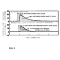
- FIG. 2 is a graph used for explaining the definition of waves.
- the horizontal axis shows time.
- the waveform of discharge current is shown on the upper side of the graph, and the intensity waveform of discharge light emission measured simultaneously is shown on the lower side of the graph.
- discharge current is evaluated on the basis of the intensity of the measured discharge light emission.
- the peak value ip of discharge current is evaluated on the basis of the peak value Lp of the light intensity waveform.
- the peak value ip of discharge current may be evaluated on the basis of the area Lq of light intensity waveform.
- the charge quantity q which is the integral value of the discharge current is evaluated on the basis of the area (integral value) Lq of the light intensity waveform.
- the charge quantity q may be evaluated on the basis of the light intensity peak Lp.
- the discharge energy E is evaluated on the basis of the area (integral value) Lq of the light intensity waveform or the light intensity peak Lp. The details of the evaluation will be described later.
- FIGS. 3(A) and 3(B) are circuit diagrams exemplifying non-contact discharge evaluation apparatuses which differ from each other.
- the circuit diagram shown in FIG. 3(B) differs from the circuit diagram shown in FIG. 3(A) only in the point that the light receiving element is connected through an optical guide and the point that a light receiving element, a current measurement apparatus, and a digital oscilloscope are disposed in an electromagnetic shield box.
- the power supply voltage may be the output voltage of an ESD gun (in the case of an electrostatic discharge test) or a lightening impulse voltage (in the case of a lightening impulse test).
- the power supply voltage may be an AC or DC test voltage.
- the applied voltage, the polarity of the applied voltage, and the instantaneous voltage and it generation time (or phase) at the time of generation of discharge are known.
- the discharge current is measured by a current measuring apparatus. However, at the time of a discharge test or maintenance/operation performed after creation of the database, discharge current is not measured, and only the measurement of the light emission intensity waveform by the light receiving element is performed.
- a database When a database is created or when discharge of a piece of equipment under measurement is evaluated, light emission is detected using the same light receiving element or a light receiving element of the same type (i.e., having the same characteristic).
- the optical signal input to each light receiving element is weakened or its sensitivity is increased.
- the sensitivity is increased or decreased in accordance with the light emission intensity by increasing or decreasing the distance between the light receiving element and the light emission source, disposing an optical filter, using an optical guide such as optical fiber, or adjusting the gain of the light receiving element.
- An example of a light receiving element having high sensitivity from the range of UV light to the range of visible light is a photomultiplier tube PMT.
- a photo diode may be used instead of the photomultiplier tube PMT.
- a light-weakening filter is used.
- the light receiving element is disposed to spatially face the discharge source so as to detect generation of discharge.
- the light receiving element may be coupled with the discharge source through an optical guide such as optical fiber.
- the positional relation between the discharge source and the light receiving element can be set such that they are not located on a common straight line, and they can be separated from each other. This configuration can suppress the influence, on the light receiving element, of electrical noise from the power supply or the discharge source.
- the light receiving element In the case where a strong noise source exists and noise is induced in a light receiving element to be used, the light receiving element is separated from a portion where discharge light is emitted, and a light emission signal is transmitted therebetween through an optical fiber cable. In this case, the light emission signal attenuates. Therefore, evaluation is performed in consideration of attenuation of the light emission intensity at the optical fiber cable.
- an optical fiber may also be used when the quantity of light is large (the light intensity drops as a result of passage through the fiber).
- Use of an optical guide such as optical fiber not only reduces electrical noise but also allows flexible determination of the positions of a portion where light emission occurs (light source) and the light receiving element.
- FIGS. 4(A) and 4(B) are graphs showing an example of a characteristic when an optical guide (optical fiber) is used.
- FIG. 4(A) shows the relation between the intensity of discharge light emission and discharge current
- FIG. 4(B) shows the relation between the integral value of discharge light emission and the charge quantity of discharge.
- the intensity Lp of discharge light emission is smaller.
- the intensity Lp of discharge light emission and the peak value ip of discharge current have a linear relationship in both the case where an optical fiber is used and the case where no optical fiber is used.
- FIG. 4(A) shows the relation between the intensity of discharge light emission and discharge current
- FIG. 4(A) shows the relation between the intensity of discharge light emission and discharge current
- the intensity Lp of discharge light emission and the peak value ip of discharge current have a linear relationship in both the case where an optical fiber is used and the case where no optical fiber is used.
- the integral value Lq of discharge light emission and the charge quantity q of discharge have a linear relationship in both the case where an optical fiber is used and the case where no optical fiber is used.
- the characteristic obtained when the optical fiber is used is normalized to the characteristic obtained when the optical fiber is not used such that the two characteristics become the same.
- the influence of electrical noise can be suppressed further.
- a light emitting portion and the light receiving element must be located on a straight line within the angular field of view of the light receiving element.
- use of an optical guide removes the restriction (the light receiving element must be located on a straight line within the angular field of view), and allows the light receiving element to be disposed freely disposed, for example, behind a shield or within an electromagnetic shield box disposed at an arbitrary position.
- a metal mesh which does not allow passage of electrical noise therethrough but allows passage of optical signals therethrough is disposed as an electromagnetic shield box covering the entire surface of the light receiving element. Also, it is desired that the current measuring apparatus be disposed in the electromagnetic shield box.
- the wiring distances between the light receiving elements and a waveform intensity obtaining apparatus such as a digital oscilloscope DOSC are made equal to one another (in the case where the distances are not equal to one another, the times at which waveforms appear are corrected in accordance with length differences thereamong).
- a waveform intensity obtaining apparatus such as a digital oscilloscope DOSC
- the generation positions and differences between the generation times can be known more specifically by performing experimental observation one time.
- the optical guide such as optical fiber must have a diameter sufficient for observation of the size of discharge light emission.
- the optical guide may be a single thick optical fiber or a bundle of a plurality of optical fibers.
- the optical guide such as optical fiber is disposed at a position at which discharge light emission can be received efficiently. Therefore, light may be condensed through use of, for example, a lens which allows passage of light over the entire range of wavelengths of emitted light.
- the light emission intensity waveform detected by the light receiving element is observed by the waveform obtaining apparatus such as a digital oscilloscope DOSC.
- data representing the light emission intensity waveform are obtained.
- the frequency band and sampling frequency of the oscilloscope must be sufficient to cope with changes in the light emission intensity waveform. For example, it is desired that the frequency band be equal to or higher than 500 MHz, and the sampling frequency be equal to or higher than 1 GS/s.
- the signal from the light receiving element itself is used as a trigger of the digital oscilloscope DOSC. However, in an electrostatic discharge test or a lightening impulse test, a single-short voltage or a single-short current is applied.
- a drive signal of a tester used in such a test for example, an ESD gun used in the electrostatic discharge test or a lightening impulse voltage or current generator used in the lightening impulse test
- its output application signal may be used as a trigger signal.
- An electromagnetic wave radiated from the drive signal or output application signal may be detected by an antenna and be used as a trigger signal.
- observation is performed within a predetermined time period or at a predetermined phase (in the case where an AC signal is used).
- a delay circuit or a pulse generator which produces a trigger signal at the predetermined time or phase.
- the light emission intensity waveform obtained by the waveform obtaining apparatus such as a digital oscilloscope DOSC is analyzed by a waveform analyzing section.
- a database for each light receiving element to be used and for the discharge environment of each insulation system of interest, the relation between the peak value Lp of the light intensity waveform or the area Lq of the light intensity waveform and the peak value ip of the discharge current value, the charge quantity q of discharge (the integral value of the discharge current waveform), or the discharge energy E is obtained from the analysis data sets in consideration of applied power information (applied voltage, polarity, instantaneous voltage and its generation time (or phase) when discharge is generated.
- the obtained relation is recorded in the database.
- the light emission data obtained by the analysis are compared with the data recorded in the database so as to estimate the magnitude of discharge (current peak value, charge quantity of discharge, and discharge energy). The results of the estimation are displayed.
- FIG. 5 is a graph showing an influence due to a difference between light receiving elements.
- FIG. 5 shows the results of an experiment in which the same discharge light emission was measured using different types of photomultiplier tubes PMT. Although the light emission intensity changes depending on the type of the element (photomultiplier tube PMT) used, the magnitude of discharge can be evaluated quantitatively by creating a database for each element to be used.
- FIG. 6 is a detailed diagram of the waveform analysis, comparison, and evaluation shown in FIGS. 3(A) and 3(B) .
- Values representing the discharge light emission intensity waveform and the discharge current waveform are led from the digital oscilloscope DOSC to an integration circuit and a peak detection circuit of the waveform analyzing section.
- the integration circuit calculates the integral value Lq of the output waveform of the light receiving element and the integral value q of the output waveform of the current conversion probe CT or the current waveform detection apparatus.
- the peak detection circuit calculates the peak value Lp of the output waveform of the light receiving element and the peak value ip of the output waveform of the current conversion probe CT or the current waveform detection apparatus.
- the discharge energy E is calculated by obtaining the product of the output q from the integration circuit and the voltage V at the time of emission of light (applied power information).
- the peak value ip of the discharge current waveform, the charge quantity q of discharge which is the area (time integral value) of the waveform, and the discharge energy E are evaluated on the basis of the peak value Lp and integral value Lq of the output waveform of the light receiving element.
- the peak value ip of the discharge current waveform is evaluated on the basis of the peak value Lp of the output waveform of the light receiving element
- the charge quantity q of discharge is evaluated on the basis of the integral value Lq of the output waveform of the light receiving element.
- the discharge energy E may be evaluated on the basis of the peak value Lp or the integral value Lq because a large difference is not produced between the two cases.
- FIG. 7 is a graph used for explaining an operation of measuring a light emission signal, such as the peak value Lp of the light emission intensity waveform or the integral value Lq of the light emission intensity, simultaneously with the peak value of discharge current and estimating the peak ip of discharge current from Lp or Lq on the characteristic curves shown in FIG. 7 .
- a light emission signal such as the peak value Lp of the light emission intensity waveform or the integral value Lq of the light emission intensity
- plots show actually measured values
- lines show approximate characteristic curves corrected for creation of a database.
- the points on the characteristic curves of this graph are recorded in the database in the form of a table.
- the relation between the peak value ip of the discharge current waveform and the peak value Lp of the output waveform is more linear than the relation between the peak value ip of the discharge current waveform and the integral value Lq.
- the peak value Lp of the output waveform be used for estimation of the peak value ip of the discharge current waveform.
- the peak value ip can be estimated using an approximate characteristic curve.
- the output peak value ip corresponding to the input value of the peak value Lp or the integral value Lq can be obtained on the basis of the above-mentioned relation in the form of a table or by formulating the approximate characteristic curve (providing the output peak value ip corresponding to the input peak value Lp or integral value Lq) and obtaining a function thereof.
- FIG. 8 is a graph used for explaining an operation of measuring a light emission signal, such as the peak value Lp of the light emission intensity waveform or the integral value Lq of the light emission intensity, simultaneously with the charge quantity of discharge and estimating the charge quantity q of discharge from the peak value Lp or the integral value Lq on the characteristic curves shown in FIG. 8 .
- a light emission signal such as the peak value Lp of the light emission intensity waveform or the integral value Lq of the light emission intensity
- plots show actually measured values
- lines show approximate characteristic curves corrected for creation of a database.
- the points on the characteristic curves of this graph are recorded in the database in the form of a table.
- the relation between the charge quantity q of discharge and the integral value Lq is more linear than the relation between the charge quantity q of discharge and the peak value Lp.
- the integral value Lq be used for estimation of the charge quantity q of discharge.
- the charge quantity q of discharge can be estimated using an approximate characteristic curve.
- the output charge quantity q corresponding to the input value of the integral value Lq or the peak value Lp can be obtained on the basis of the above-mentioned relation in the form of a table or by formulating the approximate characteristic curve (providing the output charge quantity q corresponding to the input integral value Lq or peak value Lp) and obtaining a function thereof.
- FIG. 9 is a graph used for explaining an operation of measuring a light emission signal, such as the peak value Lp of the light emission intensity waveform or the integral value Lq of the light emission intensity, simultaneously with discharge energy and estimating the discharge energy E from the characteristic curves shown in FIG. 9 .
- a light emission signal such as the peak value Lp of the light emission intensity waveform or the integral value Lq of the light emission intensity
- plots show actually measured values, and lines show approximate characteristic curves corrected for creation of a database.
- the points on the characteristic curves of this graph are recorded in the database in the form of a table.
- the relation between the discharge energy E and the integral value Lq is more linear than the relation between the discharge energy E and the peak value Lp.
- the integral value Lq be used for estimation of the discharge energy E.
- the discharge energy E can be estimated using an approximate characteristic curve.
- the output discharge energy E corresponding to the input value of the peak value Lp or the integral value Lq can be obtained on the basis of the above-mentioned relation in the form of a table or by formulating the approximate characteristic curve (providing the output discharge energy E corresponding to the input peak value Lp or integral value Lq) and obtaining a function thereof.
- FIG. 10 is a graph used for explaining differences produced between different types of insulating gases which are examples of different insulation systems.
- FIG. 10 is a graph showing the relation between the peak value Lp of discharge light emission and the peak value ip of discharge current ip for each of different types of insulating gases. Since the above-described evaluation changes depending on the discharge environment (gas insulation or liquid insulation used), it is necessary to obtain data for each type of insulation gas of interest in advance. Notably, in the present embodiment, the relation between the peak value Lp of discharge light emission and the peak value ip of discharge current ip is shown.
- FIG. 10 shows an example in which the characteristic change depending on the type of the insulation medium (insulation gas in the present example). In the case where the form of discharge changes greatly, data are prepared for each of different discharge forms, which allows more specific evaluation of discharge quantity.
- the intensity of an optical signal changes depending on the distance d between the position of light emission and the sensor position (the greater the distance d, the greater the degree to which the intensity of the optical signal drops). Therefore, correction is performed in consideration of this dependency on the distance d. Namely, since the light emission intensity is inverse proportional to the square of the distance d, correction for increasing and decreasing the light emission intensity is performed on the basis of this relation and in consideration of the distance d between the position of light emission and the sensor position.
- the discharge generation portion In the case of a discharge test, the discharge generation portion is an electrode and is known. In contrast, in the case of maintenance diagnosis, since the discharge generation portion is unknown, a position locating technique becomes necessary. In the position locating, since the light emission signal attenuates in inverse proportional to the square of the distance between the generation position and the light receiving element, the data (produced under the assumption that the distance between a generation source and the light receiving element is a predetermined distance) recorded in the database must be subjected to distance correction.
- a relative change in the magnitude of discharge can be evaluated through use of the relation between two values having a linear relation therebetween, such as the relation between the peak value Lp of discharge light emission and the peak value ip of discharge current or the relation between the integral value Lq of discharge light emission and the charge quantity q of discharge.
Landscapes
- Physics & Mathematics (AREA)
- General Physics & Mathematics (AREA)
- Health & Medical Sciences (AREA)
- Nuclear Medicine, Radiotherapy & Molecular Imaging (AREA)
- Life Sciences & Earth Sciences (AREA)
- Chemical & Material Sciences (AREA)
- Analytical Chemistry (AREA)
- Biochemistry (AREA)
- General Health & Medical Sciences (AREA)
- Immunology (AREA)
- Pathology (AREA)
- Testing Relating To Insulation (AREA)
- Testing Electric Properties And Detecting Electric Faults (AREA)
- Investigating, Analyzing Materials By Fluorescence Or Luminescence (AREA)
Applications Claiming Priority (2)
| Application Number | Priority Date | Filing Date | Title |
|---|---|---|---|
| JP2012013305A JP5854468B2 (ja) | 2012-01-25 | 2012-01-25 | 非接触放電評価方法及び装置 |
| PCT/JP2012/080816 WO2013111445A1 (ja) | 2012-01-25 | 2012-11-29 | 非接触放電評価方法及び装置 |
Publications (3)
| Publication Number | Publication Date |
|---|---|
| EP2808673A1 true EP2808673A1 (de) | 2014-12-03 |
| EP2808673A4 EP2808673A4 (de) | 2015-11-04 |
| EP2808673B1 EP2808673B1 (de) | 2019-10-30 |
Family
ID=48873186
Family Applications (1)
| Application Number | Title | Priority Date | Filing Date |
|---|---|---|---|
| EP12866479.4A Not-in-force EP2808673B1 (de) | 2012-01-25 | 2012-11-29 | Kontaktloses entladungsbeurteilungsverfahren und kontaktlose entladungsbeurteilungsvorrichtung |
Country Status (4)
| Country | Link |
|---|---|
| US (1) | US9442154B2 (de) |
| EP (1) | EP2808673B1 (de) |
| JP (1) | JP5854468B2 (de) |
| WO (1) | WO2013111445A1 (de) |
Families Citing this family (9)
| Publication number | Priority date | Publication date | Assignee | Title |
|---|---|---|---|---|
| JP6345803B2 (ja) * | 2015-07-31 | 2018-06-20 | 株式会社日立製作所 | 部分放電検出装置及び部分放電検出方法 |
| CN105372562B (zh) * | 2015-10-21 | 2017-07-14 | 国网新疆电力公司检修公司 | 一种利用设定指标检测紫外放电程度的方法及系统 |
| KR102449873B1 (ko) * | 2015-12-11 | 2022-10-04 | 삼성전자주식회사 | 플래시를 포함하는 촬상 장치를 제어하는 방법 및 촬상장치 |
| DE102018217335A1 (de) * | 2018-10-10 | 2020-04-16 | Robert Bosch Gmbh | Verfahren zum Betreiben eines Verbrennungsmotors, Steuergerät zur Durchführung des Verfahrens |
| JP7149049B2 (ja) | 2018-11-07 | 2022-10-06 | 株式会社Subaru | 放電探知システム及び放電探知方法 |
| JP7541807B2 (ja) | 2020-03-09 | 2024-08-29 | 株式会社Subaru | 引火性スパーク評価システム及び引火性スパーク評価方法 |
| DE102020119012B4 (de) * | 2020-07-17 | 2022-05-19 | Hochschule Für Technik Und Wirtschaft Berlin | Vorrichtung und Verfahren zum Bestimmen einer Ladungsstärke einer Teilentladung |
| CN111983361B (zh) * | 2020-08-24 | 2023-03-21 | Oppo(重庆)智能科技有限公司 | 测试治具及控制方法、电子设备及控制方法和测试系统 |
| CN113361091B (zh) * | 2021-06-01 | 2022-05-17 | 杭州电力设备制造有限公司 | 一种esd强度估计方法和系统 |
Family Cites Families (10)
| Publication number | Priority date | Publication date | Assignee | Title |
|---|---|---|---|---|
| JP2707823B2 (ja) | 1989-10-13 | 1998-02-04 | 富士電機株式会社 | 電気機器の故障監視装置 |
| US6476396B1 (en) * | 1999-04-09 | 2002-11-05 | Keith W. Forsyth | Electro-optical, non-contact measurement of electrical discharges |
| JP2008268083A (ja) * | 2007-04-23 | 2008-11-06 | Toyota Motor Corp | 絶縁検査装置および絶縁検査方法 |
| JP2008304357A (ja) * | 2007-06-08 | 2008-12-18 | Mitsubishi Electric Corp | 部分放電計測装置 |
| US20090015814A1 (en) * | 2007-07-11 | 2009-01-15 | Carl Zeiss Smt Ag | Detector for registering a light intensity, and illumination system equipped with the detector |
| JP5305384B2 (ja) * | 2008-10-22 | 2013-10-02 | 国立大学法人九州工業大学 | 部分放電発光検出方法及び装置 |
| KR101028884B1 (ko) * | 2008-12-30 | 2011-04-12 | 한국전기안전공사 | 유브이 센서어레이를 이용한 부분 방전량 측정 장치 및 방법 |
| JP2010204067A (ja) | 2009-03-06 | 2010-09-16 | Ehime Univ | 部分放電発生回数測定装置 |
| JP2011099775A (ja) * | 2009-11-06 | 2011-05-19 | Toshiba Industrial Products Manufacturing Corp | 部分放電電流計測システム |
| US20120280717A1 (en) * | 2009-12-11 | 2012-11-08 | Junhua Fu | Method For Arc Detection And Devices Thereof |
-
2012
- 2012-01-25 JP JP2012013305A patent/JP5854468B2/ja not_active Expired - Fee Related
- 2012-11-29 US US14/374,424 patent/US9442154B2/en not_active Expired - Fee Related
- 2012-11-29 WO PCT/JP2012/080816 patent/WO2013111445A1/ja not_active Ceased
- 2012-11-29 EP EP12866479.4A patent/EP2808673B1/de not_active Not-in-force
Also Published As
| Publication number | Publication date |
|---|---|
| WO2013111445A1 (ja) | 2013-08-01 |
| EP2808673A4 (de) | 2015-11-04 |
| US9442154B2 (en) | 2016-09-13 |
| EP2808673B1 (de) | 2019-10-30 |
| JP2013152155A (ja) | 2013-08-08 |
| JP5854468B2 (ja) | 2016-02-09 |
| US20140361789A1 (en) | 2014-12-11 |
Similar Documents
| Publication | Publication Date | Title |
|---|---|---|
| US9442154B2 (en) | Non-contact discharge evaluation method and non-contact discharge evaluation apparatus | |
| JP6103353B2 (ja) | 非接触放電試験方法及び装置 | |
| US10012688B2 (en) | Discharge occurrence status evaluation device and evaluation method | |
| Schwarz et al. | Modern technologies in optical partial discharge detection | |
| US20130179100A1 (en) | System for analyzing and locating partial discharges | |
| JP2010085366A (ja) | 高電圧電気機器の絶縁異常診断装置 | |
| JP2010518412A (ja) | 静電気放電現象を検出するシステム、方法、及びコンピュータプログラム | |
| EP0767918B1 (de) | Abschirmungsintegritätsüberwachung | |
| JP2011215067A (ja) | 絶縁診断方法、絶縁診断システムおよび回転電機 | |
| JP6231110B2 (ja) | 部分放電計測法およびそれを用いて検査した高電圧機器 | |
| JP5204558B2 (ja) | インパルス試験用放電計測装置及び放電判別方法 | |
| Sakoda et al. | Diagnostics of insulation deterioration of ethylene propylene rubber using an acoustic emission technique | |
| Naderiallaf et al. | Modeling air pressure impact on PDIV for rectangular wire turn-to-turn insulation of inverter-fed motors under different voltage waveform excitations | |
| Gupta et al. | Sensitivity analysis of corona discharges measuring instruments using different electrodes and high voltage supplies | |
| CN223078455U (zh) | 用于射线发生模块的检测装置和射线发生设备 | |
| Kumari | Feasibility study for usage of optical partial discharge detection in HV cable termination | |
| Seltzer-grant et al. | On-Line PD Spot Testing and Continuous Monitoring for In Service Power Cables–Techniques and Field Experiences | |
| Habel et al. | Fibre-optic Sensors for Early Damage Detection in Plastic Insulations of High Voltage Facilities | |
| Gortschakow et al. | Electro-Optical Diagnostics of Single Partial Discharges | |
| Palitó et al. | Acoustic detection of single and multiple air-gap partial discharges with piezoelectrets transducers | |
| Nugraha et al. | Investigation of DC corona discharge properties using UHF method | |
| Vigni et al. | Enhancing Partial Discharge Sensitivity Over Distance by Active Capacitive Sensors | |
| Kang et al. | Optical Detection of Corona Discharge Based on SiPM at DC Voltage | |
| Seltzer-Grant et al. | New techniques for on-line partial discharge testing of solid-insulated outdoor mv and hv plant | |
| Georghiou et al. | Guarding your assets. Online monitoring tackles partial discharges |
Legal Events
| Date | Code | Title | Description |
|---|---|---|---|
| PUAI | Public reference made under article 153(3) epc to a published international application that has entered the european phase |
Free format text: ORIGINAL CODE: 0009012 |
|
| 17P | Request for examination filed |
Effective date: 20140825 |
|
| AK | Designated contracting states |
Kind code of ref document: A1 Designated state(s): AL AT BE BG CH CY CZ DE DK EE ES FI FR GB GR HR HU IE IS IT LI LT LU LV MC MK MT NL NO PL PT RO RS SE SI SK SM TR |
|
| DAX | Request for extension of the european patent (deleted) | ||
| RA4 | Supplementary search report drawn up and despatched (corrected) |
Effective date: 20151007 |
|
| RIC1 | Information provided on ipc code assigned before grant |
Ipc: G01N 21/67 20060101AFI20151001BHEP Ipc: H01T 15/00 20060101ALI20151001BHEP Ipc: G01R 31/12 20060101ALI20151001BHEP Ipc: H01T 13/60 20110101ALI20151001BHEP Ipc: G01R 31/00 20060101ALI20151001BHEP |
|
| GRAP | Despatch of communication of intention to grant a patent |
Free format text: ORIGINAL CODE: EPIDOSNIGR1 |
|
| STAA | Information on the status of an ep patent application or granted ep patent |
Free format text: STATUS: GRANT OF PATENT IS INTENDED |
|
| INTG | Intention to grant announced |
Effective date: 20190628 |
|
| GRAS | Grant fee paid |
Free format text: ORIGINAL CODE: EPIDOSNIGR3 |
|
| GRAA | (expected) grant |
Free format text: ORIGINAL CODE: 0009210 |
|
| STAA | Information on the status of an ep patent application or granted ep patent |
Free format text: STATUS: THE PATENT HAS BEEN GRANTED |
|
| AK | Designated contracting states |
Kind code of ref document: B1 Designated state(s): AL AT BE BG CH CY CZ DE DK EE ES FI FR GB GR HR HU IE IS IT LI LT LU LV MC MK MT NL NO PL PT RO RS SE SI SK SM TR |
|
| REG | Reference to a national code |
Ref country code: GB Ref legal event code: FG4D |
|
| REG | Reference to a national code |
Ref country code: CH Ref legal event code: EP |
|
| REG | Reference to a national code |
Ref country code: AT Ref legal event code: REF Ref document number: 1196696 Country of ref document: AT Kind code of ref document: T Effective date: 20191115 |
|
| REG | Reference to a national code |
Ref country code: DE Ref legal event code: R096 Ref document number: 602012065341 Country of ref document: DE |
|
| REG | Reference to a national code |
Ref country code: IE Ref legal event code: FG4D |
|
| REG | Reference to a national code |
Ref country code: LT Ref legal event code: MG4D |
|
| PG25 | Lapsed in a contracting state [announced via postgrant information from national office to epo] |
Ref country code: PT Free format text: LAPSE BECAUSE OF FAILURE TO SUBMIT A TRANSLATION OF THE DESCRIPTION OR TO PAY THE FEE WITHIN THE PRESCRIBED TIME-LIMIT Effective date: 20200302 Ref country code: ES Free format text: LAPSE BECAUSE OF FAILURE TO SUBMIT A TRANSLATION OF THE DESCRIPTION OR TO PAY THE FEE WITHIN THE PRESCRIBED TIME-LIMIT Effective date: 20191030 Ref country code: GR Free format text: LAPSE BECAUSE OF FAILURE TO SUBMIT A TRANSLATION OF THE DESCRIPTION OR TO PAY THE FEE WITHIN THE PRESCRIBED TIME-LIMIT Effective date: 20200131 Ref country code: PL Free format text: LAPSE BECAUSE OF FAILURE TO SUBMIT A TRANSLATION OF THE DESCRIPTION OR TO PAY THE FEE WITHIN THE PRESCRIBED TIME-LIMIT Effective date: 20191030 Ref country code: LT Free format text: LAPSE BECAUSE OF FAILURE TO SUBMIT A TRANSLATION OF THE DESCRIPTION OR TO PAY THE FEE WITHIN THE PRESCRIBED TIME-LIMIT Effective date: 20191030 Ref country code: NO Free format text: LAPSE BECAUSE OF FAILURE TO SUBMIT A TRANSLATION OF THE DESCRIPTION OR TO PAY THE FEE WITHIN THE PRESCRIBED TIME-LIMIT Effective date: 20200130 Ref country code: NL Free format text: LAPSE BECAUSE OF FAILURE TO SUBMIT A TRANSLATION OF THE DESCRIPTION OR TO PAY THE FEE WITHIN THE PRESCRIBED TIME-LIMIT Effective date: 20191030 Ref country code: LV Free format text: LAPSE BECAUSE OF FAILURE TO SUBMIT A TRANSLATION OF THE DESCRIPTION OR TO PAY THE FEE WITHIN THE PRESCRIBED TIME-LIMIT Effective date: 20191030 Ref country code: SE Free format text: LAPSE BECAUSE OF FAILURE TO SUBMIT A TRANSLATION OF THE DESCRIPTION OR TO PAY THE FEE WITHIN THE PRESCRIBED TIME-LIMIT Effective date: 20191030 Ref country code: FI Free format text: LAPSE BECAUSE OF FAILURE TO SUBMIT A TRANSLATION OF THE DESCRIPTION OR TO PAY THE FEE WITHIN THE PRESCRIBED TIME-LIMIT Effective date: 20191030 Ref country code: BG Free format text: LAPSE BECAUSE OF FAILURE TO SUBMIT A TRANSLATION OF THE DESCRIPTION OR TO PAY THE FEE WITHIN THE PRESCRIBED TIME-LIMIT Effective date: 20200130 |
|
| PGFP | Annual fee paid to national office [announced via postgrant information from national office to epo] |
Ref country code: GB Payment date: 20191220 Year of fee payment: 8 |
|
| REG | Reference to a national code |
Ref country code: NL Ref legal event code: MP Effective date: 20191030 |
|
| PG25 | Lapsed in a contracting state [announced via postgrant information from national office to epo] |
Ref country code: RS Free format text: LAPSE BECAUSE OF FAILURE TO SUBMIT A TRANSLATION OF THE DESCRIPTION OR TO PAY THE FEE WITHIN THE PRESCRIBED TIME-LIMIT Effective date: 20191030 Ref country code: IS Free format text: LAPSE BECAUSE OF FAILURE TO SUBMIT A TRANSLATION OF THE DESCRIPTION OR TO PAY THE FEE WITHIN THE PRESCRIBED TIME-LIMIT Effective date: 20200229 Ref country code: HR Free format text: LAPSE BECAUSE OF FAILURE TO SUBMIT A TRANSLATION OF THE DESCRIPTION OR TO PAY THE FEE WITHIN THE PRESCRIBED TIME-LIMIT Effective date: 20191030 |
|
| REG | Reference to a national code |
Ref country code: DE Ref legal event code: R119 Ref document number: 602012065341 Country of ref document: DE |
|
| PG25 | Lapsed in a contracting state [announced via postgrant information from national office to epo] |
Ref country code: AL Free format text: LAPSE BECAUSE OF FAILURE TO SUBMIT A TRANSLATION OF THE DESCRIPTION OR TO PAY THE FEE WITHIN THE PRESCRIBED TIME-LIMIT Effective date: 20191030 |
|
| REG | Reference to a national code |
Ref country code: CH Ref legal event code: PL |
|
| PG25 | Lapsed in a contracting state [announced via postgrant information from national office to epo] |
Ref country code: EE Free format text: LAPSE BECAUSE OF FAILURE TO SUBMIT A TRANSLATION OF THE DESCRIPTION OR TO PAY THE FEE WITHIN THE PRESCRIBED TIME-LIMIT Effective date: 20191030 Ref country code: LU Free format text: LAPSE BECAUSE OF NON-PAYMENT OF DUE FEES Effective date: 20191129 Ref country code: DK Free format text: LAPSE BECAUSE OF FAILURE TO SUBMIT A TRANSLATION OF THE DESCRIPTION OR TO PAY THE FEE WITHIN THE PRESCRIBED TIME-LIMIT Effective date: 20191030 Ref country code: CH Free format text: LAPSE BECAUSE OF NON-PAYMENT OF DUE FEES Effective date: 20191130 Ref country code: MC Free format text: LAPSE BECAUSE OF FAILURE TO SUBMIT A TRANSLATION OF THE DESCRIPTION OR TO PAY THE FEE WITHIN THE PRESCRIBED TIME-LIMIT Effective date: 20191030 Ref country code: LI Free format text: LAPSE BECAUSE OF NON-PAYMENT OF DUE FEES Effective date: 20191130 Ref country code: RO Free format text: LAPSE BECAUSE OF FAILURE TO SUBMIT A TRANSLATION OF THE DESCRIPTION OR TO PAY THE FEE WITHIN THE PRESCRIBED TIME-LIMIT Effective date: 20191030 Ref country code: CZ Free format text: LAPSE BECAUSE OF FAILURE TO SUBMIT A TRANSLATION OF THE DESCRIPTION OR TO PAY THE FEE WITHIN THE PRESCRIBED TIME-LIMIT Effective date: 20191030 |
|
| REG | Reference to a national code |
Ref country code: AT Ref legal event code: MK05 Ref document number: 1196696 Country of ref document: AT Kind code of ref document: T Effective date: 20191030 |
|
| REG | Reference to a national code |
Ref country code: BE Ref legal event code: MM Effective date: 20191130 |
|
| PG25 | Lapsed in a contracting state [announced via postgrant information from national office to epo] |
Ref country code: SM Free format text: LAPSE BECAUSE OF FAILURE TO SUBMIT A TRANSLATION OF THE DESCRIPTION OR TO PAY THE FEE WITHIN THE PRESCRIBED TIME-LIMIT Effective date: 20191030 Ref country code: SK Free format text: LAPSE BECAUSE OF FAILURE TO SUBMIT A TRANSLATION OF THE DESCRIPTION OR TO PAY THE FEE WITHIN THE PRESCRIBED TIME-LIMIT Effective date: 20191030 Ref country code: IT Free format text: LAPSE BECAUSE OF FAILURE TO SUBMIT A TRANSLATION OF THE DESCRIPTION OR TO PAY THE FEE WITHIN THE PRESCRIBED TIME-LIMIT Effective date: 20191030 |
|
| PLBE | No opposition filed within time limit |
Free format text: ORIGINAL CODE: 0009261 |
|
| STAA | Information on the status of an ep patent application or granted ep patent |
Free format text: STATUS: NO OPPOSITION FILED WITHIN TIME LIMIT |
|
| 26N | No opposition filed |
Effective date: 20200731 |
|
| PG25 | Lapsed in a contracting state [announced via postgrant information from national office to epo] |
Ref country code: DE Free format text: LAPSE BECAUSE OF NON-PAYMENT OF DUE FEES Effective date: 20200603 Ref country code: FR Free format text: LAPSE BECAUSE OF NON-PAYMENT OF DUE FEES Effective date: 20191230 Ref country code: IE Free format text: LAPSE BECAUSE OF NON-PAYMENT OF DUE FEES Effective date: 20191129 |
|
| PG25 | Lapsed in a contracting state [announced via postgrant information from national office to epo] |
Ref country code: BE Free format text: LAPSE BECAUSE OF NON-PAYMENT OF DUE FEES Effective date: 20191130 Ref country code: SI Free format text: LAPSE BECAUSE OF FAILURE TO SUBMIT A TRANSLATION OF THE DESCRIPTION OR TO PAY THE FEE WITHIN THE PRESCRIBED TIME-LIMIT Effective date: 20191030 Ref country code: AT Free format text: LAPSE BECAUSE OF FAILURE TO SUBMIT A TRANSLATION OF THE DESCRIPTION OR TO PAY THE FEE WITHIN THE PRESCRIBED TIME-LIMIT Effective date: 20191030 |
|
| PG25 | Lapsed in a contracting state [announced via postgrant information from national office to epo] |
Ref country code: CY Free format text: LAPSE BECAUSE OF FAILURE TO SUBMIT A TRANSLATION OF THE DESCRIPTION OR TO PAY THE FEE WITHIN THE PRESCRIBED TIME-LIMIT Effective date: 20191030 |
|
| GBPC | Gb: european patent ceased through non-payment of renewal fee |
Effective date: 20201129 |
|
| PG25 | Lapsed in a contracting state [announced via postgrant information from national office to epo] |
Ref country code: MT Free format text: LAPSE BECAUSE OF FAILURE TO SUBMIT A TRANSLATION OF THE DESCRIPTION OR TO PAY THE FEE WITHIN THE PRESCRIBED TIME-LIMIT Effective date: 20191030 Ref country code: HU Free format text: LAPSE BECAUSE OF FAILURE TO SUBMIT A TRANSLATION OF THE DESCRIPTION OR TO PAY THE FEE WITHIN THE PRESCRIBED TIME-LIMIT; INVALID AB INITIO Effective date: 20121129 |
|
| PG25 | Lapsed in a contracting state [announced via postgrant information from national office to epo] |
Ref country code: GB Free format text: LAPSE BECAUSE OF NON-PAYMENT OF DUE FEES Effective date: 20201129 |
|
| PG25 | Lapsed in a contracting state [announced via postgrant information from national office to epo] |
Ref country code: TR Free format text: LAPSE BECAUSE OF FAILURE TO SUBMIT A TRANSLATION OF THE DESCRIPTION OR TO PAY THE FEE WITHIN THE PRESCRIBED TIME-LIMIT Effective date: 20191030 |
|
| PG25 | Lapsed in a contracting state [announced via postgrant information from national office to epo] |
Ref country code: MK Free format text: LAPSE BECAUSE OF FAILURE TO SUBMIT A TRANSLATION OF THE DESCRIPTION OR TO PAY THE FEE WITHIN THE PRESCRIBED TIME-LIMIT Effective date: 20191030 |