EP2808528B1 - Fluid expansion motor - Google Patents
Fluid expansion motor Download PDFInfo
- Publication number
- EP2808528B1 EP2808528B1 EP13169300.4A EP13169300A EP2808528B1 EP 2808528 B1 EP2808528 B1 EP 2808528B1 EP 13169300 A EP13169300 A EP 13169300A EP 2808528 B1 EP2808528 B1 EP 2808528B1
- Authority
- EP
- European Patent Office
- Prior art keywords
- fluid
- piston
- actuator module
- central shaft
- temperature chamber
- Prior art date
- Legal status (The legal status is an assumption and is not a legal conclusion. Google has not performed a legal analysis and makes no representation as to the accuracy of the status listed.)
- Active
Links
- 239000012530 fluid Substances 0.000 title claims description 70
- 238000006073 displacement reaction Methods 0.000 claims description 26
- 238000001816 cooling Methods 0.000 claims description 23
- 239000007789 gas Substances 0.000 claims description 10
- 230000005855 radiation Effects 0.000 claims description 8
- 239000001307 helium Substances 0.000 claims description 3
- 229910052734 helium Inorganic materials 0.000 claims description 3
- SWQJXJOGLNCZEY-UHFFFAOYSA-N helium atom Chemical compound [He] SWQJXJOGLNCZEY-UHFFFAOYSA-N 0.000 claims description 3
- 239000001257 hydrogen Substances 0.000 claims description 3
- 229910052739 hydrogen Inorganic materials 0.000 claims description 3
- 125000004435 hydrogen atom Chemical class [H]* 0.000 claims description 3
- 230000005540 biological transmission Effects 0.000 claims 1
- 238000010438 heat treatment Methods 0.000 description 20
- 238000002485 combustion reaction Methods 0.000 description 5
- 230000007423 decrease Effects 0.000 description 4
- 239000000567 combustion gas Substances 0.000 description 2
- 230000000694 effects Effects 0.000 description 2
- 239000000446 fuel Substances 0.000 description 2
- 238000012423 maintenance Methods 0.000 description 2
- 238000009423 ventilation Methods 0.000 description 2
- RYGMFSIKBFXOCR-UHFFFAOYSA-N Copper Chemical compound [Cu] RYGMFSIKBFXOCR-UHFFFAOYSA-N 0.000 description 1
- 238000004891 communication Methods 0.000 description 1
- 230000006835 compression Effects 0.000 description 1
- 238000007906 compression Methods 0.000 description 1
- 239000012141 concentrate Substances 0.000 description 1
- 229910052802 copper Inorganic materials 0.000 description 1
- 239000010949 copper Substances 0.000 description 1
- 238000009434 installation Methods 0.000 description 1
- 239000007788 liquid Substances 0.000 description 1
- 238000005461 lubrication Methods 0.000 description 1
- 239000000463 material Substances 0.000 description 1
- 230000010363 phase shift Effects 0.000 description 1
- 238000005086 pumping Methods 0.000 description 1
- 238000011084 recovery Methods 0.000 description 1
Images


Classifications
-
- F—MECHANICAL ENGINEERING; LIGHTING; HEATING; WEAPONS; BLASTING
- F01—MACHINES OR ENGINES IN GENERAL; ENGINE PLANTS IN GENERAL; STEAM ENGINES
- F01C—ROTARY-PISTON OR OSCILLATING-PISTON MACHINES OR ENGINES
- F01C17/00—Arrangements for drive of co-operating members, e.g. for rotary piston and casing
- F01C17/04—Arrangements for drive of co-operating members, e.g. for rotary piston and casing of cam-and-follower type
-
- F—MECHANICAL ENGINEERING; LIGHTING; HEATING; WEAPONS; BLASTING
- F02—COMBUSTION ENGINES; HOT-GAS OR COMBUSTION-PRODUCT ENGINE PLANTS
- F02G—HOT GAS OR COMBUSTION-PRODUCT POSITIVE-DISPLACEMENT ENGINE PLANTS; USE OF WASTE HEAT OF COMBUSTION ENGINES; NOT OTHERWISE PROVIDED FOR
- F02G1/00—Hot gas positive-displacement engine plants
- F02G1/04—Hot gas positive-displacement engine plants of closed-cycle type
- F02G1/043—Hot gas positive-displacement engine plants of closed-cycle type the engine being operated by expansion and contraction of a mass of working gas which is heated and cooled in one of a plurality of constantly communicating expansible chambers, e.g. Stirling cycle type engines
- F02G1/044—Hot gas positive-displacement engine plants of closed-cycle type the engine being operated by expansion and contraction of a mass of working gas which is heated and cooled in one of a plurality of constantly communicating expansible chambers, e.g. Stirling cycle type engines having at least two working members, e.g. pistons, delivering power output
-
- F—MECHANICAL ENGINEERING; LIGHTING; HEATING; WEAPONS; BLASTING
- F01—MACHINES OR ENGINES IN GENERAL; ENGINE PLANTS IN GENERAL; STEAM ENGINES
- F01B—MACHINES OR ENGINES, IN GENERAL OR OF POSITIVE-DISPLACEMENT TYPE, e.g. STEAM ENGINES
- F01B1/00—Reciprocating-piston machines or engines characterised by number or relative disposition of cylinders or by being built-up from separate cylinder-crankcase elements
- F01B1/06—Reciprocating-piston machines or engines characterised by number or relative disposition of cylinders or by being built-up from separate cylinder-crankcase elements with cylinders in star or fan arrangement
- F01B1/0603—Reciprocating-piston machines or engines characterised by number or relative disposition of cylinders or by being built-up from separate cylinder-crankcase elements with cylinders in star or fan arrangement the connection of the pistons with an element being at the outer ends of the cylinders
- F01B1/061—Reciprocating-piston machines or engines characterised by number or relative disposition of cylinders or by being built-up from separate cylinder-crankcase elements with cylinders in star or fan arrangement the connection of the pistons with an element being at the outer ends of the cylinders with two or more series radial piston-cylinder units
-
- F—MECHANICAL ENGINEERING; LIGHTING; HEATING; WEAPONS; BLASTING
- F01—MACHINES OR ENGINES IN GENERAL; ENGINE PLANTS IN GENERAL; STEAM ENGINES
- F01B—MACHINES OR ENGINES, IN GENERAL OR OF POSITIVE-DISPLACEMENT TYPE, e.g. STEAM ENGINES
- F01B1/00—Reciprocating-piston machines or engines characterised by number or relative disposition of cylinders or by being built-up from separate cylinder-crankcase elements
- F01B1/06—Reciprocating-piston machines or engines characterised by number or relative disposition of cylinders or by being built-up from separate cylinder-crankcase elements with cylinders in star or fan arrangement
- F01B1/062—Reciprocating-piston machines or engines characterised by number or relative disposition of cylinders or by being built-up from separate cylinder-crankcase elements with cylinders in star or fan arrangement the connection of the pistons with an actuating or actuated element being at the inner ends of the cylinders
-
- F—MECHANICAL ENGINEERING; LIGHTING; HEATING; WEAPONS; BLASTING
- F01—MACHINES OR ENGINES IN GENERAL; ENGINE PLANTS IN GENERAL; STEAM ENGINES
- F01B—MACHINES OR ENGINES, IN GENERAL OR OF POSITIVE-DISPLACEMENT TYPE, e.g. STEAM ENGINES
- F01B13/00—Reciprocating-piston machines or engines with rotating cylinders in order to obtain the reciprocating-piston motion
- F01B13/04—Reciprocating-piston machines or engines with rotating cylinders in order to obtain the reciprocating-piston motion with more than one cylinder
- F01B13/06—Reciprocating-piston machines or engines with rotating cylinders in order to obtain the reciprocating-piston motion with more than one cylinder in star arrangement
- F01B13/068—Reciprocating-piston machines or engines with rotating cylinders in order to obtain the reciprocating-piston motion with more than one cylinder in star arrangement the connection of the pistons with an actuated or actuating element being at the inner ends of the cylinders
-
- F—MECHANICAL ENGINEERING; LIGHTING; HEATING; WEAPONS; BLASTING
- F02—COMBUSTION ENGINES; HOT-GAS OR COMBUSTION-PRODUCT ENGINE PLANTS
- F02G—HOT GAS OR COMBUSTION-PRODUCT POSITIVE-DISPLACEMENT ENGINE PLANTS; USE OF WASTE HEAT OF COMBUSTION ENGINES; NOT OTHERWISE PROVIDED FOR
- F02G1/00—Hot gas positive-displacement engine plants
- F02G1/04—Hot gas positive-displacement engine plants of closed-cycle type
- F02G1/043—Hot gas positive-displacement engine plants of closed-cycle type the engine being operated by expansion and contraction of a mass of working gas which is heated and cooled in one of a plurality of constantly communicating expansible chambers, e.g. Stirling cycle type engines
- F02G1/053—Component parts or details
- F02G1/055—Heaters or coolers
-
- F—MECHANICAL ENGINEERING; LIGHTING; HEATING; WEAPONS; BLASTING
- F03—MACHINES OR ENGINES FOR LIQUIDS; WIND, SPRING, OR WEIGHT MOTORS; PRODUCING MECHANICAL POWER OR A REACTIVE PROPULSIVE THRUST, NOT OTHERWISE PROVIDED FOR
- F03G—SPRING, WEIGHT, INERTIA OR LIKE MOTORS; MECHANICAL-POWER PRODUCING DEVICES OR MECHANISMS, NOT OTHERWISE PROVIDED FOR OR USING ENERGY SOURCES NOT OTHERWISE PROVIDED FOR
- F03G6/00—Devices for producing mechanical power from solar energy
- F03G6/02—Devices for producing mechanical power from solar energy using a single state working fluid
- F03G6/04—Devices for producing mechanical power from solar energy using a single state working fluid gaseous
-
- F—MECHANICAL ENGINEERING; LIGHTING; HEATING; WEAPONS; BLASTING
- F03—MACHINES OR ENGINES FOR LIQUIDS; WIND, SPRING, OR WEIGHT MOTORS; PRODUCING MECHANICAL POWER OR A REACTIVE PROPULSIVE THRUST, NOT OTHERWISE PROVIDED FOR
- F03G—SPRING, WEIGHT, INERTIA OR LIKE MOTORS; MECHANICAL-POWER PRODUCING DEVICES OR MECHANISMS, NOT OTHERWISE PROVIDED FOR OR USING ENERGY SOURCES NOT OTHERWISE PROVIDED FOR
- F03G6/00—Devices for producing mechanical power from solar energy
- F03G6/06—Devices for producing mechanical power from solar energy with solar energy concentrating means
- F03G6/068—Devices for producing mechanical power from solar energy with solar energy concentrating means having other power cycles, e.g. Stirling or transcritical, supercritical cycles; combined with other power sources, e.g. wind, gas or nuclear
-
- F—MECHANICAL ENGINEERING; LIGHTING; HEATING; WEAPONS; BLASTING
- F01—MACHINES OR ENGINES IN GENERAL; ENGINE PLANTS IN GENERAL; STEAM ENGINES
- F01B—MACHINES OR ENGINES, IN GENERAL OR OF POSITIVE-DISPLACEMENT TYPE, e.g. STEAM ENGINES
- F01B9/00—Reciprocating-piston machines or engines characterised by connections between pistons and main shafts and not specific to preceding groups
- F01B9/04—Reciprocating-piston machines or engines characterised by connections between pistons and main shafts and not specific to preceding groups with rotary main shaft other than crankshaft
- F01B9/06—Reciprocating-piston machines or engines characterised by connections between pistons and main shafts and not specific to preceding groups with rotary main shaft other than crankshaft the piston motion being transmitted by curved surfaces
- F01B2009/061—Reciprocating-piston machines or engines characterised by connections between pistons and main shafts and not specific to preceding groups with rotary main shaft other than crankshaft the piston motion being transmitted by curved surfaces by cams
-
- F—MECHANICAL ENGINEERING; LIGHTING; HEATING; WEAPONS; BLASTING
- F01—MACHINES OR ENGINES IN GENERAL; ENGINE PLANTS IN GENERAL; STEAM ENGINES
- F01B—MACHINES OR ENGINES, IN GENERAL OR OF POSITIVE-DISPLACEMENT TYPE, e.g. STEAM ENGINES
- F01B9/00—Reciprocating-piston machines or engines characterised by connections between pistons and main shafts and not specific to preceding groups
- F01B9/02—Reciprocating-piston machines or engines characterised by connections between pistons and main shafts and not specific to preceding groups with crankshaft
-
- F—MECHANICAL ENGINEERING; LIGHTING; HEATING; WEAPONS; BLASTING
- F02—COMBUSTION ENGINES; HOT-GAS OR COMBUSTION-PRODUCT ENGINE PLANTS
- F02G—HOT GAS OR COMBUSTION-PRODUCT POSITIVE-DISPLACEMENT ENGINE PLANTS; USE OF WASTE HEAT OF COMBUSTION ENGINES; NOT OTHERWISE PROVIDED FOR
- F02G2243/00—Stirling type engines having closed regenerative thermodynamic cycles with flow controlled by volume changes
- F02G2243/30—Stirling type engines having closed regenerative thermodynamic cycles with flow controlled by volume changes having their pistons and displacers each in separate cylinders
- F02G2243/32—Regenerative displacers having parallel cylinder, e.g. "Lauberau" or "Schwartzkopff" engines
-
- F—MECHANICAL ENGINEERING; LIGHTING; HEATING; WEAPONS; BLASTING
- F02—COMBUSTION ENGINES; HOT-GAS OR COMBUSTION-PRODUCT ENGINE PLANTS
- F02G—HOT GAS OR COMBUSTION-PRODUCT POSITIVE-DISPLACEMENT ENGINE PLANTS; USE OF WASTE HEAT OF COMBUSTION ENGINES; NOT OTHERWISE PROVIDED FOR
- F02G2254/00—Heat inputs
- F02G2254/10—Heat inputs by burners
-
- F—MECHANICAL ENGINEERING; LIGHTING; HEATING; WEAPONS; BLASTING
- F02—COMBUSTION ENGINES; HOT-GAS OR COMBUSTION-PRODUCT ENGINE PLANTS
- F02G—HOT GAS OR COMBUSTION-PRODUCT POSITIVE-DISPLACEMENT ENGINE PLANTS; USE OF WASTE HEAT OF COMBUSTION ENGINES; NOT OTHERWISE PROVIDED FOR
- F02G2254/00—Heat inputs
- F02G2254/30—Heat inputs using solar radiation
-
- F—MECHANICAL ENGINEERING; LIGHTING; HEATING; WEAPONS; BLASTING
- F02—COMBUSTION ENGINES; HOT-GAS OR COMBUSTION-PRODUCT ENGINE PLANTS
- F02G—HOT GAS OR COMBUSTION-PRODUCT POSITIVE-DISPLACEMENT ENGINE PLANTS; USE OF WASTE HEAT OF COMBUSTION ENGINES; NOT OTHERWISE PROVIDED FOR
- F02G2254/00—Heat inputs
- F02G2254/45—Heat inputs by electric heating
-
- F—MECHANICAL ENGINEERING; LIGHTING; HEATING; WEAPONS; BLASTING
- F02—COMBUSTION ENGINES; HOT-GAS OR COMBUSTION-PRODUCT ENGINE PLANTS
- F02G—HOT GAS OR COMBUSTION-PRODUCT POSITIVE-DISPLACEMENT ENGINE PLANTS; USE OF WASTE HEAT OF COMBUSTION ENGINES; NOT OTHERWISE PROVIDED FOR
- F02G2256/00—Coolers
- F02G2256/02—Cooler fins
-
- F—MECHANICAL ENGINEERING; LIGHTING; HEATING; WEAPONS; BLASTING
- F02—COMBUSTION ENGINES; HOT-GAS OR COMBUSTION-PRODUCT ENGINE PLANTS
- F02G—HOT GAS OR COMBUSTION-PRODUCT POSITIVE-DISPLACEMENT ENGINE PLANTS; USE OF WASTE HEAT OF COMBUSTION ENGINES; NOT OTHERWISE PROVIDED FOR
- F02G2270/00—Constructional features
- F02G2270/30—Displacer assemblies
-
- F—MECHANICAL ENGINEERING; LIGHTING; HEATING; WEAPONS; BLASTING
- F02—COMBUSTION ENGINES; HOT-GAS OR COMBUSTION-PRODUCT ENGINE PLANTS
- F02G—HOT GAS OR COMBUSTION-PRODUCT POSITIVE-DISPLACEMENT ENGINE PLANTS; USE OF WASTE HEAT OF COMBUSTION ENGINES; NOT OTHERWISE PROVIDED FOR
- F02G2270/00—Constructional features
- F02G2270/40—Piston assemblies
-
- F—MECHANICAL ENGINEERING; LIGHTING; HEATING; WEAPONS; BLASTING
- F02—COMBUSTION ENGINES; HOT-GAS OR COMBUSTION-PRODUCT ENGINE PLANTS
- F02G—HOT GAS OR COMBUSTION-PRODUCT POSITIVE-DISPLACEMENT ENGINE PLANTS; USE OF WASTE HEAT OF COMBUSTION ENGINES; NOT OTHERWISE PROVIDED FOR
- F02G2270/00—Constructional features
- F02G2270/42—Displacer drives
-
- Y—GENERAL TAGGING OF NEW TECHNOLOGICAL DEVELOPMENTS; GENERAL TAGGING OF CROSS-SECTIONAL TECHNOLOGIES SPANNING OVER SEVERAL SECTIONS OF THE IPC; TECHNICAL SUBJECTS COVERED BY FORMER USPC CROSS-REFERENCE ART COLLECTIONS [XRACs] AND DIGESTS
- Y02—TECHNOLOGIES OR APPLICATIONS FOR MITIGATION OR ADAPTATION AGAINST CLIMATE CHANGE
- Y02B—CLIMATE CHANGE MITIGATION TECHNOLOGIES RELATED TO BUILDINGS, e.g. HOUSING, HOUSE APPLIANCES OR RELATED END-USER APPLICATIONS
- Y02B10/00—Integration of renewable energy sources in buildings
- Y02B10/20—Solar thermal
-
- Y—GENERAL TAGGING OF NEW TECHNOLOGICAL DEVELOPMENTS; GENERAL TAGGING OF CROSS-SECTIONAL TECHNOLOGIES SPANNING OVER SEVERAL SECTIONS OF THE IPC; TECHNICAL SUBJECTS COVERED BY FORMER USPC CROSS-REFERENCE ART COLLECTIONS [XRACs] AND DIGESTS
- Y02—TECHNOLOGIES OR APPLICATIONS FOR MITIGATION OR ADAPTATION AGAINST CLIMATE CHANGE
- Y02E—REDUCTION OF GREENHOUSE GAS [GHG] EMISSIONS, RELATED TO ENERGY GENERATION, TRANSMISSION OR DISTRIBUTION
- Y02E10/00—Energy generation through renewable energy sources
- Y02E10/40—Solar thermal energy, e.g. solar towers
- Y02E10/46—Conversion of thermal power into mechanical power, e.g. Rankine, Stirling or solar thermal engines
Description
La présente invention se rapporte au domaine général des moteurs rotatifs. Les moteurs rotatifs les plus répandus sont des moteurs à explosion tournant autour de leur vilebrequin qui reste fixe. Dans ces moteurs, les cylindres sont disposés en étoile.The present invention relates to the general field of rotary engines. The most common rotary engines are internal combustion engines rotating around their crankshaft which remains fixed. In these engines, the cylinders are arranged in a star.
Les principaux avantages de ce type de moteur sont une masse réduite et un faible niveau de vibrations par rapport à un moteur à cylindres fixes. Un moteur rotatif à détente de fluide chaud est décrit dans le document
Cependant, les moteurs rotatifs sont considérés à l'heure actuelle comme relativement polluants en ce qu'ils ont une consommation en carburant très élevée pour un rendement assez faible, et en ce qu'ils utilisent une combustion interne ou externe. Les moteurs rotatifs connus ont en outre besoin d'une quantité d'huile très importante pour assurer leur lubrification.However, rotary engines are considered at the present time to be relatively polluting in that they have a very high fuel consumption for a fairly low efficiency, and in that they use internal or external combustion. Known rotary engines also need a very large quantity of oil to ensure their lubrication.
Or, il existe un besoin pour des moteurs rotatifs non polluants qui peuvent être utilisés dans différents type d'environnements (habitation, installation industrielle, etc.).However, there is a need for non-polluting rotary motors which can be used in different types of environments (housing, industrial installation, etc.).
La présente invention a pour but de proposer une nouvelle conception de moteur rotatif qui peut être entraîné sans nécessiter une combustion interne ou externe.The object of the present invention is to provide a novel design of a rotary engine which can be driven without requiring internal or external combustion.
Ce but est atteint grâce à un moteur à détente de fluide chaud selon la revendication indépendante 1.This object is achieved by means of a hot fluid expansion motor according to independent claim 1.
Ainsi, le moteur rotatif selon l'invention est entraîné grâce à la variation de volume du fluide présent dans chaque module d'actionnement. Le moteur de l'invention est, par conséquent, très peu polluant en ce qu'il n'utilise pas de moyens de combustion interne ou externe pour son entraînement et ne rejette donc pas de gaz de combustion. Le moteur de l'invention demande également peu d'entretien et a un fonctionnement très silencieux.Thus, the rotary motor according to the invention is driven by virtue of the variation in volume of the fluid present in each actuation module. The engine of the invention is, therefore, very little polluting in that it does not use internal or external combustion means for its drive and therefore does not reject combustion gas. The engine of the invention also requires little maintenance and operates very quietly.
En outre, chaque module d'actionnement et, par conséquent, le moteur, présentent une structure compacte notamment grâce à la présence d'un circuit de circulation de fluide reliant le dispositif de chauffage solaire à la chambre de travail du piston moteur.In addition, each actuation module and, consequently, the motor, have a compact structure in particular thanks to the presence of a fluid circulation circuit connecting the solar heating device to the working chamber of the motor piston.
Par ailleurs, dans le moteur de l'invention, chaque module d'actionnement, dont le fonctionnement est basé sur le principe du moteur Stirling, est en rotation permanente autour de l'arbre central, ce qui permet de créer une ventilation naturelle sur la paroi externe de la chambre de travail du piston moteur et d'accélérer le refroidissement du fluide en fin de cycle thermodynamique. On améliore ainsi le rendement du moteur.
chambre de travail du piston moteur et d'accélérer le refroidissement du fluide en fin de cycle thermodynamique. On améliore ainsi le rendement du moteur.Furthermore, in the engine of the invention, each actuation module, the operation of which is based on the principle of the Stirling engine, is in permanent rotation around the central shaft, which makes it possible to create natural ventilation on the outer wall of the working chamber of the engine piston and to accelerate the cooling of the fluid at the end of the thermodynamic cycle. This improves the efficiency of the engine.
working chamber of the motor piston and accelerate the cooling of the fluid at the end of the thermodynamic cycle. This improves the efficiency of the engine.
chaque module d'actionnement comprend un régénérateur de gaz s'étendant autour de la chambre haute température. Ainsi, la chaleur du fluide circulant depuis le dispositif de chauffage en direction de la chambre de travail peut être captée pour être restituée lors de la circulation inverse du fluide, ce qui permet d'améliorer le rendement du moteur.each actuator module includes a gas regenerator extending around the high temperature chamber. Thus, the heat of the fluid circulating from the heating device in the direction of the working chamber can be captured in order to be restored during the reverse circulation of the fluid, which makes it possible to improve the efficiency of the engine.
Selon un premier aspect de l'invention, chaque module d'actionnement comprend un bloc-cylindres comportant un logement interne correspondant à la chambre de travail du piston moteur, ledit bloc-cylindres comprenant des ailettes de refroidissement sur sa surface externe permettant d'accélérer encore le refroidissement du fluide dans la chambre de travail lorsque que le module d'actionnement est en rotation.According to a first aspect of the invention, each actuation module comprises a cylinder block comprising an internal housing corresponding to the working chamber of the engine piston, said cylinder block comprising cooling fins on its external surface making it possible to accelerate. further cooling of the fluid in the working chamber when the actuation module is rotating.
Selon un deuxième aspect de l'invention, le circuit de circulation de fluide de chaque module d'actionnement comprend un dissipateur de chaleur s'étendant autour de la chambre basse température qui permet d'accélérer le refroidissement du fluide en direction de la chambre de travail.According to a second aspect of the invention, the fluid circulation circuit of each actuator module comprises a heat sink extending around the low temperature chamber which makes it possible to accelerate the cooling of the fluid in the direction of the chamber. job.
Selon un troisième aspect de l'invention, le dispositif de chauffage de fluide comprend une pluralité de boîtiers collecteurs renfermant chacun un réseau de canaux s'étendant entre une entrée et une sortie, l'entrée de chaque boîtier étant connectée à la chambre haute température du module d'actionnement correspondant et la sortie dudit boîtier étant connectée au circuit de circulation de fluide dudit module d'actionnement correspondant. On individualise ainsi le chauffage du fluide dans chaque module d'actionnement.According to a third aspect of the invention, the fluid heating device comprises a plurality of manifold boxes each enclosing an array of channels extending between an inlet and an outlet, the inlet of each box being connected to the high temperature chamber. of the corresponding actuator module and the output of said housing being connected to the fluid circulation circuit of said corresponding actuator module. The heating of the fluid in each actuation module is thus individualized.
Selon un quatrième aspect de l'invention, le moteur comprend un dispositif de concentration du rayonnement solaire apte à concentrer des rayons solaires sur les boîtiers collecteurs du dispositif de chauffage de fluide.According to a fourth aspect of the invention, the motor comprises a device for concentrating solar radiation capable of concentrating solar rays on the collector boxes of the fluid heating device.
Selon un cinquième aspect de l'invention, le moteur comprend des moyens de chauffage aptes à transmettre de la chaleur aux boîtiers collecteurs du dispositif de chauffage de fluide.According to a fifth aspect of the invention, the motor comprises heating means capable of transmitting heat to the manifold boxes of the fluid heating device.
Selon l'invention, dans chaque module d'actionnement, le piston moteur et le piston de déplacement sont disposés de façon adjacente dans un même plan parallèle à l'axe de l'arbre central. Grâce à cette disposition, il est possible de minimiser l'encombrement de chaque module d'actionnement et d'améliorer la compacité du moteur.According to the invention, in each actuation module, the driving piston and the displacement piston are arranged adjacent in the same plane parallel to the axis of the central shaft. Thanks to this arrangement, it is possible to minimize the size of each actuator module and improve the compactness of the motor.
Selon l'invention, chaque piston de déplacement est relié à une première extrémité d'un basculeur via une tige de guidage, la deuxième extrémité du basculeur étant reliée à une extrémité d'une tige de commande, l'extrémité opposée de la tige de commande étant reliée à un suiveur de came montée sur came solidaire de l'arbre central.According to the invention, each displacement piston is connected to a first end of a rocker via a guide rod, the second end of the rocker being connected to one end of a control rod, the opposite end of the control rod. control being connected to a cam follower mounted on a cam integral with the central shaft.
Selon un sixième aspect de l'invention, chaque piston moteur est relié à une extrémité d'une bielle, l'extrémité opposée de la bielle étant reliée à une tête montée sur un maneton d'un vilebrequin présent sur l'arbre central.According to a sixth aspect of the invention, each engine piston is connected to one end of a connecting rod, the opposite end of the connecting rod being connected to a head mounted on a crankpin of a crankshaft present on the central shaft.
Selon un septième aspect de l'invention chaque module d'actionnement contient un fluide gazeux choisi parmi au moins un des fluides gazeux suivants : air, hydrogène, fréon et hélium.According to a seventh aspect of the invention, each actuation module contains a gaseous fluid chosen from at least one of the following gaseous fluids: air, hydrogen, freon and helium.
D'autres caractéristiques et avantages de l'invention ressortiront de la description suivante de modes particuliers de réalisation de l'invention, donnés à titre d'exemples non limitatifs, en référence aux dessins annexés, sur lesquels:
- la
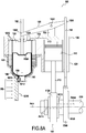
figure 1 est une en perspective d'un mode de réalisation d'un moteur solaire à expansion de fluide conforme à l'invention; - les
figure 2A et2B sont des vues éclatées du moteur de lafigure 1 ; - la
figure 3 est une vue en perspective agrandie du dispositif de chauffage solaire de fluide représenté sur lesfigures 2A et2B ; - les
figures 4A et 4B sont des vues respectivement en perspective et en coupe de l'arbre représenté sur lesfigures 2A et2B ; - la
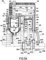
figure 5A est une vue en coupe d'un module d'actionnement du moteur de lafigure 1 ; - la
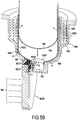
figure 5B est une vue de détail d'une partie du module d'actionnement de lafigure 5A ; - les
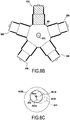
figures 6A à 6C, 7A à 7C, 8A à 8C et 9A à 9C montrent le fonctionnement du moteur de lafigure 1 sur un tour de celui-ci; - la
figure 10 montre un système utilisant le moteur de lafigure 1 qui permet de récupérer l'énergie produite par le moteur; - la
figure 11 montre le système de lafigure 10 lorsque le moteur est soumis à un rayonnement solaire.
- the
figure 1 is a perspective view of an embodiment of a fluid expansion solar motor according to the invention; - the
figure 2A and2B are exploded views of the engine of thefigure 1 ; - the
figure 3 is an enlarged perspective view of the solar fluid heater shown infigures 2A and2B ; - the
figures 4A and 4B are views respectively in perspective and in section of the tree shown in thefigures 2A and2B ; - the
figure 5A is a sectional view of a module for actuating the motor of thefigure 1 ; - the
figure 5B is a detail view of part of the actuation module of thefigure 5A ; - the
figures 6A to 6C, 7A to 7C, 8A to 8C and 9A to 9C show the operation of the engine of thefigure 1 on one turn of it; - the
figure 10 shows a system using the engine of thefigure 1 which makes it possible to recover the energy produced by the engine; - the
figure 11 shows the system offigure 10 when the engine is subjected to solar radiation.
La
Comme illustré sur les
Chaque chemise 111, respectivement 211, 311, 411 et 511 est fixée dans un logement 121, respectivement 221, 321, 421 et 521 d'un bloc-cylindres 120, respectivement 220, 320, 420 et 520 comportant sur sa surface extérieure des ailettes de refroidissement 122, respectivement 222, 322, 422 et 522.Each
Chaque bloc-cylindres 120, respectivement 220, 320, 420 et 520 est fermé dans sa partie supérieure par une plaque 130, respectivement 230, 330, 430 et 530 comportant des ailettes de refroidissement 131, respectivement 231, 331, 431 et 531 et un capot 140, respectivement 240, 340, 440 et 540 comportant également des ailettes de refroidissement 141, respectivement 241, 341, 441 et 541.Each
Chaque module d'actionnement 100, respectivement 200, 300, 400 et 500, comprend en outre un piston de déplacement 150, respectivement 250, 350, 450 et 550. Chaque piston de déplacement 150, respectivement 250, 350, 450 et 550 est mobile dans une chemise 151, respectivement 251, 351, 451 et 551 formée chacune par la réunion de deux éléments 1510/1511, respectivement 2510/2511, 3510/3511, 4510/4511 et 5510/5511. L'élément 1510, respectivement 2510, 3510, 4510 et 5510 de la chemise 151, respectivement 251, 351, 451 et 551 est logé dans un carter cylindrique 160, respectivement 260, 360, 460 et 560. L'élément 1511, respectivement 2511, 3511, 4511 et 5511 de la chemise 151, respectivement 251, 351, 451 et 551 est fixé dans un logement 123, respectivement 223, 323, 423 et 523 du bloc-cylindres 120, respectivement 220, 320, 420 et 520. Le logement 123, respectivement 223, 323, 423 et 523 comporte un dispositif de refroidissement 1230, respectivement 2230, 3230, 4230 et 5230 constitué ici par des ailettes de refroidissement. Comme illustré pour le logement 123 sur la
Chaque piston de déplacement 150, respectivement 250, 350, 450 et 550 est relié à une tige de commande 152, respectivement 252, 352, 452 et 552, elle-même reliée à une première extrémité 1530, respectivement 2530, 3530, 4530 et 5530 d'un basculeur 153, respectivement 253, 353, 453 et 553. La seconde extrémité 1531, respectivement 2531, 3531, 4531 et 5531 du basculeur 153, respectivement, 253, 353, 453 et 553 est reliée à une tige de bascule 154, respectivement 254, 354, 454 et 554. Chaque basculeur 153, respectivement, 253, 353, 453 et 553 comprend un axe 1532, respectivement 2532, 3532, 4532 et 5532 monté sur un support 132, respectivement 232, 332, 432 et 532 présent sur la plaque 130, respectivement 230, 330, 430 et 530. Chaque basculeur 153, respectivement, 253, 353, 453 et 553 est logé dans une cavité 142, respectivement, 242, 242, 442 et 542 ménagée dans le capot 140, respectivement 240, 340, 440 et 540.Each
La tige de bascule 154, qui correspond à la tige de bascule maîtresse, comporte à son extrémité opposée à celle reliée à la seconde extrémité 1531 du basculeur 153 un suiveur de came 1540 sur lequel sont montées de manière articulée les tiges de bascule 254, 354, 454 et 554. Le suiveur de came 1540 est monté sur une came 6120 présente sur l'arbre 610, un roulement 1541 étant interposé entre la came 6120 et le suiveur de came 1540.The
La partie de l'arbre comportant le vilebrequin 611 et la came 6120 est enfermée dans le carter moteur 601 qui est formé d'une enceinte 6012, d'un couvercle 6010 et d'un fond 6015. L'enceinte 6012 comporte des premières ouvertures 6013 pour le passage des tiges de bascule 154, 254, 354, 454 et 554 et des deuxièmes ouvertures 6014 pour le passage des bielles 112, 212, 312, 412 et 512. Le fond du carter 6015 comportent un évidement 6016 formant un palier pour supporter l'extrémité 610a de l'arbre central 610 via un roulement 6017. Le couvercle 6010 comporte une ouverture centrale 6011 pour le passage de l'autre extrémité 601b de l'arbre 610, l'arbre étant supporté dans l'ouverture 6011 par un roulement 6018.The part of the shaft comprising the
Comme illustré sur la
La
Comme illustré sur la
Le module d'actionnement 100 comporte un circuit fermé de circulation de fluide 180 formé entre le boîtier 6210 et la chambre de travail 113, ce circuit étant formé par un interstice circulaire 165 correspondant à un jeu entre l'élément 1510 de la chemise 151 et le carter 160, une enceinte cylindrique 162 comprise également entre l'élément 1510 de la chemise 151 et le carter 160, le dispositif de refroidissement 1230, la chambre basse température 1550, un évidement 133 ménagé dans la plaque 130 et la chambre haute température 1551. Le volume interne du module d'actionnement, constitué par le boîtier 6210, la chambre de travail 113 et le circuit de circulation de fluide 180, est rempli avec un fluide gazeux qui se dilate lorsqu'on élève sa température, c'est-à-dire un fluide ayant un coefficient de dilatation thermique élevé. Un tel fluide peut-être notamment choisi parmi les fluides suivant: air, hydrogène, fréon et hélium. Tout autre fluide ayant la capacité de se dilater suffisamment pour entraîner chaque module d'actionnement peut être utilisé dans le moteur de l'invention. Chaque module d'actionnement comprend au moins une valve permettant de vidanger et de remplir chaque circuit de circulation avec le fluide désiré (non représentée sur les figures).The
Le piston moteur 110 et le piston de déplacement 150 sont disposés de façon adjacente dans un même plan parallèle à l'axe de l'arbre central en particulier grâce à l'utilisation du basculeur 153 placé au-dessus du piston moteur 110 qui permet de disposer la tige de commande 152 et la tige de bascule 154 au plus près du piston moteur et dans le même plan que celui-ci. Grâce à cette disposition, il est possible de minimiser l'encombrement de chaque module d'actionnement et d'améliorer la compacité du moteur.The
Les
Lors des phases du cycle thermodynamique du module d'actionnement correspondant à une diminution du volume du fluide F et à la remontée du piston moteur 110, le fluide F circule depuis la chambre de travail 113 jusqu'au boîtier 6210 en passant respectivement par l'évidement 133, le dispositif de refroidissement 1230, le régénérateur 163, l'interstice circulaire 165 et la sortie 6213 du boîtier 6210. Lors de la remontée du piston de déplacement 150, une partie du fluide F présent dans la chambre basse température est amenée dans le boîtier 6210 par le même chemin.During the phases of the thermodynamic cycle of the actuation module corresponding to a decrease in the volume of the fluid F and the rise of the
Comme décrit précédemment, le piston moteur 110 est relié au maneton 6110 solidaire de l'arbre 610 par sa bielle 112 tandis que le piston de déplacement est relié à la came 6120 également solidaire de l'arbre 610 par la tige de commande 152, le basculeur 153 et la tige de bascule 154. Comme illustrés sur les
La structure et le fonctionnement des modules d'actionnement 200, 300, 400 et 500 sont identiques à ceux qui viennent d'être décrits pour le module d'actionnement 100 et ne seront pas décrites à nouveau par souci de simplification. Les modules d'actionnement 200, 300, 400 et 500 diffèrent simplement du module d'actionnement 100 en ce que les bielles 212, 312, 412 et 512 des pistons moteurs 210, 310, 410 et 510 ainsi que les tiges de bascules 254, 354, 454 et 554 des pistons de déplacement 250, 350, 450 et 550 sont respectivement des bielles et des tiges de commandes suiveuses alors que la bielle 112 et la tige de commande 154 du module d'actionnement 100 sont respectivement une bielle et une tige de commande maîtresses.The structure and operation of the
On décrit maintenant le fonctionnement du moteur 600 sur un tour moteur (360°), c'est-à-dire les positions du moteur 600 ainsi que celles des éléments du module d'actionnement 100 respectivement au départ d'un tour (0°), après un quart de tour (90°), après une moitié de tour (180°), après trois-quarts de tour (270°) et après un tour complet (360°).We now describe the operation of the
Au départ du tour (
La phase de chauffage isochore est suivie par la phase de détente isotherme. Le fluide présent notamment dans le boîtier 6210 se dilate alors sous l'effet de la chaleur reçue et sort de celui-ci par la sortie 6213. Le gaz traverse le régénérateur 163 où il cède une part très importante de sa chaleur. Le fluide poursuit son parcours à travers le dispositif de refroidissement 1230 et arrive dans la chambre de travail 113. La pression du fluide diminue tandis que son volume augmente en particulier dans la chambre de travail 113, ce qui entraîne un effort de poussée sur le piston moteur 110 qui amorce un mouvement de descente en même temps que le piston de déplacement. La bielle 112 du piston moteur 110 exerce alors une force de poussée sur le maneton 6110 via sa tête 1120. Cette poussée contribue à la mise en rotation du moteur 600.The isochoric heating phase is followed by the isothermal expansion phase. The fluid present in particular in the
Après un quart de tour (
La phase de détente isotherme est alors suivie par la phase de refroidissement isochore du fluide dans le module d'actionnement qui correspond à une baisse de la pression et de la température du fluide.The isothermal expansion phase is then followed by the isochoric cooling phase of the fluid in the actuation module which corresponds to a drop in the pressure and temperature of the fluid.
Après une moitié de tour (
La phase de refroidissement isochore est suivie par la phase de compression isothermique dans laquelle la pression du fluide augmente tandis que son volume diminue.The isochoric cooling phase is followed by the isothermal compression phase in which the pressure of the fluid increases while its volume decreases.
Après trois-quarts de tour (
Après un tour complet, le moteur 600 et le module d'actionnement se retrouvent dans la configuration des
Le moteur selon l'invention est très peu polluant car il n'utilise pas de moyens de combustion interne ou externe pour son entraînement et ne rejette donc pas de gaz de combustion. Le moteur de l'invention demande également peu d'entretien et a un fonctionnement très silencieux.The engine according to the invention is very low polluting because it does not use internal or external combustion means for its drive and therefore does not reject combustion gas. The engine of the invention also requires little maintenance and operates very quietly.
En outre, chaque module d'actionnement et, par conséquent, le moteur présentent une structure compacte notamment grâce à la présence d'un circuit de circulation de fluide reliant le dispositif de chauffage solaire à la chambre de travail du piston moteur.In addition, each actuation module and, consequently, the motor have a compact structure in particular thanks to the presence of a fluid circulation circuit connecting the solar heating device to the working chamber of the motor piston.
Par ailleurs, dans le moteur de l'invention, chaque module d'actionnement, dont le fonctionnement est basé sur le principe du moteur Stirling, est en rotation permanente autour de l'arbre central, ce qui permet de créer une ventilation naturelle, en particulier sur la paroi externe de la chambre de travail du piston moteur, et d'accélérer, par conséquent, le refroidissement du fluide en fin de cycle thermodynamique. On améliore ainsi le rendement du moteur.Furthermore, in the engine of the invention, each actuation module, the operation of which is based on the principle of the Stirling engine, is in permanent rotation around the central shaft, which makes it possible to create natural ventilation, in particularly on the outer wall of the working chamber of the engine piston, and consequently accelerate the cooling of the fluid at the end of the thermodynamic cycle. This improves the efficiency of the engine.
La
Sur la
Claims (8)
- A hot fluid expansion engine (600) comprising a central shaft (610) and a plurality of actuator modules (100, 200, 300, 400, 500) arranged in a star configuration around the central shaft (610), each module (100; 200; 300; 400; 500) comprising:• a drive piston (110; 210; 310; 410; 510) movable in a first enclosure (111), the drive piston (110) defining a working chamber (113) of variable volume in said first enclosure; and• a displacement piston (150; 250; 350; 450; 550) movable in a second enclosure (155), the displacement piston (150) separating a low temperature chamber (1150) of variable volume from a high temperature chamber (1151) of variable volume in said second enclosure, the low temperature chamber (1150) communicating with the working chamber (113);the drive piston (110) and the displacement piston (150) of each actuator module (100) being connected to the central shaft (610) via respective first and second eccentric transmission devices (1120, 112; 1540, 154, 153, 152), each suitable for causing the corresponding piston to perform reciprocating motion in translation, the motion of the drive piston having a phase lag of 90° relative to the motion of the displacement piston, each module (100; 200; 300; 400; 500) being driven in rotation about a central shaft (610) so as to accelerate the cooling of the fluid in the working chamber;
wherein each actuator module (100; 200; 300; 400; 500), the drive piston (110; 210; 310; 410; 510) and the displacement piston (150; 250; 350; 450; 550) are arranged in adjacent manner in a common plane perpendicular to the axis of the central shaft (610),
characterized in that said the engine further includes a fluid heater device (620), each high temperature chamber (1551) communicating with the fluid heater device (620) and each working chamber (113) being connected to said fluid heater device via a fluid circulation circuit (180), and in that the fluid circulation circuit (180) of each actuator module (100) includes a gas regenerator (163) extending around the high temperature chamber (1551), and in that each displacement piston (150; 250; 350; 450; 550) is connected to a first end of a rocker (153; 253; 353; 453; 553) via a guide rod (152; 252; 352; 452; 552), the second end of the rocker being connected to one end of a control rod (154; 254; 354; 454; 554), the opposite end of the control rod being connected to a cam follower (1540) mounted on a cam (6120) secured to the central shaft (610). - An engine according to claim 1, characterized in that each actuator module (100; 200; 300; 400; 500) comprises a cylinder block (120; 220; 320; 420; 520) having an internal housing (121; 221; 321; 421; 521) corresponding to the working chamber, said cylinder block having cooling fins (122; 222; 322; 422; 522) on its outside surface.
- An engine according to claim 1 or claim 2, characterized in that the fluid circulation circuit (180) of each actuator module (100) comprises a heat dissipater (1230) extending around the low temperature chamber (1550).
- An engine according to any one of claims 1 to 3, characterized in that the fluid heater device (620) comprises a plurality of collector unit (6210; 6220; 6230; 6240; 6250) each enclosing an array of channels (6211; 6221; 6231; 6241; 6251) extending between an inlet (6212; 6222; 6232; 6242; 6252) and an outlet (6213; 6223; 6233; 6243; 6253), the inlet (6212; 6222; 6232; 6242; 6252) of each unit (6210; 6220; 6230; 6240; 6250) being connected to the high temperature chamber (1551) of a corresponding actuator module (100; 200; 300; 400; 500), and the outlet (6213; 6223; 6233; 6243; 6253) of said unit being connected to the fluid circulation circuit (180) of said corresponding actuator module (100).
- An engine according to any one of claims 1 to 4, characterized in that it includes a solar radiation concentrator device (900) suitable for concentrating solar rays (Rs) on the collector unit (6210; 6220; 6230; 6240; 6250) of the fluid heater device (120).
- An engine according to any one of claims 1 to 4, characterized in that it includes heater means suitable for transmitting heat to the collector unit (6210; 6220; 6230; 6240; 6250) of the fluid heater device (620).
- An engine according to any one of claims 1 to 6, characterized in that each drive piston (110; 210; 310; 410; 510) is connected to one end of a connecting rod (112; 212; 312; 412; 512), the opposite end of the connecting rod being connected to a head (1120) mounted on a crankpin (6110) of a crankshaft (611) present on the central shaft (610).
- An engine according to any one of claims 1 to 7, characterized in that each actuator module (100; 200; 300; 400; 500) contains a gaseous fluid selected from at least one of the following gaseous fluids: air, hydrogen, Freon, and helium.
Priority Applications (3)
| Application Number | Priority Date | Filing Date | Title |
|---|---|---|---|
| EP13169300.4A EP2808528B1 (en) | 2013-05-27 | 2013-05-27 | Fluid expansion motor |
| ES13169300T ES2827320T3 (en) | 2013-05-27 | 2013-05-27 | Fluid expansion motor |
| US14/287,313 US9598959B2 (en) | 2013-05-27 | 2014-05-27 | Fluid expansion engine |
Applications Claiming Priority (1)
| Application Number | Priority Date | Filing Date | Title |
|---|---|---|---|
| EP13169300.4A EP2808528B1 (en) | 2013-05-27 | 2013-05-27 | Fluid expansion motor |
Publications (2)
| Publication Number | Publication Date |
|---|---|
| EP2808528A1 EP2808528A1 (en) | 2014-12-03 |
| EP2808528B1 true EP2808528B1 (en) | 2020-08-05 |
Family
ID=48534200
Family Applications (1)
| Application Number | Title | Priority Date | Filing Date |
|---|---|---|---|
| EP13169300.4A Active EP2808528B1 (en) | 2013-05-27 | 2013-05-27 | Fluid expansion motor |
Country Status (3)
| Country | Link |
|---|---|
| US (1) | US9598959B2 (en) |
| EP (1) | EP2808528B1 (en) |
| ES (1) | ES2827320T3 (en) |
Families Citing this family (2)
| Publication number | Priority date | Publication date | Assignee | Title |
|---|---|---|---|---|
| JP2019052563A (en) * | 2017-09-13 | 2019-04-04 | 和広 千野 | Stirling engine and Stirling refrigerator |
| DE102019131363B3 (en) * | 2019-11-20 | 2020-10-01 | Friedrich Baum | Hot air engine with a rotating cylinder arrangement around a fixed crankshaft |
Citations (1)
| Publication number | Priority date | Publication date | Assignee | Title |
|---|---|---|---|---|
| US20020124561A1 (en) * | 2001-03-12 | 2002-09-12 | Masaki Ban | Stirling engine |
Family Cites Families (20)
| Publication number | Priority date | Publication date | Assignee | Title |
|---|---|---|---|---|
| BE523269A (en) * | ||||
| US751694A (en) * | 1904-02-09 | sheaeee | ||
| US1316346A (en) * | 1919-09-16 | augustine | ||
| US1382611A (en) * | 1917-08-15 | 1921-06-28 | Benjamin F Augustine | Rotary gas-engine |
| US1300916A (en) * | 1917-11-07 | 1919-04-15 | Bernard M Beach | Internal-combustion engine. |
| CH442865A (en) * | 1966-02-23 | 1967-08-31 | Wyssbrod Hans | Piston engine with rotating cylinders |
| US3657877A (en) * | 1971-02-01 | 1972-04-25 | Thermo Electron Corp | Tidal regenerator heat engine |
| US3857371A (en) * | 1973-06-04 | 1974-12-31 | T Gibson | Rotary internal combustion engine |
| US4642988A (en) * | 1981-08-14 | 1987-02-17 | New Process Industries, Inc. | Solar powered free-piston Stirling engine |
| US4677825A (en) * | 1986-06-12 | 1987-07-07 | Fellows Oscar L | Thermomotor |
| US5177968A (en) * | 1992-05-20 | 1993-01-12 | Fellows Oscar L | Radial hot gas engine |
| US5303679A (en) * | 1993-08-12 | 1994-04-19 | Vicente Gamon | Rotary internal combustion engine |
| DE4336975A1 (en) * | 1993-10-29 | 1995-05-04 | Erno Raumfahrttechnik Gmbh | Power generation facility |
| US5390496A (en) * | 1994-03-04 | 1995-02-21 | El Affaqui; Thami | Stirling engine with annular cam |
| US5884481A (en) * | 1997-07-14 | 1999-03-23 | Stm Corporation | Heat engine heater assembly |
| US20030226525A1 (en) * | 2002-06-11 | 2003-12-11 | Warren Edward Lawrence | Warren cycle internal combustion engine with heat exchanger |
| US6979911B2 (en) * | 2003-05-08 | 2005-12-27 | United Technologies Corporation | Method and apparatus for solar power conversion |
| DE102004059928B4 (en) * | 2004-12-13 | 2007-12-13 | Robert Welle | Stirling radial engine |
| DE102009023024A1 (en) * | 2009-05-28 | 2010-12-09 | Schliebe, Günther | Stirling engine assembly |
| EP2434135A1 (en) * | 2010-09-24 | 2012-03-28 | Neemat Frem | Rotary expansion engine |
-
2013
- 2013-05-27 EP EP13169300.4A patent/EP2808528B1/en active Active
- 2013-05-27 ES ES13169300T patent/ES2827320T3/en active Active
-
2014
- 2014-05-27 US US14/287,313 patent/US9598959B2/en active Active
Patent Citations (1)
| Publication number | Priority date | Publication date | Assignee | Title |
|---|---|---|---|---|
| US20020124561A1 (en) * | 2001-03-12 | 2002-09-12 | Masaki Ban | Stirling engine |
Also Published As
| Publication number | Publication date |
|---|---|
| ES2827320T3 (en) | 2021-05-20 |
| US20140345269A1 (en) | 2014-11-27 |
| EP2808528A1 (en) | 2014-12-03 |
| US9598959B2 (en) | 2017-03-21 |
Similar Documents
| Publication | Publication Date | Title |
|---|---|---|
| EP2031234B1 (en) | Generation of electricity in a turbomachine by means of a stirling engine | |
| CA2751395C (en) | Thermoelectric generation for a gas turbine | |
| EP2556236B1 (en) | Stirling machine | |
| EP2434135A1 (en) | Rotary expansion engine | |
| EP2808528B1 (en) | Fluid expansion motor | |
| US9086013B2 (en) | Gerotor rotary Stirling cycle engine | |
| FR2681906A1 (en) | Centrifugal pump for a combustion engine coolant circuit | |
| BE897859A (en) | ROTARY MOTOR | |
| EP3099919B1 (en) | External combustion engine | |
| FR2482190A1 (en) | POWER AMPLIFIER FOR HEAT ENGINES OR OTHER | |
| FR3025254B1 (en) | MOTOR WITH DIFFERENTIAL EVAPORATION PRESSURES | |
| WO2014080130A1 (en) | Unit for converting thermal energy into hydraulic energy | |
| FR3114621A3 (en) | Stirling cycle engine | |
| FR2817592A1 (en) | Engine with external heat source and crosswise working and transfer pistons in each cylinder generating thermodynamic cycle without compression | |
| FR3140653A1 (en) | DEVICE FOR ENERGY CONVERSION | |
| FR2972481A1 (en) | Alternative heat engine for driving e.g. two-stage variable displacement compressor, has control unit controlling opening and closing of flow channels according to predetermined operation cycle | |
| FR2998007A1 (en) | INTEGRATED VALVE PISTON | |
| FR2950391A1 (en) | Internal combustion heat engine e.g. petrol engine, has piston connected to crankshaft by rod in form of knuckle joint with adjustable spacing, where extension length between attachment point of rod to piston and crankshaft is adjusted | |
| FR3081032A3 (en) | EXTERNAL HEAT ENGINE | |
| FR2957137A1 (en) | Heat exchanger module for stirling engine utilized for boilers, has two exchangers, where one of exchangers is placed on two sides of other heat exchanger and operated at temperature different from that of former exchanger | |
| FR3031770A1 (en) | THERMAL MOTOR CONDENSATION | |
| WO2011128520A1 (en) | Fuelless combustion engine suited notably to the automotive and nuclear fields | |
| FR2950935A1 (en) | Stirling engine for converting heat energy into electric or mechanical energy, has cavity with displacers, where another cavity is provided with working piston that is displaced by contraction and relaxation of working gas in former cavity | |
| BE353917A (en) | ||
| FR2928230A1 (en) | Electro-thermal generator for recharging battery in propulsion system of e.g. hybrid car, has exhaust valve, ignition or injection system and valve following cycle at two or four strokes of internal combustion engines |
Legal Events
| Date | Code | Title | Description |
|---|---|---|---|
| PUAI | Public reference made under article 153(3) epc to a published international application that has entered the european phase |
Free format text: ORIGINAL CODE: 0009012 |
|
| 17P | Request for examination filed |
Effective date: 20130527 |
|
| AK | Designated contracting states |
Kind code of ref document: A1 Designated state(s): AL AT BE BG CH CY CZ DE DK EE ES FI FR GB GR HR HU IE IS IT LI LT LU LV MC MK MT NL NO PL PT RO RS SE SI SK SM TR |
|
| AX | Request for extension of the european patent |
Extension state: BA ME |
|
| R17P | Request for examination filed (corrected) |
Effective date: 20150529 |
|
| RBV | Designated contracting states (corrected) |
Designated state(s): AL AT BE BG CH CY CZ DE DK EE ES FI FR GB GR HR HU IE IS IT LI LT LU LV MC MK MT NL NO PL PT RO RS SE SI SK SM TR |
|
| STAA | Information on the status of an ep patent application or granted ep patent |
Free format text: STATUS: EXAMINATION IS IN PROGRESS |
|
| 17Q | First examination report despatched |
Effective date: 20180111 |
|
| REG | Reference to a national code |
Ref country code: DE Ref legal event code: R079 Ref document number: 602013071258 Country of ref document: DE Free format text: PREVIOUS MAIN CLASS: F02G0001044000 Ipc: F01B0009060000 |
|
| GRAP | Despatch of communication of intention to grant a patent |
Free format text: ORIGINAL CODE: EPIDOSNIGR1 |
|
| STAA | Information on the status of an ep patent application or granted ep patent |
Free format text: STATUS: GRANT OF PATENT IS INTENDED |
|
| RIC1 | Information provided on ipc code assigned before grant |
Ipc: F03G 6/04 20060101ALI20200214BHEP Ipc: F01B 1/06 20060101ALI20200214BHEP Ipc: F02G 1/044 20060101ALI20200214BHEP Ipc: F02G 1/055 20060101ALI20200214BHEP Ipc: F01B 9/06 20060101AFI20200214BHEP Ipc: F01B 9/02 20060101ALI20200214BHEP Ipc: F03G 6/06 20060101ALI20200214BHEP |
|
| INTG | Intention to grant announced |
Effective date: 20200303 |
|
| GRAS | Grant fee paid |
Free format text: ORIGINAL CODE: EPIDOSNIGR3 |
|
| GRAA | (expected) grant |
Free format text: ORIGINAL CODE: 0009210 |
|
| STAA | Information on the status of an ep patent application or granted ep patent |
Free format text: STATUS: THE PATENT HAS BEEN GRANTED |
|
| AK | Designated contracting states |
Kind code of ref document: B1 Designated state(s): AL AT BE BG CH CY CZ DE DK EE ES FI FR GB GR HR HU IE IS IT LI LT LU LV MC MK MT NL NO PL PT RO RS SE SI SK SM TR |
|
| REG | Reference to a national code |
Ref country code: GB Ref legal event code: FG4D Free format text: NOT ENGLISH |
|
| REG | Reference to a national code |
Ref country code: CH Ref legal event code: EP |
|
| REG | Reference to a national code |
Ref country code: AT Ref legal event code: REF Ref document number: 1298949 Country of ref document: AT Kind code of ref document: T Effective date: 20200815 |
|
| REG | Reference to a national code |
Ref country code: DE Ref legal event code: R096 Ref document number: 602013071258 Country of ref document: DE |
|
| REG | Reference to a national code |
Ref country code: IE Ref legal event code: FG4D Free format text: LANGUAGE OF EP DOCUMENT: FRENCH |
|
| REG | Reference to a national code |
Ref country code: CH Ref legal event code: NV Representative=s name: MICHELI AND CIE SA, CH |
|
| REG | Reference to a national code |
Ref country code: GR Ref legal event code: EP Ref document number: 20200402927 Country of ref document: GR Effective date: 20201116 |
|
| REG | Reference to a national code |
Ref country code: LT Ref legal event code: MG4D |
|
| REG | Reference to a national code |
Ref country code: NL Ref legal event code: MP Effective date: 20200805 |
|
| REG | Reference to a national code |
Ref country code: AT Ref legal event code: MK05 Ref document number: 1298949 Country of ref document: AT Kind code of ref document: T Effective date: 20200805 |
|
| PG25 | Lapsed in a contracting state [announced via postgrant information from national office to epo] |
Ref country code: LT Free format text: LAPSE BECAUSE OF FAILURE TO SUBMIT A TRANSLATION OF THE DESCRIPTION OR TO PAY THE FEE WITHIN THE PRESCRIBED TIME-LIMIT Effective date: 20200805 Ref country code: FI Free format text: LAPSE BECAUSE OF FAILURE TO SUBMIT A TRANSLATION OF THE DESCRIPTION OR TO PAY THE FEE WITHIN THE PRESCRIBED TIME-LIMIT Effective date: 20200805 Ref country code: SE Free format text: LAPSE BECAUSE OF FAILURE TO SUBMIT A TRANSLATION OF THE DESCRIPTION OR TO PAY THE FEE WITHIN THE PRESCRIBED TIME-LIMIT Effective date: 20200805 Ref country code: HR Free format text: LAPSE BECAUSE OF FAILURE TO SUBMIT A TRANSLATION OF THE DESCRIPTION OR TO PAY THE FEE WITHIN THE PRESCRIBED TIME-LIMIT Effective date: 20200805 Ref country code: PT Free format text: LAPSE BECAUSE OF FAILURE TO SUBMIT A TRANSLATION OF THE DESCRIPTION OR TO PAY THE FEE WITHIN THE PRESCRIBED TIME-LIMIT Effective date: 20201207 Ref country code: BG Free format text: LAPSE BECAUSE OF FAILURE TO SUBMIT A TRANSLATION OF THE DESCRIPTION OR TO PAY THE FEE WITHIN THE PRESCRIBED TIME-LIMIT Effective date: 20201105 Ref country code: NO Free format text: LAPSE BECAUSE OF FAILURE TO SUBMIT A TRANSLATION OF THE DESCRIPTION OR TO PAY THE FEE WITHIN THE PRESCRIBED TIME-LIMIT Effective date: 20201105 Ref country code: AT Free format text: LAPSE BECAUSE OF FAILURE TO SUBMIT A TRANSLATION OF THE DESCRIPTION OR TO PAY THE FEE WITHIN THE PRESCRIBED TIME-LIMIT Effective date: 20200805 |
|
| PG25 | Lapsed in a contracting state [announced via postgrant information from national office to epo] |
Ref country code: PL Free format text: LAPSE BECAUSE OF FAILURE TO SUBMIT A TRANSLATION OF THE DESCRIPTION OR TO PAY THE FEE WITHIN THE PRESCRIBED TIME-LIMIT Effective date: 20200805 Ref country code: RS Free format text: LAPSE BECAUSE OF FAILURE TO SUBMIT A TRANSLATION OF THE DESCRIPTION OR TO PAY THE FEE WITHIN THE PRESCRIBED TIME-LIMIT Effective date: 20200805 Ref country code: NL Free format text: LAPSE BECAUSE OF FAILURE TO SUBMIT A TRANSLATION OF THE DESCRIPTION OR TO PAY THE FEE WITHIN THE PRESCRIBED TIME-LIMIT Effective date: 20200805 Ref country code: LV Free format text: LAPSE BECAUSE OF FAILURE TO SUBMIT A TRANSLATION OF THE DESCRIPTION OR TO PAY THE FEE WITHIN THE PRESCRIBED TIME-LIMIT Effective date: 20200805 Ref country code: IS Free format text: LAPSE BECAUSE OF FAILURE TO SUBMIT A TRANSLATION OF THE DESCRIPTION OR TO PAY THE FEE WITHIN THE PRESCRIBED TIME-LIMIT Effective date: 20201205 |
|
| PG25 | Lapsed in a contracting state [announced via postgrant information from national office to epo] |
Ref country code: CZ Free format text: LAPSE BECAUSE OF FAILURE TO SUBMIT A TRANSLATION OF THE DESCRIPTION OR TO PAY THE FEE WITHIN THE PRESCRIBED TIME-LIMIT Effective date: 20200805 Ref country code: DK Free format text: LAPSE BECAUSE OF FAILURE TO SUBMIT A TRANSLATION OF THE DESCRIPTION OR TO PAY THE FEE WITHIN THE PRESCRIBED TIME-LIMIT Effective date: 20200805 Ref country code: EE Free format text: LAPSE BECAUSE OF FAILURE TO SUBMIT A TRANSLATION OF THE DESCRIPTION OR TO PAY THE FEE WITHIN THE PRESCRIBED TIME-LIMIT Effective date: 20200805 Ref country code: SM Free format text: LAPSE BECAUSE OF FAILURE TO SUBMIT A TRANSLATION OF THE DESCRIPTION OR TO PAY THE FEE WITHIN THE PRESCRIBED TIME-LIMIT Effective date: 20200805 Ref country code: RO Free format text: LAPSE BECAUSE OF FAILURE TO SUBMIT A TRANSLATION OF THE DESCRIPTION OR TO PAY THE FEE WITHIN THE PRESCRIBED TIME-LIMIT Effective date: 20200805 |
|
| REG | Reference to a national code |
Ref country code: DE Ref legal event code: R097 Ref document number: 602013071258 Country of ref document: DE |
|
| REG | Reference to a national code |
Ref country code: ES Ref legal event code: FG2A Ref document number: 2827320 Country of ref document: ES Kind code of ref document: T3 Effective date: 20210520 |
|
| PG25 | Lapsed in a contracting state [announced via postgrant information from national office to epo] |
Ref country code: AL Free format text: LAPSE BECAUSE OF FAILURE TO SUBMIT A TRANSLATION OF THE DESCRIPTION OR TO PAY THE FEE WITHIN THE PRESCRIBED TIME-LIMIT Effective date: 20200805 |
|
| PLBE | No opposition filed within time limit |
Free format text: ORIGINAL CODE: 0009261 |
|
| STAA | Information on the status of an ep patent application or granted ep patent |
Free format text: STATUS: NO OPPOSITION FILED WITHIN TIME LIMIT |
|
| PG25 | Lapsed in a contracting state [announced via postgrant information from national office to epo] |
Ref country code: SK Free format text: LAPSE BECAUSE OF FAILURE TO SUBMIT A TRANSLATION OF THE DESCRIPTION OR TO PAY THE FEE WITHIN THE PRESCRIBED TIME-LIMIT Effective date: 20200805 |
|
| 26N | No opposition filed |
Effective date: 20210507 |
|
| PG25 | Lapsed in a contracting state [announced via postgrant information from national office to epo] |
Ref country code: SI Free format text: LAPSE BECAUSE OF FAILURE TO SUBMIT A TRANSLATION OF THE DESCRIPTION OR TO PAY THE FEE WITHIN THE PRESCRIBED TIME-LIMIT Effective date: 20200805 |
|
| PG25 | Lapsed in a contracting state [announced via postgrant information from national office to epo] |
Ref country code: LU Free format text: LAPSE BECAUSE OF NON-PAYMENT OF DUE FEES Effective date: 20210527 Ref country code: MC Free format text: LAPSE BECAUSE OF FAILURE TO SUBMIT A TRANSLATION OF THE DESCRIPTION OR TO PAY THE FEE WITHIN THE PRESCRIBED TIME-LIMIT Effective date: 20200805 |
|
| PG25 | Lapsed in a contracting state [announced via postgrant information from national office to epo] |
Ref country code: IE Free format text: LAPSE BECAUSE OF NON-PAYMENT OF DUE FEES Effective date: 20210527 |
|
| PGFP | Annual fee paid to national office [announced via postgrant information from national office to epo] |
Ref country code: IT Payment date: 20220510 Year of fee payment: 10 Ref country code: GB Payment date: 20220519 Year of fee payment: 10 Ref country code: FR Payment date: 20220420 Year of fee payment: 10 Ref country code: ES Payment date: 20220602 Year of fee payment: 10 Ref country code: DE Payment date: 20220511 Year of fee payment: 10 |
|
| PGFP | Annual fee paid to national office [announced via postgrant information from national office to epo] |
Ref country code: GR Payment date: 20220518 Year of fee payment: 10 Ref country code: CH Payment date: 20220530 Year of fee payment: 10 Ref country code: BE Payment date: 20220520 Year of fee payment: 10 |
|
| REG | Reference to a national code |
Ref country code: DE Ref legal event code: R082 Ref document number: 602013071258 Country of ref document: DE Representative=s name: CBDL PATENTANWAELTE GBR, DE |
|
| PG25 | Lapsed in a contracting state [announced via postgrant information from national office to epo] |
Ref country code: HU Free format text: LAPSE BECAUSE OF FAILURE TO SUBMIT A TRANSLATION OF THE DESCRIPTION OR TO PAY THE FEE WITHIN THE PRESCRIBED TIME-LIMIT; INVALID AB INITIO Effective date: 20130527 |
|
| PG25 | Lapsed in a contracting state [announced via postgrant information from national office to epo] |
Ref country code: CY Free format text: LAPSE BECAUSE OF FAILURE TO SUBMIT A TRANSLATION OF THE DESCRIPTION OR TO PAY THE FEE WITHIN THE PRESCRIBED TIME-LIMIT Effective date: 20200805 |
|
| REG | Reference to a national code |
Ref country code: DE Ref legal event code: R119 Ref document number: 602013071258 Country of ref document: DE |
|
| REG | Reference to a national code |
Ref country code: CH Ref legal event code: PL |
|
| PG25 | Lapsed in a contracting state [announced via postgrant information from national office to epo] |
Ref country code: GR Free format text: LAPSE BECAUSE OF NON-PAYMENT OF DUE FEES Effective date: 20231208 |
|
| GBPC | Gb: european patent ceased through non-payment of renewal fee |
Effective date: 20230527 |
|
| REG | Reference to a national code |
Ref country code: BE Ref legal event code: MM Effective date: 20230531 |
|
| PG25 | Lapsed in a contracting state [announced via postgrant information from national office to epo] |
Ref country code: LI Free format text: LAPSE BECAUSE OF NON-PAYMENT OF DUE FEES Effective date: 20230531 Ref country code: GR Free format text: LAPSE BECAUSE OF NON-PAYMENT OF DUE FEES Effective date: 20231208 Ref country code: CH Free format text: LAPSE BECAUSE OF NON-PAYMENT OF DUE FEES Effective date: 20230531 |