EP2808528B1 - Motor mit Flüssigkeitsausdehnung - Google Patents
Motor mit Flüssigkeitsausdehnung Download PDFInfo
- Publication number
- EP2808528B1 EP2808528B1 EP13169300.4A EP13169300A EP2808528B1 EP 2808528 B1 EP2808528 B1 EP 2808528B1 EP 13169300 A EP13169300 A EP 13169300A EP 2808528 B1 EP2808528 B1 EP 2808528B1
- Authority
- EP
- European Patent Office
- Prior art keywords
- fluid
- piston
- actuator module
- central shaft
- temperature chamber
- Prior art date
- Legal status (The legal status is an assumption and is not a legal conclusion. Google has not performed a legal analysis and makes no representation as to the accuracy of the status listed.)
- Not-in-force
Links
Images







Classifications
-
- F—MECHANICAL ENGINEERING; LIGHTING; HEATING; WEAPONS; BLASTING
- F01—MACHINES OR ENGINES IN GENERAL; ENGINE PLANTS IN GENERAL; STEAM ENGINES
- F01C—ROTARY-PISTON OR OSCILLATING-PISTON MACHINES OR ENGINES
- F01C17/00—Arrangements for drive of co-operating members, e.g. for rotary piston and casing
- F01C17/04—Arrangements for drive of co-operating members, e.g. for rotary piston and casing of cam-and-follower type
-
- F—MECHANICAL ENGINEERING; LIGHTING; HEATING; WEAPONS; BLASTING
- F02—COMBUSTION ENGINES; HOT-GAS OR COMBUSTION-PRODUCT ENGINE PLANTS
- F02G—HOT GAS OR COMBUSTION-PRODUCT POSITIVE-DISPLACEMENT ENGINE PLANTS; USE OF WASTE HEAT OF COMBUSTION ENGINES; NOT OTHERWISE PROVIDED FOR
- F02G1/00—Hot gas positive-displacement engine plants
- F02G1/04—Hot gas positive-displacement engine plants of closed-cycle type
- F02G1/043—Hot gas positive-displacement engine plants of closed-cycle type the engine being operated by expansion and contraction of a mass of working gas which is heated and cooled in one of a plurality of constantly communicating expansible chambers, e.g. Stirling cycle type engines
- F02G1/044—Hot gas positive-displacement engine plants of closed-cycle type the engine being operated by expansion and contraction of a mass of working gas which is heated and cooled in one of a plurality of constantly communicating expansible chambers, e.g. Stirling cycle type engines having at least two working members, e.g. pistons, delivering power output
-
- F—MECHANICAL ENGINEERING; LIGHTING; HEATING; WEAPONS; BLASTING
- F01—MACHINES OR ENGINES IN GENERAL; ENGINE PLANTS IN GENERAL; STEAM ENGINES
- F01B—MACHINES OR ENGINES, IN GENERAL OR OF POSITIVE-DISPLACEMENT TYPE, e.g. STEAM ENGINES
- F01B1/00—Reciprocating-piston machines or engines characterised by number or relative disposition of cylinders or by being built-up from separate cylinder-crankcase elements
- F01B1/06—Reciprocating-piston machines or engines characterised by number or relative disposition of cylinders or by being built-up from separate cylinder-crankcase elements with cylinders in star or fan arrangement
-
- F—MECHANICAL ENGINEERING; LIGHTING; HEATING; WEAPONS; BLASTING
- F01—MACHINES OR ENGINES IN GENERAL; ENGINE PLANTS IN GENERAL; STEAM ENGINES
- F01B—MACHINES OR ENGINES, IN GENERAL OR OF POSITIVE-DISPLACEMENT TYPE, e.g. STEAM ENGINES
- F01B1/00—Reciprocating-piston machines or engines characterised by number or relative disposition of cylinders or by being built-up from separate cylinder-crankcase elements
- F01B1/06—Reciprocating-piston machines or engines characterised by number or relative disposition of cylinders or by being built-up from separate cylinder-crankcase elements with cylinders in star or fan arrangement
- F01B1/0603—Reciprocating-piston machines or engines characterised by number or relative disposition of cylinders or by being built-up from separate cylinder-crankcase elements with cylinders in star or fan arrangement the connection of the pistons with an element being at the outer ends of the cylinders
- F01B1/061—Reciprocating-piston machines or engines characterised by number or relative disposition of cylinders or by being built-up from separate cylinder-crankcase elements with cylinders in star or fan arrangement the connection of the pistons with an element being at the outer ends of the cylinders with two or more series radial piston-cylinder units
-
- F—MECHANICAL ENGINEERING; LIGHTING; HEATING; WEAPONS; BLASTING
- F01—MACHINES OR ENGINES IN GENERAL; ENGINE PLANTS IN GENERAL; STEAM ENGINES
- F01B—MACHINES OR ENGINES, IN GENERAL OR OF POSITIVE-DISPLACEMENT TYPE, e.g. STEAM ENGINES
- F01B1/00—Reciprocating-piston machines or engines characterised by number or relative disposition of cylinders or by being built-up from separate cylinder-crankcase elements
- F01B1/06—Reciprocating-piston machines or engines characterised by number or relative disposition of cylinders or by being built-up from separate cylinder-crankcase elements with cylinders in star or fan arrangement
- F01B1/062—Reciprocating-piston machines or engines characterised by number or relative disposition of cylinders or by being built-up from separate cylinder-crankcase elements with cylinders in star or fan arrangement the connection of the pistons with an actuating or actuated element being at the inner ends of the cylinders
-
- F—MECHANICAL ENGINEERING; LIGHTING; HEATING; WEAPONS; BLASTING
- F01—MACHINES OR ENGINES IN GENERAL; ENGINE PLANTS IN GENERAL; STEAM ENGINES
- F01B—MACHINES OR ENGINES, IN GENERAL OR OF POSITIVE-DISPLACEMENT TYPE, e.g. STEAM ENGINES
- F01B13/00—Reciprocating-piston machines or engines with rotating cylinders in order to obtain the reciprocating-piston motion
- F01B13/04—Reciprocating-piston machines or engines with rotating cylinders in order to obtain the reciprocating-piston motion with more than one cylinder
- F01B13/06—Reciprocating-piston machines or engines with rotating cylinders in order to obtain the reciprocating-piston motion with more than one cylinder in star arrangement
-
- F—MECHANICAL ENGINEERING; LIGHTING; HEATING; WEAPONS; BLASTING
- F01—MACHINES OR ENGINES IN GENERAL; ENGINE PLANTS IN GENERAL; STEAM ENGINES
- F01B—MACHINES OR ENGINES, IN GENERAL OR OF POSITIVE-DISPLACEMENT TYPE, e.g. STEAM ENGINES
- F01B13/00—Reciprocating-piston machines or engines with rotating cylinders in order to obtain the reciprocating-piston motion
- F01B13/04—Reciprocating-piston machines or engines with rotating cylinders in order to obtain the reciprocating-piston motion with more than one cylinder
- F01B13/06—Reciprocating-piston machines or engines with rotating cylinders in order to obtain the reciprocating-piston motion with more than one cylinder in star arrangement
- F01B13/068—Reciprocating-piston machines or engines with rotating cylinders in order to obtain the reciprocating-piston motion with more than one cylinder in star arrangement the connection of the pistons with an actuated or actuating element being at the inner ends of the cylinders
-
- F—MECHANICAL ENGINEERING; LIGHTING; HEATING; WEAPONS; BLASTING
- F02—COMBUSTION ENGINES; HOT-GAS OR COMBUSTION-PRODUCT ENGINE PLANTS
- F02G—HOT GAS OR COMBUSTION-PRODUCT POSITIVE-DISPLACEMENT ENGINE PLANTS; USE OF WASTE HEAT OF COMBUSTION ENGINES; NOT OTHERWISE PROVIDED FOR
- F02G1/00—Hot gas positive-displacement engine plants
- F02G1/04—Hot gas positive-displacement engine plants of closed-cycle type
- F02G1/043—Hot gas positive-displacement engine plants of closed-cycle type the engine being operated by expansion and contraction of a mass of working gas which is heated and cooled in one of a plurality of constantly communicating expansible chambers, e.g. Stirling cycle type engines
- F02G1/053—Component parts or details
- F02G1/055—Heaters or coolers
-
- F—MECHANICAL ENGINEERING; LIGHTING; HEATING; WEAPONS; BLASTING
- F03—MACHINES OR ENGINES FOR LIQUIDS; WIND, SPRING, OR WEIGHT MOTORS; PRODUCING MECHANICAL POWER OR A REACTIVE PROPULSIVE THRUST, NOT OTHERWISE PROVIDED FOR
- F03G—SPRING, WEIGHT, INERTIA OR LIKE MOTORS; MECHANICAL-POWER PRODUCING DEVICES OR MECHANISMS, NOT OTHERWISE PROVIDED FOR OR USING ENERGY SOURCES NOT OTHERWISE PROVIDED FOR
- F03G6/00—Devices for producing mechanical power from solar energy
- F03G6/02—Devices for producing mechanical power from solar energy using a single state working fluid
- F03G6/04—Devices for producing mechanical power from solar energy using a single state working fluid gaseous
-
- F—MECHANICAL ENGINEERING; LIGHTING; HEATING; WEAPONS; BLASTING
- F03—MACHINES OR ENGINES FOR LIQUIDS; WIND, SPRING, OR WEIGHT MOTORS; PRODUCING MECHANICAL POWER OR A REACTIVE PROPULSIVE THRUST, NOT OTHERWISE PROVIDED FOR
- F03G—SPRING, WEIGHT, INERTIA OR LIKE MOTORS; MECHANICAL-POWER PRODUCING DEVICES OR MECHANISMS, NOT OTHERWISE PROVIDED FOR OR USING ENERGY SOURCES NOT OTHERWISE PROVIDED FOR
- F03G6/00—Devices for producing mechanical power from solar energy
- F03G6/06—Devices for producing mechanical power from solar energy with solar energy concentrating means
- F03G6/068—Devices for producing mechanical power from solar energy with solar energy concentrating means having other power cycles, e.g. Stirling or transcritical, supercritical cycles; combined with other power sources, e.g. wind, gas or nuclear
-
- F—MECHANICAL ENGINEERING; LIGHTING; HEATING; WEAPONS; BLASTING
- F01—MACHINES OR ENGINES IN GENERAL; ENGINE PLANTS IN GENERAL; STEAM ENGINES
- F01B—MACHINES OR ENGINES, IN GENERAL OR OF POSITIVE-DISPLACEMENT TYPE, e.g. STEAM ENGINES
- F01B9/00—Reciprocating-piston machines or engines characterised by connections between pistons and main shafts, not specific to groups F01B1/00 - F01B7/00
- F01B9/04—Reciprocating-piston machines or engines characterised by connections between pistons and main shafts, not specific to groups F01B1/00 - F01B7/00 with rotary main shaft other than crankshaft
- F01B9/06—Reciprocating-piston machines or engines characterised by connections between pistons and main shafts, not specific to groups F01B1/00 - F01B7/00 with rotary main shaft other than crankshaft the piston motion being transmitted by curved surfaces
- F01B2009/061—Reciprocating-piston machines or engines characterised by connections between pistons and main shafts, not specific to groups F01B1/00 - F01B7/00 with rotary main shaft other than crankshaft the piston motion being transmitted by curved surfaces by cams
-
- F—MECHANICAL ENGINEERING; LIGHTING; HEATING; WEAPONS; BLASTING
- F01—MACHINES OR ENGINES IN GENERAL; ENGINE PLANTS IN GENERAL; STEAM ENGINES
- F01B—MACHINES OR ENGINES, IN GENERAL OR OF POSITIVE-DISPLACEMENT TYPE, e.g. STEAM ENGINES
- F01B9/00—Reciprocating-piston machines or engines characterised by connections between pistons and main shafts, not specific to groups F01B1/00 - F01B7/00
- F01B9/02—Reciprocating-piston machines or engines characterised by connections between pistons and main shafts, not specific to groups F01B1/00 - F01B7/00 with crankshaft
-
- F—MECHANICAL ENGINEERING; LIGHTING; HEATING; WEAPONS; BLASTING
- F02—COMBUSTION ENGINES; HOT-GAS OR COMBUSTION-PRODUCT ENGINE PLANTS
- F02G—HOT GAS OR COMBUSTION-PRODUCT POSITIVE-DISPLACEMENT ENGINE PLANTS; USE OF WASTE HEAT OF COMBUSTION ENGINES; NOT OTHERWISE PROVIDED FOR
- F02G2243/00—Stirling type engines having closed regenerative thermodynamic cycles with flow controlled by volume changes
- F02G2243/30—Stirling type engines having closed regenerative thermodynamic cycles with flow controlled by volume changes having their pistons and displacers each in separate cylinders
-
- F—MECHANICAL ENGINEERING; LIGHTING; HEATING; WEAPONS; BLASTING
- F02—COMBUSTION ENGINES; HOT-GAS OR COMBUSTION-PRODUCT ENGINE PLANTS
- F02G—HOT GAS OR COMBUSTION-PRODUCT POSITIVE-DISPLACEMENT ENGINE PLANTS; USE OF WASTE HEAT OF COMBUSTION ENGINES; NOT OTHERWISE PROVIDED FOR
- F02G2243/00—Stirling type engines having closed regenerative thermodynamic cycles with flow controlled by volume changes
- F02G2243/30—Stirling type engines having closed regenerative thermodynamic cycles with flow controlled by volume changes having their pistons and displacers each in separate cylinders
- F02G2243/32—Regenerative displacers having parallel cylinder, e.g. "Lauberau" or "Schwartzkopff" engines
-
- F—MECHANICAL ENGINEERING; LIGHTING; HEATING; WEAPONS; BLASTING
- F02—COMBUSTION ENGINES; HOT-GAS OR COMBUSTION-PRODUCT ENGINE PLANTS
- F02G—HOT GAS OR COMBUSTION-PRODUCT POSITIVE-DISPLACEMENT ENGINE PLANTS; USE OF WASTE HEAT OF COMBUSTION ENGINES; NOT OTHERWISE PROVIDED FOR
- F02G2254/00—Heat inputs
- F02G2254/10—Heat inputs by burners
-
- F—MECHANICAL ENGINEERING; LIGHTING; HEATING; WEAPONS; BLASTING
- F02—COMBUSTION ENGINES; HOT-GAS OR COMBUSTION-PRODUCT ENGINE PLANTS
- F02G—HOT GAS OR COMBUSTION-PRODUCT POSITIVE-DISPLACEMENT ENGINE PLANTS; USE OF WASTE HEAT OF COMBUSTION ENGINES; NOT OTHERWISE PROVIDED FOR
- F02G2254/00—Heat inputs
- F02G2254/30—Heat inputs using solar radiation
-
- F—MECHANICAL ENGINEERING; LIGHTING; HEATING; WEAPONS; BLASTING
- F02—COMBUSTION ENGINES; HOT-GAS OR COMBUSTION-PRODUCT ENGINE PLANTS
- F02G—HOT GAS OR COMBUSTION-PRODUCT POSITIVE-DISPLACEMENT ENGINE PLANTS; USE OF WASTE HEAT OF COMBUSTION ENGINES; NOT OTHERWISE PROVIDED FOR
- F02G2254/00—Heat inputs
- F02G2254/45—Heat inputs by electric heating
-
- F—MECHANICAL ENGINEERING; LIGHTING; HEATING; WEAPONS; BLASTING
- F02—COMBUSTION ENGINES; HOT-GAS OR COMBUSTION-PRODUCT ENGINE PLANTS
- F02G—HOT GAS OR COMBUSTION-PRODUCT POSITIVE-DISPLACEMENT ENGINE PLANTS; USE OF WASTE HEAT OF COMBUSTION ENGINES; NOT OTHERWISE PROVIDED FOR
- F02G2256/00—Coolers
- F02G2256/02—Cooler fins
-
- F—MECHANICAL ENGINEERING; LIGHTING; HEATING; WEAPONS; BLASTING
- F02—COMBUSTION ENGINES; HOT-GAS OR COMBUSTION-PRODUCT ENGINE PLANTS
- F02G—HOT GAS OR COMBUSTION-PRODUCT POSITIVE-DISPLACEMENT ENGINE PLANTS; USE OF WASTE HEAT OF COMBUSTION ENGINES; NOT OTHERWISE PROVIDED FOR
- F02G2270/00—Constructional features
- F02G2270/30—Displacer assemblies
-
- F—MECHANICAL ENGINEERING; LIGHTING; HEATING; WEAPONS; BLASTING
- F02—COMBUSTION ENGINES; HOT-GAS OR COMBUSTION-PRODUCT ENGINE PLANTS
- F02G—HOT GAS OR COMBUSTION-PRODUCT POSITIVE-DISPLACEMENT ENGINE PLANTS; USE OF WASTE HEAT OF COMBUSTION ENGINES; NOT OTHERWISE PROVIDED FOR
- F02G2270/00—Constructional features
- F02G2270/40—Piston assemblies
-
- F—MECHANICAL ENGINEERING; LIGHTING; HEATING; WEAPONS; BLASTING
- F02—COMBUSTION ENGINES; HOT-GAS OR COMBUSTION-PRODUCT ENGINE PLANTS
- F02G—HOT GAS OR COMBUSTION-PRODUCT POSITIVE-DISPLACEMENT ENGINE PLANTS; USE OF WASTE HEAT OF COMBUSTION ENGINES; NOT OTHERWISE PROVIDED FOR
- F02G2270/00—Constructional features
- F02G2270/42—Displacer drives
-
- Y—GENERAL TAGGING OF NEW TECHNOLOGICAL DEVELOPMENTS; GENERAL TAGGING OF CROSS-SECTIONAL TECHNOLOGIES SPANNING OVER SEVERAL SECTIONS OF THE IPC; TECHNICAL SUBJECTS COVERED BY FORMER USPC CROSS-REFERENCE ART COLLECTIONS [XRACs] AND DIGESTS
- Y02—TECHNOLOGIES OR APPLICATIONS FOR MITIGATION OR ADAPTATION AGAINST CLIMATE CHANGE
- Y02B—CLIMATE CHANGE MITIGATION TECHNOLOGIES RELATED TO BUILDINGS, e.g. HOUSING, HOUSE APPLIANCES OR RELATED END-USER APPLICATIONS
- Y02B10/00—Integration of renewable energy sources in buildings
- Y02B10/20—Solar thermal
-
- Y—GENERAL TAGGING OF NEW TECHNOLOGICAL DEVELOPMENTS; GENERAL TAGGING OF CROSS-SECTIONAL TECHNOLOGIES SPANNING OVER SEVERAL SECTIONS OF THE IPC; TECHNICAL SUBJECTS COVERED BY FORMER USPC CROSS-REFERENCE ART COLLECTIONS [XRACs] AND DIGESTS
- Y02—TECHNOLOGIES OR APPLICATIONS FOR MITIGATION OR ADAPTATION AGAINST CLIMATE CHANGE
- Y02E—REDUCTION OF GREENHOUSE GAS [GHG] EMISSIONS, RELATED TO ENERGY GENERATION, TRANSMISSION OR DISTRIBUTION
- Y02E10/00—Energy generation through renewable energy sources
- Y02E10/40—Solar thermal energy, e.g. solar towers
- Y02E10/46—Conversion of thermal power into mechanical power, e.g. Rankine, Stirling or solar thermal engines
Definitions
- the present invention relates to the general field of rotary engines.
- the most common rotary engines are internal combustion engines rotating around their crankshaft which remains fixed. In these engines, the cylinders are arranged in a star.
- rotary engines are considered at the present time to be relatively polluting in that they have a very high fuel consumption for a fairly low efficiency, and in that they use internal or external combustion.
- Known rotary engines also need a very large quantity of oil to ensure their lubrication.
- the object of the present invention is to provide a novel design of a rotary engine which can be driven without requiring internal or external combustion.
- the rotary motor according to the invention is driven by virtue of the variation in volume of the fluid present in each actuation module.
- the engine of the invention is, therefore, very little polluting in that it does not use internal or external combustion means for its drive and therefore does not reject combustion gas.
- the engine of the invention also requires little maintenance and operates very quietly.
- each actuation module and, consequently, the motor have a compact structure in particular thanks to the presence of a fluid circulation circuit connecting the solar heating device to the working chamber of the motor piston.
- each actuation module is in permanent rotation around the central shaft, which makes it possible to create natural ventilation on the outer wall of the working chamber of the engine piston and to accelerate the cooling of the fluid at the end of the thermodynamic cycle. This improves the efficiency of the engine. working chamber of the motor piston and accelerate the cooling of the fluid at the end of the thermodynamic cycle. This improves the efficiency of the engine.
- each actuator module includes a gas regenerator extending around the high temperature chamber.
- each actuation module comprises a cylinder block comprising an internal housing corresponding to the working chamber of the engine piston, said cylinder block comprising cooling fins on its external surface making it possible to accelerate. further cooling of the fluid in the working chamber when the actuation module is rotating.
- the fluid circulation circuit of each actuator module comprises a heat sink extending around the low temperature chamber which makes it possible to accelerate the cooling of the fluid in the direction of the chamber. job.
- the fluid heating device comprises a plurality of manifold boxes each enclosing an array of channels extending between an inlet and an outlet, the inlet of each box being connected to the high temperature chamber. of the corresponding actuator module and the output of said housing being connected to the fluid circulation circuit of said corresponding actuator module. The heating of the fluid in each actuation module is thus individualized.
- the motor comprises a device for concentrating solar radiation capable of concentrating solar rays on the collector boxes of the fluid heating device.
- the motor comprises heating means capable of transmitting heat to the manifold boxes of the fluid heating device.
- each actuation module the driving piston and the displacement piston are arranged adjacent in the same plane parallel to the axis of the central shaft. Thanks to this arrangement, it is possible to minimize the size of each actuator module and improve the compactness of the motor.
- each displacement piston is connected to a first end of a rocker via a guide rod, the second end of the rocker being connected to one end of a control rod, the opposite end of the control rod.
- control being connected to a cam follower mounted on a cam integral with the central shaft.
- each engine piston is connected to one end of a connecting rod, the opposite end of the connecting rod being connected to a head mounted on a crankpin of a crankshaft present on the central shaft.
- each actuation module contains a gaseous fluid chosen from at least one of the following gaseous fluids: air, hydrogen, freon and helium.
- the figure 1 illustrates a fluid expansion motor 600 in accordance with one embodiment of the invention.
- the motor comprises five actuation modules 100 to 500 arranged in a star.
- the moving parts of each actuator module are connected to a central shaft 610 inside a crankcase 601.
- the motor 600 also includes a fluid heater 620 which will also be used. described in detail below.
- each actuation module 100 comprises a motor piston 110, respectively 210, 310, 410 and 510.
- Each motor piston 110, respectively 210, 310, 410 and 510 is movable in a sleeve 111, respectively 211, 311, 411 and 511 and is connected to a connecting rod 112, respectively 212, 312, 412 and 512.
- the connecting rod 112, which corresponds to the main connecting rod, has at its end opposite to that connected to the motor piston 110 a head 1120 on which the connecting rods 212, 312, 412 and 512 are mounted in an articulated manner.
- the connecting rod big end 1120 is mounted on a crank pin or connecting rod bearing 6110 of a crankshaft 611 present on the shaft 610, a bearing 1121 being interposed between the crank pin 6110 and the big end 1120.
- the crank pin 6110 is held on the shaft 610 between two cheeks 6111 and 6112 ( figure 4A ).
- Each sleeve 111, respectively 211, 311, 411 and 511 is fixed in a housing 121, respectively 221, 321, 421 and 521 of a cylinder block 120, respectively 220, 320, 420 and 520 comprising on its outer surface fins cooling 122, respectively 222, 322, 422 and 522.
- Each cylinder block 120 is closed in its upper part by a plate 130, respectively 230, 330, 430 and 530 comprising cooling fins 131, respectively 231, 331, 431 and 531 and a cover 140, respectively 240, 340, 440 and 540 also comprising cooling fins 141, respectively 241, 341, 441 and 541.
- Each actuation module 100 further comprises a displacement piston 150, respectively 250, 350, 450 and 550.
- Each displacement piston 150, respectively 250, 350, 450 and 550 is movable. in a sleeve 151, respectively 251, 351, 451 and 551 each formed by the union of two elements 1510/1511, respectively 2510/2511, 3510/3511, 4510/4511 and 5510/5511.
- the element 1510, respectively 2510, 3510, 4510 and 5510 of the sleeve 151, respectively 251, 351, 451 and 551 is housed in a cylindrical housing 160, respectively 260, 360, 460 and 560.
- the element 1511, respectively 2511 , 3511, 4511 and 5511 of the sleeve 151, respectively 251, 351, 451 and 551 is fixed in a housing 123, respectively 223, 323, 423 and 523 of the cylinder block 120, respectively 220, 320, 420 and 520.
- the housing 123, respectively 223, 323, 423 and 523 comprises a cooling device 1230, respectively 2230, 3230, 4230 and 5230 constituted here by cooling fins.
- the fins 1231 are defined by grooves 1232 formed in the housing 123.
- Similar grooves are also provided in the housings 223, 323, 423 and 523 to form similar cooling fins (not shown on the figures 2A and 2B ) cooling devices 2230, 3230, 4230 and 5230.
- Each displacement piston 150 is connected to a control rod 152, respectively 252, 352, 452 and 552, itself connected to a first end 1530, respectively 2530, 3530, 4530 and 5530 of a rocker 153, respectively 253, 353, 453 and 553.
- the second end 1531, respectively 2531, 3531, 4531 and 5531 of the rocker 153, respectively, 253, 353, 453 and 553 is connected to a rocker rod 154, respectively 254, 354, 454 and 554.
- Each rocker 153, respectively, 253, 353, 453 and 553 comprises an axis 1532, respectively 2532, 3532, 4532 and 5532 mounted on a support 132, respectively 232, 332, 432 and 532 present on the plate 130, respectively 230, 330, 430 and 530.
- Each rocker 153, respectively, 253, 353, 453 and 553 is housed in a cavity 142, respectively, 242, 242, 442 and 542 provided in the cover 140, 240, 340, 440 and 540 respectively.
- the rocker rod 154 which corresponds to the master rocker rod, has at its end opposite to that connected to the second end 1531 of the rocker 153 a cam follower 1540 on which are hingedly mounted the rocker rods 254, 354 , 454 and 554.
- the cam follower 1540 is mounted on a cam 6120 present on the shaft 610, a bearing 1541 being interposed between the cam 6120 and the cam follower 1540.
- the part of the shaft comprising the crankshaft 611 and the cam 6120 is enclosed in the crankcase 601 which is formed of an enclosure 6012, a cover 6010 and a bottom 6015.
- the enclosure 6012 has first openings 6013 for the passage of the rocker rods 154, 254, 354, 454 and 554 and the second openings 6014 for the passage of the connecting rods 112, 212, 312, 412 and 512.
- the bottom of the housing 6015 comprises a recess 6016 forming a bearing for supporting the end 610a of the central shaft 610 via a bearing 6017.
- the cover 6010 has a central opening 6011 for the passage of the other end 601b of the shaft 610, the shaft being supported in the opening 6011 by a 6018 bearing.
- the heating device 620 is formed of a plurality of manifold boxes, here five boxes 6210, 6220, 6230, 6240 and 6250, each respectively associated with an actuation module 100, respectively 200, 300, 400 and 500.
- Each housing 6210, respectively 6220, 6230, 6240 and 6250 contains a network of channels 6211, respectively 6221, 6231, 6241 and 6251 which extends between an inlet 6212, respectively 6222, 6232, 6242 and 6252 and an outlet 6213, respectively 6223, 6233, 6243 and 6253.
- the heating device 620 is intended to be exposed to solar radiation Rs which heats the fluid present in each housing 6210, respectively 6220, 6230, 6240 and 6250 ( figure 5A ).
- Solar radiation can for example be concentrated on each of the housings of the heating device by virtue of a parabolic mirror arranged relative to the motor 600 so that the focus of the mirror corresponds to the position of the heating device 620 ( figure 11 ).
- the fluid expansion motor can nevertheless use heat sources other than solar radiation.
- the heating device 620 can in particular be associated with heating means, for example an electrical or fuel (gas or liquid) device, which are able to transmit heat to the housings of the heating device 620 in order to heat the fluid present. in these.
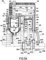
- the figure 5A illustrates the internal structure of the actuator module 100.
- the motor piston 110 is housed in the sleeve 111 which forms an enclosure delimiting a working chamber 113 whose volume, between the end 110a of the motor piston 110 and the plate 130, is variable depending on the position of the motor piston 110.
- the displacement piston 150 is movable in an enclosure 155 delimited by the sleeve 151, the displacement piston separating in this enclosure a low temperature chamber 1150 and a high temperature chamber 1151.
- the two chambers 1150 and 1151 have a variable volume depending on the position of the displacement piston.
- the bottom of the element 1510 of the jacket 151 comprises an opening 1512 opening into the bottom 161 of the cylindrical housing 160, the bottom 161 comprising openings 1610 cooperating with the inlet 6212 of the housing 6210 of the heating device 620 which receives a solar radiation Rs.
- the cylindrical casing 160 further comprises an opening 164 cooperating with the outlet 6213 of the housing 6210 of the solar heating device 620.
- the actuation module 100 comprises a closed fluid circulation circuit 180 formed between the housing 6210 and the working chamber 113, this circuit being formed by a circular gap 165 corresponding to a clearance between the element 1510 of the sleeve 151 and the casing 160, a cylindrical enclosure 162 also included between the element 1510 of the jacket 151 and the casing 160, the cooling device 1230, the low-temperature chamber 1550, a recess 133 made in the plate 130 and the high-temperature chamber 1551.
- the internal volume of the actuator module consisting of the housing 6210, the working chamber 113 and the fluid circulation circuit 180, is filled with a gaseous fluid which expands when its temperature is raised, that is to say - say a fluid having a high coefficient of thermal expansion.
- Such a fluid can in particular be chosen from the following fluids: air, hydrogen, freon and helium. Any other fluid having the ability to expand sufficiently to drive each actuator module can be used in the motor of the invention.
- Each actuation module comprises at least one valve making it possible to drain and fill each circulation circuit with the desired fluid (not shown in the figures).
- the motor piston 110 and the displacement piston 150 are arranged adjacent in the same plane parallel to the axis of the central shaft in particular thanks to the use of the rocker 153 placed above the motor piston 110 which makes it possible to arrange the control rod 152 and the rocker rod 154 as close as possible to the engine piston and in the same plane as the latter. Thanks to this arrangement, it is possible to minimize the size of each actuator module and improve the compactness of the motor.
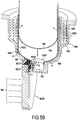
- the figures 5A and 5B represent the actuation module 100, when the fluid F circulates from the outlet 6213 of the housing 6210 in which it is heated to the working chamber 113. More precisely, under the effect of its expansion and / or of the movement of the displacement piston 150 downwards, the fluid F first circulates as it exits the housing 6210 in a circular gap 165 corresponding to a clearance between the element 1510 of the sleeve 151 and the housing 160 ( figure 5B ). The fluid F then arrives in the cylindrical enclosure 162.
- the cylindrical enclosure 162 contains a gas regenerator 163 corresponding to a material having a good heat capacity such as copper wires 1630 for example.
- the regenerator 163 a significant part of the thermal energy of the fluid F is captured by the regenerator 163.
- the cooled fluid F then circulates through the grooves. 1232 located between the fins 1231 of the cooling device 1230 surrounding the housing 123 of the cylinder block 120 so as to open out at an annular gap 1233 formed between the top of the cooling device 1230 and the plate 130, the annular gap 1233 communicating both with the low temperature chamber 1550 and the recess 133 and extending between the low temperature chamber 1150 and the working chamber 113.
- the fluid F can thus reach the working chamber 113 by passing through the recess 133.
- the fluid F circulates from the working chamber 113 to the housing 6210, passing respectively through the recess 133, the cooling device 1230, the regenerator 163, the circular gap 165 and the outlet 6213 of the housing 6210.
- the displacement piston 150 rises, part of the fluid F present in the low temperature chamber is brought into the 6210 box by the same path.
- the motor piston 110 is connected to the crank pin 6110 secured to the shaft 610 by its connecting rod 112 while the displacement piston is connected to the cam 6120 also secured to the shaft 610 by the control rod 152, the rocker 153 and rocker rod 154.
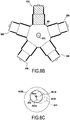
- the crank pin 6110 rotates around its axis A 6110 while the cam 6120 rotates around its axis A 6120 , the axes A 6110 and A 6120 being in eccentric positions with respect to the axis A 610 of the shaft 610.
- the axes A 6110 and A 6120 are placed relative to the axis A 610 at respective positions forming an angle of 90 ° with the axis A 610 .
- the axes A 6110 and A 6120 thus rotate around the axis A 610 with an angular phase shift of 90 ° so that the movement of the motor piston 110 has a phase delay of 90 ° on the movement of the displacement piston 150.
- the structure and operation of the actuator modules 200, 300, 400 and 500 are identical to those which have just been described for the actuator module 100 and will not be described again for the sake of simplicity.
- the actuator modules 200, 300, 400 and 500 differ from the actuator module 100 simply in that the connecting rods 212, 312, 412 and 512 of the engine pistons 210, 310, 410 and 510 as well as the rocker rods 254, 354, 454 and 554 of the displacement pistons 250, 350, 450 and 550 are respectively connecting rods and follower control rods while the connecting rod 112 and the control rod 154 of the actuator module 100 are respectively a connecting rod and a master control rod.
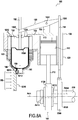
- the displacement piston 150 is in its maximum high position just before starting a downward movement so that the majority of the gas is present under the displacement piston, that is to say in the high temperature chamber 1551 which is in communication with the input 6212 of the housing 6210.
- this phase of rotation which corresponds to the isochoric heating phase of the thermodynamic cycle in the actuator module, the temperature and the pressure of the fluid present in the module of actuation 100 increase while the volume thereof is relatively constant.
- the isochoric heating phase is followed by the isothermal expansion phase.
- the fluid present in particular in the housing 6210 then expands under the effect of the heat received and leaves the latter through the outlet 6213.
- the gas passes through the regenerator 163 where it gives up a very large part of its heat.
- the fluid continues to travel through the cooling device 1230 and arrives in the working chamber 113.
- the pressure of the fluid decreases while its volume increases, in particular in the working chamber 113, which causes a pushing force on the piston.
- motor 110 which initiates a downward movement at the same time as the displacement piston.
- the connecting rod 112 of the engine piston 110 then exerts a pushing force on the crank pin 6110 via its head 1120. This push contributes to the rotation of the engine 600.
- the displacement piston 150 is in an intermediate position where the fluid is both present in the low temperature chamber 1550 and in the high temperature chamber 1551.
- the temperature of the fluid is relatively constant while its pressure decreases.
- the motor piston 110 also continues its downward movement.
- the isothermal expansion phase is then followed by the isochoric cooling phase of the fluid in the actuation module which corresponds to a drop in the pressure and temperature of the fluid.
- the displacement piston 150 is in its maximum lower position. The majority of the gas has passed through the regenerator 163 and is in the low temperature chamber 1550 and in the working chamber 113. The motor piston 110 is then in an upward movement. At this point, the temperature and pressure of the gas in the actuator module 100 are at a minimum.
- the isochoric cooling phase is followed by the isothermal compression phase in which the pressure of the fluid increases while its volume decreases.
- the motor piston 110 is in its maximum high position while the displacement piston 150 is in upward movement, which causes a movement of the fluid located in the low temperature chamber 1550 through the cooling device 1230 and especially the regenerator 163 which will restore the heat captured before to the gas.
- the gas continues to move towards the 6210 housing and the high temperature chamber.
- the motor 600 and the actuator module are found in the configuration of the figures 7A , 7B and 7C already described above.
- the engine according to the invention is very low polluting because it does not use internal or external combustion means for its drive and therefore does not reject combustion gas.
- the engine of the invention also requires little maintenance and operates very quietly.
- each actuation module and, consequently, the motor have a compact structure in particular thanks to the presence of a fluid circulation circuit connecting the solar heating device to the working chamber of the motor piston.
- each actuation module the operation of which is based on the principle of the Stirling engine, is in permanent rotation around the central shaft, which makes it possible to create natural ventilation, in particularly on the outer wall of the working chamber of the engine piston, and consequently accelerate the cooling of the fluid at the end of the thermodynamic cycle. This improves the efficiency of the engine.
- the figure 10 shows a system 900 composed of a support device 700 on which is mounted the fluid expansion motor 600 already described in detail previously.
- the support device 700 comprises a frame 710 comprising a base 711 intended to be placed or fixed to the ground or to a support and a mast 712 connected to the base 711.
- the mast 712 comprises a first bearing 7120 supporting the free end of the 'central shaft 610 of the motor 600 and a second bearing 7121 supporting an energy recovery shaft 750.
- the shaft 750 is driven in rotation by the motor 600 by means of a belt 750 connecting a wheel 720 mounted on the shaft 610 of the motor 600 to a wheel 740 mounted on the shaft 750.
- the energy thus recovered by the shaft 750 in the form of a rotational movement can be used directly in the form of mechanical energy by connecting to the shaft 740 a mechanical device (not shown on the figure 10 ), for example a pumping system, or in the form of electrical energy by connecting to the shaft 740 an alternator (not shown in figure 10 ) and possibly batteries for the storage of electrical energy.
- a mechanical device not shown on the figure 10
- an alternator not shown in figure 10
- Any other electrical or thermal energy generation system can of course be associated with the 900 system.
- the system 900 is used with a parabolic mirror 900 which makes it possible to concentrate the solar radiation Rs on the housings of the solar heating device 620 of the motor 600.
- the mirror 900 is positioned and movable relative to the motor 600 so that its focus corresponds to the position of the solar heater 620.
Landscapes
- Engineering & Computer Science (AREA)
- Mechanical Engineering (AREA)
- General Engineering & Computer Science (AREA)
- Chemical & Material Sciences (AREA)
- Combustion & Propulsion (AREA)
- Life Sciences & Earth Sciences (AREA)
- Sustainable Development (AREA)
- Sustainable Energy (AREA)
- Engine Equipment That Uses Special Cycles (AREA)
Claims (8)
- Heißfluid-Expansionsmotor (600), umfassend eine mittlere Welle (610) und eine Vielzahl von Betätigungsmodulen (100, 200, 300, 400, 500), die um die mittlere Welle (610) herum sternförmig angeordnet sind, wobei jedes Modul (100; 200; 300; 400; 500) umfasst:- einen Antriebskolben (110; 210; 310; 410; 510), der in einem ersten Raum (111) beweglich ist, wobei der Antriebskolben (110) in dem ersten Raum eine Arbeitskammer mit variablem Volumen (113) begrenzt,- einen Bewegungskolben (150; 250; 350; 450; 550), der in einem zweiten Raum (155) beweglich ist, wobei der Bewegungskolben (150) in dem zweiten Raum eine Niedertemperaturkammer mit variablem Volumen (1550) von einer Hochtemperaturkammer mit variablem Volumen (1551) trennt, wobei die Niedertemperaturkammer (1550) mit der Arbeitskammer (113) in Verbindung steht,Motor, bei dem der Antriebskolben (110) und der Bewegungskolben (150) eines jeden Betätigungsmoduls (100) mit der mittleren Welle (610) durch eine erste bzw. eine zweite exzentrische Übertragungsvorrichtung (1120, 112; 1540, 154, 153, 152) verbunden sind, welche geeignet sind, jeden Kolben verschieblich hin und her zu bewegen, wobei die Bewegung des Antriebskolbens eine Phasenverzögerung von 90° gegenüber der Bewegung des Bewegungskolbens aufweist, wobei jedes Modul (100; 200; 300; 400; 500) um die mittlere Welle (610) drehend angetrieben wird, um die Abkühlung des Fluids in der Arbeitskammer zu beschleunigen,
Motor, bei dem jedes Betätigungsmodul (100; 200; 300; 400; 500), der Antriebskolben (110; 210; 310; 410; 510) und der Bewegungskolben (150; 250; 350; 450; 550) in einer gleichen Ebene senkrecht zur Achse der mittleren Welle (610) benachbart angeordnet sind,
dadurch gekennzeichnet, dass er ferner eine Fluidheizvorrichtung (620) umfasst, wobei jede Hochtemperaturkammer (1551) mit der Fluidheizvorrichtung (620) in Verbindung steht und jede Arbeitskammer (113) durch einen Fluidzirkulationskreis (180) mit der Fluidheizvorrichtung verbunden ist, und dass der Fluidzirkulationskreis (180) eines jeden Betätigungsmoduls (100) einen Gasregenerator (163) umfasst, der sich um die Hochtemperaturkammer (1551) herum erstreckt, und dass jeder Bewegungskolben (150; 250; 350; 450; 550) über eine Führungsstange (152; 252; 352; 452; 552) mit einem ersten Ende einer Kippvorrichtung (153; 253; 353; 453; 553) verbunden ist, wobei das zweite Ende der Kippvorrichtung mit einem Ende einer Steuerstange (154; 254; 354; 454; 554) verbunden ist, wobei das gegenüberliegende Ende der Steuerstange mit einem Nockenfolger (1540) verbunden ist, der an einem Nocken (6120) angebracht ist, welcher mit der mittleren Welle (610) fest verbunden ist. - Motor nach Anspruch 1, dadurch gekennzeichnet, dass jedes Betätigungsmodul (100; 200; 300; 400; 500) einen Zylinderblock (120; 220; 320; 420; 520) umfasst, der eine innere Aufnahme (121; 221; 321; 421; 521) aufweist, welche der Arbeitskammer entspricht, wobei der Zylinderblock Kühlrippen (122; 222; 322; 422; 522) an seiner Außenfläche aufweist.
- Motor nach Anspruch 1 oder 2, dadurch gekennzeichnet, dass der Fluidzirkulationskreis (180) eines jeden Betätigungsmoduls (100) einen Kühlkörper (1230) aufweist, der sich um die Niedertemperaturkammer (1550) herum erstreckt.
- Motor nach einem der Ansprüche 1 bis 3, dadurch gekennzeichnet, dass die Fluidheizvorrichtung (620) eine Vielzahl von Sammelgehäusen (6210; 6220; 6230; 6240; 6250) umfasst, die jeweils ein Netz aus Kanälen (6211; 6221; 6231; 6241; 6251) enthalten, das sich zwischen einem Einlass (6212; 6222; 6232; 6242; 6252) und einem Auslass (6213; 6223; 6233; 6243; 6253) erstreckt, wobei der Einlass (6212; 6222; 6232; 6242; 6252) eines jeden Gehäuses (6210; 6220; 6230; 6240; 6250) mit der Hochtemperaturkammer (1551) eines entsprechenden Betätigungsmoduls (100; 200; 300; 400; 500) verbunden ist, und wobei der Auslass (6213; 6223; 6233; 6243; 6253) des Gehäuses mit dem Fluidzirkulationskreis (180) des entsprechenden Betätigungsmoduls (100) verbunden ist.
- Motor nach einem der Ansprüche 1 bis 4, dadurch gekennzeichnet, dass er eine Vorrichtung zum Konzentrieren der Sonnenstrahlung (900) umfasst, die geeignet ist, Sonnenstrahlen (Rs) auf die Sammelgehäuse (6210; 6220; 6230; 6240; 6250) der Fluidheizvorrichtung (120) zu konzentrieren.
- Motor nach einem der Ansprüche 1 bis 4, dadurch gekennzeichnet, dass er Heizmittel umfasst, die geeignet sind, Wärme an die Sammelgehäuse (6210; 6220; 6230; 6240; 6250) der Fluidheizvorrichtung (620) zu übertragen.
- Motor nach einem der Ansprüche 1 bis 6, dadurch gekennzeichnet, dass jeder Antriebskolben (110; 210; 310; 410; 510) mit einem Ende einer Pleuelstange (112; 212; 312; 412; 512) verbunden ist, wobei das gegenüberliegende Ende der Pleuelstange mit einem Kopf (1120) verbunden ist, der an einem Zapfen (6110) einer Kurbelwelle (611), welche an der mittleren Welle (610) vorhanden ist, angebracht ist.
- Motor nach einem der Ansprüche 1 bis 7, dadurch gekennzeichnet, dass jedes Betätigungsmodul (100; 200; 300; 400; 500) ein gasförmiges Fluid enthält, das aus wenigstens einem der folgenden gasförmigen Fluide ausgewählt ist: Luft, Wasserstoff, Freon und Helium.
Priority Applications (3)
| Application Number | Priority Date | Filing Date | Title |
|---|---|---|---|
| ES13169300T ES2827320T3 (es) | 2013-05-27 | 2013-05-27 | Motor de expansión de fluido |
| EP13169300.4A EP2808528B1 (de) | 2013-05-27 | 2013-05-27 | Motor mit Flüssigkeitsausdehnung |
| US14/287,313 US9598959B2 (en) | 2013-05-27 | 2014-05-27 | Fluid expansion engine |
Applications Claiming Priority (1)
| Application Number | Priority Date | Filing Date | Title |
|---|---|---|---|
| EP13169300.4A EP2808528B1 (de) | 2013-05-27 | 2013-05-27 | Motor mit Flüssigkeitsausdehnung |
Publications (2)
| Publication Number | Publication Date |
|---|---|
| EP2808528A1 EP2808528A1 (de) | 2014-12-03 |
| EP2808528B1 true EP2808528B1 (de) | 2020-08-05 |
Family
ID=48534200
Family Applications (1)
| Application Number | Title | Priority Date | Filing Date |
|---|---|---|---|
| EP13169300.4A Not-in-force EP2808528B1 (de) | 2013-05-27 | 2013-05-27 | Motor mit Flüssigkeitsausdehnung |
Country Status (3)
| Country | Link |
|---|---|
| US (1) | US9598959B2 (de) |
| EP (1) | EP2808528B1 (de) |
| ES (1) | ES2827320T3 (de) |
Families Citing this family (2)
| Publication number | Priority date | Publication date | Assignee | Title |
|---|---|---|---|---|
| JP2019052563A (ja) * | 2017-09-13 | 2019-04-04 | 和広 千野 | スターリングエンジン及びスターリング冷凍機 |
| DE102019131363B3 (de) * | 2019-11-20 | 2020-10-01 | Friedrich Baum | Heißluftmotor mit einer umlaufenden Zylinderanordnung um eine feststehende Kurbelwelle |
Citations (1)
| Publication number | Priority date | Publication date | Assignee | Title |
|---|---|---|---|---|
| US20020124561A1 (en) * | 2001-03-12 | 2002-09-12 | Masaki Ban | Stirling engine |
Family Cites Families (20)
| Publication number | Priority date | Publication date | Assignee | Title |
|---|---|---|---|---|
| US1316346A (en) * | 1919-09-16 | augustine | ||
| BE523269A (de) * | ||||
| US751694A (en) * | 1904-02-09 | sheaeee | ||
| US1382611A (en) * | 1917-08-15 | 1921-06-28 | Benjamin F Augustine | Rotary gas-engine |
| US1300916A (en) * | 1917-11-07 | 1919-04-15 | Bernard M Beach | Internal-combustion engine. |
| CH442865A (de) * | 1966-02-23 | 1967-08-31 | Wyssbrod Hans | Kolbenmotor mit umlaufenden Zylindern |
| US3657877A (en) * | 1971-02-01 | 1972-04-25 | Thermo Electron Corp | Tidal regenerator heat engine |
| US3857371A (en) * | 1973-06-04 | 1974-12-31 | T Gibson | Rotary internal combustion engine |
| US4642988A (en) * | 1981-08-14 | 1987-02-17 | New Process Industries, Inc. | Solar powered free-piston Stirling engine |
| US4677825A (en) * | 1986-06-12 | 1987-07-07 | Fellows Oscar L | Thermomotor |
| US5177968A (en) * | 1992-05-20 | 1993-01-12 | Fellows Oscar L | Radial hot gas engine |
| US5303679A (en) * | 1993-08-12 | 1994-04-19 | Vicente Gamon | Rotary internal combustion engine |
| DE4336975A1 (de) * | 1993-10-29 | 1995-05-04 | Erno Raumfahrttechnik Gmbh | Energieerzeugungseinrichtung |
| US5390496A (en) * | 1994-03-04 | 1995-02-21 | El Affaqui; Thami | Stirling engine with annular cam |
| US5884481A (en) * | 1997-07-14 | 1999-03-23 | Stm Corporation | Heat engine heater assembly |
| US20030226525A1 (en) * | 2002-06-11 | 2003-12-11 | Warren Edward Lawrence | Warren cycle internal combustion engine with heat exchanger |
| US6979911B2 (en) * | 2003-05-08 | 2005-12-27 | United Technologies Corporation | Method and apparatus for solar power conversion |
| DE102004059928B4 (de) * | 2004-12-13 | 2007-12-13 | Robert Welle | Stirlingsternmotor |
| DE102009023024A1 (de) * | 2009-05-28 | 2010-12-09 | Schliebe, Günther | Stirlingmotoranordnung |
| EP2434135A1 (de) * | 2010-09-24 | 2012-03-28 | Neemat Frem | Expansions-Rotationsmotor |
-
2013
- 2013-05-27 EP EP13169300.4A patent/EP2808528B1/de not_active Not-in-force
- 2013-05-27 ES ES13169300T patent/ES2827320T3/es active Active
-
2014
- 2014-05-27 US US14/287,313 patent/US9598959B2/en active Active
Patent Citations (1)
| Publication number | Priority date | Publication date | Assignee | Title |
|---|---|---|---|---|
| US20020124561A1 (en) * | 2001-03-12 | 2002-09-12 | Masaki Ban | Stirling engine |
Also Published As
| Publication number | Publication date |
|---|---|
| US9598959B2 (en) | 2017-03-21 |
| EP2808528A1 (de) | 2014-12-03 |
| ES2827320T3 (es) | 2021-05-20 |
| US20140345269A1 (en) | 2014-11-27 |
Similar Documents
| Publication | Publication Date | Title |
|---|---|---|
| EP2031234B1 (de) | Erzeugung elektrischer Energie in einem Turbotriebwerk mittels eines Stirlingmotors | |
| CA2751395C (fr) | Generation thermoelectrique pour turbine a gaz | |
| EP2556236B1 (de) | Stirlingmaschine | |
| US9086013B2 (en) | Gerotor rotary Stirling cycle engine | |
| EP2434135A1 (de) | Expansions-Rotationsmotor | |
| US6647725B1 (en) | Thermal differential engine apparatus | |
| BE897859A (fr) | Moteur rotatif | |
| FR2681906A1 (fr) | Pompe centrifuge pour circuit de liquide de refroidissement de moteur a combustion. | |
| EP2808528A1 (de) | Motor mit Flüssigkeitsausdehnung | |
| WO2014080130A1 (fr) | Groupe de conversion d'une energie thermique en une energie hydraulique | |
| EP3099919B1 (de) | Externer verbrennungsmotor | |
| EP4222365B1 (de) | Stirling-kreislaufmaschine | |
| WO2013188932A2 (fr) | Système de distribution directe pour moteur a combustion interne | |
| FR3025254B1 (fr) | Moteur a pressions d'evaporation differentielles | |
| FR2817592A1 (fr) | Moteur a pistons gigognes croises a sources thermiques externes | |
| FR2972481A1 (fr) | Machine thermique a cylindree variable | |
| FR3140653A1 (fr) | Dispositif pour la conversion d’energie | |
| FR2957137A1 (fr) | Module a echangeurs thermiques pour moteur stirling et moteur strirling comportant au moins un tel module | |
| FR2950391A1 (fr) | Moteur thermique a explosion | |
| FR2998007A1 (fr) | Piston a soupape integree | |
| FR3081032A3 (fr) | Moteur a chaleur externe | |
| WO2011128520A1 (fr) | Moteur thermique sans carburant adaptable notamment a l'automobile et au nucleaire | |
| FR3031770A1 (fr) | Moteur thermique a condensation | |
| FR2950935A1 (fr) | Moteur de type stirling | |
| WO1982000497A1 (en) | Heat engine |
Legal Events
| Date | Code | Title | Description |
|---|---|---|---|
| PUAI | Public reference made under article 153(3) epc to a published international application that has entered the european phase |
Free format text: ORIGINAL CODE: 0009012 |
|
| 17P | Request for examination filed |
Effective date: 20130527 |
|
| AK | Designated contracting states |
Kind code of ref document: A1 Designated state(s): AL AT BE BG CH CY CZ DE DK EE ES FI FR GB GR HR HU IE IS IT LI LT LU LV MC MK MT NL NO PL PT RO RS SE SI SK SM TR |
|
| AX | Request for extension of the european patent |
Extension state: BA ME |
|
| R17P | Request for examination filed (corrected) |
Effective date: 20150529 |
|
| RBV | Designated contracting states (corrected) |
Designated state(s): AL AT BE BG CH CY CZ DE DK EE ES FI FR GB GR HR HU IE IS IT LI LT LU LV MC MK MT NL NO PL PT RO RS SE SI SK SM TR |
|
| STAA | Information on the status of an ep patent application or granted ep patent |
Free format text: STATUS: EXAMINATION IS IN PROGRESS |
|
| 17Q | First examination report despatched |
Effective date: 20180111 |
|
| REG | Reference to a national code |
Ref country code: DE Ref legal event code: R079 Ref document number: 602013071258 Country of ref document: DE Free format text: PREVIOUS MAIN CLASS: F02G0001044000 Ipc: F01B0009060000 |
|
| GRAP | Despatch of communication of intention to grant a patent |
Free format text: ORIGINAL CODE: EPIDOSNIGR1 |
|
| STAA | Information on the status of an ep patent application or granted ep patent |
Free format text: STATUS: GRANT OF PATENT IS INTENDED |
|
| RIC1 | Information provided on ipc code assigned before grant |
Ipc: F03G 6/04 20060101ALI20200214BHEP Ipc: F01B 1/06 20060101ALI20200214BHEP Ipc: F02G 1/044 20060101ALI20200214BHEP Ipc: F02G 1/055 20060101ALI20200214BHEP Ipc: F01B 9/06 20060101AFI20200214BHEP Ipc: F01B 9/02 20060101ALI20200214BHEP Ipc: F03G 6/06 20060101ALI20200214BHEP |
|
| INTG | Intention to grant announced |
Effective date: 20200303 |
|
| GRAS | Grant fee paid |
Free format text: ORIGINAL CODE: EPIDOSNIGR3 |
|
| GRAA | (expected) grant |
Free format text: ORIGINAL CODE: 0009210 |
|
| STAA | Information on the status of an ep patent application or granted ep patent |
Free format text: STATUS: THE PATENT HAS BEEN GRANTED |
|
| AK | Designated contracting states |
Kind code of ref document: B1 Designated state(s): AL AT BE BG CH CY CZ DE DK EE ES FI FR GB GR HR HU IE IS IT LI LT LU LV MC MK MT NL NO PL PT RO RS SE SI SK SM TR |
|
| REG | Reference to a national code |
Ref country code: GB Ref legal event code: FG4D Free format text: NOT ENGLISH |
|
| REG | Reference to a national code |
Ref country code: CH Ref legal event code: EP |
|
| REG | Reference to a national code |
Ref country code: AT Ref legal event code: REF Ref document number: 1298949 Country of ref document: AT Kind code of ref document: T Effective date: 20200815 |
|
| REG | Reference to a national code |
Ref country code: DE Ref legal event code: R096 Ref document number: 602013071258 Country of ref document: DE |
|
| REG | Reference to a national code |
Ref country code: IE Ref legal event code: FG4D Free format text: LANGUAGE OF EP DOCUMENT: FRENCH |
|
| REG | Reference to a national code |
Ref country code: CH Ref legal event code: NV Representative=s name: MICHELI AND CIE SA, CH |
|
| REG | Reference to a national code |
Ref country code: GR Ref legal event code: EP Ref document number: 20200402927 Country of ref document: GR Effective date: 20201116 |
|
| REG | Reference to a national code |
Ref country code: LT Ref legal event code: MG4D |
|
| REG | Reference to a national code |
Ref country code: NL Ref legal event code: MP Effective date: 20200805 |
|
| REG | Reference to a national code |
Ref country code: AT Ref legal event code: MK05 Ref document number: 1298949 Country of ref document: AT Kind code of ref document: T Effective date: 20200805 |
|
| PG25 | Lapsed in a contracting state [announced via postgrant information from national office to epo] |
Ref country code: LT Free format text: LAPSE BECAUSE OF FAILURE TO SUBMIT A TRANSLATION OF THE DESCRIPTION OR TO PAY THE FEE WITHIN THE PRESCRIBED TIME-LIMIT Effective date: 20200805 Ref country code: FI Free format text: LAPSE BECAUSE OF FAILURE TO SUBMIT A TRANSLATION OF THE DESCRIPTION OR TO PAY THE FEE WITHIN THE PRESCRIBED TIME-LIMIT Effective date: 20200805 Ref country code: SE Free format text: LAPSE BECAUSE OF FAILURE TO SUBMIT A TRANSLATION OF THE DESCRIPTION OR TO PAY THE FEE WITHIN THE PRESCRIBED TIME-LIMIT Effective date: 20200805 Ref country code: HR Free format text: LAPSE BECAUSE OF FAILURE TO SUBMIT A TRANSLATION OF THE DESCRIPTION OR TO PAY THE FEE WITHIN THE PRESCRIBED TIME-LIMIT Effective date: 20200805 Ref country code: PT Free format text: LAPSE BECAUSE OF FAILURE TO SUBMIT A TRANSLATION OF THE DESCRIPTION OR TO PAY THE FEE WITHIN THE PRESCRIBED TIME-LIMIT Effective date: 20201207 Ref country code: BG Free format text: LAPSE BECAUSE OF FAILURE TO SUBMIT A TRANSLATION OF THE DESCRIPTION OR TO PAY THE FEE WITHIN THE PRESCRIBED TIME-LIMIT Effective date: 20201105 Ref country code: NO Free format text: LAPSE BECAUSE OF FAILURE TO SUBMIT A TRANSLATION OF THE DESCRIPTION OR TO PAY THE FEE WITHIN THE PRESCRIBED TIME-LIMIT Effective date: 20201105 Ref country code: AT Free format text: LAPSE BECAUSE OF FAILURE TO SUBMIT A TRANSLATION OF THE DESCRIPTION OR TO PAY THE FEE WITHIN THE PRESCRIBED TIME-LIMIT Effective date: 20200805 |
|
| PG25 | Lapsed in a contracting state [announced via postgrant information from national office to epo] |
Ref country code: PL Free format text: LAPSE BECAUSE OF FAILURE TO SUBMIT A TRANSLATION OF THE DESCRIPTION OR TO PAY THE FEE WITHIN THE PRESCRIBED TIME-LIMIT Effective date: 20200805 Ref country code: RS Free format text: LAPSE BECAUSE OF FAILURE TO SUBMIT A TRANSLATION OF THE DESCRIPTION OR TO PAY THE FEE WITHIN THE PRESCRIBED TIME-LIMIT Effective date: 20200805 Ref country code: NL Free format text: LAPSE BECAUSE OF FAILURE TO SUBMIT A TRANSLATION OF THE DESCRIPTION OR TO PAY THE FEE WITHIN THE PRESCRIBED TIME-LIMIT Effective date: 20200805 Ref country code: LV Free format text: LAPSE BECAUSE OF FAILURE TO SUBMIT A TRANSLATION OF THE DESCRIPTION OR TO PAY THE FEE WITHIN THE PRESCRIBED TIME-LIMIT Effective date: 20200805 Ref country code: IS Free format text: LAPSE BECAUSE OF FAILURE TO SUBMIT A TRANSLATION OF THE DESCRIPTION OR TO PAY THE FEE WITHIN THE PRESCRIBED TIME-LIMIT Effective date: 20201205 |
|
| PG25 | Lapsed in a contracting state [announced via postgrant information from national office to epo] |
Ref country code: CZ Free format text: LAPSE BECAUSE OF FAILURE TO SUBMIT A TRANSLATION OF THE DESCRIPTION OR TO PAY THE FEE WITHIN THE PRESCRIBED TIME-LIMIT Effective date: 20200805 Ref country code: DK Free format text: LAPSE BECAUSE OF FAILURE TO SUBMIT A TRANSLATION OF THE DESCRIPTION OR TO PAY THE FEE WITHIN THE PRESCRIBED TIME-LIMIT Effective date: 20200805 Ref country code: EE Free format text: LAPSE BECAUSE OF FAILURE TO SUBMIT A TRANSLATION OF THE DESCRIPTION OR TO PAY THE FEE WITHIN THE PRESCRIBED TIME-LIMIT Effective date: 20200805 Ref country code: SM Free format text: LAPSE BECAUSE OF FAILURE TO SUBMIT A TRANSLATION OF THE DESCRIPTION OR TO PAY THE FEE WITHIN THE PRESCRIBED TIME-LIMIT Effective date: 20200805 Ref country code: RO Free format text: LAPSE BECAUSE OF FAILURE TO SUBMIT A TRANSLATION OF THE DESCRIPTION OR TO PAY THE FEE WITHIN THE PRESCRIBED TIME-LIMIT Effective date: 20200805 |
|
| REG | Reference to a national code |
Ref country code: DE Ref legal event code: R097 Ref document number: 602013071258 Country of ref document: DE |
|
| REG | Reference to a national code |
Ref country code: ES Ref legal event code: FG2A Ref document number: 2827320 Country of ref document: ES Kind code of ref document: T3 Effective date: 20210520 |
|
| PG25 | Lapsed in a contracting state [announced via postgrant information from national office to epo] |
Ref country code: AL Free format text: LAPSE BECAUSE OF FAILURE TO SUBMIT A TRANSLATION OF THE DESCRIPTION OR TO PAY THE FEE WITHIN THE PRESCRIBED TIME-LIMIT Effective date: 20200805 |
|
| PLBE | No opposition filed within time limit |
Free format text: ORIGINAL CODE: 0009261 |
|
| STAA | Information on the status of an ep patent application or granted ep patent |
Free format text: STATUS: NO OPPOSITION FILED WITHIN TIME LIMIT |
|
| PG25 | Lapsed in a contracting state [announced via postgrant information from national office to epo] |
Ref country code: SK Free format text: LAPSE BECAUSE OF FAILURE TO SUBMIT A TRANSLATION OF THE DESCRIPTION OR TO PAY THE FEE WITHIN THE PRESCRIBED TIME-LIMIT Effective date: 20200805 |
|
| 26N | No opposition filed |
Effective date: 20210507 |
|
| PG25 | Lapsed in a contracting state [announced via postgrant information from national office to epo] |
Ref country code: SI Free format text: LAPSE BECAUSE OF FAILURE TO SUBMIT A TRANSLATION OF THE DESCRIPTION OR TO PAY THE FEE WITHIN THE PRESCRIBED TIME-LIMIT Effective date: 20200805 |
|
| PG25 | Lapsed in a contracting state [announced via postgrant information from national office to epo] |
Ref country code: LU Free format text: LAPSE BECAUSE OF NON-PAYMENT OF DUE FEES Effective date: 20210527 Ref country code: MC Free format text: LAPSE BECAUSE OF FAILURE TO SUBMIT A TRANSLATION OF THE DESCRIPTION OR TO PAY THE FEE WITHIN THE PRESCRIBED TIME-LIMIT Effective date: 20200805 |
|
| PG25 | Lapsed in a contracting state [announced via postgrant information from national office to epo] |
Ref country code: IE Free format text: LAPSE BECAUSE OF NON-PAYMENT OF DUE FEES Effective date: 20210527 |
|
| PGFP | Annual fee paid to national office [announced via postgrant information from national office to epo] |
Ref country code: IT Payment date: 20220510 Year of fee payment: 10 Ref country code: GB Payment date: 20220519 Year of fee payment: 10 Ref country code: FR Payment date: 20220420 Year of fee payment: 10 Ref country code: ES Payment date: 20220602 Year of fee payment: 10 Ref country code: DE Payment date: 20220511 Year of fee payment: 10 |
|
| PGFP | Annual fee paid to national office [announced via postgrant information from national office to epo] |
Ref country code: GR Payment date: 20220518 Year of fee payment: 10 Ref country code: CH Payment date: 20220530 Year of fee payment: 10 Ref country code: BE Payment date: 20220520 Year of fee payment: 10 |
|
| REG | Reference to a national code |
Ref country code: DE Ref legal event code: R082 Ref document number: 602013071258 Country of ref document: DE Representative=s name: CBDL PATENTANWAELTE GBR, DE |
|
| PG25 | Lapsed in a contracting state [announced via postgrant information from national office to epo] |
Ref country code: HU Free format text: LAPSE BECAUSE OF FAILURE TO SUBMIT A TRANSLATION OF THE DESCRIPTION OR TO PAY THE FEE WITHIN THE PRESCRIBED TIME-LIMIT; INVALID AB INITIO Effective date: 20130527 |
|
| PG25 | Lapsed in a contracting state [announced via postgrant information from national office to epo] |
Ref country code: CY Free format text: LAPSE BECAUSE OF FAILURE TO SUBMIT A TRANSLATION OF THE DESCRIPTION OR TO PAY THE FEE WITHIN THE PRESCRIBED TIME-LIMIT Effective date: 20200805 |
|
| REG | Reference to a national code |
Ref country code: DE Ref legal event code: R119 Ref document number: 602013071258 Country of ref document: DE |
|
| REG | Reference to a national code |
Ref country code: CH Ref legal event code: PL |
|
| PG25 | Lapsed in a contracting state [announced via postgrant information from national office to epo] |
Ref country code: GR Free format text: LAPSE BECAUSE OF NON-PAYMENT OF DUE FEES Effective date: 20231208 |
|
| GBPC | Gb: european patent ceased through non-payment of renewal fee |
Effective date: 20230527 |
|
| REG | Reference to a national code |
Ref country code: BE Ref legal event code: MM Effective date: 20230531 |
|
| PG25 | Lapsed in a contracting state [announced via postgrant information from national office to epo] |
Ref country code: LI Free format text: LAPSE BECAUSE OF NON-PAYMENT OF DUE FEES Effective date: 20230531 Ref country code: GR Free format text: LAPSE BECAUSE OF NON-PAYMENT OF DUE FEES Effective date: 20231208 Ref country code: CH Free format text: LAPSE BECAUSE OF NON-PAYMENT OF DUE FEES Effective date: 20230531 |
|
| PG25 | Lapsed in a contracting state [announced via postgrant information from national office to epo] |
Ref country code: MK Free format text: LAPSE BECAUSE OF FAILURE TO SUBMIT A TRANSLATION OF THE DESCRIPTION OR TO PAY THE FEE WITHIN THE PRESCRIBED TIME-LIMIT Effective date: 20200805 Ref country code: IT Free format text: LAPSE BECAUSE OF NON-PAYMENT OF DUE FEES Effective date: 20230527 Ref country code: DE Free format text: LAPSE BECAUSE OF NON-PAYMENT OF DUE FEES Effective date: 20231201 Ref country code: GB Free format text: LAPSE BECAUSE OF NON-PAYMENT OF DUE FEES Effective date: 20230527 |
|
| PG25 | Lapsed in a contracting state [announced via postgrant information from national office to epo] |
Ref country code: FR Free format text: LAPSE BECAUSE OF NON-PAYMENT OF DUE FEES Effective date: 20230531 Ref country code: BE Free format text: LAPSE BECAUSE OF NON-PAYMENT OF DUE FEES Effective date: 20230531 |
|
| PG25 | Lapsed in a contracting state [announced via postgrant information from national office to epo] |
Ref country code: TR Free format text: LAPSE BECAUSE OF FAILURE TO SUBMIT A TRANSLATION OF THE DESCRIPTION OR TO PAY THE FEE WITHIN THE PRESCRIBED TIME-LIMIT Effective date: 20200805 |
|
| REG | Reference to a national code |
Ref country code: ES Ref legal event code: FD2A Effective date: 20240704 |
|
| PG25 | Lapsed in a contracting state [announced via postgrant information from national office to epo] |
Ref country code: ES Free format text: LAPSE BECAUSE OF NON-PAYMENT OF DUE FEES Effective date: 20230528 |
|
| PG25 | Lapsed in a contracting state [announced via postgrant information from national office to epo] |
Ref country code: ES Free format text: LAPSE BECAUSE OF NON-PAYMENT OF DUE FEES Effective date: 20230528 |
|
| PG25 | Lapsed in a contracting state [announced via postgrant information from national office to epo] |
Ref country code: MT Free format text: LAPSE BECAUSE OF FAILURE TO SUBMIT A TRANSLATION OF THE DESCRIPTION OR TO PAY THE FEE WITHIN THE PRESCRIBED TIME-LIMIT Effective date: 20200805 |