EP2808515A1 - Control apparatus for internal combustion engine - Google Patents
Control apparatus for internal combustion engine Download PDFInfo
- Publication number
- EP2808515A1 EP2808515A1 EP12866915.7A EP12866915A EP2808515A1 EP 2808515 A1 EP2808515 A1 EP 2808515A1 EP 12866915 A EP12866915 A EP 12866915A EP 2808515 A1 EP2808515 A1 EP 2808515A1
- Authority
- EP
- European Patent Office
- Prior art keywords
- internal combustion
- combustion engine
- oxygen excess
- excess ratio
- opening degree
- Prior art date
- Legal status (The legal status is an assumption and is not a legal conclusion. Google has not performed a legal analysis and makes no representation as to the accuracy of the status listed.)
- Granted
Links
- 238000002485 combustion reaction Methods 0.000 title claims abstract description 71
- QVGXLLKOCUKJST-UHFFFAOYSA-N atomic oxygen Chemical compound [O] QVGXLLKOCUKJST-UHFFFAOYSA-N 0.000 claims abstract description 114
- 239000001301 oxygen Substances 0.000 claims abstract description 114
- 229910052760 oxygen Inorganic materials 0.000 claims abstract description 114
- 230000001052 transient effect Effects 0.000 claims abstract description 80
- 239000007789 gas Substances 0.000 claims abstract description 39
- 230000007246 mechanism Effects 0.000 claims abstract description 27
- 239000000446 fuel Substances 0.000 description 19
- 238000002347 injection Methods 0.000 description 17
- 239000007924 injection Substances 0.000 description 17
- 238000010586 diagram Methods 0.000 description 12
- 230000007423 decrease Effects 0.000 description 10
- 230000003247 decreasing effect Effects 0.000 description 9
- 230000009467 reduction Effects 0.000 description 6
- 230000001276 controlling effect Effects 0.000 description 4
- 238000010276 construction Methods 0.000 description 3
- 230000001133 acceleration Effects 0.000 description 2
- 230000000694 effects Effects 0.000 description 2
- 230000007704 transition Effects 0.000 description 2
- 230000008859 change Effects 0.000 description 1
- 239000000567 combustion gas Substances 0.000 description 1
- 230000006872 improvement Effects 0.000 description 1
- 208000015181 infectious disease Diseases 0.000 description 1
- 239000000463 material Substances 0.000 description 1
- 238000000034 method Methods 0.000 description 1
- 230000001105 regulatory effect Effects 0.000 description 1
- 239000000779 smoke Substances 0.000 description 1
- 239000000243 solution Substances 0.000 description 1
- 238000011144 upstream manufacturing Methods 0.000 description 1
Images


Classifications
-
- F—MECHANICAL ENGINEERING; LIGHTING; HEATING; WEAPONS; BLASTING
- F02—COMBUSTION ENGINES; HOT-GAS OR COMBUSTION-PRODUCT ENGINE PLANTS
- F02D—CONTROLLING COMBUSTION ENGINES
- F02D41/00—Electrical control of supply of combustible mixture or its constituents
- F02D41/0025—Controlling engines characterised by use of non-liquid fuels, pluralities of fuels, or non-fuel substances added to the combustible mixtures
- F02D41/0047—Controlling exhaust gas recirculation [EGR]
- F02D41/005—Controlling exhaust gas recirculation [EGR] according to engine operating conditions
-
- F—MECHANICAL ENGINEERING; LIGHTING; HEATING; WEAPONS; BLASTING
- F02—COMBUSTION ENGINES; HOT-GAS OR COMBUSTION-PRODUCT ENGINE PLANTS
- F02D—CONTROLLING COMBUSTION ENGINES
- F02D21/00—Controlling engines characterised by their being supplied with non-airborne oxygen or other non-fuel gas
- F02D21/06—Controlling engines characterised by their being supplied with non-airborne oxygen or other non-fuel gas peculiar to engines having other non-fuel gas added to combustion air
- F02D21/08—Controlling engines characterised by their being supplied with non-airborne oxygen or other non-fuel gas peculiar to engines having other non-fuel gas added to combustion air the other gas being the exhaust gas of engine
-
- F—MECHANICAL ENGINEERING; LIGHTING; HEATING; WEAPONS; BLASTING
- F02—COMBUSTION ENGINES; HOT-GAS OR COMBUSTION-PRODUCT ENGINE PLANTS
- F02D—CONTROLLING COMBUSTION ENGINES
- F02D23/00—Controlling engines characterised by their being supercharged
-
- F—MECHANICAL ENGINEERING; LIGHTING; HEATING; WEAPONS; BLASTING
- F02—COMBUSTION ENGINES; HOT-GAS OR COMBUSTION-PRODUCT ENGINE PLANTS
- F02D—CONTROLLING COMBUSTION ENGINES
- F02D35/00—Controlling engines, dependent on conditions exterior or interior to engines, not otherwise provided for
- F02D35/02—Controlling engines, dependent on conditions exterior or interior to engines, not otherwise provided for on interior conditions
-
- F—MECHANICAL ENGINEERING; LIGHTING; HEATING; WEAPONS; BLASTING
- F02—COMBUSTION ENGINES; HOT-GAS OR COMBUSTION-PRODUCT ENGINE PLANTS
- F02D—CONTROLLING COMBUSTION ENGINES
- F02D41/00—Electrical control of supply of combustible mixture or its constituents
- F02D41/0002—Controlling intake air
- F02D41/0007—Controlling intake air for control of turbo-charged or super-charged engines
-
- F—MECHANICAL ENGINEERING; LIGHTING; HEATING; WEAPONS; BLASTING
- F02—COMBUSTION ENGINES; HOT-GAS OR COMBUSTION-PRODUCT ENGINE PLANTS
- F02D—CONTROLLING COMBUSTION ENGINES
- F02D41/00—Electrical control of supply of combustible mixture or its constituents
- F02D41/0025—Controlling engines characterised by use of non-liquid fuels, pluralities of fuels, or non-fuel substances added to the combustible mixtures
- F02D41/0047—Controlling exhaust gas recirculation [EGR]
- F02D41/005—Controlling exhaust gas recirculation [EGR] according to engine operating conditions
- F02D41/0052—Feedback control of engine parameters, e.g. for control of air/fuel ratio or intake air amount
-
- F—MECHANICAL ENGINEERING; LIGHTING; HEATING; WEAPONS; BLASTING
- F02—COMBUSTION ENGINES; HOT-GAS OR COMBUSTION-PRODUCT ENGINE PLANTS
- F02D—CONTROLLING COMBUSTION ENGINES
- F02D41/00—Electrical control of supply of combustible mixture or its constituents
- F02D41/02—Circuit arrangements for generating control signals
- F02D41/04—Introducing corrections for particular operating conditions
- F02D41/045—Detection of accelerating or decelerating state
-
- F—MECHANICAL ENGINEERING; LIGHTING; HEATING; WEAPONS; BLASTING
- F02—COMBUSTION ENGINES; HOT-GAS OR COMBUSTION-PRODUCT ENGINE PLANTS
- F02D—CONTROLLING COMBUSTION ENGINES
- F02D41/00—Electrical control of supply of combustible mixture or its constituents
- F02D41/02—Circuit arrangements for generating control signals
- F02D41/04—Introducing corrections for particular operating conditions
- F02D41/10—Introducing corrections for particular operating conditions for acceleration
-
- F—MECHANICAL ENGINEERING; LIGHTING; HEATING; WEAPONS; BLASTING
- F02—COMBUSTION ENGINES; HOT-GAS OR COMBUSTION-PRODUCT ENGINE PLANTS
- F02D—CONTROLLING COMBUSTION ENGINES
- F02D41/00—Electrical control of supply of combustible mixture or its constituents
- F02D41/02—Circuit arrangements for generating control signals
- F02D41/14—Introducing closed-loop corrections
- F02D41/1438—Introducing closed-loop corrections using means for determining characteristics of the combustion gases; Sensors therefor
- F02D41/1444—Introducing closed-loop corrections using means for determining characteristics of the combustion gases; Sensors therefor characterised by the characteristics of the combustion gases
- F02D41/1454—Introducing closed-loop corrections using means for determining characteristics of the combustion gases; Sensors therefor characterised by the characteristics of the combustion gases the characteristics being an oxygen content or concentration or the air-fuel ratio
- F02D41/1458—Introducing closed-loop corrections using means for determining characteristics of the combustion gases; Sensors therefor characterised by the characteristics of the combustion gases the characteristics being an oxygen content or concentration or the air-fuel ratio with determination means using an estimation
-
- F—MECHANICAL ENGINEERING; LIGHTING; HEATING; WEAPONS; BLASTING
- F02—COMBUSTION ENGINES; HOT-GAS OR COMBUSTION-PRODUCT ENGINE PLANTS
- F02B—INTERNAL-COMBUSTION PISTON ENGINES; COMBUSTION ENGINES IN GENERAL
- F02B37/00—Engines characterised by provision of pumps driven at least for part of the time by exhaust
- F02B37/02—Gas passages between engine outlet and pump drive, e.g. reservoirs
- F02B37/025—Multiple scrolls or multiple gas passages guiding the gas to the pump drive
-
- F—MECHANICAL ENGINEERING; LIGHTING; HEATING; WEAPONS; BLASTING
- F02—COMBUSTION ENGINES; HOT-GAS OR COMBUSTION-PRODUCT ENGINE PLANTS
- F02B—INTERNAL-COMBUSTION PISTON ENGINES; COMBUSTION ENGINES IN GENERAL
- F02B37/00—Engines characterised by provision of pumps driven at least for part of the time by exhaust
- F02B37/12—Control of the pumps
- F02B37/18—Control of the pumps by bypassing exhaust from the inlet to the outlet of turbine or to the atmosphere
-
- F—MECHANICAL ENGINEERING; LIGHTING; HEATING; WEAPONS; BLASTING
- F02—COMBUSTION ENGINES; HOT-GAS OR COMBUSTION-PRODUCT ENGINE PLANTS
- F02D—CONTROLLING COMBUSTION ENGINES
- F02D41/00—Electrical control of supply of combustible mixture or its constituents
- F02D41/0002—Controlling intake air
- F02D2041/0017—Controlling intake air by simultaneous control of throttle and exhaust gas recirculation
-
- F—MECHANICAL ENGINEERING; LIGHTING; HEATING; WEAPONS; BLASTING
- F02—COMBUSTION ENGINES; HOT-GAS OR COMBUSTION-PRODUCT ENGINE PLANTS
- F02M—SUPPLYING COMBUSTION ENGINES IN GENERAL WITH COMBUSTIBLE MIXTURES OR CONSTITUENTS THEREOF
- F02M26/00—Engine-pertinent apparatus for adding exhaust gases to combustion-air, main fuel or fuel-air mixture, e.g. by exhaust gas recirculation [EGR] systems
-
- Y—GENERAL TAGGING OF NEW TECHNOLOGICAL DEVELOPMENTS; GENERAL TAGGING OF CROSS-SECTIONAL TECHNOLOGIES SPANNING OVER SEVERAL SECTIONS OF THE IPC; TECHNICAL SUBJECTS COVERED BY FORMER USPC CROSS-REFERENCE ART COLLECTIONS [XRACs] AND DIGESTS
- Y02—TECHNOLOGIES OR APPLICATIONS FOR MITIGATION OR ADAPTATION AGAINST CLIMATE CHANGE
- Y02T—CLIMATE CHANGE MITIGATION TECHNOLOGIES RELATED TO TRANSPORTATION
- Y02T10/00—Road transport of goods or passengers
- Y02T10/10—Internal combustion engine [ICE] based vehicles
- Y02T10/12—Improving ICE efficiencies
-
- Y—GENERAL TAGGING OF NEW TECHNOLOGICAL DEVELOPMENTS; GENERAL TAGGING OF CROSS-SECTIONAL TECHNOLOGIES SPANNING OVER SEVERAL SECTIONS OF THE IPC; TECHNICAL SUBJECTS COVERED BY FORMER USPC CROSS-REFERENCE ART COLLECTIONS [XRACs] AND DIGESTS
- Y02—TECHNOLOGIES OR APPLICATIONS FOR MITIGATION OR ADAPTATION AGAINST CLIMATE CHANGE
- Y02T—CLIMATE CHANGE MITIGATION TECHNOLOGIES RELATED TO TRANSPORTATION
- Y02T10/00—Road transport of goods or passengers
- Y02T10/10—Internal combustion engine [ICE] based vehicles
- Y02T10/40—Engine management systems
Definitions
- the present invention relates to a control unit of an internal combustion engine, particularly to a coordinate control of an exhaust gas recirculation (hereinafter abbreviated as "EGR") control by an EGR apparatus of an internal combustion engine and a supercharger control by a supercharger provided with a variable flow mechanism.
- EGR exhaust gas recirculation
- An internal combustion engine which comprises a supercharger control device capable of controlling the supercharging amount or the supercharging pressure of a super charger provided with a variable flow mechanism, and an exhaust gas recirculation (EGR) apparatus which recirculates a part of the exhaust gas into an intake passage or a cylinder, is known.
- EGR exhaust gas recirculation
- Patent Document 1 it is disclosed that in a operating region where exhaust gas recirculation (EGR) is carried out, by feeding back the EGR control valve so as to bring the air-fuel ratio to the target air-fuel ratio while adjusting the opening degree of the variable flow mechanism to be within a predetermined range, it is possible to reduce NOx and PM.
- EGR exhaust gas recirculation
- Patent Document 1 As the exhaust gas recirculation is carried out in a partial load region, it is not possible to reduce NOx and PM by a coordinate control in other load regions. Further, PM emission amount depends largely on the in-cylinder oxygen excess ratio; however, the in-cylinder oxygen excess ratio is not taken into consideration as a control parameter in the coordinate control described in Patent Document 1, which leaves room for improvement.
- Fig. 8 includes charts showing transition of the fuel injection amount, supply air oxygen concentration, in-cylinder oxygen excess ratio, NOx emission amount, and PM emission amount, in the transient state. As shown in (a) of Fig. 8 , with increase in the load of the internal combustion engine at the time T1, the fuel infection amount is increased and gets under a feedback control so as to accord with a new target fuel injection amount.
- the present invention has been made in view of the above problems and is to provide a control unit of an internal combustion engine capable of performing coordinate control of the EGR control and the supercharger control so that NOx and PM in the exhaust gas in the transient state where the load of the internal combustion engine is varied, can be suppressed.
- control unit of an internal combustion engine comprising:
- the EGR command signal and the supercharging command signal are switched by the switching part, whereby the opening degree of the EGR valve and the opening degree of the variable flow mechanism are controlled so that they become smaller than in the normal state. It is thereby possible to suppress temporary increase in the supply air oxygen concentration or temporary decrease in the in-cylinder oxygen excess ratio in the transient state, and therefore to perform a coordinate control which enables reduction of emission amounts of NOx and PM.
- the switching part may be configured to switch the EGR command signal and the supercharging command signal so as to bring the opening degree of the EGR valve to a lower limit which is preliminarily set and the opening degree of the variable flow mechanism to a lower limit which is preliminarily set.
- the opening degree of the EGR valve and the opening degree of the variable flow mechanism so that they are brought to their lower limits, it is possible to suppress temporary increase in the supply air oxygen concentration or temporary decrease in the in-cylinder oxygen excess ratio in the transient state, and therefore to reduce the emission amounts of NOx and PM.
- the lower limit of the opening degree of the EGR valve is preliminarily set depending upon the operating state of the internal combustion engine.
- the lower limit of the opening degree of the EGR valve is set to a finite value, which is not zero, depending upon the operating state, whereby it is possible to suppress the emission amounts of NOx and PM while a good operating efficiency of the internal combustion engine is maintained.
- the transient state determination part may comprise:
- the first determination part determines whether the in-cylinder oxygen excess ratio calculated by the in-cylinder oxygen excess ratio calculation part is not greater than a first threshold value, thereby to determine whether the transient status is present.
- the second determination part determines whether the in-cylinder oxygen excess ratio difference between the in-cylinder oxygen excess ratio and the optimum value thereof is not less than the second threshold value, thereby to determine whether the transient status is present.
- an accurate determination can be done by determining that the transient state is present when both the above first determination part and the second determination part determine that the internal combustion engine is in the transient state.
- the transient state determination part may comprise a third determination part for determining whether a supercharging pressure difference between a supercharging pressure of the supercharger and an optimum value of the supercharging pressure which is preliminarily set on the basis of the operating state of the internal combustion engine is not less than a third threshold value, and may be configured to determine the internal combustion engine to be in the transient state when the third determination part further determines that the supercharging pressure difference is not less than.
- the third determination part further determines whether the supercharging pressure difference between the supercharging pressure and the optimum value thereof is not less than the third threshold value, thereby to determine whether the transient status is present. It is thereby possible to detect the transient status more accurately.
- the switching part may be configured to cancel a switching control of the EGR command signal and the supercharging command signal when the internal combustion engine is determined not to be in the transient state by the transient state determination part. According to this configuration, when the transient state determination part determines that the transient state ends, the switching control by the switching part will be cancelled, and the normal operating status will be resumed.
- the transient state determination part may comprise:
- the switching part may be configured to reset the EGR command signal upon canceling the switching control so as to bring the opening degree of the EGR valve to a prescribed opening degree which is larger than the opening degree at the time of the switching control.
- a delay may be caused until the opening degree of the EGR valve which has been closed by the switching control in the transient state is increased, whereby the supply air oxygen concentration may be increased, and therefore NOx may be increased.
- control unit of an internal combustion engine may further comprise a supercharging command signal limiting part for limiting the supercharging command signal so as to bring the opening degree of the variable flow mechanism to an opening degree in a steady state of the internal combustion engine.
- a supercharging command signal to decrease the supercharging pressure is generated.
- the supercharging signal is a decreasing command as above, if the transient state (e.g. sudden acceleration of a vehicle) occurs in which the load of the internal combustion engine is increased, the time lag until the supercharging pressure is turned upward will be increased.
- the incylinder oxygen excess ratio will be decreased in the transient state, and the PM in the exhaust gas will be increased, which may lead to a problem.
- the opening degree of the variable flow mechanism is prospectively maintained at the opening degree in the normal state so that the supercharging pressure will not be excessively decreased, whereby it is possible to suppress the time lag at the time of occurrence of the transient state, thereby to suppress the increase of PM.
- the EGR command signal and the supercharging command signal are switched by the switching part, whereby the opening degree of the EGR valve and the opening degree of the variable flow mechanism are controlled so that they become smaller than in the normal state. It is thereby possible to suppress temporary increase in the supply air oxygen concentration or temporary decrease in the in-cylinder oxygen excess ratio in the transient state, and therefore to perform a coordinate control which enables reduction of emission amounts of NOx and PM.
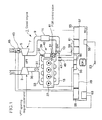
- Fig. 1 is a schematic diagram illustrating an entire construction of a control unit of an internal combustion engine according to a first embodiment of the present invention.
- the diesel engine (engine) 1 comprises an exhaust gas turbine 3 and an exhaust gas turbocharger 7 having a compressor 5 which is coaxially driven by the exhaust gas turbine 3. Air discharged from the compressor 5 of the exhaust gas turbocharger 7 is passed through an intake passage 9 into an intercooler 11, and the intake gas is cooled. Then, the intake flow rate is regulated by means of an intake throttle valve 13, and thereafter the intake gas is flown into a combustion chamber, which is not shown, of the engine 1 from an intake manifold 15.
- the exhaust gas turbocharger 7 is a turbocharger provided with a variable flow mechanism (VFT), a specific construction of which is shown in Fig. 3 .
- VFT variable flow mechanism
- the exhaust turbocharger 7 comprises an inner scroll 19 which continuously extends circumferentially around a turbine rotor, and an outer scroll 21, and further comprises a VFT control valve 23 which is a switching part for switching a mode where the exhaust gas is flown into only the inner scroll 19 and a mode where the exhaust gas is flown into both the inner scroll 19 and the outer scroll 21.
- VFT control valve 23 By actuating the VFT control valve 23, the mode where the exhaust gas is flown into only the inner scroll 19 and the mode where the exhaust gas is flown into both the inner scroll 19 and the outer scroll 21 can be switched.
- the engine 1 is provided with a fuel injection device 29 which is configured to regulate the injection timing and the injection amount through a fuel injection valve 27 and to inject fuel into the combustion chamber.
- the combustion gas combusted in the combustion chamber of the engine 1, i.e. exhaust gas 31, is passed through exhaust ports provided for respective cylinders, an exhaust manifold 33 which aggregates the exhaust ports, and an exhaust passage 35, and then drives the exhaust gas turbine 3 of the exhaust gas turbocharger 7 to become a power source for the compressor 5, and is exhausted through the exhaust passage 35 and an exhaust gas aftertreatment device (not shown).
- an EGR passage 37 is branched from the exhaust passage 35 or the exhaust manifold 33, and on the downstream side of the intake throttle valve 13, an EGR apparatus 40 to which a part of the exhaust gas is input through an EGR cooler 39 and an EGR control valve 41, is provided.
- an air flow meter 43 and an air temperature sensor 45 are provided on the upstream side of the exhaust gas turbocharger 7.
- an intake temperature sensor 47 and a supercharging pressure sensor 49 are provided within the intake manifold 15.
- an engine rotational speed sensor 51 and an air pressure sensor 53 are provided. Signals from the respective sensors are received by a control unit (EUC) 57 via a signal converter 55.
- EUC control unit
- a drive signal is output to the EGR control valve 41 via an EGR valve control part (EGR control part) 59, and an EGR valve opening degree signal is input into the control unit 57.
- a drive signal is output to the intake throttle valve 13 via a throttle valve drive circuit 61, and a throttle valve opening degree signal is input into the control unit 57.
- a drive signal is output to the VFT control valve 23 (see Fig. 3 ) which constitutes the variable flow mechanism via a VFT valve control part (supercharger control unit) 63, and a valve opening degree signal of the VFT control valve 23 is input into the control unit 57.
- Fig. 2 is a block diagram illustrating an internal constitution of the control unit 57 of the internal combustion engine according to the first embodiment of the present invention.
- the control unit 57 a coordinate control of the opening degree control of the EGR control valve 41 and the VFT control valve 23 is performed.
- a target supercharging pressure r1 is obtained by using a target supercharging pressure map 67 based on the engine rotational speed by the engine rotational speed sensor 51 and the fuel injection amount by the fuel injection device 29, which represent the operating status of the engine 1.
- An actual supercharging pressure y1 is obtained based on a signal from the supercharging pressure sensor 49.
- a difference e1 between the actual supercharging pressure y1 and the target supercharging pressure r1 set by the target supercharging pressure setting part 65 is calculated by an adder-subtractor 69 and then is input into a PID control section 80 as a supercharging pressure control amount.
- a target supply air oxygen concentration r2 is obtained by using a target supply air oxygen concentration map 75 based on the operation state of the engine 1 such as the engine rotational speed by the engine rotational speed sensor 51 and the fuel injection amount by the fuel injection device 29.
- the state quantity estimation section 77 calculates the actual supply air oxygen concentration and the in-cylinder oxygen excess ratio based on the engine rotational speed by the engine rotational speed sensor 51, the fuel injection amount by the fuel injection device 29, the supercharging pressure by the supercharging pressure sensor 49, the intake manifold temperature by the intake temperature sensor 47, and the intake flow rate by the air flow meter 43, which represent the operating state of the engine 1.
- a difference e2 between the actual supply air oxygen concentration y2 estimated by the state quantity estimation section 77 and the target supply air oxygen concentration r2 set by the target supply air oxygen concentration setting part 73 is calculated by an adder-subtractor 79 and then is input into the PID control section 80 as a supply air oxygen concentration control amount.
- the PID control section 80 generates an opening degree command for the EGR control valve 41 (hereinafter also referred to as “EGR opening degree command”) and an opening degree command for the VFT control valve 23 (hereinafter also referred to as "VFT opening degree command”) based on the input supercharging pressure control amount e1 and the supply air oxygen concentration control amount e2 so as to bring the actual supercharging pressure r1 to the target supercharging pressure y1 as well as bring the actual supply air oxygen concentration r2 to the target supply air oxygen concentration y2. As described above, the PID control section 80 performs a coordinate control of the EGR control valve 41 and the control of the VFT control valve 23.
- the ⁇ limit control section 81 generates switching commands (an EGR switching command and a VFT switching command) for the EGR control valve opening degree command and the VFT control valve opening degree command, respectively, generated by the PID control section 80, based on the determination result of the transient state, which will be described below.
- the EGR control command generated by the PID control section 80 is switched by the EGR switching command generated by the ⁇ limit control section 81, and then is output as an opening degree command signal for the EGR control valve 41 while the upper and the lower limits are limited by an EGR command value limiter 91.
- the VFT control command generated by the PID control section 80 is switched by the VFT switching command generated by the ⁇ limit control section 81, and then is output as an opening degree command signal for the VFT control valve 23 while the upper and the lower limits are limited by an VFT command value limiter 97.
- Fig. 4 is a block diagram illustrating an internal constitution related to a switching control of the ⁇ limit control section 81 according to the present invention. As illustrated in Fig. 4 , the in-cylinder oxygen excess ratio ⁇ O 2 input into the ⁇ limit control section 81 is then input into comparators 101, 102 and 104 respectively, and the actual supercharging pressure is input into an adder-subtractor 106.
- a first determination section 110 whether the in-cylinder oxygen excess ratio ⁇ O 2 is not greater than a predetermined ⁇ O 2 limit value (e.g. not greater than 2) is determined by the comparator 101.
- the ⁇ O 2 limit value is an example of the "first threshold value" according to the present invention, and it is a threshold value for detecting a decrease in the in-cylinder oxygen excess ratio at the time of occurrence of the transient state. That is, by the first determination section 110, in view of the fact that the in-cylinder oxygen excess ratio temporarily decreases in the transient state, whether the input in-cylinder oxygen excess ratio is not greater than a first threshold value is determined, whereby whether the transient status is present is determined.
- the operating state of the engine 1 such as the engine rotational speed and the fuel injection amount is obtained, which is omitted in Fig. 4 , and a corresponding optimum value of the in-cylinder oxygen excess ratio is output and then input into an adder-subtractor 105.
- a ⁇ O 2 offset value which is an example of the "second threshold value" according to the present invention is input into the adder-subtractor 105 to generate a difference from the optimum value of the in-cylinder oxygen excess ratio ⁇ O 2 , and whether the in-cylinder oxygen excess ratio ⁇ O 2 is not less than the difference is determined by the comparator 102. That is, by the second determination section 112, in view of the fact that in the transient state, the incylinder oxygen excess ratio becomes away from the optimum value defined based on the operating state of the engine 1, whether the in-cylinder oxygen excess ratio difference between the in-cylinder oxygen excess ratio and the optimum value thereof is not less than the second threshold value is determined, whereby whether the transient status is present is determined.
- the third determination section 114 having a target supercharging pressure map 108 defining the optimum value of the supercharging pressure for the operating state of the engine 1, the operating state of the engine 1 such as the engine rotational speed and the fuel injection amount is obtained, which is omitted in Fig. 4 , and a corresponding optimum value of the target supercharging pressure is output and then input into an adder-subtractor 106. Meanwhile, the actual supercharging pressure is input into the adder-subtractor 106 to generate a difference from the target supercharging pressure, and whether the difference is not less than the predetermined supercharging pressure difference limit value (which is an example of the "third threshold value" according to the present invention) is determined by the comparator 103.
- the predetermined supercharging pressure difference limit value which is an example of the "third threshold value" according to the present invention
- the third determination section 114 in view of the fact that in the transient state, the supercharging pressure becomes away from the optimum value defined based on the operating state of the engine 1, whether the supercharging pressure difference between the supercharging pressure and the optimum value thereof is not less than the third threshold value, is determined, whereby whether the transient status is present is determined.
- the determination results by the first determination section 110, the second determination section 112 and the third determination section 114 are input into an AND circuit 118, and when all of the above determination sections determine that the engine 1 is in the transient state, a switching command is output via an OR circuit 120.
- determining the transient state multiply based on different conditions by the first determination section 110, the second determination section 112 and the third determination section 114 as described above, it is possible to determine whether the transient status is present accurately.
- the in-cylinder oxygen excess ratio ⁇ O 2 input into the ⁇ limit control section 81 and a predetermined ⁇ O 2 lower limit are input into a comparator 104, and whether the in-cylinder oxygen excess ratio ⁇ O 2 is not greater than the ⁇ O 2 lower limit.
- the ⁇ O 2 lower limit is a threshold value which is set to be smaller than the ⁇ O 2 limit value (the first threshold value) in the first determination section 110, and is a threshold value to determine that the transient state is present when a drastic reduction in the in-cylinder oxygen excess ratio ⁇ O 2 is detected regardless of the determination results by the first determination section 110, the second determination section 112 and the third determination section 114. It is thereby possible to rapidly determine that the transient status is present when a drastic reduction in the in-cylinder oxygen excess ratio ⁇ O 2 is detected.
- a switching command generation section 122 When the engine 1 is determined to be in the transient state as described above, a switching command generation section 122 generates and outputs an EGR switching command and a VFT switching command.
- the EGR switching command is generated by using an EGR opening degree lower limit map 124 which defines the opening degree lower limit of the EGR control valve 41 based on the operating status of the engine 1.
- the operating status of the engine 1 is obtained, and the EGR switching command for switching the EGR control command is generated so as to bring the opening degree of the EGR control valve to the opening degree lower limit based on the EGR opening degree lower limit map 124.
- the VFT switching command is generated so as to bring the opening degree of the VFT control valve 23 to the opening degree lower value (typically zero) regardless of the operating status of the engine 1.
- the EGR control command and the VFT control command are switched to control the opening degree of the EGR control valve 41 and the opening degree of the VFT control valve 23 so that they become smaller than in the normal state.
- the temporary increase in the supply air oxygen concentration and decrease in the incylinder oxygen excess ratio in the transient state can thereby be suppressed, and it is thereby possible to perform a coordinate control which enables reduction in the emission amount of NOx and PM.
- Fig. 5 is a block diagram illustrating an internal constitution related to a cancel control of the switching control in the ⁇ limit control section 81 according to the present invention.
- the cancel control of the switching control whether the engine 1 is not in the transient state is determined by the first determination section 110 and the second determination section 112. That is, in the first determination section 110, whether the in-cylinder oxygen excess ratio ⁇ O 2 is greater than the predetermined ⁇ O 2 limit value (e.g. not greater than 2) is determined by the comparator 101. Further, in the second determination section 112, whether the incylinder oxygen excess ratio difference between the in-cylinder oxygen excess ratio and the optimum value thereof is less than the second threshold is determined.
- the predetermined ⁇ O 2 limit value e.g. not greater than 2
- the determination results by the respective determination sections are input into an OR circuit 126, whereby the switching control is canceled if either of the determination sections determines the engine 1 not to be in the transient state. It is thereby possible to rapidly cancel the switching control when the normal state comes back from the transient state.
- the first determination section 110 and the second determination section 112 are examples of the "fourth determination part" and the "fifth determination part” according to the present invention, respectively.
- the "fourth threshold value” and the “fifth threshold value” according to the present invention are set to be equal to the "first threshold value” and the “second threshold value” according to the present invention, respectively; however, they may be different from each other, respectively.
- the temporary increase in the supply air oxygen concentration and decrease in the incylinder oxygen excess ratio in the transient state can be suppressed, whereby it is possible to perform a coordinate control which enables reduction of the emission amounts of NOx and PM.
- a control unit of an internal combustion engine according to a second embodiment will be described.
- the same elements as those of the first embodiment are assigned with the same reference numerals as those of the first embodiment, and the same description thereof will be omitted.
- Fig. 6 is a block diagram illustrating an internal constitution of a PID control part 80 of a control unit of an internal combustion engine according to a second embodiment of the present invention.
- the difference e1 between the actual supercharging pressure y1 and the target supercharging pressure r1 set by the target supercharging pressure setting part 65, and the difference e2 between the supply air oxygen concentration y2 estimated by the state quantity estimation section 77 and the target supply air oxygen concentration r2 set by the target supply air oxygen concentration setting part 73 are input into the PID control section 80.
- the PID control section 80 outputs a VFT opening degree command based on the input difference e1 as well as an EGR opening degree command based on the difference e2.
- Fig. 6 illustrate a case where after a prescribed gain 130 is applied based on the difference e2, the EGR opening degree command is output via an integrator 132.
- a S/W 134 is a switching part which outputs a reset signal when the ⁇ limit control signal is in the ON-state (i.e. when the switching control is performed).
- the integrator 132 resets an integrated value of the gain 130 and outputs an EGR control valve command so as to bring the EGR control valve 41 to the prescribed opening degree.
- a control unit of an internal combustion engine according to a third embodiment will be described.
- the same elements as those of the first or second embodiment are assigned with the same reference numerals as those of the first or second embodiment, and the same description thereof will be omitted.
- Fig. 7 is a block diagram illustrating a constitution around a VFT command value limiter 97 of a control unit of an internal combustion engine according to a third embodiment of the present invention.
- the VFT command value limiter 97 is an example of the "supercharging command signal limiting part" according to the present invention and is for limiting the VFT opening degree command to a range defined by an upper limit set by an upper limit setting part 136 and a lower limit set by a lower limit setting part 138.
- the range set by the upper limit setting part 136 and the lower limit setting part 138 is the range of the opening degree of the VFT valve 23 which is allowed in the normal state of the engine 1, and the upper limit and the lower limit are defined depending upon the operating status of the engine 1 by a VFT maximum opening degree map 140 and a VFT minimum opening degree map 142, respectively.
- the opening degree of the VFT control valve 23 is under a feedback control
- the VFT opening degree signal is a decreasing command as above
- the transient state e.g. sudden acceleration of a vehicle
- the time lag until the supercharging pressure is turned upward will be increased.
- the in-cylinder oxygen excess ratio will be decreased in the transient state, and the PM in the exhaust gas will be increased, which may lead to a problem.
- the opening degree of the VFT control valve 23 is brought to the opening degree in the steady state of the engine 1 to cause the supercharging pressure not to be excessively decreased, whereby it is possible to suppress the time lag at the time of occurrence of the transient state, thereby to suppress the increase of PM.
- the present invention relates to a control unit of an internal combustion engine and is applicable particularly to a coordinate control of an exhaust gas recirculation (hereinafter abbreviated as "EGR") control by an EGR apparatus of an internal combustion engine and a supercharger control by a supercharger provided with a variable flow mechanism.
- EGR exhaust gas recirculation
Landscapes
- Engineering & Computer Science (AREA)
- Chemical & Material Sciences (AREA)
- Combustion & Propulsion (AREA)
- Mechanical Engineering (AREA)
- General Engineering & Computer Science (AREA)
- Output Control And Ontrol Of Special Type Engine (AREA)
- Exhaust-Gas Circulating Devices (AREA)
- Electrical Control Of Air Or Fuel Supplied To Internal-Combustion Engine (AREA)
- Supercharger (AREA)
Abstract
Description
- The present invention relates to a control unit of an internal combustion engine, particularly to a coordinate control of an exhaust gas recirculation (hereinafter abbreviated as "EGR") control by an EGR apparatus of an internal combustion engine and a supercharger control by a supercharger provided with a variable flow mechanism.
- An internal combustion engine which comprises a supercharger control device capable of controlling the supercharging amount or the supercharging pressure of a super charger provided with a variable flow mechanism, and an exhaust gas recirculation (EGR) apparatus which recirculates a part of the exhaust gas into an intake passage or a cylinder, is known. In such an internal combustion engine, particularly in a diesel engine, by controlling the supercharger provided with a variable flow mechanism, the discharge pressure is increased and then the recirculation amount of the exhaust gas by EGR is increased, whereby the intake flow and the supply air oxygen concentration will not be ensured, and thus smoke (PM) will be increasingly generated; or the discharge pressure is decreased, whereby the recirculation amount of the EGR gas will not be ensured, and thus an effect of reducing NOx will not be obtained, for example. That is, there is a relationship between the control of EGR and the control of the supercharger provided with a variable flow mechanism where they have influence on each other.
- In this regard, a technique of controlling the EGR control and the supercharger control in a coordinated manner is known. An example of coordinate control of this type is described in
Patent Document 1. InPatent Document 1, it is disclosed that in a operating region where exhaust gas recirculation (EGR) is carried out, by feeding back the EGR control valve so as to bring the air-fuel ratio to the target air-fuel ratio while adjusting the opening degree of the variable flow mechanism to be within a predetermined range, it is possible to reduce NOx and PM. - [PTL 1]
JP 2000-110574 A - However, in
Patent Document 1, as the exhaust gas recirculation is carried out in a partial load region, it is not possible to reduce NOx and PM by a coordinate control in other load regions. Further, PM emission amount depends largely on the in-cylinder oxygen excess ratio; however, the in-cylinder oxygen excess ratio is not taken into consideration as a control parameter in the coordinate control described inPatent Document 1, which leaves room for improvement. - Thus, such coordinate control of the EGR control and the supercharger control is not sufficient. Particularly, with regard to a transient state where the fuel injection amount in each cylinder is varied with time due to change of load of the internal combustion engine, there are problems described hereinafter.
Fig. 8 includes charts showing transition of the fuel injection amount, supply air oxygen concentration, in-cylinder oxygen excess ratio, NOx emission amount, and PM emission amount, in the transient state. As shown in (a) ofFig. 8 , with increase in the load of the internal combustion engine at the time T1, the fuel infection amount is increased and gets under a feedback control so as to accord with a new target fuel injection amount. When the fuel injection amount is increased as above, the intake amount is also increased; and therefore the supply air oxygen concentration and the in-cylinder oxygen excess ratio are temporarily decreased and then increased, and then get under a feedback control so as to accord with a new supply air oxygen concentration. As shown in (b) ofFig. 8 , in the transient state, as the supply air oxygen concentration is temporarily increased, NOx contained in the exhaust gas is increased, which leads to a problem. Further, as shown in (c) ofFig. 8 , in the transient state, as the in-cylinder oxygen excess ratio is temporarily decreased, PM contained in the exhaust gas is increased, which leads to a problem. - The present invention has been made in view of the above problems and is to provide a control unit of an internal combustion engine capable of performing coordinate control of the EGR control and the supercharger control so that NOx and PM in the exhaust gas in the transient state where the load of the internal combustion engine is varied, can be suppressed.
- To solve the above problems, the present invention provides a control unit of an internal combustion engine comprising:
- an exhaust gas recirculation (EGR) control part for sending an EGR command signal so as to bring an EGR gas supply amount by an EGR apparatus to a target EGR gas supply amount to control an opening degree of an EGR valve;
- a supercharger control part for sending a supercharging command signal so as to bring a supercharging amount of a supercharger provided with a variable flow mechanism to a target supercharging amount to control an opening degree of the variable flow mechanism;
- an in-cylinder oxygen excess ratio calculation part for calculating an incylinder oxygen excess ratio based on an operating state of the internal combustion engine;
- a transient state determination part for determining whether the internal combustion engine is in a transient state based on the oxygen excess ratio in the cylinder calculated by the in-cylinder oxygen excess ratio calculation part; and
- a switching part for switching the EGR command signal and the supercharging command signal so that the opening degree of the EGR valve and the opening degree of the variable flow mechanism become smaller than in a normal state when the internal combustion engine is determined to be in the transient state by the transient state determination part.
- According to the present invention, when the transient state of the internal combustion engine is detected based on the in-cylinder oxygen excess ratio, the EGR command signal and the supercharging command signal are switched by the switching part, whereby the opening degree of the EGR valve and the opening degree of the variable flow mechanism are controlled so that they become smaller than in the normal state. It is thereby possible to suppress temporary increase in the supply air oxygen concentration or temporary decrease in the in-cylinder oxygen excess ratio in the transient state, and therefore to perform a coordinate control which enables reduction of emission amounts of NOx and PM.
- The switching part may be configured to switch the EGR command signal and the supercharging command signal so as to bring the opening degree of the EGR valve to a lower limit which is preliminarily set and the opening degree of the variable flow mechanism to a lower limit which is preliminarily set. According to such a configuration, by controlling the opening degree of the EGR valve and the opening degree of the variable flow mechanism so that they are brought to their lower limits, it is possible to suppress temporary increase in the supply air oxygen concentration or temporary decrease in the in-cylinder oxygen excess ratio in the transient state, and therefore to reduce the emission amounts of NOx and PM.
- In this case, it is preferred that the lower limit of the opening degree of the EGR valve is preliminarily set depending upon the operating state of the internal combustion engine. The lower limit of the opening degree of the EGR valve is set to a finite value, which is not zero, depending upon the operating state, whereby it is possible to suppress the emission amounts of NOx and PM while a good operating efficiency of the internal combustion engine is maintained.
- The transient state determination part may comprise:
- a first determination part for determining whether the in-cylinder oxygen excess ratio calculated by the in-cylinder oxygen excess ratio calculation part is not greater than a first threshold value; and
- a second determination part for determining whether an in-cylinder oxygen excess ratio difference between the in-cylinder oxygen excess ratio calculated by the in-cylinder oxygen excess ratio calculation part and an optimum value of the incylinder oxygen excess ratio which is preliminarily set on the basis of the operating state of the internal combustion engine is not less than a second threshold value;
- and may be configured to determine the internal combustion engine to be in the transient state when the first determination part determines that the in-cylinder oxygen excess ratio is not greater than the first threshold value and the second determination part determines that the in-cylinder oxygen excess ratio difference is not less than the second threshold value.
- In view of the fact that the in-cylinder oxygen excess ratio temporarily decreases in the transient state, the first determination part determines whether the in-cylinder oxygen excess ratio calculated by the in-cylinder oxygen excess ratio calculation part is not greater than a first threshold value, thereby to determine whether the transient status is present. Meanwhile, in view of the fact that in the transient state, the in-cylinder oxygen excess ratio becomes away from the optimum value defined based on the operating state of the internal combustion engine, the second determination part determines whether the in-cylinder oxygen excess ratio difference between the in-cylinder oxygen excess ratio and the optimum value thereof is not less than the second threshold value, thereby to determine whether the transient status is present. Particularly, according to the above embodiment, an accurate determination can be done by determining that the transient state is present when both the above first determination part and the second determination part determine that the internal combustion engine is in the transient state.
- In this case, the transient state determination part may comprise a third determination part for determining whether a supercharging pressure difference between a supercharging pressure of the supercharger and an optimum value of the supercharging pressure which is preliminarily set on the basis of the operating state of the internal combustion engine is not less than a third threshold value, and may be configured to determine the internal combustion engine to be in the transient state when the third determination part further determines that the supercharging pressure difference is not less than. In view of the fact that in the transient state, the supercharging pressure becomes away from the optimum value defined based on the operating state of the internal combustion engine, the third determination part further determines whether the supercharging pressure difference between the supercharging pressure and the optimum value thereof is not less than the third threshold value, thereby to determine whether the transient status is present. It is thereby possible to detect the transient status more accurately.
- The switching part may be configured to cancel a switching control of the EGR command signal and the supercharging command signal when the internal combustion engine is determined not to be in the transient state by the transient state determination part. According to this configuration, when the transient state determination part determines that the transient state ends, the switching control by the switching part will be cancelled, and the normal operating status will be resumed.
- In this case, the transient state determination part may comprise:
- a fourth determination part for determining whether the in-cylinder oxygen excess ratio calculated by the in-cylinder oxygen excess ratio calculation part is greater than a fourth threshold value; and
- a fifth determination part for determining whether an in-cylinder oxygen excess ratio difference between the in-cylinder oxygen excess ratio calculated by the in-cylinder oxygen excess ratio calculation part and an optimum value of the incylinder oxygen excess ratio which is preliminarily set on the basis of the operating state of the internal combustion engine is less than a fifth threshold value;
- and may be configured to determine the internal combustion engine not to be in the transient state when the fourth determination part determines that the incylinder oxygen excess ratio is greater than the fourth threshold value or the fifth determination part determines that the in-cylinder oxygen excess ratio difference is less than the fifth threshold value. According to this configuration, the normal state can be rapidly resumed when either the above fourth determination part or the fifth determination part determines that the internal combustion engine is not in the transient state. The fourth threshold value and the fifth threshold value may be set to be the same as the above first threshold value and the second threshold value, respectively, or to be different from the above first threshold value or the second threshold value.
- The switching part may be configured to reset the EGR command signal upon canceling the switching control so as to bring the opening degree of the EGR valve to a prescribed opening degree which is larger than the opening degree at the time of the switching control. When the transient state ends and the normal operating state is resumed, a delay may be caused until the opening degree of the EGR valve which has been closed by the switching control in the transient state is increased, whereby the supply air oxygen concentration may be increased, and therefore NOx may be increased. In this embodiment, it is possible to control the opening degree of the EGR valve so as to bring the opening degree to the prescribed opening degree at the end of the transient state to rapidly increase the opening degree of the EGR valve, whereby it is possible to prevent the increase of NOx.
- Further, the control unit of an internal combustion engine may further comprise a supercharging command signal limiting part for limiting the supercharging command signal so as to bring the opening degree of the variable flow mechanism to an opening degree in a steady state of the internal combustion engine. In general, in a case where the opening degree of a supercharger is under a feedback control, when the actual supercharging pressure is higher than the target supercharging pressure, a supercharging command signal to decrease the supercharging pressure is generated. When the supercharging signal is a decreasing command as above, if the transient state (e.g. sudden acceleration of a vehicle) occurs in which the load of the internal combustion engine is increased, the time lag until the supercharging pressure is turned upward will be increased. Then, the incylinder oxygen excess ratio will be decreased in the transient state, and the PM in the exhaust gas will be increased, which may lead to a problem. According to the above embodiment, by limiting the supercharging command signal so as to bring the opening degree of the variable flow mechanism to an opening degree in a steady state of the internal combustion engine, the opening degree of the variable flow mechanism is prospectively maintained at the opening degree in the normal state so that the supercharging pressure will not be excessively decreased, whereby it is possible to suppress the time lag at the time of occurrence of the transient state, thereby to suppress the increase of PM.
- According to the present invention, when the transient state of the internal combustion engine is detected on the basis of the in-cylinder oxygen excess ratio, the EGR command signal and the supercharging command signal are switched by the switching part, whereby the opening degree of the EGR valve and the opening degree of the variable flow mechanism are controlled so that they become smaller than in the normal state. It is thereby possible to suppress temporary increase in the supply air oxygen concentration or temporary decrease in the in-cylinder oxygen excess ratio in the transient state, and therefore to perform a coordinate control which enables reduction of emission amounts of NOx and PM.
-
- [
FIG.1] Fig. 1 is a schematic diagram illustrating an entire construction of a control unit of an internal combustion engine according to a first embodiment of the present invention. - [
FIG.2] Fig. 2 is a block diagram illustrating an internal constitution of a control unit of an internal combustion engine according to the first embodiment of the present invention. - [
FIG.3] Fig. 3 is a cross-sectional view of a major part of a supercharger provided with a variable flow mechanism. - [
FIG.4] Fig. 4 is a block diagram illustrating an internal constitution related to a switching control of the λ limit control section. - [
FIG.5] Fig. 5 is a block diagram illustrating an internal constitution related to a switching cancel control of the λ limit control section. - [
FIG.6] Fig. 6 is a block diagram illustrating an internal constitution of aPID control part 80 of a control unit of an internal combustion engine according to a second embodiment of the present invention. - [
FIG.7] Fig. 7 is a block diagram illustrating a constitution around a VFT command value limiter of a control unit of an internal combustion engine according to a third embodiment of the present invention. - [
FIG.8] Fig. 8 is a chart showing transition of a fuel injection amount, supply air oxygen concentration, intake air oxygen excess ratio, NOx emission amount, and PM emission amount, in the transient state according to a conventional art. - Embodiments of the present invention will now be described in detail with reference to the accompanying drawings. It is intended, however, that unless particularly specified, dimensions, materials, shapes, relative positions and the like of components described in the embodiments shall be interpreted as illustrative only and not limitative of the scope of the present invention.
-
Fig. 1 is a schematic diagram illustrating an entire construction of a control unit of an internal combustion engine according to a first embodiment of the present invention. The diesel engine (engine) 1 comprises anexhaust gas turbine 3 and anexhaust gas turbocharger 7 having acompressor 5 which is coaxially driven by theexhaust gas turbine 3. Air discharged from thecompressor 5 of theexhaust gas turbocharger 7 is passed through anintake passage 9 into anintercooler 11, and the intake gas is cooled. Then, the intake flow rate is regulated by means of anintake throttle valve 13, and thereafter the intake gas is flown into a combustion chamber, which is not shown, of theengine 1 from anintake manifold 15. - The
exhaust gas turbocharger 7 is a turbocharger provided with a variable flow mechanism (VFT), a specific construction of which is shown inFig. 3 . As illustrated inFig. 3 , theexhaust turbocharger 7 comprises aninner scroll 19 which continuously extends circumferentially around a turbine rotor, and anouter scroll 21, and further comprises aVFT control valve 23 which is a switching part for switching a mode where the exhaust gas is flown into only theinner scroll 19 and a mode where the exhaust gas is flown into both theinner scroll 19 and theouter scroll 21. By actuating theVFT control valve 23, the mode where the exhaust gas is flown into only theinner scroll 19 and the mode where the exhaust gas is flown into both theinner scroll 19 and theouter scroll 21 can be switched. - Further, as illustrated in
Fig. 1 , theengine 1 is provided with afuel injection device 29 which is configured to regulate the injection timing and the injection amount through afuel injection valve 27 and to inject fuel into the combustion chamber. The combustion gas combusted in the combustion chamber of theengine 1, i.e.exhaust gas 31, is passed through exhaust ports provided for respective cylinders, anexhaust manifold 33 which aggregates the exhaust ports, and anexhaust passage 35, and then drives theexhaust gas turbine 3 of theexhaust gas turbocharger 7 to become a power source for thecompressor 5, and is exhausted through theexhaust passage 35 and an exhaust gas aftertreatment device (not shown). - Further, an
EGR passage 37 is branched from theexhaust passage 35 or theexhaust manifold 33, and on the downstream side of theintake throttle valve 13, anEGR apparatus 40 to which a part of the exhaust gas is input through anEGR cooler 39 and anEGR control valve 41, is provided. - On the upstream side of the
exhaust gas turbocharger 7, anair flow meter 43 and anair temperature sensor 45 are provided. Within theintake manifold 15, anintake temperature sensor 47 and a superchargingpressure sensor 49 are provided. Further, an enginerotational speed sensor 51 and anair pressure sensor 53 are provided. Signals from the respective sensors are received by a control unit (EUC) 57 via asignal converter 55. - Further, a drive signal is output to the
EGR control valve 41 via an EGR valve control part (EGR control part) 59, and an EGR valve opening degree signal is input into thecontrol unit 57. Similarly, a drive signal is output to theintake throttle valve 13 via a throttlevalve drive circuit 61, and a throttle valve opening degree signal is input into thecontrol unit 57. Further, with regard to theexhaust gas turbocharger 7, a drive signal is output to the VFT control valve 23 (seeFig. 3 ) which constitutes the variable flow mechanism via a VFT valve control part (supercharger control unit) 63, and a valve opening degree signal of theVFT control valve 23 is input into thecontrol unit 57. -
Fig. 2 is a block diagram illustrating an internal constitution of thecontrol unit 57 of the internal combustion engine according to the first embodiment of the present invention. In thecontrol unit 57, a coordinate control of the opening degree control of theEGR control valve 41 and theVFT control valve 23 is performed. - As illustrated in
Fig. 2 , by means of a target superchargingpressure setting part 65, a target supercharging pressure r1 is obtained by using a targetsupercharging pressure map 67 based on the engine rotational speed by the enginerotational speed sensor 51 and the fuel injection amount by thefuel injection device 29, which represent the operating status of theengine 1. An actual supercharging pressure y1 is obtained based on a signal from the superchargingpressure sensor 49. Then, a difference e1 between the actual supercharging pressure y1 and the target supercharging pressure r1 set by the target superchargingpressure setting part 65 is calculated by an adder-subtractor 69 and then is input into aPID control section 80 as a supercharging pressure control amount. - Similarly, with regard to the supply air oxygen concentration, by means of a target supply air oxygen
concentration setting part 73, a target supply air oxygen concentration r2 is obtained by using a target supply air oxygen concentration map 75 based on the operation state of theengine 1 such as the engine rotational speed by the enginerotational speed sensor 51 and the fuel injection amount by thefuel injection device 29. - As the actual supply air oxygen concentration and the in-cylinder oxygen excess ratio, values calculated by a state
quantity estimation section 77 are used. The statequantity estimation section 77 calculates the actual supply air oxygen concentration and the in-cylinder oxygen excess ratio based on the engine rotational speed by the enginerotational speed sensor 51, the fuel injection amount by thefuel injection device 29, the supercharging pressure by the superchargingpressure sensor 49, the intake manifold temperature by theintake temperature sensor 47, and the intake flow rate by theair flow meter 43, which represent the operating state of theengine 1. Then, a difference e2 between the actual supply air oxygen concentration y2 estimated by the statequantity estimation section 77 and the target supply air oxygen concentration r2 set by the target supply air oxygenconcentration setting part 73 is calculated by an adder-subtractor 79 and then is input into thePID control section 80 as a supply air oxygen concentration control amount. - The
PID control section 80 generates an opening degree command for the EGR control valve 41 (hereinafter also referred to as "EGR opening degree command") and an opening degree command for the VFT control valve 23 (hereinafter also referred to as "VFT opening degree command") based on the input supercharging pressure control amount e1 and the supply air oxygen concentration control amount e2 so as to bring the actual supercharging pressure r1 to the target supercharging pressure y1 as well as bring the actual supply air oxygen concentration r2 to the target supply air oxygen concentration y2. As described above, thePID control section 80 performs a coordinate control of theEGR control valve 41 and the control of theVFT control valve 23. - Meanwhile, the in-cylinder oxygen excess ratio estimated by the state
quantity estimation section 77 and the actual supercharging pressure by the superchargingpressure sensor 49 are input into a λlimit control section 81. The λlimit control section 81 generates switching commands (an EGR switching command and a VFT switching command) for the EGR control valve opening degree command and the VFT control valve opening degree command, respectively, generated by thePID control section 80, based on the determination result of the transient state, which will be described below. - The EGR control command generated by the
PID control section 80 is switched by the EGR switching command generated by the λlimit control section 81, and then is output as an opening degree command signal for theEGR control valve 41 while the upper and the lower limits are limited by an EGRcommand value limiter 91. Similarly, the VFT control command generated by thePID control section 80 is switched by the VFT switching command generated by the λlimit control section 81, and then is output as an opening degree command signal for theVFT control valve 23 while the upper and the lower limits are limited by an VFTcommand value limiter 97. -
Fig. 4 is a block diagram illustrating an internal constitution related to a switching control of the λlimit control section 81 according to the present invention. As illustrated inFig. 4 , the in-cylinder oxygen excess ratio λO2 input into the λlimit control section 81 is then input intocomparators subtractor 106. - In a
first determination section 110, whether the in-cylinder oxygen excess ratio λO2 is not greater than a predetermined λO2 limit value (e.g. not greater than 2) is determined by thecomparator 101. The λO2 limit value is an example of the "first threshold value" according to the present invention, and it is a threshold value for detecting a decrease in the in-cylinder oxygen excess ratio at the time of occurrence of the transient state. That is, by thefirst determination section 110, in view of the fact that the in-cylinder oxygen excess ratio temporarily decreases in the transient state, whether the input in-cylinder oxygen excess ratio is not greater than a first threshold value is determined, whereby whether the transient status is present is determined. - In the
second determination section 112 having a λO2 map 107 defining the optimum value of the in-cylinder oxygen excess ratio for the operating state of theengine 1, the operating state of theengine 1 such as the engine rotational speed and the fuel injection amount is obtained, which is omitted inFig. 4 , and a corresponding optimum value of the in-cylinder oxygen excess ratio is output and then input into an adder-subtractor 105. Meanwhile, a λO2 offset value which is an example of the "second threshold value" according to the present invention is input into the adder-subtractor 105 to generate a difference from the optimum value of the in-cylinder oxygen excess ratio λO2, and whether the in-cylinder oxygen excess ratio λO2 is not less than the difference is determined by thecomparator 102. That is, by thesecond determination section 112, in view of the fact that in the transient state, the incylinder oxygen excess ratio becomes away from the optimum value defined based on the operating state of theengine 1, whether the in-cylinder oxygen excess ratio difference between the in-cylinder oxygen excess ratio and the optimum value thereof is not less than the second threshold value is determined, whereby whether the transient status is present is determined. - In the
third determination section 114 having a targetsupercharging pressure map 108 defining the optimum value of the supercharging pressure for the operating state of theengine 1, the operating state of theengine 1 such as the engine rotational speed and the fuel injection amount is obtained, which is omitted inFig. 4 , and a corresponding optimum value of the target supercharging pressure is output and then input into an adder-subtractor 106. Meanwhile, the actual supercharging pressure is input into the adder-subtractor 106 to generate a difference from the target supercharging pressure, and whether the difference is not less than the predetermined supercharging pressure difference limit value (which is an example of the "third threshold value" according to the present invention) is determined by thecomparator 103. That is, by thethird determination section 114, in view of the fact that in the transient state, the supercharging pressure becomes away from the optimum value defined based on the operating state of theengine 1, whether the supercharging pressure difference between the supercharging pressure and the optimum value thereof is not less than the third threshold value, is determined, whereby whether the transient status is present is determined. - The determination results by the
first determination section 110, thesecond determination section 112 and thethird determination section 114 are input into an ANDcircuit 118, and when all of the above determination sections determine that theengine 1 is in the transient state, a switching command is output via an ORcircuit 120. By determining the transient state multiply based on different conditions by thefirst determination section 110, thesecond determination section 112 and thethird determination section 114 as described above, it is possible to determine whether the transient status is present accurately. - By the
fourth determination section 116, the in-cylinder oxygen excess ratio λO2 input into the λlimit control section 81 and a predetermined λO2 lower limit are input into acomparator 104, and whether the in-cylinder oxygen excess ratio λO2 is not greater than the λO2 lower limit. The λO2 lower limit is a threshold value which is set to be smaller than the λO2 limit value (the first threshold value) in thefirst determination section 110, and is a threshold value to determine that the transient state is present when a drastic reduction in the in-cylinder oxygen excess ratio λO2 is detected regardless of the determination results by thefirst determination section 110, thesecond determination section 112 and thethird determination section 114. It is thereby possible to rapidly determine that the transient status is present when a drastic reduction in the in-cylinder oxygen excess ratio λO2 is detected. - When the
engine 1 is determined to be in the transient state as described above, a switchingcommand generation section 122 generates and outputs an EGR switching command and a VFT switching command. The EGR switching command is generated by using an EGR opening degreelower limit map 124 which defines the opening degree lower limit of theEGR control valve 41 based on the operating status of theengine 1. In this embodiment, the operating status of theengine 1 is obtained, and the EGR switching command for switching the EGR control command is generated so as to bring the opening degree of the EGR control valve to the opening degree lower limit based on the EGR opening degreelower limit map 124. On the other hand, the VFT switching command is generated so as to bring the opening degree of theVFT control valve 23 to the opening degree lower value (typically zero) regardless of the operating status of theengine 1. - When the
engine 1 is determined to be in the transient state as described above, the EGR control command and the VFT control command are switched to control the opening degree of theEGR control valve 41 and the opening degree of theVFT control valve 23 so that they become smaller than in the normal state. The temporary increase in the supply air oxygen concentration and decrease in the incylinder oxygen excess ratio in the transient state can thereby be suppressed, and it is thereby possible to perform a coordinate control which enables reduction in the emission amount of NOx and PM. -
Fig. 5 is a block diagram illustrating an internal constitution related to a cancel control of the switching control in the λlimit control section 81 according to the present invention. In the cancel control of the switching control, whether theengine 1 is not in the transient state is determined by thefirst determination section 110 and thesecond determination section 112. That is, in thefirst determination section 110, whether the in-cylinder oxygen excess ratio λO2 is greater than the predetermined λO2 limit value (e.g. not greater than 2) is determined by thecomparator 101. Further, in thesecond determination section 112, whether the incylinder oxygen excess ratio difference between the in-cylinder oxygen excess ratio and the optimum value thereof is less than the second threshold is determined. Then, the determination results by the respective determination sections are input into an OR circuit 126, whereby the switching control is canceled if either of the determination sections determines theengine 1 not to be in the transient state. It is thereby possible to rapidly cancel the switching control when the normal state comes back from the transient state. - The
first determination section 110 and thesecond determination section 112 are examples of the "fourth determination part" and the "fifth determination part" according to the present invention, respectively. Particularly in this embodiment, the "fourth threshold value" and the "fifth threshold value" according to the present invention are set to be equal to the "first threshold value" and the "second threshold value" according to the present invention, respectively; however, they may be different from each other, respectively. - As described above, according to the control unit 54 in the first embodiment, the temporary increase in the supply air oxygen concentration and decrease in the incylinder oxygen excess ratio in the transient state can be suppressed, whereby it is possible to perform a coordinate control which enables reduction of the emission amounts of NOx and PM.
- With reference to
Fig. 6 , a control unit of an internal combustion engine according to a second embodiment will be described. In the description of the second embodiment, the same elements as those of the first embodiment are assigned with the same reference numerals as those of the first embodiment, and the same description thereof will be omitted. -
Fig. 6 is a block diagram illustrating an internal constitution of aPID control part 80 of a control unit of an internal combustion engine according to a second embodiment of the present invention. As described in above First Embodiment, the difference e1 between the actual supercharging pressure y1 and the target supercharging pressure r1 set by the target superchargingpressure setting part 65, and the difference e2 between the supply air oxygen concentration y2 estimated by the statequantity estimation section 77 and the target supply air oxygen concentration r2 set by the target supply air oxygenconcentration setting part 73 are input into thePID control section 80. ThePID control section 80 outputs a VFT opening degree command based on the input difference e1 as well as an EGR opening degree command based on the difference e2. Particularly,Fig. 6 illustrate a case where after aprescribed gain 130 is applied based on the difference e2, the EGR opening degree command is output via anintegrator 132. - On the other hand, a λ limit control signal which indicates whether the above switching control is being performed or not is input into the
PID control section 80 from the λlimit control section 81. A S/W 134 is a switching part which outputs a reset signal when the λ limit control signal is in the ON-state (i.e. when the switching control is performed). When the reset signal is input into theintegrator 132, theintegrator 132 resets an integrated value of thegain 130 and outputs an EGR control valve command so as to bring theEGR control valve 41 to the prescribed opening degree. - With a conventional art, when the transient state ends and the normal operating state comes back, a delay may be caused until the opening degree of the
EGR control valve 41 which has been closed by switching during the transient state is increased, and the supply air oxygen concentration and therefore NOx may be increased. In the above embodiment, when the transient state ends, a control is performed to bring the opening degree of theEGR control valve 41 to the prescribed opening degree, whereby it is possible to rapidly increase the opening degree of theEGR control valve 41 to prevent the increase in NOx. - With reference to
Fig. 7 , a control unit of an internal combustion engine according to a third embodiment will be described. In the description of the third embodiment, the same elements as those of the first or second embodiment are assigned with the same reference numerals as those of the first or second embodiment, and the same description thereof will be omitted. -
Fig. 7 is a block diagram illustrating a constitution around a VFTcommand value limiter 97 of a control unit of an internal combustion engine according to a third embodiment of the present invention. The VFTcommand value limiter 97 is an example of the "supercharging command signal limiting part" according to the present invention and is for limiting the VFT opening degree command to a range defined by an upper limit set by an upperlimit setting part 136 and a lower limit set by a lowerlimit setting part 138. The range set by the upperlimit setting part 136 and the lowerlimit setting part 138 is the range of the opening degree of theVFT valve 23 which is allowed in the normal state of theengine 1, and the upper limit and the lower limit are defined depending upon the operating status of theengine 1 by a VFT maximumopening degree map 140 and a VFT minimumopening degree map 142, respectively. - In general, in a case where the opening degree of the
VFT control valve 23 is under a feedback control, when the actual supercharging pressure is larger than the target supercharging pressure, a VFT opening degree command to decrease the supercharging pressure is generated. When the VFT opening degree signal is a decreasing command as above, if the transient state (e.g. sudden acceleration of a vehicle) occurs in which the load of theengine 1 is increased, the time lag until the supercharging pressure is turned upward will be increased. Then, the in-cylinder oxygen excess ratio will be decreased in the transient state, and the PM in the exhaust gas will be increased, which may lead to a problem. According to this embodiment, by limitation by the VFTcommand value limiter 97, the opening degree of theVFT control valve 23 is brought to the opening degree in the steady state of theengine 1 to cause the supercharging pressure not to be excessively decreased, whereby it is possible to suppress the time lag at the time of occurrence of the transient state, thereby to suppress the increase of PM. - The present invention relates to a control unit of an internal combustion engine and is applicable particularly to a coordinate control of an exhaust gas recirculation (hereinafter abbreviated as "EGR") control by an EGR apparatus of an internal combustion engine and a supercharger control by a supercharger provided with a variable flow mechanism.
Claims (9)
- A control unit of an internal combustion engine comprising:an exhaust gas recirculation (EGR) control part for sending an EGR command signal so as to bring an EGR gas supply amount by an EGR apparatus to a target EGR gas supply amount to control an opening degree of an EGR valve;a supercharger control part for sending a supercharging command signal so as to bring a supercharging amount of a supercharger provided with a variable flow mechanism to a target supercharging amount to control an opening degree of the variable flow mechanism;an in-cylinder oxygen excess ratio calculation part for calculating an incylinder oxygen excess ratio based on an operating state of the internal combustion engine;a transient state determination part for determining whether the internal combustion engine is in a transient state based on the oxygen excess ratio in the cylinder calculated by the in-cylinder oxygen excess ratio calculation part; anda switching part for switching the EGR command signal and the supercharging command signal so that the opening degree of the EGR valve and the opening degree of the variable flow mechanism become smaller than in a normal state when the internal combustion engine is determined to be in the transient state by the transient state determination part.
- The control unit of an internal combustion engine according to claim 1, wherein the switching part is configured to switch the EGR command signal and the supercharging command signal so as to bring the opening degree of the EGR valve to a lower limit which is preliminarily set and the opening degree of the variable flow mechanism to a lower limit which is preliminarily set.
- The control unit of an internal combustion engine according to claim 2, wherein the lower limit of the opening degree of the EGR valve is preliminarily set depending upon the operating state of the internal combustion engine.
- The control unit of an internal combustion engine according to any one of claims 1 to 3, wherein the transient state determination part comprises:a first determination part for determining whether the in-cylinder oxygen excess ratio calculated by the in-cylinder oxygen excess ratio calculation part is not greater than a first threshold value; anda second determination part for determining whether an in-cylinder oxygen excess ratio difference between the in-cylinder oxygen excess ratio calculated by the in-cylinder oxygen excess ratio calculation part and an optimum value of the incylinder oxygen excess ratio which is preliminarily set on the basis of the operating state of the internal combustion engine is not less than a second threshold value;and is configured to determine the internal combustion engine to be in the transient state when the first determination part determines that the in-cylinder oxygen excess ratio is not greater than the first threshold value and the second determination part determines that the in-cylinder oxygen excess ratio difference is not less than the second threshold value.
- The control unit of an internal combustion engine according to claim 4, wherein the transient state determination part comprises a third determination part for determining whether a supercharging pressure difference between a supercharging pressure of the supercharger and an optimum value of the supercharging pressure which is preliminarily set on the basis of the operating state of the internal combustion engine is not less than a third threshold value, and is configured to determine the internal combustion engine to be in the transient state when the third determination part further determines that the supercharging pressure difference is not less than.
- The control unit of an internal combustion engine according to any one of claims 1 to 5, wherein the switching part is configured to cancel a switching control of the EGR command signal and the supercharging command signal when the internal combustion engine is determined not to be in the transient state by the transient state determination part.
- The control unit of an internal combustion engine according to claim 6, wherein the transient state determination part comprises:a fourth determination part for determining whether the in-cylinder oxygen excess ratio calculated by the in-cylinder oxygen excess ratio calculation part is greater than a fourth threshold value; anda fifth determination part for determining whether an in-cylinder oxygen excess ratio difference between the in-cylinder oxygen excess ratio calculated by the in-cylinder oxygen excess ratio calculation part and an optimum value of the incylinder oxygen excess ratio which is preliminarily set on the basis of the operating state of the internal combustion engine is less than a fifth threshold value;and is configured to determine the internal combustion engine not to be in the transient state when the fourth determination part determines that the in-cylinder oxygen excess ratio is greater than the fourth threshold value or the fifth determination part determines that the in-cylinder oxygen excess ratio difference is less than the fifth threshold value.
- The control unit of an internal combustion engine according to claim 6 or 7, wherein the switching part is configured to reset the EGR command signal upon canceling the switching control so as to bring the opening degree of the EGR valve to a prescribed opening degree which is larger than the opening degree at the time of the switching control.
- The control unit of an internal combustion engine according to any one of claims 1 to 8, further comprising a supercharging command signal limiting part for limiting the supercharging command signal so as to bring the opening degree of the variable flow mechanism to an opening degree in a steady state of the internal combustion engine.
Applications Claiming Priority (2)
| Application Number | Priority Date | Filing Date | Title |
|---|---|---|---|
| JP2012011670A JP5936369B2 (en) | 2012-01-24 | 2012-01-24 | Control device for internal combustion engine |
| PCT/JP2012/074873 WO2013111385A1 (en) | 2012-01-24 | 2012-09-27 | Control apparatus for internal combustion engine |
Publications (3)
| Publication Number | Publication Date |
|---|---|
| EP2808515A1 true EP2808515A1 (en) | 2014-12-03 |
| EP2808515A4 EP2808515A4 (en) | 2016-05-04 |
| EP2808515B1 EP2808515B1 (en) | 2019-12-11 |
Family
ID=48873134
Family Applications (1)
| Application Number | Title | Priority Date | Filing Date |
|---|---|---|---|
| EP12866915.7A Active EP2808515B1 (en) | 2012-01-24 | 2012-09-27 | Control apparatus for internal combustion engine |
Country Status (7)
| Country | Link |
|---|---|
| US (1) | US9567926B2 (en) |
| EP (1) | EP2808515B1 (en) |
| JP (1) | JP5936369B2 (en) |
| KR (1) | KR101563831B1 (en) |
| CN (1) | CN103906908B (en) |
| IN (1) | IN2014CN03067A (en) |
| WO (1) | WO2013111385A1 (en) |
Families Citing this family (7)
| Publication number | Priority date | Publication date | Assignee | Title |
|---|---|---|---|---|
| KR102114527B1 (en) * | 2014-02-26 | 2020-05-22 | 얀마 가부시키가이샤 | Engine device |
| FR3021702A1 (en) | 2014-06-03 | 2015-12-04 | Peugeot Citroen Automobiles Sa | METHOD FOR CONTROLLING A BURN GAS RECIRCULATION VALVE |
| KR101619263B1 (en) * | 2014-12-15 | 2016-05-10 | 현대자동차 주식회사 | System for controlling engine and method thereof |
| CN108167068A (en) * | 2017-01-06 | 2018-06-15 | 苏州意驱动汽车科技有限公司 | A kind of turbocharger electronic actuators scaling method and system |
| CN108167066A (en) * | 2017-01-06 | 2018-06-15 | 苏州意驱动汽车科技有限公司 | A kind of turbocharging control method and control system and engine |
| JP7049782B2 (en) * | 2017-08-04 | 2022-04-07 | 日立Astemo株式会社 | Internal combustion engine control device |
| GB2586853A (en) | 2019-09-06 | 2021-03-10 | Ford Global Tech Llc | A method of operating a system for a vehicle |
Family Cites Families (19)
| Publication number | Priority date | Publication date | Assignee | Title |
|---|---|---|---|---|
| JPH08144867A (en) * | 1994-11-25 | 1996-06-04 | Mitsubishi Motors Corp | Exhaust gas recirculating system for diesel engine |
| JP3721695B2 (en) * | 1996-12-16 | 2005-11-30 | いすゞ自動車株式会社 | diesel engine |
| JPH10212979A (en) * | 1997-01-31 | 1998-08-11 | Hitachi Ltd | Engine control method |
| JP2000110574A (en) * | 1998-09-30 | 2000-04-18 | Mazda Motor Corp | Control device of engine with turbo supercharger |
| US6178749B1 (en) * | 1999-01-26 | 2001-01-30 | Ford Motor Company | Method of reducing turbo lag in diesel engines having exhaust gas recirculation |
| JP4175743B2 (en) * | 1999-08-19 | 2008-11-05 | 三菱ふそうトラック・バス株式会社 | Exhaust gas recirculation device and oxygen excess rate calculation method |
| JP3733281B2 (en) | 2000-07-31 | 2006-01-11 | 株式会社豊田自動織機 | Supercharging pressure control device and supercharging pressure control method for internal combustion engine |
| JP2002161791A (en) * | 2000-11-27 | 2002-06-07 | Hino Motors Ltd | Method of and device for controlling exhaust turbine supercharger |
| JP3972599B2 (en) | 2001-04-27 | 2007-09-05 | 日産自動車株式会社 | Diesel engine control device |
| JP4661016B2 (en) | 2001-09-28 | 2011-03-30 | トヨタ自動車株式会社 | Control device for internal combustion engine with variable capacity supercharger |
| JP2005030319A (en) | 2003-07-07 | 2005-02-03 | Hino Motors Ltd | Method and device for controlling diesel engine |
| JP4247616B2 (en) | 2003-11-20 | 2009-04-02 | 三菱自動車工業株式会社 | Fuel injection control device for diesel engine |
| JP2006016975A (en) * | 2004-06-30 | 2006-01-19 | Hino Motors Ltd | Feedback control device |
| JP4424242B2 (en) * | 2005-03-30 | 2010-03-03 | トヨタ自動車株式会社 | Mixture state estimation device and emission generation amount estimation device for internal combustion engine |
| JP4585446B2 (en) * | 2005-12-28 | 2010-11-24 | 株式会社小松製作所 | Control device for engine EGR valve |
| JP4650321B2 (en) * | 2006-03-28 | 2011-03-16 | トヨタ自動車株式会社 | Control device |
| JP4253035B1 (en) | 2008-06-18 | 2009-04-08 | 謙太 中村 | Pin output device driven inside lifting pins |
| US8060293B2 (en) * | 2009-06-16 | 2011-11-15 | Ford Global Technologies Llc | System and method for controlling an engine during transient events |
| JP5364610B2 (en) | 2010-02-09 | 2013-12-11 | 三菱重工業株式会社 | Exhaust gas recirculation control device for internal combustion engine |
-
2012
- 2012-01-24 JP JP2012011670A patent/JP5936369B2/en active Active
- 2012-09-27 CN CN201280053266.1A patent/CN103906908B/en active Active
- 2012-09-27 US US14/353,790 patent/US9567926B2/en active Active
- 2012-09-27 KR KR1020147010988A patent/KR101563831B1/en active IP Right Grant
- 2012-09-27 WO PCT/JP2012/074873 patent/WO2013111385A1/en active Application Filing
- 2012-09-27 EP EP12866915.7A patent/EP2808515B1/en active Active
-
2014
- 2014-04-23 IN IN3067CHN2014 patent/IN2014CN03067A/en unknown
Also Published As
| Publication number | Publication date |
|---|---|
| EP2808515B1 (en) | 2019-12-11 |
| US20140298805A1 (en) | 2014-10-09 |
| JP2013151864A (en) | 2013-08-08 |
| IN2014CN03067A (en) | 2015-07-31 |
| KR101563831B1 (en) | 2015-10-27 |
| WO2013111385A1 (en) | 2013-08-01 |
| CN103906908B (en) | 2016-08-24 |
| JP5936369B2 (en) | 2016-06-22 |
| EP2808515A4 (en) | 2016-05-04 |
| KR20140065007A (en) | 2014-05-28 |
| US9567926B2 (en) | 2017-02-14 |
| CN103906908A (en) | 2014-07-02 |
Similar Documents
| Publication | Publication Date | Title |
|---|---|---|
| EP2808515B1 (en) | Control apparatus for internal combustion engine | |
| US7047740B2 (en) | Boost pressure estimation apparatus for internal combustion engine with supercharger | |
| JP5393506B2 (en) | Control device and control method for control valve used in engine intake system | |
| US10309298B2 (en) | Control device of an engine | |
| US9695771B2 (en) | Spark and valve control for different air/fuel ratios | |
| JP2014047627A (en) | Waste gate valve controlling device for internal combustion engine | |
| WO2011099174A1 (en) | Exhaust gas recirculation control device for internal combustion engine | |
| JP2008261300A (en) | Exhaust gas recirculation device for internal combustion engine | |
| US9897022B2 (en) | Control apparatus for internal combustion engine | |
| JP4618141B2 (en) | Exhaust gas recirculation device for internal combustion engine | |
| JP6838611B2 (en) | Internal combustion engine intake control method and intake control device | |
| JP6127906B2 (en) | Control device for internal combustion engine | |
| KR20160065750A (en) | Method for operating of an internal combustion engine | |
| JP2012154292A (en) | Device for control of internal combustion engine with supercharger | |
| JP5695878B2 (en) | Combustion control apparatus and method for internal combustion engine | |
| JP6498537B2 (en) | Control device for internal combustion engine | |
| JP2019152122A (en) | Internal combustion engine system | |
| JP6115571B2 (en) | Diesel engine control device | |
| JP2017110549A (en) | Control device for internal combustion engine | |
| JP6330749B2 (en) | Engine control device | |
| JP6003808B2 (en) | Control device for internal combustion engine | |
| JP2012229622A (en) | Egr control apparatus for internal combustion engine | |
| JP2010190054A (en) | Control device of internal combustion engine | |
| JP2018066302A (en) | Control device for internal combustion engine | |
| JP2016133044A (en) | Controller of internal combustion engine |
Legal Events
| Date | Code | Title | Description |
|---|---|---|---|
| PUAI | Public reference made under article 153(3) epc to a published international application that has entered the european phase |
Free format text: ORIGINAL CODE: 0009012 |
|
| 17P | Request for examination filed |
Effective date: 20140424 |
|
| AK | Designated contracting states |
Kind code of ref document: A1 Designated state(s): AL AT BE BG CH CY CZ DE DK EE ES FI FR GB GR HR HU IE IS IT LI LT LU LV MC MK MT NL NO PL PT RO RS SE SI SK SM TR |
|
| DAX | Request for extension of the european patent (deleted) | ||
| RA4 | Supplementary search report drawn up and despatched (corrected) |
Effective date: 20160405 |
|
| RIC1 | Information provided on ipc code assigned before grant |
Ipc: F02B 37/00 20060101ALI20160523BHEP Ipc: F02D 41/02 20060101ALI20160523BHEP Ipc: F02D 23/00 20060101ALI20160523BHEP Ipc: F02B 37/22 20060101AFI20160523BHEP Ipc: F02M 26/00 20160101ALI20160523BHEP Ipc: F02D 21/08 20060101ALI20160523BHEP |
|
| RAP1 | Party data changed (applicant data changed or rights of an application transferred) |
Owner name: MITSUBISHI HEAVY INDUSTRIES ENGINE & TURBOCHARGER, |
|
| REG | Reference to a national code |
Ref country code: DE Ref legal event code: R079 Ref document number: 602012066464 Country of ref document: DE Free format text: PREVIOUS MAIN CLASS: F02B0037220000 Ipc: F02D0041040000 |
|
| RIC1 | Information provided on ipc code assigned before grant |
Ipc: F02D 23/00 20060101ALI20190521BHEP Ipc: F02D 21/08 20060101ALI20190521BHEP Ipc: F02D 41/04 20060101AFI20190521BHEP Ipc: F02D 41/14 20060101ALI20190521BHEP Ipc: F02D 41/10 20060101ALI20190521BHEP Ipc: F02B 37/02 20060101ALN20190521BHEP Ipc: F02B 37/18 20060101ALN20190521BHEP Ipc: F02D 35/02 20060101ALI20190521BHEP Ipc: F02M 26/00 20160101ALN20190521BHEP |
|
| GRAP | Despatch of communication of intention to grant a patent |
Free format text: ORIGINAL CODE: EPIDOSNIGR1 |
|
| STAA | Information on the status of an ep patent application or granted ep patent |
Free format text: STATUS: GRANT OF PATENT IS INTENDED |
|
| RIC1 | Information provided on ipc code assigned before grant |
Ipc: F02D 21/08 20060101ALI20190606BHEP Ipc: F02D 35/02 20060101ALI20190606BHEP Ipc: F02M 26/00 20160101ALN20190606BHEP Ipc: F02D 41/14 20060101ALI20190606BHEP Ipc: F02B 37/02 20060101ALN20190606BHEP Ipc: F02B 37/18 20060101ALN20190606BHEP Ipc: F02D 41/04 20060101AFI20190606BHEP Ipc: F02D 41/10 20060101ALI20190606BHEP Ipc: F02D 23/00 20060101ALI20190606BHEP |
|
| INTG | Intention to grant announced |
Effective date: 20190710 |
|
| GRAS | Grant fee paid |
Free format text: ORIGINAL CODE: EPIDOSNIGR3 |
|
| GRAA | (expected) grant |
Free format text: ORIGINAL CODE: 0009210 |
|
| STAA | Information on the status of an ep patent application or granted ep patent |
Free format text: STATUS: THE PATENT HAS BEEN GRANTED |
|
| AK | Designated contracting states |
Kind code of ref document: B1 Designated state(s): AL AT BE BG CH CY CZ DE DK EE ES FI FR GB GR HR HU IE IS IT LI LT LU LV MC MK MT NL NO PL PT RO RS SE SI SK SM TR |
|
| REG | Reference to a national code |
Ref country code: GB Ref legal event code: FG4D |
|
| REG | Reference to a national code |
Ref country code: CH Ref legal event code: EP |
|
| REG | Reference to a national code |
Ref country code: AT Ref legal event code: REF Ref document number: 1212425 Country of ref document: AT Kind code of ref document: T Effective date: 20191215 |
|
| REG | Reference to a national code |
Ref country code: DE Ref legal event code: R096 Ref document number: 602012066464 Country of ref document: DE |
|
| REG | Reference to a national code |
Ref country code: IE Ref legal event code: FG4D |
|
| REG | Reference to a national code |
Ref country code: NL Ref legal event code: MP Effective date: 20191211 |
|
| REG | Reference to a national code |
Ref country code: LT Ref legal event code: MG4D |
|
| PG25 | Lapsed in a contracting state [announced via postgrant information from national office to epo] |
Ref country code: LT Free format text: LAPSE BECAUSE OF FAILURE TO SUBMIT A TRANSLATION OF THE DESCRIPTION OR TO PAY THE FEE WITHIN THE PRESCRIBED TIME-LIMIT Effective date: 20191211 Ref country code: GR Free format text: LAPSE BECAUSE OF FAILURE TO SUBMIT A TRANSLATION OF THE DESCRIPTION OR TO PAY THE FEE WITHIN THE PRESCRIBED TIME-LIMIT Effective date: 20200312 Ref country code: BG Free format text: LAPSE BECAUSE OF FAILURE TO SUBMIT A TRANSLATION OF THE DESCRIPTION OR TO PAY THE FEE WITHIN THE PRESCRIBED TIME-LIMIT Effective date: 20200311 Ref country code: NO Free format text: LAPSE BECAUSE OF FAILURE TO SUBMIT A TRANSLATION OF THE DESCRIPTION OR TO PAY THE FEE WITHIN THE PRESCRIBED TIME-LIMIT Effective date: 20200311 Ref country code: FI Free format text: LAPSE BECAUSE OF FAILURE TO SUBMIT A TRANSLATION OF THE DESCRIPTION OR TO PAY THE FEE WITHIN THE PRESCRIBED TIME-LIMIT Effective date: 20191211 Ref country code: LV Free format text: LAPSE BECAUSE OF FAILURE TO SUBMIT A TRANSLATION OF THE DESCRIPTION OR TO PAY THE FEE WITHIN THE PRESCRIBED TIME-LIMIT Effective date: 20191211 Ref country code: SE Free format text: LAPSE BECAUSE OF FAILURE TO SUBMIT A TRANSLATION OF THE DESCRIPTION OR TO PAY THE FEE WITHIN THE PRESCRIBED TIME-LIMIT Effective date: 20191211 Ref country code: ES Free format text: LAPSE BECAUSE OF FAILURE TO SUBMIT A TRANSLATION OF THE DESCRIPTION OR TO PAY THE FEE WITHIN THE PRESCRIBED TIME-LIMIT Effective date: 20191211 |
|
| PG25 | Lapsed in a contracting state [announced via postgrant information from national office to epo] |
Ref country code: HR Free format text: LAPSE BECAUSE OF FAILURE TO SUBMIT A TRANSLATION OF THE DESCRIPTION OR TO PAY THE FEE WITHIN THE PRESCRIBED TIME-LIMIT Effective date: 20191211 Ref country code: RS Free format text: LAPSE BECAUSE OF FAILURE TO SUBMIT A TRANSLATION OF THE DESCRIPTION OR TO PAY THE FEE WITHIN THE PRESCRIBED TIME-LIMIT Effective date: 20191211 |
|
| PG25 | Lapsed in a contracting state [announced via postgrant information from national office to epo] |
Ref country code: AL Free format text: LAPSE BECAUSE OF FAILURE TO SUBMIT A TRANSLATION OF THE DESCRIPTION OR TO PAY THE FEE WITHIN THE PRESCRIBED TIME-LIMIT Effective date: 20191211 |
|
| PG25 | Lapsed in a contracting state [announced via postgrant information from national office to epo] |
Ref country code: CZ Free format text: LAPSE BECAUSE OF FAILURE TO SUBMIT A TRANSLATION OF THE DESCRIPTION OR TO PAY THE FEE WITHIN THE PRESCRIBED TIME-LIMIT Effective date: 20191211 Ref country code: RO Free format text: LAPSE BECAUSE OF FAILURE TO SUBMIT A TRANSLATION OF THE DESCRIPTION OR TO PAY THE FEE WITHIN THE PRESCRIBED TIME-LIMIT Effective date: 20191211 Ref country code: EE Free format text: LAPSE BECAUSE OF FAILURE TO SUBMIT A TRANSLATION OF THE DESCRIPTION OR TO PAY THE FEE WITHIN THE PRESCRIBED TIME-LIMIT Effective date: 20191211 Ref country code: PT Free format text: LAPSE BECAUSE OF FAILURE TO SUBMIT A TRANSLATION OF THE DESCRIPTION OR TO PAY THE FEE WITHIN THE PRESCRIBED TIME-LIMIT Effective date: 20200506 Ref country code: NL Free format text: LAPSE BECAUSE OF FAILURE TO SUBMIT A TRANSLATION OF THE DESCRIPTION OR TO PAY THE FEE WITHIN THE PRESCRIBED TIME-LIMIT Effective date: 20191211 |
|
| PG25 | Lapsed in a contracting state [announced via postgrant information from national office to epo] |
Ref country code: SM Free format text: LAPSE BECAUSE OF FAILURE TO SUBMIT A TRANSLATION OF THE DESCRIPTION OR TO PAY THE FEE WITHIN THE PRESCRIBED TIME-LIMIT Effective date: 20191211 Ref country code: SK Free format text: LAPSE BECAUSE OF FAILURE TO SUBMIT A TRANSLATION OF THE DESCRIPTION OR TO PAY THE FEE WITHIN THE PRESCRIBED TIME-LIMIT Effective date: 20191211 Ref country code: IS Free format text: LAPSE BECAUSE OF FAILURE TO SUBMIT A TRANSLATION OF THE DESCRIPTION OR TO PAY THE FEE WITHIN THE PRESCRIBED TIME-LIMIT Effective date: 20200411 |
|
| REG | Reference to a national code |
Ref country code: DE Ref legal event code: R097 Ref document number: 602012066464 Country of ref document: DE |
|
| REG | Reference to a national code |
Ref country code: AT Ref legal event code: MK05 Ref document number: 1212425 Country of ref document: AT Kind code of ref document: T Effective date: 20191211 |
|
| PLBE | No opposition filed within time limit |
Free format text: ORIGINAL CODE: 0009261 |
|
| STAA | Information on the status of an ep patent application or granted ep patent |
Free format text: STATUS: NO OPPOSITION FILED WITHIN TIME LIMIT |
|
| PG25 | Lapsed in a contracting state [announced via postgrant information from national office to epo] |
Ref country code: DK Free format text: LAPSE BECAUSE OF FAILURE TO SUBMIT A TRANSLATION OF THE DESCRIPTION OR TO PAY THE FEE WITHIN THE PRESCRIBED TIME-LIMIT Effective date: 20191211 |
|
| 26N | No opposition filed |
Effective date: 20200914 |
|
| PG25 | Lapsed in a contracting state [announced via postgrant information from national office to epo] |
Ref country code: AT Free format text: LAPSE BECAUSE OF FAILURE TO SUBMIT A TRANSLATION OF THE DESCRIPTION OR TO PAY THE FEE WITHIN THE PRESCRIBED TIME-LIMIT Effective date: 20191211 Ref country code: PL Free format text: LAPSE BECAUSE OF FAILURE TO SUBMIT A TRANSLATION OF THE DESCRIPTION OR TO PAY THE FEE WITHIN THE PRESCRIBED TIME-LIMIT Effective date: 20191211 Ref country code: SI Free format text: LAPSE BECAUSE OF FAILURE TO SUBMIT A TRANSLATION OF THE DESCRIPTION OR TO PAY THE FEE WITHIN THE PRESCRIBED TIME-LIMIT Effective date: 20191211 |
|
| PG25 | Lapsed in a contracting state [announced via postgrant information from national office to epo] |
Ref country code: IT Free format text: LAPSE BECAUSE OF FAILURE TO SUBMIT A TRANSLATION OF THE DESCRIPTION OR TO PAY THE FEE WITHIN THE PRESCRIBED TIME-LIMIT Effective date: 20191211 |
|
| PG25 | Lapsed in a contracting state [announced via postgrant information from national office to epo] |
Ref country code: MC Free format text: LAPSE BECAUSE OF FAILURE TO SUBMIT A TRANSLATION OF THE DESCRIPTION OR TO PAY THE FEE WITHIN THE PRESCRIBED TIME-LIMIT Effective date: 20191211 |
|
| REG | Reference to a national code |
Ref country code: CH Ref legal event code: PL |
|
| GBPC | Gb: european patent ceased through non-payment of renewal fee |
Effective date: 20200927 |
|
| REG | Reference to a national code |
Ref country code: BE Ref legal event code: MM Effective date: 20200930 |
|
| PG25 | Lapsed in a contracting state [announced via postgrant information from national office to epo] |
Ref country code: LU Free format text: LAPSE BECAUSE OF NON-PAYMENT OF DUE FEES Effective date: 20200927 |
|
| PG25 | Lapsed in a contracting state [announced via postgrant information from national office to epo] |
Ref country code: FR Free format text: LAPSE BECAUSE OF NON-PAYMENT OF DUE FEES Effective date: 20200930 |
|
| PG25 | Lapsed in a contracting state [announced via postgrant information from national office to epo] |
Ref country code: LI Free format text: LAPSE BECAUSE OF NON-PAYMENT OF DUE FEES Effective date: 20200930 Ref country code: GB Free format text: LAPSE BECAUSE OF NON-PAYMENT OF DUE FEES Effective date: 20200927 Ref country code: IE Free format text: LAPSE BECAUSE OF NON-PAYMENT OF DUE FEES Effective date: 20200927 Ref country code: CH Free format text: LAPSE BECAUSE OF NON-PAYMENT OF DUE FEES Effective date: 20200930 Ref country code: BE Free format text: LAPSE BECAUSE OF NON-PAYMENT OF DUE FEES Effective date: 20200930 |
|
| PG25 | Lapsed in a contracting state [announced via postgrant information from national office to epo] |
Ref country code: TR Free format text: LAPSE BECAUSE OF FAILURE TO SUBMIT A TRANSLATION OF THE DESCRIPTION OR TO PAY THE FEE WITHIN THE PRESCRIBED TIME-LIMIT Effective date: 20191211 Ref country code: MT Free format text: LAPSE BECAUSE OF FAILURE TO SUBMIT A TRANSLATION OF THE DESCRIPTION OR TO PAY THE FEE WITHIN THE PRESCRIBED TIME-LIMIT Effective date: 20191211 Ref country code: CY Free format text: LAPSE BECAUSE OF FAILURE TO SUBMIT A TRANSLATION OF THE DESCRIPTION OR TO PAY THE FEE WITHIN THE PRESCRIBED TIME-LIMIT Effective date: 20191211 |
|
| PG25 | Lapsed in a contracting state [announced via postgrant information from national office to epo] |
Ref country code: MK Free format text: LAPSE BECAUSE OF FAILURE TO SUBMIT A TRANSLATION OF THE DESCRIPTION OR TO PAY THE FEE WITHIN THE PRESCRIBED TIME-LIMIT Effective date: 20191211 |
|
| PGFP | Annual fee paid to national office [announced via postgrant information from national office to epo] |
Ref country code: DE Payment date: 20230802 Year of fee payment: 12 |