EP2808510B1 - Method and system for controlling the quality of an agent for selective catalytic reduction of nitrogen oxides, injected into an exhaust line of a motor vehicle - Google Patents
Method and system for controlling the quality of an agent for selective catalytic reduction of nitrogen oxides, injected into an exhaust line of a motor vehicle Download PDFInfo
- Publication number
- EP2808510B1 EP2808510B1 EP14305762.8A EP14305762A EP2808510B1 EP 2808510 B1 EP2808510 B1 EP 2808510B1 EP 14305762 A EP14305762 A EP 14305762A EP 2808510 B1 EP2808510 B1 EP 2808510B1
- Authority
- EP
- European Patent Office
- Prior art keywords
- reducing agent
- variation
- motor vehicle
- injection
- nitrogen oxides
- Prior art date
- Legal status (The legal status is an assumption and is not a legal conclusion. Google has not performed a legal analysis and makes no representation as to the accuracy of the status listed.)
- Active
Links
Images


Classifications
-
- F—MECHANICAL ENGINEERING; LIGHTING; HEATING; WEAPONS; BLASTING
- F01—MACHINES OR ENGINES IN GENERAL; ENGINE PLANTS IN GENERAL; STEAM ENGINES
- F01N—GAS-FLOW SILENCERS OR EXHAUST APPARATUS FOR MACHINES OR ENGINES IN GENERAL; GAS-FLOW SILENCERS OR EXHAUST APPARATUS FOR INTERNAL COMBUSTION ENGINES
- F01N3/00—Exhaust or silencing apparatus having means for purifying, rendering innocuous, or otherwise treating exhaust
- F01N3/08—Exhaust or silencing apparatus having means for purifying, rendering innocuous, or otherwise treating exhaust for rendering innocuous
- F01N3/10—Exhaust or silencing apparatus having means for purifying, rendering innocuous, or otherwise treating exhaust for rendering innocuous by thermal or catalytic conversion of noxious components of exhaust
- F01N3/18—Exhaust or silencing apparatus having means for purifying, rendering innocuous, or otherwise treating exhaust for rendering innocuous by thermal or catalytic conversion of noxious components of exhaust characterised by methods of operation; Control
- F01N3/20—Exhaust or silencing apparatus having means for purifying, rendering innocuous, or otherwise treating exhaust for rendering innocuous by thermal or catalytic conversion of noxious components of exhaust characterised by methods of operation; Control specially adapted for catalytic conversion ; Methods of operation or control of catalytic converters
- F01N3/2066—Selective catalytic reduction [SCR]
-
- B—PERFORMING OPERATIONS; TRANSPORTING
- B01—PHYSICAL OR CHEMICAL PROCESSES OR APPARATUS IN GENERAL
- B01D—SEPARATION
- B01D53/00—Separation of gases or vapours; Recovering vapours of volatile solvents from gases; Chemical or biological purification of waste gases, e.g. engine exhaust gases, smoke, fumes, flue gases, aerosols
- B01D53/34—Chemical or biological purification of waste gases
- B01D53/92—Chemical or biological purification of waste gases of engine exhaust gases
- B01D53/94—Chemical or biological purification of waste gases of engine exhaust gases by catalytic processes
- B01D53/9495—Controlling the catalytic process
-
- F—MECHANICAL ENGINEERING; LIGHTING; HEATING; WEAPONS; BLASTING
- F01—MACHINES OR ENGINES IN GENERAL; ENGINE PLANTS IN GENERAL; STEAM ENGINES
- F01N—GAS-FLOW SILENCERS OR EXHAUST APPARATUS FOR MACHINES OR ENGINES IN GENERAL; GAS-FLOW SILENCERS OR EXHAUST APPARATUS FOR INTERNAL COMBUSTION ENGINES
- F01N13/00—Exhaust or silencing apparatus characterised by constructional features ; Exhaust or silencing apparatus, or parts thereof, having pertinent characteristics not provided for in, or of interest apart from, groups F01N1/00 - F01N5/00, F01N9/00, F01N11/00
- F01N13/009—Exhaust or silencing apparatus characterised by constructional features ; Exhaust or silencing apparatus, or parts thereof, having pertinent characteristics not provided for in, or of interest apart from, groups F01N1/00 - F01N5/00, F01N9/00, F01N11/00 having two or more separate purifying devices arranged in series
- F01N13/0097—Exhaust or silencing apparatus characterised by constructional features ; Exhaust or silencing apparatus, or parts thereof, having pertinent characteristics not provided for in, or of interest apart from, groups F01N1/00 - F01N5/00, F01N9/00, F01N11/00 having two or more separate purifying devices arranged in series the purifying devices are arranged in a single housing
-
- F—MECHANICAL ENGINEERING; LIGHTING; HEATING; WEAPONS; BLASTING
- F01—MACHINES OR ENGINES IN GENERAL; ENGINE PLANTS IN GENERAL; STEAM ENGINES
- F01N—GAS-FLOW SILENCERS OR EXHAUST APPARATUS FOR MACHINES OR ENGINES IN GENERAL; GAS-FLOW SILENCERS OR EXHAUST APPARATUS FOR INTERNAL COMBUSTION ENGINES
- F01N3/00—Exhaust or silencing apparatus having means for purifying, rendering innocuous, or otherwise treating exhaust
- F01N3/08—Exhaust or silencing apparatus having means for purifying, rendering innocuous, or otherwise treating exhaust for rendering innocuous
- F01N3/10—Exhaust or silencing apparatus having means for purifying, rendering innocuous, or otherwise treating exhaust for rendering innocuous by thermal or catalytic conversion of noxious components of exhaust
- F01N3/18—Exhaust or silencing apparatus having means for purifying, rendering innocuous, or otherwise treating exhaust for rendering innocuous by thermal or catalytic conversion of noxious components of exhaust characterised by methods of operation; Control
- F01N3/20—Exhaust or silencing apparatus having means for purifying, rendering innocuous, or otherwise treating exhaust for rendering innocuous by thermal or catalytic conversion of noxious components of exhaust characterised by methods of operation; Control specially adapted for catalytic conversion ; Methods of operation or control of catalytic converters
- F01N3/2066—Selective catalytic reduction [SCR]
- F01N3/208—Control of selective catalytic reduction [SCR], e.g. dosing of reducing agent
-
- F—MECHANICAL ENGINEERING; LIGHTING; HEATING; WEAPONS; BLASTING
- F01—MACHINES OR ENGINES IN GENERAL; ENGINE PLANTS IN GENERAL; STEAM ENGINES
- F01N—GAS-FLOW SILENCERS OR EXHAUST APPARATUS FOR MACHINES OR ENGINES IN GENERAL; GAS-FLOW SILENCERS OR EXHAUST APPARATUS FOR INTERNAL COMBUSTION ENGINES
- F01N2560/00—Exhaust systems with means for detecting or measuring exhaust gas components or characteristics
- F01N2560/02—Exhaust systems with means for detecting or measuring exhaust gas components or characteristics the means being an exhaust gas sensor
- F01N2560/026—Exhaust systems with means for detecting or measuring exhaust gas components or characteristics the means being an exhaust gas sensor for measuring or detecting NOx
-
- F—MECHANICAL ENGINEERING; LIGHTING; HEATING; WEAPONS; BLASTING
- F01—MACHINES OR ENGINES IN GENERAL; ENGINE PLANTS IN GENERAL; STEAM ENGINES
- F01N—GAS-FLOW SILENCERS OR EXHAUST APPARATUS FOR MACHINES OR ENGINES IN GENERAL; GAS-FLOW SILENCERS OR EXHAUST APPARATUS FOR INTERNAL COMBUSTION ENGINES
- F01N2610/00—Adding substances to exhaust gases
- F01N2610/02—Adding substances to exhaust gases the substance being ammonia or urea
-
- F—MECHANICAL ENGINEERING; LIGHTING; HEATING; WEAPONS; BLASTING
- F01—MACHINES OR ENGINES IN GENERAL; ENGINE PLANTS IN GENERAL; STEAM ENGINES
- F01N—GAS-FLOW SILENCERS OR EXHAUST APPARATUS FOR MACHINES OR ENGINES IN GENERAL; GAS-FLOW SILENCERS OR EXHAUST APPARATUS FOR INTERNAL COMBUSTION ENGINES
- F01N2900/00—Details of electrical control or of the monitoring of the exhaust gas treating apparatus
- F01N2900/04—Methods of control or diagnosing
- F01N2900/0412—Methods of control or diagnosing using pre-calibrated maps, tables or charts
-
- F—MECHANICAL ENGINEERING; LIGHTING; HEATING; WEAPONS; BLASTING
- F01—MACHINES OR ENGINES IN GENERAL; ENGINE PLANTS IN GENERAL; STEAM ENGINES
- F01N—GAS-FLOW SILENCERS OR EXHAUST APPARATUS FOR MACHINES OR ENGINES IN GENERAL; GAS-FLOW SILENCERS OR EXHAUST APPARATUS FOR INTERNAL COMBUSTION ENGINES
- F01N2900/00—Details of electrical control or of the monitoring of the exhaust gas treating apparatus
- F01N2900/06—Parameters used for exhaust control or diagnosing
- F01N2900/0601—Parameters used for exhaust control or diagnosing being estimated
-
- F—MECHANICAL ENGINEERING; LIGHTING; HEATING; WEAPONS; BLASTING
- F01—MACHINES OR ENGINES IN GENERAL; ENGINE PLANTS IN GENERAL; STEAM ENGINES
- F01N—GAS-FLOW SILENCERS OR EXHAUST APPARATUS FOR MACHINES OR ENGINES IN GENERAL; GAS-FLOW SILENCERS OR EXHAUST APPARATUS FOR INTERNAL COMBUSTION ENGINES
- F01N2900/00—Details of electrical control or of the monitoring of the exhaust gas treating apparatus
- F01N2900/06—Parameters used for exhaust control or diagnosing
- F01N2900/14—Parameters used for exhaust control or diagnosing said parameters being related to the exhaust gas
- F01N2900/1402—Exhaust gas composition
-
- F—MECHANICAL ENGINEERING; LIGHTING; HEATING; WEAPONS; BLASTING
- F01—MACHINES OR ENGINES IN GENERAL; ENGINE PLANTS IN GENERAL; STEAM ENGINES
- F01N—GAS-FLOW SILENCERS OR EXHAUST APPARATUS FOR MACHINES OR ENGINES IN GENERAL; GAS-FLOW SILENCERS OR EXHAUST APPARATUS FOR INTERNAL COMBUSTION ENGINES
- F01N2900/00—Details of electrical control or of the monitoring of the exhaust gas treating apparatus
- F01N2900/06—Parameters used for exhaust control or diagnosing
- F01N2900/18—Parameters used for exhaust control or diagnosing said parameters being related to the system for adding a substance into the exhaust
- F01N2900/1806—Properties of reducing agent or dosing system
- F01N2900/1818—Concentration of the reducing agent
-
- F—MECHANICAL ENGINEERING; LIGHTING; HEATING; WEAPONS; BLASTING
- F01—MACHINES OR ENGINES IN GENERAL; ENGINE PLANTS IN GENERAL; STEAM ENGINES
- F01N—GAS-FLOW SILENCERS OR EXHAUST APPARATUS FOR MACHINES OR ENGINES IN GENERAL; GAS-FLOW SILENCERS OR EXHAUST APPARATUS FOR INTERNAL COMBUSTION ENGINES
- F01N3/00—Exhaust or silencing apparatus having means for purifying, rendering innocuous, or otherwise treating exhaust
- F01N3/02—Exhaust or silencing apparatus having means for purifying, rendering innocuous, or otherwise treating exhaust for cooling, or for removing solid constituents of, exhaust
- F01N3/021—Exhaust or silencing apparatus having means for purifying, rendering innocuous, or otherwise treating exhaust for cooling, or for removing solid constituents of, exhaust by means of filters
-
- F—MECHANICAL ENGINEERING; LIGHTING; HEATING; WEAPONS; BLASTING
- F01—MACHINES OR ENGINES IN GENERAL; ENGINE PLANTS IN GENERAL; STEAM ENGINES
- F01N—GAS-FLOW SILENCERS OR EXHAUST APPARATUS FOR MACHINES OR ENGINES IN GENERAL; GAS-FLOW SILENCERS OR EXHAUST APPARATUS FOR INTERNAL COMBUSTION ENGINES
- F01N3/00—Exhaust or silencing apparatus having means for purifying, rendering innocuous, or otherwise treating exhaust
- F01N3/08—Exhaust or silencing apparatus having means for purifying, rendering innocuous, or otherwise treating exhaust for rendering innocuous
- F01N3/10—Exhaust or silencing apparatus having means for purifying, rendering innocuous, or otherwise treating exhaust for rendering innocuous by thermal or catalytic conversion of noxious components of exhaust
- F01N3/103—Oxidation catalysts for HC and CO only
-
- F—MECHANICAL ENGINEERING; LIGHTING; HEATING; WEAPONS; BLASTING
- F01—MACHINES OR ENGINES IN GENERAL; ENGINE PLANTS IN GENERAL; STEAM ENGINES
- F01N—GAS-FLOW SILENCERS OR EXHAUST APPARATUS FOR MACHINES OR ENGINES IN GENERAL; GAS-FLOW SILENCERS OR EXHAUST APPARATUS FOR INTERNAL COMBUSTION ENGINES
- F01N5/00—Exhaust or silencing apparatus combined or associated with devices profiting from exhaust energy
- F01N5/04—Exhaust or silencing apparatus combined or associated with devices profiting from exhaust energy the devices using kinetic energy
-
- Y—GENERAL TAGGING OF NEW TECHNOLOGICAL DEVELOPMENTS; GENERAL TAGGING OF CROSS-SECTIONAL TECHNOLOGIES SPANNING OVER SEVERAL SECTIONS OF THE IPC; TECHNICAL SUBJECTS COVERED BY FORMER USPC CROSS-REFERENCE ART COLLECTIONS [XRACs] AND DIGESTS
- Y02—TECHNOLOGIES OR APPLICATIONS FOR MITIGATION OR ADAPTATION AGAINST CLIMATE CHANGE
- Y02A—TECHNOLOGIES FOR ADAPTATION TO CLIMATE CHANGE
- Y02A50/00—TECHNOLOGIES FOR ADAPTATION TO CLIMATE CHANGE in human health protection, e.g. against extreme weather
- Y02A50/20—Air quality improvement or preservation, e.g. vehicle emission control or emission reduction by using catalytic converters
-
- Y—GENERAL TAGGING OF NEW TECHNOLOGICAL DEVELOPMENTS; GENERAL TAGGING OF CROSS-SECTIONAL TECHNOLOGIES SPANNING OVER SEVERAL SECTIONS OF THE IPC; TECHNICAL SUBJECTS COVERED BY FORMER USPC CROSS-REFERENCE ART COLLECTIONS [XRACs] AND DIGESTS
- Y02—TECHNOLOGIES OR APPLICATIONS FOR MITIGATION OR ADAPTATION AGAINST CLIMATE CHANGE
- Y02C—CAPTURE, STORAGE, SEQUESTRATION OR DISPOSAL OF GREENHOUSE GASES [GHG]
- Y02C20/00—Capture or disposal of greenhouse gases
- Y02C20/10—Capture or disposal of greenhouse gases of nitrous oxide (N2O)
-
- Y—GENERAL TAGGING OF NEW TECHNOLOGICAL DEVELOPMENTS; GENERAL TAGGING OF CROSS-SECTIONAL TECHNOLOGIES SPANNING OVER SEVERAL SECTIONS OF THE IPC; TECHNICAL SUBJECTS COVERED BY FORMER USPC CROSS-REFERENCE ART COLLECTIONS [XRACs] AND DIGESTS
- Y02—TECHNOLOGIES OR APPLICATIONS FOR MITIGATION OR ADAPTATION AGAINST CLIMATE CHANGE
- Y02T—CLIMATE CHANGE MITIGATION TECHNOLOGIES RELATED TO TRANSPORTATION
- Y02T10/00—Road transport of goods or passengers
- Y02T10/10—Internal combustion engine [ICE] based vehicles
- Y02T10/12—Improving ICE efficiencies
Definitions
- the invention relates to a method and a system for controlling the quality of an exhaust gas cleaning agent for an engine, injected into an exhaust line of a motor vehicle, more specifically a selective catalytic reduction agent. intended to reduce the emission of nitrogen oxides from the engine.
- the SCR Selective Catalytic Reduction in English
- SCR Selective Catalytic Reduction in French
- Its principle is to implement, within a treatment device called "SCR device” a reduction that converts NO x N 2 nitrogen and water vapor. This conversion is obtained by injection into the exhaust line of the motor vehicle, a reducing agent, or reducing agent.
- This agent is for example an aqueous solution of urea.
- AdBlue® a solution of this type, distributed under the trade name AdBlue®, is known for use as a reducing agent in the selective catalytic reduction process.
- the implementation of SCR technology in a vehicle requires the installation of a reducing agent tank, a reducing agent injector, SCR device and at least one NO x probe at the output of the SCR device for a loop control of the amount of reducing agent injected.
- a control device controls the proper functioning of these different elements.
- the agent tank Reducer must be regularly supplied with reducing agent. The inlet of this tank is usually next to that of the fuel tank. The filling operation of the reducing agent reservoir may be carried out either by the user of the vehicle or by a mechanic.
- a detector of the quality of the reducing agent is generally installed on the vehicle so as to control certain chemical characteristics of the product.
- Such a detector has various disadvantages. On the one hand, it does not guarantee perfect detection. Indeed, some injected substitution products may have chemical characteristics very similar to those of urea or AdBlue ⁇ , which makes them undetectable by the detector. Saltwater is one example. On the other hand, the implementation of such a detector is subject to constraints of size, cost and maintenance.
- the document WO2007 / 037730 discloses a diagnostic method for identifying whether the cause of a high level of NOx in an exhaust line is a malfunction of the SCR catalyst (deactivated) or the reduction agent dosage system (fouled), depending on whether the amount of NOx evacuated as a result of an increase in injected reducing agent flow increases or decreases.
- the document EP2133524 discloses a method of detecting a saturation of the amount of ammonia absorption in an SCR catalyst of an exhaust line of a motor vehicle.
- WO2008 / 043928 discloses a method of controlling the amount of urea injected into an SCR device of an exhaust line of a motor vehicle to determine an optimum amount of urea injected.
- the document US2009 / 266058 discloses a method of adjusting the amount of reducing agent injected into an SCR catalyst of an exhaust line of a motor vehicle.
- the present invention improves the situation.
- the reducing agent detector known from the state of the art is eliminated, and the quality of the reducing agent injected into the exhaust line is controlled by a simple measure of the variation in the quantity NO x at the output of the SCR device in response to an injection of the reducing agent.
- the effectiveness of the reducing agent that is to say its ability to reduce the NO x emitted by the engine, is tested. Note that this measurement can be performed using an existing NO x probe, that is to say that the method according to the invention does not require additional sensor.
- Said step of injecting a determined quantity of the reducing agent is triggered on detection of a predefined operating point of the motor vehicle.
- a set of engine operating points are selected.
- Each of these operating points is associated in memory with a standard value of variation of the NO x in the exhaust gas in response to the injection of a given amount of reducing agent.
- These standard values of variation are intended to be used for determining expected values of variation for prerecorded operating points detected during operation of the vehicle engine.
- said operating point belongs to an operating zone of the motor vehicle devoid of regulatory constraints.
- the quality control operation is thus performed for an operating point of the engine not subject to regulatory pollution control, which allows the control to be carried out more flexibly.
- the step of injecting a determined quantity of the reducing agent is preceded by a step of stopping the injection of the reducing agent and a step of measuring the quantity of the reducing agent.
- the expected variation is determined by correcting the prerecorded standard variation by an aging factor.
- the expected variation is determined by correcting the prerecorded standard variation by an efficiency coefficient that is a function of the operating temperature.
- the invention also relates to a software module for a system for controlling the quality of a catalytic reduction agent for nitrogen oxides, injected into an exhaust line of a motor vehicle, comprising the elements of claim 7 :
- the control system of the invention makes it possible to control the quality of a reducing agent for nitrogen oxides for exhaust gas, injected into an exhaust line of a motor vehicle, for example a vehicle equipped with a diesel engine.
- the reducing agent is intended to convert oxides of nitrogen, or NO x , which is one of the components of the exhaust gas, N 2 nitrogen and water vapor. It contains urea here.
- NO x is one of the components of the exhaust gas, N 2 nitrogen and water vapor.
- urea may be the product distributed under the trademark AdBlue®, which consists of a 32.5% aqueous solution of urea.
- the reservoir 1 contains the reducing agent, here AdBlue ⁇ . It can be filled by a vehicle user or by a mechanic.
- the exhaust line 3 comprises a set of pipes connecting the engine to a muffler outlet through which the treated exhaust gas is intended to be discharged to the outside of the vehicle.
- downstream refers to the side to which the exhaust flows and the term “upstream” the side from which the exhaust flows.
- the nose of the injector 2 opens into the second pipe 31, upstream of the SCR device 5.
- the engine and the muffler (not shown) are respectively located upstream and downstream of this exhaust line 3.
- the exhaust line 3 is further equipped with a pipe 33 bypass of the engine exhaust gas, said EGR pipe 33 (the acronym: Exhaust Gas Recycling).
- this EGR pipe 33 makes it possible to take part of the exhaust gases on the exhaust line 3 of the engine, at a junction point 34 situated on the second connecting pipe 31, and to recycle them to the intake of the engine, more precisely at the inlet of the compressor 21.
- the proportion of exhaust gas thus recycled to the intake can be metered by a valve 35, called EGR valve 35, mounted on the EGR pipe 33.
- the treatment device 4 comprises, for example, an oxidation catalyst which makes it possible to treat unburned hydrocarbons (HC, CO) and / or a particulate filter which makes it possible to treat the soot particles emitted by the engine.
- an oxidation catalyst which makes it possible to treat unburned hydrocarbons (HC, CO) and / or a particulate filter which makes it possible to treat the soot particles emitted by the engine.
- the injector 2 is here positioned between the junction point 34 and the SCR device 5. It is connected to the tank 1 and arranged to inject the NO x reducing agent into the exhaust line 3, upstream of the SCR device 5. under the control of the engine control unit 7.
- the NO x 6 probe is intended to measure the amount of NO x present in the exhaust gas downstream of the SCR device 5.
- the engine computer 7 is an onboard system of the motor vehicle intended to perform various functions relating to the engine. In particular, its function is to control the quality of the reducing agent injected into the exhaust line 3.
- the computer 7 comprises a processor and a software module for quality control of the injected reducing agent.
- the software module includes software instructions for controlling the execution of the steps of the method described hereinafter, when executed by the processor.
- the computer 7 also has the role of controlling the operation of the various elements of the quality control system.
- the control system also comprises an engine speed sensor and means for determining the engine load, connected to the computer 7.
- the engine speed measured is expressed in revolutions / minute.
- the determined load is either a motor torque expressed in Nm (Newton meter), or an SME (Effective Average Pressure) expressed in bar.
- control system comprises an alert indicator 8, connected to the computer 7, intended to be lit when a poor quality reducing agent is detected in the tank 1.
- FIG 2 there is shown a second embodiment of the quality control system. This system differs from that of figure 1 by the elements described below.
- the device SCR 5 is implanted just behind the processing device 4, upstream thereof. In other words, it is not separated from the device 4 by a second connecting pipe 31 as is the case represented on the figure 1 .
- the nose of the injector 2 opens directly into the device SCR 5.
- the reducing agent is injected into the SCR device 5 and not upstream of it in the second connecting pipe 31 of the figure 1 .
- the NO x 6 probe is positioned on the exhaust pipe 32, i.e. downstream of the SCR device 5, upstream of the junction point 34 which is also located on the exhaust pipe 32.
- the reducing agent is a selective catalytic reduction agent containing urea, for example AdBlue®, for converting NO x to nitrogen N 2 and water.
- Zone Z1 corresponds to a restricted zone, in which the operation of the vehicle is constrained by anti-pollution regulations, in particular of NO x discharge.
- Zone Z2 is an unregulated area.
- Each point contained in one of the zones Z1 and Z2 corresponds to a point of operation of the engine of the vehicle, defined by an engine speed and an engine load.
- a series of standard measurements of NO x variations evacuated at the outlet of the exhaust line 3 are carried out, in response to the injection of a determined quantity of reducing agent into the line. exhaust system of the motor vehicle.
- ⁇ ( NO x ) ETA i the standard value measured during the measurement of index i and Q i a test quantity of reducing agent injected to perform the measurement of index i.
- the different measurements of respective indices i are carried out for a set of reference operating points, denoted PF ETA. i , of the motor vehicle.
- test quantity Q i is here the same for all the measurements made, in other words whatever the point of operation. Alternatively, the test quantity Q i could vary depending on the operating point.
- FP ETA reference operating points i are here chosen in zone Z2, not subject to antipollution regulations. In this way, for each operating point of reference PF ETA i , a test quantity of injected reducing agent Q i and a corresponding measured standard value of variation ⁇ ( NO x ) ETA i , of NO x emitted or evacuated at the exit of the exhaust line. The variation thus measured is in fact a reduction of NO x evacuated.
- the set of triplets form a map standard, or reference stored in memory in the engine computer 7 (or alternatively in an external memory to which the computer 7 has access).
- the memorization of this mapping can be done in the factory during the design of the vehicle. It can also be stored in the computer 7, or in a memory connected to the computer 7, after commissioning of the vehicle, for example during an updating of the map.
- a first step S1 the vehicle engine is started.
- the engine speed sensor and means for determining the engine load determine, at a time t j, with j equal to 1 initially, the number of revolutions per minute of the engine, representing engine speed, and the MSY or engine torque, representing the engine load.
- the pair of speed / load values determined at the instant t j is transmitted to the computer 7.
- the second step S 2 is followed by a third test step S 3.
- the computer 7 detects whether the pair of speed / load values determined at time t j corresponds to an operating point of reference PF ETA i prerecorded.
- test S3 If the test S3 is negative, the process returns to the second step S2, the index j being incremented by 1, and new values of engine speed and engine load are determined at time t j + 1 .
- a fourth step S4 on command of the computer 7, the injection of reducing agent of the tank 1 is momentarily stopped for a predetermined duration.
- the momentary injection of reducing agent injection then makes it possible to measure the quantity E 0 of NO x evacuated by the exhaust line 3 without reduction by this agent.
- a fifth step S5 the quantity E 0 of NO x evacuated at the end of the exhaust line 3, following the reduction agent injection stoppage, is measured using the probe 6 .
- the measured value E 0 is transmitted to the computer 7.
- the process then proceeds to a sixth step S6 in which, on command of the computer 7, the injector 2 injects into the exhaust line 3, upstream of the SCR device 5, a predetermined quantity Qi of reducing agent.
- the quantity of agent Qi injected is the quantity pre-stored in memory, corresponding to the operating point of reference PF ETA i detected in the third step S3.
- the probe 6 measures the quantity E 1 of NO x evacuated in response to the injection of the reducing agent during step S6.
- the measured value E 1 is transmitted to the computer 7.
- the computer 7 subtracts the expected value of variation of NO x (that is to say the standard value corrected by the aging factor and by the coefficient of efficiency), either ⁇ NOT O x AND AT i * K * EFF T , to the measured NO x variation value, ie ⁇ ( NO x ) MES , and determines the absolute value of the result of this subtraction.
- DELTA_ ⁇ NO x denotes the result obtained (in absolute value) corresponding to a difference between the measured and expected NO x variations.
- step S10 comparing the result obtained in step S9, DELTA_ ⁇ NO x , to a predefined difference threshold, denoted S_ ⁇ NO x .
- the computer 7 detects that the quality of the reducing agent is good and the process returns to Step S2.
- the warning light 8 is not lit. The process then returns to the second step S2.
- the computer 7 detects that the quality of the reducing agent is poor and, during an eleventh step S11, controls the turn on the warning light 8.
- the method compares the ⁇ ( NO x ) MES measured NO x variation value and the standard NO x variation value, corrected by the aging factor and the efficiency coefficient. This corrected standard variation value corresponds to an expected variation value.
- a predetermined amount of reducing agent is injected upon detection of an operating point located in zone Z2.
- a specific amount called “Additional” reducing agent at an operating point of the engine for which a quantity of predefined reducing agent, called “base”, is already injected.
- the variation of NO x at the output of the SCR device 5 due to this surplus of reducing agent would be compared with a standard variation of prerecorded NO x (previously measured after injection of the amount of reducing agent base).
Description
L'invention concerne un procédé et un système de contrôle de la qualité d'un agent dépolluant pour gaz d'échappement d'un moteur, injecté dans une ligne d'échappement d'un véhicule automobile, plus précisément un agent de réduction catalytique sélective destiné à réduire les émissions d'oxydes d'azote du moteur.The invention relates to a method and a system for controlling the quality of an exhaust gas cleaning agent for an engine, injected into an exhaust line of a motor vehicle, more specifically a selective catalytic reduction agent. intended to reduce the emission of nitrogen oxides from the engine.
Les normes européennes d'émission, par exemple les normes dites « normes Euro 6 », fixent des limites maximales de rejets polluants pour les véhicules automobiles, dans le but de réduire la pollution atmosphérique due au transport routier. Ces normes antipollution sont de plus en plus sévères et s'appliquent notamment aux véhicules neufs. Les oxydes d'azote, souvent désignés par le terme générique « NOx », font partie des polluants concernés par ces normes. Les NOx sont émis en grande quantité par les moteurs diesel, qui fonctionnent en mélange pauvre, ainsi que, dans une plus faible mesure, par les moteurs à essence ou par les moteurs fonctionnant au GNL/GPL.European emission standards, for example the so-called "Euro 6 standards", set maximum emission limits for motor vehicles, with the aim of reducing air pollution caused by road transport. These anti-pollution standards are becoming more stringent and apply in particular to new vehicles. Nitrogen oxides, often referred to by the generic term "NO x ", are among the pollutants covered by these standards. NOx are emitted in large quantities by diesel engines, which operate on a lean mixture and, to a lesser extent by gasoline engines or engines operating LNG / LPG.
Pour réduire les oxydes d'azote NOx, la technologie SCR (Selective Catalytic Reduction en anglais), ou RCS (Réduction Catalytique Sélective en français), est notamment utilisée. Son principe consiste à mettre en oeuvre, à l'intérieur d'un dispositif de traitement dit « dispositif SCR » une réduction qui transforme les NOx en azote N2 et en vapeur d'eau. Cette conversion est obtenue par injection, dans la ligne d'échappement du véhicule automobile, d'un agent de réduction, ou agent réducteur. Cet agent est par exemple une solution aqueuse d'urée. On connaît notamment une solution de ce type, distribuée sous le nom commercial AdBlue©, pour une utilisation en tant qu'agent réducteur dans le processus de réduction catalytique sélective.To reduce nitrogen oxides NOx, the SCR (Selective Catalytic Reduction in English), or SCR (Selective Catalytic Reduction in French), is used in particular. Its principle is to implement, within a treatment device called "SCR device" a reduction that converts NO x N 2 nitrogen and water vapor. This conversion is obtained by injection into the exhaust line of the motor vehicle, a reducing agent, or reducing agent. This agent is for example an aqueous solution of urea. In particular, a solution of this type, distributed under the trade name AdBlue®, is known for use as a reducing agent in the selective catalytic reduction process.
L'implantation de la technologie SCR dans un véhicule nécessite l'installation d'un réservoir d'agent réducteur, d'un injecteur d'agent réducteur, dispositif SCR et d'au moins une sonde à NOx à la sortie du dispositif SCR pour un contrôle en boucle de la quantité d'agent réducteur injectée. Un dispositif de pilotage commande le bon fonctionnement de ces différents éléments. Le réservoir d'agent réducteur doit être régulièrement approvisionné en agent réducteur. L'entrée de ce réservoir se situe généralement à côté de celle du réservoir de carburant. L'opération de remplissage du réservoir d'agent réducteur peut être réalisée soit par l'utilisateur du véhicule, soit par un garagiste.The implementation of SCR technology in a vehicle requires the installation of a reducing agent tank, a reducing agent injector, SCR device and at least one NO x probe at the output of the SCR device for a loop control of the amount of reducing agent injected. A control device controls the proper functioning of these different elements. The agent tank Reducer must be regularly supplied with reducing agent. The inlet of this tank is usually next to that of the fuel tank. The filling operation of the reducing agent reservoir may be carried out either by the user of the vehicle or by a mechanic.
Afin de vérifier si le produit injecté est bien l'agent réducteur normalement préconisé par le constructeur du véhicule, par exemple de l'AdBlue, et non pas un produit de substitution moins coûteux mais aussi moins efficace, voire incapable de réduire les NOx, un détecteur de la qualité de l'agent réducteur est généralement installé sur le véhicule de manière à contrôler certaines caractéristiques chimiques du produit.In order to verify whether the injected product is indeed the reducing agent normally recommended by the manufacturer of the vehicle, for example AdBlue, and not a less expensive substitute product but also less effective, or even unable to reduce NO x , a detector of the quality of the reducing agent is generally installed on the vehicle so as to control certain chemical characteristics of the product.
Un tel détecteur présente cependant divers inconvénients. D'une part, il ne garantit pas une détection parfaite. En effet, certains produits de substitution injectés peuvent avoir des caractéristiques chimiques très proches de celles de l'urée ou de l'AdBlue©, ce qui les rend indétectables par le détecteur. L'eau salée en est un exemple. D'autre part, l'implantation d'un tel détecteur est soumise à des contraintes d'encombrement, de coût et de maintenance.Such a detector, however, has various disadvantages. On the one hand, it does not guarantee perfect detection. Indeed, some injected substitution products may have chemical characteristics very similar to those of urea or AdBlue ©, which makes them undetectable by the detector. Saltwater is one example. On the other hand, the implementation of such a detector is subject to constraints of size, cost and maintenance.
Le document
Le document
Le document
Le document
Aucun de ces documents ne vise à contrôler la qualité de l'agent de réduction injecté dans une ligne d'échappement d'un véhicule automobile.None of these documents is intended to control the quality of the reducing agent injected into an exhaust line of a motor vehicle.
La présente invention vient améliorer la situation.The present invention improves the situation.
A cet effet, l'invention concerne un procédé de contrôle de la qualité d'un agent de réduction catalytique sélective d'oxydes d'azote, injecté dans une ligne d'échappement d'un véhicule automobile, comprenant les étapes de la revendication 1 :
- injection d'une quantité déterminée de l'agent de réduction dans la ligne d'échappement ;
- mesure d'une variation de la quantité d'oxydes d'azote évacuée en réponse à l'injection ;
- comparaison de la variation mesurée et d'une variation attendue.
- injecting a determined amount of the reducing agent into the exhaust line;
- measuring a variation in the amount of nitrogen oxides evacuated in response to the injection;
- comparison of the measured variation and an expected variation.
Grâce à l'invention, le détecteur d'agent réducteur connu de l'état de la technique est supprimé, et la qualité de l'agent réducteur injecté dans la ligne d'échappement est contrôlée par une simple mesure de la variation de la quantité de NOx à la sortie du dispositif SCR en réponse à une injection de l'agent réducteur. En d'autres termes, on teste l'efficacité de l'agent réducteur, c'est-à-dire sa capacité à réduire les NOx émis par le moteur. On soulignera que cette mesure peut être réalisée à l'aide d'une sonde à NOx existante, c'est-à-dire que le procédé selon l'invention ne nécessite pas de capteur supplémentaire. Ladite étape d'injection d'une quantité déterminée de l'agent de réduction est déclenchée sur détection d'un point de fonctionnement prédéfini du véhicule automobile. Il est prévu, durant le fonctionnement du véhicule automobile, une étape de détection d'un point de fonctionnement parmi un ensemble de points de fonctionnement préenregistrés et associés en mémoire à une variation étalon d'oxydes d'azote en réponse à une injection d'une quantité déterminée d'agent de réduction, et on détermine ladite variation attendue à partir de la variation étalon associée au point de fonctionnement détecté.Thanks to the invention, the reducing agent detector known from the state of the art is eliminated, and the quality of the reducing agent injected into the exhaust line is controlled by a simple measure of the variation in the quantity NO x at the output of the SCR device in response to an injection of the reducing agent. In other words, the effectiveness of the reducing agent, that is to say its ability to reduce the NO x emitted by the engine, is tested. Note that this measurement can be performed using an existing NO x probe, that is to say that the method according to the invention does not require additional sensor. Said step of injecting a determined quantity of the reducing agent is triggered on detection of a predefined operating point of the motor vehicle. During operation of the motor vehicle, a step of detecting an operating point among a set of pre-recorded operating points associated in memory with a standard variation of nitrogen oxides in response to an injection of a determined amount of reducing agent, and said expected variation is determined from the standard variation associated with the detected operating point.
Lors d'une étape préalable de configuration, un ensemble de points de fonctionnement du moteur sont sélectionnés. Chacun de ces points de fonctionnement est associé en mémoire à une valeur étalon de variation des NOx dans les gaz d'échappement en réponse à l'injection d'une quantité donnée d'agent réducteur. Ces valeurs étalon de variation sont destinées à être utilisées pour déterminer des valeurs attendues de variation pour des points de fonctionnement préenregistrés détectés pendant le fonctionnement du moteur du véhicule.In a previous configuration step, a set of engine operating points are selected. Each of these operating points is associated in memory with a standard value of variation of the NO x in the exhaust gas in response to the injection of a given amount of reducing agent. These standard values of variation are intended to be used for determining expected values of variation for prerecorded operating points detected during operation of the vehicle engine.
Dans un mode de réalisation particulier, ledit point de fonctionnement appartient à une zone de fonctionnement du véhicule automobile dépourvue de contraintes réglementaires.In a particular embodiment, said operating point belongs to an operating zone of the motor vehicle devoid of regulatory constraints.
L'opération de contrôle de qualité est ainsi réalisée pour un point de fonctionnement du moteur non soumis à des contraintes réglementaires antipollution, ce qui permet de réaliser le contrôle de façon plus souple.The quality control operation is thus performed for an operating point of the engine not subject to regulatory pollution control, which allows the control to be carried out more flexibly.
Avantageusement encore, l'étape d'injection d'une quantité déterminée de l'agent de réduction est précédée d'une étape d'arrêt de l'injection de l'agent de réduction et d'une étape de mesure de la quantité d'oxydes d'azote évacuée en réponse à l'arrêt d'injection de l'agent de réduction.Advantageously, the step of injecting a determined quantity of the reducing agent is preceded by a step of stopping the injection of the reducing agent and a step of measuring the quantity of the reducing agent. nitrogen oxides evacuated in response to the injection stop of the reducing agent.
L'arrêt momentané de l'injection permet ensuite de détecter de façon fiable et précise l'impact de l'injection d'une quantité déterminée d'agent réducteur (c'est-à-dire la variation de la quantité d'oxydes d'azote dans les gaz d'échappement).The momentary stopping of the injection then makes it possible to reliably and accurately detect the impact of the injection of a given quantity of reducing agent (that is to say the variation of the quantity of oxides of nitrogen in the exhaust gas).
Dans un mode de réalisation particulier, on détermine la variation attendue en corrigeant la variation étalon préenregistrée par un facteur de vieillissement.In a particular embodiment, the expected variation is determined by correcting the prerecorded standard variation by an aging factor.
Avantageusement, on détermine la variation attendue en corrigeant la variation étalon préenregistrée par un coefficient d'efficacité fonction de la température de fonctionnement.Advantageously, the expected variation is determined by correcting the prerecorded standard variation by an efficiency coefficient that is a function of the operating temperature.
On prend ainsi en compte le vieillissement du dispositif de réduction catalytique sélective et son efficacité en fonction de la température de fonctionnement.This takes into account the aging of the selective catalytic reduction device and its efficiency as a function of the operating temperature.
L'invention concerne aussi un système de contrôle de la qualité d'un agent de réduction catalytique d'oxydes d'azote, injecté dans une ligne d'échappement d'un véhicule automobile, comprenant les éléments de la revendication 6 :
- un dispositif d'injection de l'agent de réduction dans la ligne d'échappement ;
- un dispositif de mesure d'une quantité d'oxydes d'azote évacuée en aval d'une réduction catalytique ;
- un module de commande adapté pour commander une injection d'une quantité déterminée de l'agent de réduction, calculer une variation de la quantité d'oxydes d'azote évacuée en aval de la réduction catalytique, en réponse à l'injection, à partir de valeurs mesurées, et comparer la variation mesurée et une variation attendue préenregistrée.
- a device for injecting the reducing agent into the exhaust line;
- a device for measuring a quantity of nitrogen oxides discharged downstream of a catalytic reduction;
- a control module adapted to control an injection of a predetermined quantity of the reducing agent, to calculate a variation of the amount of nitrogen oxides discharged downstream of the catalytic reduction, in response to the injection, from measured values, and comparing the measured variation with a prerecorded expected variation.
L'invention concerne encore un module logiciel pour un système de contrôle de la qualité d'un agent de réduction catalytique d'oxydes d'azote, injecté dans une ligne d'échappement d'un véhicule automobile, comprenant les éléments de la revendication 7: des instructions logicielles pour commander une injection d'une quantité déterminée de l'agent de réduction, calculer une variation de la quantité d'oxydes d'azote évacuée en aval d'une réduction catalytique, en réponse à l'injection, à partir de valeurs mesurées, et comparer la variation mesurée et une variation attendue préenregistrée, lorsque ledit module logiciel est exécuté par un processeur.The invention also relates to a software module for a system for controlling the quality of a catalytic reduction agent for nitrogen oxides, injected into an exhaust line of a motor vehicle, comprising the elements of claim 7 : Software instructions for controlling an injection of a given amount of the reducing agent, calculating a variation of the amount of nitrogen oxides discharged downstream of a catalytic reduction, in response to injection, from measured values, and comparing the measured variation with a prerecorded expected variation, when said software module is executed by a processor.
L'invention sera mieux comprise à l'aide de la description suivante de deux modes de réalisation particuliers du procédé et du système de contrôle de la qualité d'un agent de réduction selon l'invention, en référence aux dessins annexés sur lesquels :
- la
figure 1 représente un premier exemple d'un système de contrôle ; - la
figure 2 représente un deuxième exemple d'un système de contrôle ; - la
figure 3 représente des courbes de fonctionnement, réglementé et maximal, du véhicule automobile ; - la
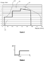
figure 4 représente une courbe d'efficacité de la réduction catalytique sélective (SCR - Selective Catalytic Reduction - en anglais) en fonction de la température ; - la
figure 5 représente un organigramme des étapes du procédé de contrôle de qualité, selon un mode de réalisation particulier de l'invention.
- the
figure 1 represents a first example of a control system; - the
figure 2 represents a second example of a control system; - the
figure 3 represents regulated and maximum operating curves of the motor vehicle; - the
figure 4 represents a curve of efficiency of the selective catalytic reduction ( SCR - Selective Catalytic Reduction - in English) as a function of the temperature; - the
figure 5 represents a flowchart of the steps of the quality control method, according to a particular embodiment of the invention.
Le système de contrôle de l'invention permet de contrôler la qualité d'un agent réducteur d'oxydes d'azote pour gaz d'échappement, injecté dans une ligne d'échappement d'un véhicule automobile, par exemple un véhicule équipé d'un moteur diesel.The control system of the invention makes it possible to control the quality of a reducing agent for nitrogen oxides for exhaust gas, injected into an exhaust line of a motor vehicle, for example a vehicle equipped with a diesel engine.
Dans l'exemple particulier décrit, l'agent réducteur est destiné à transformer les oxydes d'azote, ou NOx, qui sont l'un des constituant des gaz d'échappement, en azote N2 et en vapeur d'eau. Il contient ici de l'urée. Par exemple, il peut s'agir du produit distribué sous la marque commerciale AdBlue©, qui est constitué d'une solution aqueuse d'urée à 32,5%.In the particular example described, the reducing agent is intended to convert oxides of nitrogen, or NO x , which is one of the components of the exhaust gas, N 2 nitrogen and water vapor. It contains urea here. For example, it may be the product distributed under the trademark AdBlue®, which consists of a 32.5% aqueous solution of urea.
En référence à la
- un réservoir d'agent réducteur 1 ;
- un injecteur d'agent réducteur 2 ;
- une ligne d'échappement 3 d'un véhicule automobile (non représenté) équipé d'un moteur (non représenté) qui est ici du type suralimenté, c'est-à-dire associé à
un turbocompresseur 20 comportant un compresseur 21 et uneturbine 22 représentés sur lafigure 1 ; - un dispositif de traitement 4 des émissions polluantes du moteur ;
- un dispositif SCR de réduction catalytique sélective 5 ;
- une sonde à NOx 6 ;
et un calculateur 7 du moteur.
- a reservoir of reducing
agent 1; - a reducing
agent injector 2; - an
exhaust line 3 of a motor vehicle (not shown) equipped with a motor (not shown) which is here supercharged type, that is to say associated with aturbocharger 20 having acompressor 21 and aturbine 22 represented on thefigure 1 ; - a
device 4 for treating the polluting emissions of the engine; - an SCR selective
catalytic reduction device 5; - an
NO x 6 probe; - and a
calculator 7 of the engine.
Le réservoir 1 contient l'agent réducteur, ici de l'AdBlue©. Il peut être rempli par un utilisateur du véhicule ou par un garagiste.The
La ligne d'échappement 3 comprend un ensemble de tuyaux reliant le moteur à une sortie de pot d'échappement par laquelle les gaz d'échappement traités sont destinés à être évacués vers l'extérieur du véhicule.The
Par convention, le terme « aval » désigne le côté vers lequel les gaz d'échappement s'écoulent et le terme « amont » le côté en provenance duquel les gaz d'échappement s'écoulent.By convention, the term "downstream" refers to the side to which the exhaust flows and the term "upstream" the side from which the exhaust flows.
Dans l'exemple particulier décrit ici, la ligne d'échappement 3 comprend :
- un premier tuyau 30 de liaison entre
la turbine 22 et le dispositif de traitement 4 ; - le dispositif de traitement 4 ;
- un deuxième tuyau 31 de liaison entre le dispositif de traitement 4 et le dispositif
SCR 5; le dispositif SCR 5 ;un tuyau d'échappement 32.
- a first connecting
pipe 30 between theturbine 22 and thetreatment device 4; - the
treatment device 4; - a second connecting pipe 31 between the
processing device 4 and theSCR device 5; - the
SCR device 5; - an
exhaust pipe 32.
Comme représenté sur la
Le moteur et le pot d'échappement (non représentés) sont respectivement situés en amont et en aval de cette ligne d'échappement 3.The engine and the muffler (not shown) are respectively located upstream and downstream of this
La ligne d'échappement 3 est en outre équipée d'un tuyau 33 de dérivation des gaz d'échappement du moteur, dit tuyau EGR 33 (de l'acronyme anglais : Exhaust Gas Recycling). De manière connue, ce tuyau EGR 33 permet de prélever une partie des gaz d'échappement sur la ligne d'échappement 3 du moteur, en un point de jonction 34 situé sur le deuxième tuyau de liaison 31, et de les recycler à l'admission du moteur, plus précisément à l'entrée du compresseur 21. La proportion de gaz d'échappement ainsi recyclés à l'admission peut être dosée par une vanne 35, dite vanne EGR 35, montée sur le tuyau EGR 33.The
De manière connue, le dispositif de traitement 4 comprend par exemple un catalyseur d'oxydation, qui permet de traiter les hydrocarbures imbrûlés (HC, CO) et/ou un filtre à particules qui permet de traiter les particules de suie émises par le moteur.In a known manner, the
L'injecteur 2 est ici positionné entre le point de jonction 34 et le dispositif SCR 5. Il est relié au réservoir 1 et agencé pour injecter l'agent réducteur de NOx dans la ligne d'échappement 3, en amont du dispositif SCR 5, sous la commande du calculateur moteur 7.The
La sonde à NOx 6 est destinée à mesurer la quantité de NOx présente dans les gaz d'échappement en aval du dispositif SCR 5.The
Le calculateur moteur 7 est un système embarqué du véhicule automobile destiné à exécuter différentes fonctions relatives au moteur En particulier, il a pour fonction de contrôler la qualité de l'agent réducteur injecté dans la ligne d'échappement 3. Le calculateur 7 comprend un processeur et un module logiciel destiné au contrôle de la qualité de l'agent réducteur injecté. Le module logiciel comporte des instructions logicielles pour commander l'exécution des étapes du procédé décrit ci-après, lorsqu'il est exécuté par le processeur. Le calculateur 7 a également pour rôle de commander le fonctionnement des différents éléments du système de contrôle de qualité.The
Le système de contrôle comprend également un capteur de régime moteur et des moyens de détermination de la charge du moteur, connectés au calculateur 7. Le régime moteur mesuré est exprimé en tour/minute. La charge déterminée est soit un couple moteur exprimé en Nm (Newton mètre), soit une PME (Pression Moyenne Effective) exprimée en bar.The control system also comprises an engine speed sensor and means for determining the engine load, connected to the
Enfin, le système de contrôle comporte un voyant d'alerte 8, connecté au calculateur 7, destiné à être allumé en cas de détection d'un agent réducteur de mauvaise qualité dans le réservoir 1.Finally, the control system comprises an
Sur la
Ici, le dispositif SCR 5 est implanté juste derrière le dispositif de traitement 4, en amont de celui-ci. En d'autres termes, il n'est pas séparé du dispositif 4 par un deuxième tuyau de liaison 31 comme c'est le cas représenté sur la
Le nez de l'injecteur 2 débouche directement dans le dispositif SCR 5. En d'autres termes, en fonctionnement, l'agent réducteur est injecté dans le dispositif SCR 5 et non pas en amont de celui-ci dans le deuxième tuyau de liaison 31 de la
La sonde à NOx 6 est positionnée sur le tuyau d'échappement 32, c'est-à-dire en aval du dispositif SCR 5, en amont du point de jonction 34 qui est également situé sur le tuyau d'échappement 32.The
On va maintenant décrire, en référence à la
Dans le mode de réalisation particulier décrit ici, l'agent réducteur est un agent de réduction catalytique sélective contenant de l'urée, par exemple de l'AdBlue© et destiné à transformer les NOx en azote N2 et en eau.In the particular embodiment described herein, the reducing agent is a selective catalytic reduction agent containing urea, for example AdBlue®, for converting NO x to nitrogen N 2 and water.
Sur la
- une première courbe C1 de fonctionnement réglementé;
- une deuxième courbe C2 de fonctionnement maximal.
- a first curve C1 of regulated operation;
- a second curve C2 of maximum operation.
On note « Z1 » la zone intérieure délimitée par la courbe C1 et l'axe des abscisses et « Z2 » la zone comprise entre la première courbe C1 et la courbe C2. La zone Z1 correspond à une zone réglementée, dans laquelle le fonctionnement du véhicule est contraint par des réglementations anti-pollution, notamment de rejet de NOx. La zone Z2 est une zone non réglementée.We denote "Z1" the inner area delimited by the curve C1 and the abscissa axis and "Z2" the area between the first curve C1 and the curve C2. Zone Z1 corresponds to a restricted zone, in which the operation of the vehicle is constrained by anti-pollution regulations, in particular of NO x discharge. Zone Z2 is an unregulated area.
Chaque point contenu dans l'une des zones Z1 et Z2 correspond à un point de fonctionnement du moteur du véhicule, défini par un régime moteur et une charge moteur.Each point contained in one of the zones Z1 and Z2 corresponds to a point of operation of the engine of the vehicle, defined by an engine speed and an engine load.
Lors d'une étape préalable S0 de configuration, on effectue une série de mesures étalon de variations de NOx évacués en sortie de ligne d'échappement 3, en réponse à l'injection d'une quantité déterminée d'agent réducteur dans la ligne d'échappement du véhicule automobile. Chaque mesure étalon est indexée par l'indice i, avec i= 1, 2, ..., N, N étant le nombre total de mesures étalon réalisées. On note Δ(NOx ) ETA
Lors d'une première étape S1, le moteur du véhicule est démarré.In a first step S1, the vehicle engine is started.
Lors d'une deuxième étape S2, le capteur de régime et les moyens de détermination de la charge moteur, déterminent, à un instant tj, avec j valant initialement 1, le nombre de tours par minute du moteur, représentant le régime moteur, et la PME ou le couple du moteur, représentant la charge moteur. Le couple de valeurs régime / charge déterminé à l'instant tj est transmis au calculateur 7. La deuxième étapeS2 est suivie d'une troisième étape de test S3.At a second step S2, the engine speed sensor and means for determining the engine load, determine, at a time t j, with j equal to 1 initially, the number of revolutions per minute of the engine, representing engine speed, and the MSY or engine torque, representing the engine load. The pair of speed / load values determined at the instant t j is transmitted to the
Lors de l'étape de test S3, le calculateur 7 détecte si le couple de valeurs régime / charge déterminé à l'instant tj correspond à un point de fonctionnement de référence PFETA
Si le test S3 est négatif, le procédé revient à la deuxième étape S2, l'indice j étant incrémenté de 1, et de nouvelles valeurs de régime moteur et de charge moteur sont déterminées à l'instant tj+1.If the test S3 is negative, the process returns to the second step S2, the index j being incremented by 1, and new values of engine speed and engine load are determined at time t j + 1 .
Si le test S3 est positif, autrement dit si le couple régime / charge moteur mesuré correspond à un point de fonctionnement de référence PFETA
Lors d'une quatrième étape S4, sur commande du calculateur 7, l'injection d'agent réducteur du réservoir 1 est momentanément arrêtée pendant une durée prédéterminée. L'arrêt momentané d'injection d'agent réducteur permet ensuite de mesurer la quantité E0 de NOx évacuée par la ligne d'échappement 3 sans réduction par cet agent.During a fourth step S4, on command of the
Puis, lors d'une cinquième étape S5, la quantité E0 de NOx évacuée en fin de ligne d'échappement 3, suite à l'arrêt d'injection d'agent réducteur, est mesurée à l'aide de la sonde 6. La valeur mesurée E0 est transmise au calculateur 7.Then, during a fifth step S5, the quantity E 0 of NO x evacuated at the end of the
Le procédé passe ensuite à une sixième étape S6 lors de laquelle, sur commande du calculateur 7, l'injecteur 2 injecte dans la ligne d'échappement 3, en amont du dispositif SCR 5, une quantité prédéterminée Qi d'agent réducteur. La quantité d'agent Qi injectée est la quantité préenregistrée en mémoire, correspondant au point de fonctionnement de référence PFETA
Puis, lors d'une septième étape S7, la sonde 6 mesure la quantité E1 de NOx évacuée en réponse à l'injection de l'agent réducteur lors de l'étape S6. La valeur mesurée E1 est transmise au calculateur 7.Then, during a seventh step S7, the
Lors d'une étape S8, le calculateur 7 mesure la variation de NOx évacués en réponse à l'injection d'agent réducteur, notée Δ(NOx ) MES , en soustrayant la valeur E1 à la valeur Eo, selon l'équation : ![]()
![]()
On mesure ainsi la diminution de NOx évacués en réponse à l'injection d'agent réducteur.In this way, the decrease of NO x discharged in response to the injection of reducing agent is measured.
Lors des neuvième et dixième étapes S9 et S10, la valeur mesurée Δ(NOx ) MES de variation de NOx évacués en réponse à l'injection d'agent réducteur est comparée à une valeur de variation attendue, fonction de la valeur de variation étalon Δ(NOx ) ETA![]()
- K est un facteur correctif de vieillissement du dispositif
SCR 5. Ce facteur K est une valeur inférieure ou égale à 1 et est une fonction linéaire du kilométrage du véhicule ou de l'intégrale des tours moteur depuis l'état neuf ; - EFF(T) est un coefficient d'efficacité du dispositif
SCR 5 en fonction de la température de fonctionnement. Lafigure 4 représente une courbe de l'efficacité EFF (représentée en ordonnées) en fonction de la température de fonctionnement T (représentée en abscisses). Comme cela apparaît sur cettefigure 4 , le coefficient d'efficacité EFF(T) est nul lorsque la température de fonctionnement T est inférieure à une valeur seuil Tseuil, etvaut 1 lorsque la température de fonctionnement est supérieure à la valeur seuil Tseuil ; -

- K is an aging corrective factor of the
SCR device 5. This K factor is a value less than or equal to 1 and is a linear function of the vehicle mileage or the integral of the engine revs since the new condition; - EFF (T) is a coefficient of efficiency of the
SCR device 5 as a function of the operating temperature. Thefigure 4 represents a curve of the efficiency EFF (represented on the ordinate) as a function of the operating temperature T (represented on the abscissa). As it appears on thisfigure 4 the efficiency coefficient EFF (T) is zero when the operating temperature T is lower than a threshold value T threshold , and is 1 when the operating temperature is greater than the threshold value T threshold ; -
Ainsi, le calculateur 7 soustrait la valeur de variation de NOx attendue (c'est-à-dire la valeur étalon corrigée par le facteur de vieillissement et par le coefficient d'efficacité), soit ![]()
![]()
On pourrait toutefois envisager de calculer une simple soustraction entre la valeur Δ(NOx ) MES de variation de NOx mesurée et la valeur ![]()
![]()
Lors de la dixième étape de test S10, on compare le résultat obtenu à l'étape S9, soit DELTA_ΔNOx , à un seuil de différence prédéfini, noté S_ΔNOx. During the tenth test step S10, comparing the result obtained in step S9, DELTA_ Δ NO x , to a predefined difference threshold, denoted S_ Δ NO x .
Si la différence DELTA_ΔNOx entre variation mesurée et variation étalon est inférieure au seuil S_ΔNOx , alors le calculateur 7 détecte que la qualité de l'agent réducteur est bonne et le procédé revient à la deuxième étape S2. Le voyant d'alerte 8 n'est pas allumé. Le procédé retourne alors à la deuxième étape S2.If the difference Δ DELTA_ NOx measured between variation and variation standard is below the threshold Δ S_ NO x, then the
Si la différence DELTA_ΔNOx entre variation mesurée et variation étalon est supérieure au seuil S_ΔNOx , alors le calculateur 7 détecte que la qualité de l'agent réducteur est mauvaise et, lors d'une onzième étape S11, commande l'allumage du voyant d'alerte 8.If the difference DELTA_ Δ NO x between the measured variation and the standard variation is greater than the threshold S_ Δ NO x , then the
Ainsi, le procédé compare la valeur Δ(NOx ) MES de variation de NOx mesurée et la valeur de variation de NOx étalon, corrigée par le facteur de vieillissement et par le coefficient d'efficacité. Cette valeur de variation étalon corrigée correspond à une valeur de variation attendue.Thus, the method compares the Δ ( NO x ) MES measured NO x variation value and the standard NO x variation value, corrected by the aging factor and the efficiency coefficient. This corrected standard variation value corresponds to an expected variation value.
Dans la description qui précède, on injecte une quantité prédéterminée d'agent réducteur sur détection d'un point de fonctionnement située dans la zone Z2. En variante, on pourrait injecter une quantité déterminé, dite « supplémentaire », d'agent réducteur en un point de fonctionnement du moteur pour lequel une quantité d'agent réducteur prédéfinie, dite « de base », est déjà injectée. Dans ce cas, on comparerait la variation de NOx en sortie du dispositif SCR 5 due à ce surplus d'agent réducteur à une variation étalon de NOx préenregistrée (préalablement mesurée après injection de la quantité de base d'agent réducteur).In the foregoing description, a predetermined amount of reducing agent is injected upon detection of an operating point located in zone Z2. Alternatively, one could inject a specific amount, called "Additional" reducing agent at an operating point of the engine for which a quantity of predefined reducing agent, called "base", is already injected. In this case, the variation of NO x at the output of the
Claims (7)
- Method for checking the quality of a reducing agent for the selective catalytic reduction of nitrogen oxides, which agent is injected into an exhaust line (3) of a motor vehicle, comprising the following steps:- injecting (S6) a determined quantity of the reducing agent into the exhaust line (3);- measuring (S7 - S8) a variation in the quantity of nitrogen oxides released in response to the injection;- comparing the measured variation against an expected variation (S9 - S10);characterized in that there is, during operation of the motor vehicle, a step (S3) of detecting a predefined operating point of the motor vehicle from among a collection of pre-recorded operating points each associated in memory with a value for the standard variation in nitrogen oxides in response to an injection of a determined quantity of reducing agent, an expected variation value being determined from the standard variation value associated with the operating point detected, and in that said step (S6) of injecting a determined quantity of reducing agent is triggered upon detection (S2 - S3) of the predefined operating point of the motor vehicle and in that the said method comprises a step of subtracting the expected variation value from the measured variation value, a step of comparing the result of the subtraction, in terms of absolute value, against a predefined difference threshold and detecting that the quality of the reducing agent is good if the said result of the subtraction is below the threshold or poor if the said result of the subtraction is above the threshold.
- Method according to Claim 1, characterized in that the said operating point belongs to a motor vehicle operating zone that does not have regulatory constraints imposed upon it.
- Method according to one of Claims 1 and 2, characterized in that step (S6) of injecting a determined quantity of the reducing agent is preceded by a step (S4) of stopping the injection of the reducing agent and by a step (S5) of measuring the quantity of nitrogen oxides released in response to the stopping of the injecting of the reducing agent.
- Method according to one of Claims 1 to 3, characterized in that the expected variation is determined (S9) by correcting the pre-recorded standard variation using an ageing factor.
- Method according to one of Claims 1 to 4, characterized in that the expected variation is determined (S9) by correcting the pre-recorded standard variation using an effectiveness co-efficient dependent on the operating temperature.
- System for checking the quality of a reducing agent for the catalytic reduction of nitrogen oxides, injected into an exhaust line of a motor vehicle, comprising:- an injection device (2) for injecting the reducing agent into the exhaust line;- a measurement device (6) for measuring a quantity of nitrogen oxides released downstream of a catalytic reduction;- a control module (7) designed to command an injection of a determined quantity of the reducing agent, to calculate a variation in the quantity of nitrogen oxides released downstream of the catalytic reduction in response to the injection, from measured values and compare the measured variation against a pre-recorded expected variation;characterized in that the control module is designed to, during operation of the motor vehicle, detect a predefined operating point of the motor vehicle from among a collection of pre-recorded operating points each associated in memory with a value for the standard variation in nitrogen oxides in response to an injection of a determined quantity of reducing agent, in order to determine an expected variation value from the standard variation value associated with the operating point detected so as to trigger injection of a quantity of reducing agent into the exhaust line upon detection (S2 - S3) of the predefined operating point of the motor vehicle and to subtract the expected variation value from the measured variation value to compare the result of the subtraction, in terms of absolute value, against a predefined difference threshold and to detect that the quality of the reducing agent is good if the said result of the subtraction is below the threshold or poor if the said result of the subtraction is above the threshold.
- Software module for a system for checking the quality of a reducing agent for the catalytic reduction of nitrogen oxides injected into an exhaust line of a motor vehicle, comprising software instructions for:- during motor vehicle operation, detecting a predefined operating point of the motor vehicle from among a collection of pre-recorded operating points each associated in memory with a value for the standard variation of nitrogen oxides in response to an injection of a determined quantity of reducing agent,- determining an expected variation value from the standard variation value associated with the operating point detected,- commanding an injection of a determined quantity of the reducing agent into the exhaust line upon detection of the predefined operating point of the motor vehicle- calculating a value for the measured variation in the quantity of nitrogen oxides released downstream of a catalytic reduction in response to the injection, from measured values,- subtracting the expected variation value from the measured variation value,- comparing the result of the subtraction, in terms of absolute value, against a predefined difference threshold; and- detecting that the quality of the reducing agent is good if the said result of the subtraction is below the threshold or poor if the said result of the subtraction is above the threshold,when the said software module is executed by a processor.
Applications Claiming Priority (1)
| Application Number | Priority Date | Filing Date | Title |
|---|---|---|---|
| FR1354836A FR3006371B1 (en) | 2013-05-28 | 2013-05-28 | METHOD AND SYSTEM FOR MONITORING THE QUALITY OF A SELECTIVE CATALYTIC REDUCTION AGENT OF NITROGEN OXIDES INJECTED IN AN EXHAUST LINE OF A MOTOR VEHICLE |
Publications (2)
| Publication Number | Publication Date |
|---|---|
| EP2808510A1 EP2808510A1 (en) | 2014-12-03 |
| EP2808510B1 true EP2808510B1 (en) | 2018-07-04 |
Family
ID=49054744
Family Applications (1)
| Application Number | Title | Priority Date | Filing Date |
|---|---|---|---|
| EP14305762.8A Active EP2808510B1 (en) | 2013-05-28 | 2014-05-23 | Method and system for controlling the quality of an agent for selective catalytic reduction of nitrogen oxides, injected into an exhaust line of a motor vehicle |
Country Status (2)
| Country | Link |
|---|---|
| EP (1) | EP2808510B1 (en) |
| FR (1) | FR3006371B1 (en) |
Families Citing this family (2)
| Publication number | Priority date | Publication date | Assignee | Title |
|---|---|---|---|---|
| CN104857853A (en) * | 2015-05-27 | 2015-08-26 | 山东应天节能环保科技有限公司 | Conveying device for conveying powdery catalyst according to sulfur and nitrate content in flue gas |
| CN109339916B (en) * | 2018-09-30 | 2020-09-01 | 广西玉柴机器股份有限公司 | Control method and system in SCR downstream NOx closed-loop process |
Family Cites Families (4)
| Publication number | Priority date | Publication date | Assignee | Title |
|---|---|---|---|---|
| CN100587235C (en) * | 2005-09-29 | 2010-02-03 | 沃尔沃拉斯特瓦格纳公司 | Diagnosis method for exhaustion post-processing system |
| FR2907160B1 (en) * | 2006-10-13 | 2008-12-26 | Peugeot Citroen Automobiles Sa | UREA QUANTITY CLOSED LOOP CONTROL METHOD FOR NITROGEN OXIDE PROCESSING SYSTEM |
| JP4661814B2 (en) * | 2007-03-29 | 2011-03-30 | トヨタ自動車株式会社 | Exhaust gas purification device for internal combustion engine |
| US7832200B2 (en) * | 2008-04-23 | 2010-11-16 | Caterpillar Inc | Exhaust system implementing feedforward and feedback control |
-
2013
- 2013-05-28 FR FR1354836A patent/FR3006371B1/en not_active Expired - Fee Related
-
2014
- 2014-05-23 EP EP14305762.8A patent/EP2808510B1/en active Active
Non-Patent Citations (1)
| Title |
|---|
| None * |
Also Published As
| Publication number | Publication date |
|---|---|
| FR3006371B1 (en) | 2017-04-28 |
| FR3006371A1 (en) | 2014-12-05 |
| EP2808510A1 (en) | 2014-12-03 |
Similar Documents
| Publication | Publication Date | Title |
|---|---|---|
| EP2274506B1 (en) | Method for correcting nitrogen oxide emission models | |
| EP3014082B1 (en) | System and method for diagnosing the selective catalytic reduction system of a motor vehicle | |
| FR3029973A1 (en) | METHOD FOR MONITORING AN OXIDATION CATALYSIS DEVICE | |
| EP1864007B1 (en) | Method and device for monitoring a particle filter in the exhaust line of an internal combustion engine | |
| FR2928691A1 (en) | METHOD AND DEVICE FOR MONITORING AN AIR SUPPLY SYSTEM OF AN INTERNAL COMBUSTION ENGINE | |
| US9068495B2 (en) | Oxidation catalyst/hydrocarbon injector testing system | |
| EP2932059B1 (en) | Method for diagnosing a nitrogen oxide trap | |
| EP2808510B1 (en) | Method and system for controlling the quality of an agent for selective catalytic reduction of nitrogen oxides, injected into an exhaust line of a motor vehicle | |
| EP3234326B1 (en) | Diagnostic method of an exhaust gas recirculation system of an automobile engine | |
| EP3387230B1 (en) | Method for diagnosing a catalyst for selective reduction of nitrogen oxides of an engine and associated device | |
| EP1739291B1 (en) | System for regenerating purification means which are integrated in an exhaust line of an engine of an automobile | |
| FR3069574B1 (en) | METHOD FOR ADAPTING A QUANTITY OF REDUCING AGENT FOR GAS NITROGEN OXIDE DEPOLLUTION IN AN ENGINE EXHAUST LINE | |
| EP2802760B1 (en) | Optimized management of an scr catalyst by means of the periodic regeneration of a particle filter | |
| FR3062418B1 (en) | METHOD FOR CONTROLLING THE EMISSIONS OF NITROGEN OXIDES TO THE EXHAUST OF AN INTERNAL COMBUSTION ENGINE | |
| EP2193261B1 (en) | Method and system for managing an exhaust gas processing module | |
| EP3359787B1 (en) | Method for diagnosing a catalyst for selective reduction of nitrogen oxides | |
| FR2948979A1 (en) | Nitrogen oxide sensor diagnosing and controlling method for e.g. diesel engine of motor vehicle, involves calibrating zero value of nitrogen oxide sensor during phase in which engine functions along rich combustion mode | |
| EP2466087B1 (en) | Diagnostic procedure of a SCR system for a vehicle and corresponding vehicle | |
| FR2951501B1 (en) | METHOD FOR MANAGING AN EXHAUST GAS POST-TREATMENT DEVICE AND CONTROL AND / OR REGULATION INSTALLATION FOR ITS IMPLEMENTATION | |
| EP2491232B1 (en) | Method for detecting mechanical failure in a nitrogen oxide treatment system | |
| FR2914355A1 (en) | METHOD AND DEVICE FOR DIAGNOSING AN EXHAUST GAS CLEANING SYSTEM | |
| EP3536920A1 (en) | Method for correcting an estimate of an amount of nitrogen oxides according to a humidity rate | |
| FR2953559A1 (en) | SYSTEM AND METHOD FOR ESTIMATING THE MASS OF PARTICLES STORED IN A PARTICLE FILTER OF A MOTOR VEHICLE | |
| EP3043041B1 (en) | Method for treating nitrogen oxides emitted from an internal combustion engine | |
| EP3056703B1 (en) | Method and system for reducing nitrogen oxides emitted from an internal combustion engine |
Legal Events
| Date | Code | Title | Description |
|---|---|---|---|
| PUAI | Public reference made under article 153(3) epc to a published international application that has entered the european phase |
Free format text: ORIGINAL CODE: 0009012 |
|
| 17P | Request for examination filed |
Effective date: 20140523 |
|
| AK | Designated contracting states |
Kind code of ref document: A1 Designated state(s): AL AT BE BG CH CY CZ DE DK EE ES FI FR GB GR HR HU IE IS IT LI LT LU LV MC MK MT NL NO PL PT RO RS SE SI SK SM TR |
|
| AX | Request for extension of the european patent |
Extension state: BA ME |
|
| R17P | Request for examination filed (corrected) |
Effective date: 20150324 |
|
| RBV | Designated contracting states (corrected) |
Designated state(s): AL AT BE BG CH CY CZ DE DK EE ES FI FR GB GR HR HU IE IS IT LI LT LU LV MC MK MT NL NO PL PT RO RS SE SI SK SM TR |
|
| 17Q | First examination report despatched |
Effective date: 20151027 |
|
| RIC1 | Information provided on ipc code assigned before grant |
Ipc: F01N 3/20 20060101AFI20171106BHEP Ipc: F01N 3/021 20060101ALN20171106BHEP Ipc: F01N 3/10 20060101ALN20171106BHEP Ipc: B01D 53/94 20060101ALI20171106BHEP Ipc: F01N 5/04 20060101ALN20171106BHEP Ipc: F01N 13/02 20100101ALN20171106BHEP |
|
| GRAP | Despatch of communication of intention to grant a patent |
Free format text: ORIGINAL CODE: EPIDOSNIGR1 |
|
| STAA | Information on the status of an ep patent application or granted ep patent |
Free format text: STATUS: GRANT OF PATENT IS INTENDED |
|
| INTG | Intention to grant announced |
Effective date: 20180122 |
|
| GRAS | Grant fee paid |
Free format text: ORIGINAL CODE: EPIDOSNIGR3 |
|
| GRAA | (expected) grant |
Free format text: ORIGINAL CODE: 0009210 |
|
| STAA | Information on the status of an ep patent application or granted ep patent |
Free format text: STATUS: THE PATENT HAS BEEN GRANTED |
|
| AK | Designated contracting states |
Kind code of ref document: B1 Designated state(s): AL AT BE BG CH CY CZ DE DK EE ES FI FR GB GR HR HU IE IS IT LI LT LU LV MC MK MT NL NO PL PT RO RS SE SI SK SM TR |
|
| REG | Reference to a national code |
Ref country code: GB Ref legal event code: FG4D Free format text: NOT ENGLISH |
|
| REG | Reference to a national code |
Ref country code: CH Ref legal event code: EP |
|
| REG | Reference to a national code |
Ref country code: AT Ref legal event code: REF Ref document number: 1014746 Country of ref document: AT Kind code of ref document: T Effective date: 20180715 |
|
| REG | Reference to a national code |
Ref country code: IE Ref legal event code: FG4D Free format text: LANGUAGE OF EP DOCUMENT: FRENCH |
|
| REG | Reference to a national code |
Ref country code: DE Ref legal event code: R096 Ref document number: 602014027804 Country of ref document: DE |
|
| REG | Reference to a national code |
Ref country code: NL Ref legal event code: MP Effective date: 20180704 |
|
| REG | Reference to a national code |
Ref country code: LT Ref legal event code: MG4D |
|
| REG | Reference to a national code |
Ref country code: AT Ref legal event code: MK05 Ref document number: 1014746 Country of ref document: AT Kind code of ref document: T Effective date: 20180704 |
|
| PG25 | Lapsed in a contracting state [announced via postgrant information from national office to epo] |
Ref country code: NL Free format text: LAPSE BECAUSE OF FAILURE TO SUBMIT A TRANSLATION OF THE DESCRIPTION OR TO PAY THE FEE WITHIN THE PRESCRIBED TIME-LIMIT Effective date: 20180704 |
|
| PG25 | Lapsed in a contracting state [announced via postgrant information from national office to epo] |
Ref country code: GR Free format text: LAPSE BECAUSE OF FAILURE TO SUBMIT A TRANSLATION OF THE DESCRIPTION OR TO PAY THE FEE WITHIN THE PRESCRIBED TIME-LIMIT Effective date: 20181005 Ref country code: BG Free format text: LAPSE BECAUSE OF FAILURE TO SUBMIT A TRANSLATION OF THE DESCRIPTION OR TO PAY THE FEE WITHIN THE PRESCRIBED TIME-LIMIT Effective date: 20181004 Ref country code: SE Free format text: LAPSE BECAUSE OF FAILURE TO SUBMIT A TRANSLATION OF THE DESCRIPTION OR TO PAY THE FEE WITHIN THE PRESCRIBED TIME-LIMIT Effective date: 20180704 Ref country code: LT Free format text: LAPSE BECAUSE OF FAILURE TO SUBMIT A TRANSLATION OF THE DESCRIPTION OR TO PAY THE FEE WITHIN THE PRESCRIBED TIME-LIMIT Effective date: 20180704 Ref country code: PL Free format text: LAPSE BECAUSE OF FAILURE TO SUBMIT A TRANSLATION OF THE DESCRIPTION OR TO PAY THE FEE WITHIN THE PRESCRIBED TIME-LIMIT Effective date: 20180704 Ref country code: FI Free format text: LAPSE BECAUSE OF FAILURE TO SUBMIT A TRANSLATION OF THE DESCRIPTION OR TO PAY THE FEE WITHIN THE PRESCRIBED TIME-LIMIT Effective date: 20180704 Ref country code: CZ Free format text: LAPSE BECAUSE OF FAILURE TO SUBMIT A TRANSLATION OF THE DESCRIPTION OR TO PAY THE FEE WITHIN THE PRESCRIBED TIME-LIMIT Effective date: 20180704 Ref country code: RS Free format text: LAPSE BECAUSE OF FAILURE TO SUBMIT A TRANSLATION OF THE DESCRIPTION OR TO PAY THE FEE WITHIN THE PRESCRIBED TIME-LIMIT Effective date: 20180704 Ref country code: AT Free format text: LAPSE BECAUSE OF FAILURE TO SUBMIT A TRANSLATION OF THE DESCRIPTION OR TO PAY THE FEE WITHIN THE PRESCRIBED TIME-LIMIT Effective date: 20180704 Ref country code: NO Free format text: LAPSE BECAUSE OF FAILURE TO SUBMIT A TRANSLATION OF THE DESCRIPTION OR TO PAY THE FEE WITHIN THE PRESCRIBED TIME-LIMIT Effective date: 20181004 Ref country code: IS Free format text: LAPSE BECAUSE OF FAILURE TO SUBMIT A TRANSLATION OF THE DESCRIPTION OR TO PAY THE FEE WITHIN THE PRESCRIBED TIME-LIMIT Effective date: 20181104 |
|
| PG25 | Lapsed in a contracting state [announced via postgrant information from national office to epo] |
Ref country code: AL Free format text: LAPSE BECAUSE OF FAILURE TO SUBMIT A TRANSLATION OF THE DESCRIPTION OR TO PAY THE FEE WITHIN THE PRESCRIBED TIME-LIMIT Effective date: 20180704 Ref country code: ES Free format text: LAPSE BECAUSE OF FAILURE TO SUBMIT A TRANSLATION OF THE DESCRIPTION OR TO PAY THE FEE WITHIN THE PRESCRIBED TIME-LIMIT Effective date: 20180704 Ref country code: HR Free format text: LAPSE BECAUSE OF FAILURE TO SUBMIT A TRANSLATION OF THE DESCRIPTION OR TO PAY THE FEE WITHIN THE PRESCRIBED TIME-LIMIT Effective date: 20180704 Ref country code: LV Free format text: LAPSE BECAUSE OF FAILURE TO SUBMIT A TRANSLATION OF THE DESCRIPTION OR TO PAY THE FEE WITHIN THE PRESCRIBED TIME-LIMIT Effective date: 20180704 |
|
| REG | Reference to a national code |
Ref country code: DE Ref legal event code: R097 Ref document number: 602014027804 Country of ref document: DE |
|
| PG25 | Lapsed in a contracting state [announced via postgrant information from national office to epo] |
Ref country code: RO Free format text: LAPSE BECAUSE OF FAILURE TO SUBMIT A TRANSLATION OF THE DESCRIPTION OR TO PAY THE FEE WITHIN THE PRESCRIBED TIME-LIMIT Effective date: 20180704 Ref country code: IT Free format text: LAPSE BECAUSE OF FAILURE TO SUBMIT A TRANSLATION OF THE DESCRIPTION OR TO PAY THE FEE WITHIN THE PRESCRIBED TIME-LIMIT Effective date: 20180704 Ref country code: EE Free format text: LAPSE BECAUSE OF FAILURE TO SUBMIT A TRANSLATION OF THE DESCRIPTION OR TO PAY THE FEE WITHIN THE PRESCRIBED TIME-LIMIT Effective date: 20180704 |
|
| PLBE | No opposition filed within time limit |
Free format text: ORIGINAL CODE: 0009261 |
|
| STAA | Information on the status of an ep patent application or granted ep patent |
Free format text: STATUS: NO OPPOSITION FILED WITHIN TIME LIMIT |
|
| PG25 | Lapsed in a contracting state [announced via postgrant information from national office to epo] |
Ref country code: SK Free format text: LAPSE BECAUSE OF FAILURE TO SUBMIT A TRANSLATION OF THE DESCRIPTION OR TO PAY THE FEE WITHIN THE PRESCRIBED TIME-LIMIT Effective date: 20180704 Ref country code: DK Free format text: LAPSE BECAUSE OF FAILURE TO SUBMIT A TRANSLATION OF THE DESCRIPTION OR TO PAY THE FEE WITHIN THE PRESCRIBED TIME-LIMIT Effective date: 20180704 Ref country code: SM Free format text: LAPSE BECAUSE OF FAILURE TO SUBMIT A TRANSLATION OF THE DESCRIPTION OR TO PAY THE FEE WITHIN THE PRESCRIBED TIME-LIMIT Effective date: 20180704 |
|
| 26N | No opposition filed |
Effective date: 20190405 |
|
| PG25 | Lapsed in a contracting state [announced via postgrant information from national office to epo] |
Ref country code: SI Free format text: LAPSE BECAUSE OF FAILURE TO SUBMIT A TRANSLATION OF THE DESCRIPTION OR TO PAY THE FEE WITHIN THE PRESCRIBED TIME-LIMIT Effective date: 20180704 |
|
| REG | Reference to a national code |
Ref country code: CH Ref legal event code: PL |
|
| GBPC | Gb: european patent ceased through non-payment of renewal fee |
Effective date: 20190523 |
|
| PG25 | Lapsed in a contracting state [announced via postgrant information from national office to epo] |
Ref country code: CH Free format text: LAPSE BECAUSE OF NON-PAYMENT OF DUE FEES Effective date: 20190531 Ref country code: LI Free format text: LAPSE BECAUSE OF NON-PAYMENT OF DUE FEES Effective date: 20190531 Ref country code: MC Free format text: LAPSE BECAUSE OF FAILURE TO SUBMIT A TRANSLATION OF THE DESCRIPTION OR TO PAY THE FEE WITHIN THE PRESCRIBED TIME-LIMIT Effective date: 20180704 |
|
| REG | Reference to a national code |
Ref country code: BE Ref legal event code: MM Effective date: 20190531 |
|
| PG25 | Lapsed in a contracting state [announced via postgrant information from national office to epo] |
Ref country code: LU Free format text: LAPSE BECAUSE OF NON-PAYMENT OF DUE FEES Effective date: 20190523 |
|
| PG25 | Lapsed in a contracting state [announced via postgrant information from national office to epo] |
Ref country code: TR Free format text: LAPSE BECAUSE OF FAILURE TO SUBMIT A TRANSLATION OF THE DESCRIPTION OR TO PAY THE FEE WITHIN THE PRESCRIBED TIME-LIMIT Effective date: 20180704 |
|
| PG25 | Lapsed in a contracting state [announced via postgrant information from national office to epo] |
Ref country code: IE Free format text: LAPSE BECAUSE OF NON-PAYMENT OF DUE FEES Effective date: 20190523 Ref country code: GB Free format text: LAPSE BECAUSE OF NON-PAYMENT OF DUE FEES Effective date: 20190523 |
|
| PG25 | Lapsed in a contracting state [announced via postgrant information from national office to epo] |
Ref country code: BE Free format text: LAPSE BECAUSE OF NON-PAYMENT OF DUE FEES Effective date: 20190531 |
|
| PG25 | Lapsed in a contracting state [announced via postgrant information from national office to epo] |
Ref country code: PT Free format text: LAPSE BECAUSE OF FAILURE TO SUBMIT A TRANSLATION OF THE DESCRIPTION OR TO PAY THE FEE WITHIN THE PRESCRIBED TIME-LIMIT Effective date: 20181105 |
|
| PG25 | Lapsed in a contracting state [announced via postgrant information from national office to epo] |
Ref country code: CY Free format text: LAPSE BECAUSE OF FAILURE TO SUBMIT A TRANSLATION OF THE DESCRIPTION OR TO PAY THE FEE WITHIN THE PRESCRIBED TIME-LIMIT Effective date: 20180704 |
|
| PG25 | Lapsed in a contracting state [announced via postgrant information from national office to epo] |
Ref country code: MT Free format text: LAPSE BECAUSE OF FAILURE TO SUBMIT A TRANSLATION OF THE DESCRIPTION OR TO PAY THE FEE WITHIN THE PRESCRIBED TIME-LIMIT Effective date: 20180704 Ref country code: HU Free format text: LAPSE BECAUSE OF FAILURE TO SUBMIT A TRANSLATION OF THE DESCRIPTION OR TO PAY THE FEE WITHIN THE PRESCRIBED TIME-LIMIT; INVALID AB INITIO Effective date: 20140523 |
|
| PG25 | Lapsed in a contracting state [announced via postgrant information from national office to epo] |
Ref country code: MK Free format text: LAPSE BECAUSE OF FAILURE TO SUBMIT A TRANSLATION OF THE DESCRIPTION OR TO PAY THE FEE WITHIN THE PRESCRIBED TIME-LIMIT Effective date: 20180704 |
|
| P01 | Opt-out of the competence of the unified patent court (upc) registered |
Effective date: 20230608 |
|
| PGFP | Annual fee paid to national office [announced via postgrant information from national office to epo] |
Ref country code: FR Payment date: 20230526 Year of fee payment: 10 Ref country code: DE Payment date: 20230519 Year of fee payment: 10 |