EP2808510B1 - Qualitätskontrollverfahren und -system eines selektiven katalytischen reduktionsmittels von stickoxiden, das in die auspuffanlage eines kraftfahrzeugs eingespritzt wird - Google Patents
Qualitätskontrollverfahren und -system eines selektiven katalytischen reduktionsmittels von stickoxiden, das in die auspuffanlage eines kraftfahrzeugs eingespritzt wird Download PDFInfo
- Publication number
- EP2808510B1 EP2808510B1 EP14305762.8A EP14305762A EP2808510B1 EP 2808510 B1 EP2808510 B1 EP 2808510B1 EP 14305762 A EP14305762 A EP 14305762A EP 2808510 B1 EP2808510 B1 EP 2808510B1
- Authority
- EP
- European Patent Office
- Prior art keywords
- reducing agent
- variation
- motor vehicle
- injection
- nitrogen oxides
- Prior art date
- Legal status (The legal status is an assumption and is not a legal conclusion. Google has not performed a legal analysis and makes no representation as to the accuracy of the status listed.)
- Active
Links
Images


Classifications
-
- F—MECHANICAL ENGINEERING; LIGHTING; HEATING; WEAPONS; BLASTING
- F01—MACHINES OR ENGINES IN GENERAL; ENGINE PLANTS IN GENERAL; STEAM ENGINES
- F01N—GAS-FLOW SILENCERS OR EXHAUST APPARATUS FOR MACHINES OR ENGINES IN GENERAL; GAS-FLOW SILENCERS OR EXHAUST APPARATUS FOR INTERNAL-COMBUSTION ENGINES
- F01N3/00—Exhaust or silencing apparatus having means for purifying, rendering innocuous, or otherwise treating exhaust
- F01N3/08—Exhaust or silencing apparatus having means for purifying, rendering innocuous, or otherwise treating exhaust for rendering innocuous
- F01N3/10—Exhaust or silencing apparatus having means for purifying, rendering innocuous, or otherwise treating exhaust for rendering innocuous by thermal or catalytic conversion of noxious components of exhaust
- F01N3/18—Exhaust or silencing apparatus having means for purifying, rendering innocuous, or otherwise treating exhaust for rendering innocuous by thermal or catalytic conversion of noxious components of exhaust characterised by methods of operation; Control
- F01N3/20—Exhaust or silencing apparatus having means for purifying, rendering innocuous, or otherwise treating exhaust for rendering innocuous by thermal or catalytic conversion of noxious components of exhaust characterised by methods of operation; Control specially adapted for catalytic conversion
- F01N3/206—Adding periodically or continuously substances to exhaust gases for promoting purification, e.g. catalytic material in liquid form, NOx reducing agents
- F01N3/2066—Selective catalytic reduction [SCR]
-
- B—PERFORMING OPERATIONS; TRANSPORTING
- B01—PHYSICAL OR CHEMICAL PROCESSES OR APPARATUS IN GENERAL
- B01D—SEPARATION
- B01D53/00—Separation of gases or vapours; Recovering vapours of volatile solvents from gases; Chemical or biological purification of waste gases, e.g. engine exhaust gases, smoke, fumes, flue gases, aerosols
- B01D53/34—Chemical or biological purification of waste gases
- B01D53/92—Chemical or biological purification of waste gases of engine exhaust gases
- B01D53/94—Chemical or biological purification of waste gases of engine exhaust gases by catalytic processes
- B01D53/9495—Controlling the catalytic process
-
- F—MECHANICAL ENGINEERING; LIGHTING; HEATING; WEAPONS; BLASTING
- F01—MACHINES OR ENGINES IN GENERAL; ENGINE PLANTS IN GENERAL; STEAM ENGINES
- F01N—GAS-FLOW SILENCERS OR EXHAUST APPARATUS FOR MACHINES OR ENGINES IN GENERAL; GAS-FLOW SILENCERS OR EXHAUST APPARATUS FOR INTERNAL-COMBUSTION ENGINES
- F01N13/00—Exhaust or silencing apparatus characterised by constructional features
- F01N13/009—Exhaust or silencing apparatus characterised by constructional features having two or more separate purifying devices arranged in series
- F01N13/0097—Exhaust or silencing apparatus characterised by constructional features having two or more separate purifying devices arranged in series the purifying devices are arranged in a single housing
-
- F—MECHANICAL ENGINEERING; LIGHTING; HEATING; WEAPONS; BLASTING
- F01—MACHINES OR ENGINES IN GENERAL; ENGINE PLANTS IN GENERAL; STEAM ENGINES
- F01N—GAS-FLOW SILENCERS OR EXHAUST APPARATUS FOR MACHINES OR ENGINES IN GENERAL; GAS-FLOW SILENCERS OR EXHAUST APPARATUS FOR INTERNAL-COMBUSTION ENGINES
- F01N3/00—Exhaust or silencing apparatus having means for purifying, rendering innocuous, or otherwise treating exhaust
- F01N3/08—Exhaust or silencing apparatus having means for purifying, rendering innocuous, or otherwise treating exhaust for rendering innocuous
- F01N3/10—Exhaust or silencing apparatus having means for purifying, rendering innocuous, or otherwise treating exhaust for rendering innocuous by thermal or catalytic conversion of noxious components of exhaust
- F01N3/18—Exhaust or silencing apparatus having means for purifying, rendering innocuous, or otherwise treating exhaust for rendering innocuous by thermal or catalytic conversion of noxious components of exhaust characterised by methods of operation; Control
- F01N3/20—Exhaust or silencing apparatus having means for purifying, rendering innocuous, or otherwise treating exhaust for rendering innocuous by thermal or catalytic conversion of noxious components of exhaust characterised by methods of operation; Control specially adapted for catalytic conversion
- F01N3/206—Adding periodically or continuously substances to exhaust gases for promoting purification, e.g. catalytic material in liquid form, NOx reducing agents
- F01N3/208—Control of selective catalytic reduction [SCR], e.g. by adjusting the dosing of reducing agent
-
- F—MECHANICAL ENGINEERING; LIGHTING; HEATING; WEAPONS; BLASTING
- F01—MACHINES OR ENGINES IN GENERAL; ENGINE PLANTS IN GENERAL; STEAM ENGINES
- F01N—GAS-FLOW SILENCERS OR EXHAUST APPARATUS FOR MACHINES OR ENGINES IN GENERAL; GAS-FLOW SILENCERS OR EXHAUST APPARATUS FOR INTERNAL-COMBUSTION ENGINES
- F01N2560/00—Exhaust systems with means for detecting or measuring exhaust gas components or characteristics
- F01N2560/02—Exhaust systems with means for detecting or measuring exhaust gas components or characteristics the means being an exhaust gas sensor
- F01N2560/026—Exhaust systems with means for detecting or measuring exhaust gas components or characteristics the means being an exhaust gas sensor for measuring or detecting NOx
-
- F—MECHANICAL ENGINEERING; LIGHTING; HEATING; WEAPONS; BLASTING
- F01—MACHINES OR ENGINES IN GENERAL; ENGINE PLANTS IN GENERAL; STEAM ENGINES
- F01N—GAS-FLOW SILENCERS OR EXHAUST APPARATUS FOR MACHINES OR ENGINES IN GENERAL; GAS-FLOW SILENCERS OR EXHAUST APPARATUS FOR INTERNAL-COMBUSTION ENGINES
- F01N2610/00—Adding substances to exhaust gases
- F01N2610/02—Adding substances to exhaust gases the substance being ammonia or urea
-
- F—MECHANICAL ENGINEERING; LIGHTING; HEATING; WEAPONS; BLASTING
- F01—MACHINES OR ENGINES IN GENERAL; ENGINE PLANTS IN GENERAL; STEAM ENGINES
- F01N—GAS-FLOW SILENCERS OR EXHAUST APPARATUS FOR MACHINES OR ENGINES IN GENERAL; GAS-FLOW SILENCERS OR EXHAUST APPARATUS FOR INTERNAL-COMBUSTION ENGINES
- F01N2900/00—Details of electrical control or of the monitoring of the exhaust gas treating apparatus
- F01N2900/04—Methods of control or diagnosing
- F01N2900/0412—Methods of control or diagnosing using pre-calibrated maps, tables or charts
-
- F—MECHANICAL ENGINEERING; LIGHTING; HEATING; WEAPONS; BLASTING
- F01—MACHINES OR ENGINES IN GENERAL; ENGINE PLANTS IN GENERAL; STEAM ENGINES
- F01N—GAS-FLOW SILENCERS OR EXHAUST APPARATUS FOR MACHINES OR ENGINES IN GENERAL; GAS-FLOW SILENCERS OR EXHAUST APPARATUS FOR INTERNAL-COMBUSTION ENGINES
- F01N2900/00—Details of electrical control or of the monitoring of the exhaust gas treating apparatus
- F01N2900/06—Parameters used for exhaust control or diagnosing
- F01N2900/0601—Parameters used for exhaust control or diagnosing being estimated
-
- F—MECHANICAL ENGINEERING; LIGHTING; HEATING; WEAPONS; BLASTING
- F01—MACHINES OR ENGINES IN GENERAL; ENGINE PLANTS IN GENERAL; STEAM ENGINES
- F01N—GAS-FLOW SILENCERS OR EXHAUST APPARATUS FOR MACHINES OR ENGINES IN GENERAL; GAS-FLOW SILENCERS OR EXHAUST APPARATUS FOR INTERNAL-COMBUSTION ENGINES
- F01N2900/00—Details of electrical control or of the monitoring of the exhaust gas treating apparatus
- F01N2900/06—Parameters used for exhaust control or diagnosing
- F01N2900/14—Parameters used for exhaust control or diagnosing said parameters being related to the exhaust gas
- F01N2900/1402—Exhaust gas composition
-
- F—MECHANICAL ENGINEERING; LIGHTING; HEATING; WEAPONS; BLASTING
- F01—MACHINES OR ENGINES IN GENERAL; ENGINE PLANTS IN GENERAL; STEAM ENGINES
- F01N—GAS-FLOW SILENCERS OR EXHAUST APPARATUS FOR MACHINES OR ENGINES IN GENERAL; GAS-FLOW SILENCERS OR EXHAUST APPARATUS FOR INTERNAL-COMBUSTION ENGINES
- F01N2900/00—Details of electrical control or of the monitoring of the exhaust gas treating apparatus
- F01N2900/06—Parameters used for exhaust control or diagnosing
- F01N2900/18—Parameters used for exhaust control or diagnosing said parameters being related to the system for adding a substance into the exhaust
- F01N2900/1806—Properties of reducing agent or dosing system
- F01N2900/1818—Concentration of the reducing agent
-
- F—MECHANICAL ENGINEERING; LIGHTING; HEATING; WEAPONS; BLASTING
- F01—MACHINES OR ENGINES IN GENERAL; ENGINE PLANTS IN GENERAL; STEAM ENGINES
- F01N—GAS-FLOW SILENCERS OR EXHAUST APPARATUS FOR MACHINES OR ENGINES IN GENERAL; GAS-FLOW SILENCERS OR EXHAUST APPARATUS FOR INTERNAL-COMBUSTION ENGINES
- F01N3/00—Exhaust or silencing apparatus having means for purifying, rendering innocuous, or otherwise treating exhaust
- F01N3/02—Exhaust or silencing apparatus having means for purifying, rendering innocuous, or otherwise treating exhaust for cooling, or for removing solid constituents of, exhaust
- F01N3/021—Exhaust or silencing apparatus having means for purifying, rendering innocuous, or otherwise treating exhaust for cooling, or for removing solid constituents of, exhaust by means of filters
-
- F—MECHANICAL ENGINEERING; LIGHTING; HEATING; WEAPONS; BLASTING
- F01—MACHINES OR ENGINES IN GENERAL; ENGINE PLANTS IN GENERAL; STEAM ENGINES
- F01N—GAS-FLOW SILENCERS OR EXHAUST APPARATUS FOR MACHINES OR ENGINES IN GENERAL; GAS-FLOW SILENCERS OR EXHAUST APPARATUS FOR INTERNAL-COMBUSTION ENGINES
- F01N3/00—Exhaust or silencing apparatus having means for purifying, rendering innocuous, or otherwise treating exhaust
- F01N3/08—Exhaust or silencing apparatus having means for purifying, rendering innocuous, or otherwise treating exhaust for rendering innocuous
- F01N3/10—Exhaust or silencing apparatus having means for purifying, rendering innocuous, or otherwise treating exhaust for rendering innocuous by thermal or catalytic conversion of noxious components of exhaust
- F01N3/103—Oxidation catalysts for HC and CO only
-
- F—MECHANICAL ENGINEERING; LIGHTING; HEATING; WEAPONS; BLASTING
- F01—MACHINES OR ENGINES IN GENERAL; ENGINE PLANTS IN GENERAL; STEAM ENGINES
- F01N—GAS-FLOW SILENCERS OR EXHAUST APPARATUS FOR MACHINES OR ENGINES IN GENERAL; GAS-FLOW SILENCERS OR EXHAUST APPARATUS FOR INTERNAL-COMBUSTION ENGINES
- F01N5/00—Exhaust or silencing apparatus combined or associated with devices profiting by exhaust energy
- F01N5/04—Exhaust or silencing apparatus combined or associated with devices profiting by exhaust energy the devices using kinetic energy
-
- Y—GENERAL TAGGING OF NEW TECHNOLOGICAL DEVELOPMENTS; GENERAL TAGGING OF CROSS-SECTIONAL TECHNOLOGIES SPANNING OVER SEVERAL SECTIONS OF THE IPC; TECHNICAL SUBJECTS COVERED BY FORMER USPC CROSS-REFERENCE ART COLLECTIONS [XRACs] AND DIGESTS
- Y02—TECHNOLOGIES OR APPLICATIONS FOR MITIGATION OR ADAPTATION AGAINST CLIMATE CHANGE
- Y02A—TECHNOLOGIES FOR ADAPTATION TO CLIMATE CHANGE
- Y02A50/00—TECHNOLOGIES FOR ADAPTATION TO CLIMATE CHANGE in human health protection, e.g. against extreme weather
- Y02A50/20—Air quality improvement or preservation, e.g. vehicle emission control or emission reduction by using catalytic converters
-
- Y—GENERAL TAGGING OF NEW TECHNOLOGICAL DEVELOPMENTS; GENERAL TAGGING OF CROSS-SECTIONAL TECHNOLOGIES SPANNING OVER SEVERAL SECTIONS OF THE IPC; TECHNICAL SUBJECTS COVERED BY FORMER USPC CROSS-REFERENCE ART COLLECTIONS [XRACs] AND DIGESTS
- Y02—TECHNOLOGIES OR APPLICATIONS FOR MITIGATION OR ADAPTATION AGAINST CLIMATE CHANGE
- Y02C—CAPTURE, STORAGE, SEQUESTRATION OR DISPOSAL OF GREENHOUSE GASES [GHG]
- Y02C20/00—Capture or disposal of greenhouse gases
- Y02C20/10—Capture or disposal of greenhouse gases of nitrous oxide (N2O)
-
- Y—GENERAL TAGGING OF NEW TECHNOLOGICAL DEVELOPMENTS; GENERAL TAGGING OF CROSS-SECTIONAL TECHNOLOGIES SPANNING OVER SEVERAL SECTIONS OF THE IPC; TECHNICAL SUBJECTS COVERED BY FORMER USPC CROSS-REFERENCE ART COLLECTIONS [XRACs] AND DIGESTS
- Y02—TECHNOLOGIES OR APPLICATIONS FOR MITIGATION OR ADAPTATION AGAINST CLIMATE CHANGE
- Y02T—CLIMATE CHANGE MITIGATION TECHNOLOGIES RELATED TO TRANSPORTATION
- Y02T10/00—Road transport of goods or passengers
- Y02T10/10—Internal combustion engine [ICE] based vehicles
- Y02T10/12—Improving ICE efficiencies
Definitions
- the invention relates to a method and a system for controlling the quality of an exhaust gas cleaning agent for an engine, injected into an exhaust line of a motor vehicle, more specifically a selective catalytic reduction agent. intended to reduce the emission of nitrogen oxides from the engine.
- the SCR Selective Catalytic Reduction in English
- SCR Selective Catalytic Reduction in French
- Its principle is to implement, within a treatment device called "SCR device” a reduction that converts NO x N 2 nitrogen and water vapor. This conversion is obtained by injection into the exhaust line of the motor vehicle, a reducing agent, or reducing agent.
- This agent is for example an aqueous solution of urea.
- AdBlue® a solution of this type, distributed under the trade name AdBlue®, is known for use as a reducing agent in the selective catalytic reduction process.
- the implementation of SCR technology in a vehicle requires the installation of a reducing agent tank, a reducing agent injector, SCR device and at least one NO x probe at the output of the SCR device for a loop control of the amount of reducing agent injected.
- a control device controls the proper functioning of these different elements.
- the agent tank Reducer must be regularly supplied with reducing agent. The inlet of this tank is usually next to that of the fuel tank. The filling operation of the reducing agent reservoir may be carried out either by the user of the vehicle or by a mechanic.
- a detector of the quality of the reducing agent is generally installed on the vehicle so as to control certain chemical characteristics of the product.
- Such a detector has various disadvantages. On the one hand, it does not guarantee perfect detection. Indeed, some injected substitution products may have chemical characteristics very similar to those of urea or AdBlue ⁇ , which makes them undetectable by the detector. Saltwater is one example. On the other hand, the implementation of such a detector is subject to constraints of size, cost and maintenance.
- the document WO2007 / 037730 discloses a diagnostic method for identifying whether the cause of a high level of NOx in an exhaust line is a malfunction of the SCR catalyst (deactivated) or the reduction agent dosage system (fouled), depending on whether the amount of NOx evacuated as a result of an increase in injected reducing agent flow increases or decreases.
- the document EP2133524 discloses a method of detecting a saturation of the amount of ammonia absorption in an SCR catalyst of an exhaust line of a motor vehicle.
- WO2008 / 043928 discloses a method of controlling the amount of urea injected into an SCR device of an exhaust line of a motor vehicle to determine an optimum amount of urea injected.
- the document US2009 / 266058 discloses a method of adjusting the amount of reducing agent injected into an SCR catalyst of an exhaust line of a motor vehicle.
- the present invention improves the situation.
- the reducing agent detector known from the state of the art is eliminated, and the quality of the reducing agent injected into the exhaust line is controlled by a simple measure of the variation in the quantity NO x at the output of the SCR device in response to an injection of the reducing agent.
- the effectiveness of the reducing agent that is to say its ability to reduce the NO x emitted by the engine, is tested. Note that this measurement can be performed using an existing NO x probe, that is to say that the method according to the invention does not require additional sensor.
- Said step of injecting a determined quantity of the reducing agent is triggered on detection of a predefined operating point of the motor vehicle.
- a set of engine operating points are selected.
- Each of these operating points is associated in memory with a standard value of variation of the NO x in the exhaust gas in response to the injection of a given amount of reducing agent.
- These standard values of variation are intended to be used for determining expected values of variation for prerecorded operating points detected during operation of the vehicle engine.
- said operating point belongs to an operating zone of the motor vehicle devoid of regulatory constraints.
- the quality control operation is thus performed for an operating point of the engine not subject to regulatory pollution control, which allows the control to be carried out more flexibly.
- the step of injecting a determined quantity of the reducing agent is preceded by a step of stopping the injection of the reducing agent and a step of measuring the quantity of the reducing agent.
- the expected variation is determined by correcting the prerecorded standard variation by an aging factor.
- the expected variation is determined by correcting the prerecorded standard variation by an efficiency coefficient that is a function of the operating temperature.
- the invention also relates to a software module for a system for controlling the quality of a catalytic reduction agent for nitrogen oxides, injected into an exhaust line of a motor vehicle, comprising the elements of claim 7 :
- the control system of the invention makes it possible to control the quality of a reducing agent for nitrogen oxides for exhaust gas, injected into an exhaust line of a motor vehicle, for example a vehicle equipped with a diesel engine.
- the reducing agent is intended to convert oxides of nitrogen, or NO x , which is one of the components of the exhaust gas, N 2 nitrogen and water vapor. It contains urea here.
- NO x is one of the components of the exhaust gas, N 2 nitrogen and water vapor.
- urea may be the product distributed under the trademark AdBlue®, which consists of a 32.5% aqueous solution of urea.
- the reservoir 1 contains the reducing agent, here AdBlue ⁇ . It can be filled by a vehicle user or by a mechanic.
- the exhaust line 3 comprises a set of pipes connecting the engine to a muffler outlet through which the treated exhaust gas is intended to be discharged to the outside of the vehicle.
- downstream refers to the side to which the exhaust flows and the term “upstream” the side from which the exhaust flows.
- the nose of the injector 2 opens into the second pipe 31, upstream of the SCR device 5.
- the engine and the muffler (not shown) are respectively located upstream and downstream of this exhaust line 3.
- the exhaust line 3 is further equipped with a pipe 33 bypass of the engine exhaust gas, said EGR pipe 33 (the acronym: Exhaust Gas Recycling).
- this EGR pipe 33 makes it possible to take part of the exhaust gases on the exhaust line 3 of the engine, at a junction point 34 situated on the second connecting pipe 31, and to recycle them to the intake of the engine, more precisely at the inlet of the compressor 21.
- the proportion of exhaust gas thus recycled to the intake can be metered by a valve 35, called EGR valve 35, mounted on the EGR pipe 33.
- the treatment device 4 comprises, for example, an oxidation catalyst which makes it possible to treat unburned hydrocarbons (HC, CO) and / or a particulate filter which makes it possible to treat the soot particles emitted by the engine.
- an oxidation catalyst which makes it possible to treat unburned hydrocarbons (HC, CO) and / or a particulate filter which makes it possible to treat the soot particles emitted by the engine.
- the injector 2 is here positioned between the junction point 34 and the SCR device 5. It is connected to the tank 1 and arranged to inject the NO x reducing agent into the exhaust line 3, upstream of the SCR device 5. under the control of the engine control unit 7.
- the NO x 6 probe is intended to measure the amount of NO x present in the exhaust gas downstream of the SCR device 5.
- the engine computer 7 is an onboard system of the motor vehicle intended to perform various functions relating to the engine. In particular, its function is to control the quality of the reducing agent injected into the exhaust line 3.
- the computer 7 comprises a processor and a software module for quality control of the injected reducing agent.
- the software module includes software instructions for controlling the execution of the steps of the method described hereinafter, when executed by the processor.
- the computer 7 also has the role of controlling the operation of the various elements of the quality control system.
- the control system also comprises an engine speed sensor and means for determining the engine load, connected to the computer 7.
- the engine speed measured is expressed in revolutions / minute.
- the determined load is either a motor torque expressed in Nm (Newton meter), or an SME (Effective Average Pressure) expressed in bar.
- control system comprises an alert indicator 8, connected to the computer 7, intended to be lit when a poor quality reducing agent is detected in the tank 1.
- FIG 2 there is shown a second embodiment of the quality control system. This system differs from that of figure 1 by the elements described below.
- the device SCR 5 is implanted just behind the processing device 4, upstream thereof. In other words, it is not separated from the device 4 by a second connecting pipe 31 as is the case represented on the figure 1 .
- the nose of the injector 2 opens directly into the device SCR 5.
- the reducing agent is injected into the SCR device 5 and not upstream of it in the second connecting pipe 31 of the figure 1 .
- the NO x 6 probe is positioned on the exhaust pipe 32, i.e. downstream of the SCR device 5, upstream of the junction point 34 which is also located on the exhaust pipe 32.
- the reducing agent is a selective catalytic reduction agent containing urea, for example AdBlue®, for converting NO x to nitrogen N 2 and water.
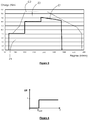
- Zone Z1 corresponds to a restricted zone, in which the operation of the vehicle is constrained by anti-pollution regulations, in particular of NO x discharge.
- Zone Z2 is an unregulated area.
- Each point contained in one of the zones Z1 and Z2 corresponds to a point of operation of the engine of the vehicle, defined by an engine speed and an engine load.
- a series of standard measurements of NO x variations evacuated at the outlet of the exhaust line 3 are carried out, in response to the injection of a determined quantity of reducing agent into the line. exhaust system of the motor vehicle.
- ⁇ ( NO x ) ETA i the standard value measured during the measurement of index i and Q i a test quantity of reducing agent injected to perform the measurement of index i.
- the different measurements of respective indices i are carried out for a set of reference operating points, denoted PF ETA. i , of the motor vehicle.
- test quantity Q i is here the same for all the measurements made, in other words whatever the point of operation. Alternatively, the test quantity Q i could vary depending on the operating point.
- FP ETA reference operating points i are here chosen in zone Z2, not subject to antipollution regulations. In this way, for each operating point of reference PF ETA i , a test quantity of injected reducing agent Q i and a corresponding measured standard value of variation ⁇ ( NO x ) ETA i , of NO x emitted or evacuated at the exit of the exhaust line. The variation thus measured is in fact a reduction of NO x evacuated.
- the set of triplets form a map standard, or reference stored in memory in the engine computer 7 (or alternatively in an external memory to which the computer 7 has access).
- the memorization of this mapping can be done in the factory during the design of the vehicle. It can also be stored in the computer 7, or in a memory connected to the computer 7, after commissioning of the vehicle, for example during an updating of the map.
- a first step S1 the vehicle engine is started.
- the engine speed sensor and means for determining the engine load determine, at a time t j, with j equal to 1 initially, the number of revolutions per minute of the engine, representing engine speed, and the MSY or engine torque, representing the engine load.
- the pair of speed / load values determined at the instant t j is transmitted to the computer 7.
- the second step S 2 is followed by a third test step S 3.
- the computer 7 detects whether the pair of speed / load values determined at time t j corresponds to an operating point of reference PF ETA i prerecorded.
- test S3 If the test S3 is negative, the process returns to the second step S2, the index j being incremented by 1, and new values of engine speed and engine load are determined at time t j + 1 .
- a fourth step S4 on command of the computer 7, the injection of reducing agent of the tank 1 is momentarily stopped for a predetermined duration.
- the momentary injection of reducing agent injection then makes it possible to measure the quantity E 0 of NO x evacuated by the exhaust line 3 without reduction by this agent.
- a fifth step S5 the quantity E 0 of NO x evacuated at the end of the exhaust line 3, following the reduction agent injection stoppage, is measured using the probe 6 .
- the measured value E 0 is transmitted to the computer 7.
- the process then proceeds to a sixth step S6 in which, on command of the computer 7, the injector 2 injects into the exhaust line 3, upstream of the SCR device 5, a predetermined quantity Qi of reducing agent.
- the quantity of agent Qi injected is the quantity pre-stored in memory, corresponding to the operating point of reference PF ETA i detected in the third step S3.
- the probe 6 measures the quantity E 1 of NO x evacuated in response to the injection of the reducing agent during step S6.
- the measured value E 1 is transmitted to the computer 7.
- the computer 7 subtracts the expected value of variation of NO x (that is to say the standard value corrected by the aging factor and by the coefficient of efficiency), either ⁇ NOT O x AND AT i * K * EFF T , to the measured NO x variation value, ie ⁇ ( NO x ) MES , and determines the absolute value of the result of this subtraction.
- DELTA_ ⁇ NO x denotes the result obtained (in absolute value) corresponding to a difference between the measured and expected NO x variations.
- step S10 comparing the result obtained in step S9, DELTA_ ⁇ NO x , to a predefined difference threshold, denoted S_ ⁇ NO x .
- the computer 7 detects that the quality of the reducing agent is good and the process returns to Step S2.
- the warning light 8 is not lit. The process then returns to the second step S2.
- the computer 7 detects that the quality of the reducing agent is poor and, during an eleventh step S11, controls the turn on the warning light 8.
- the method compares the ⁇ ( NO x ) MES measured NO x variation value and the standard NO x variation value, corrected by the aging factor and the efficiency coefficient. This corrected standard variation value corresponds to an expected variation value.
- a predetermined amount of reducing agent is injected upon detection of an operating point located in zone Z2.
- a specific amount called “Additional” reducing agent at an operating point of the engine for which a quantity of predefined reducing agent, called “base”, is already injected.
- the variation of NO x at the output of the SCR device 5 due to this surplus of reducing agent would be compared with a standard variation of prerecorded NO x (previously measured after injection of the amount of reducing agent base).
Landscapes
- Engineering & Computer Science (AREA)
- Chemical & Material Sciences (AREA)
- Combustion & Propulsion (AREA)
- Chemical Kinetics & Catalysis (AREA)
- Mechanical Engineering (AREA)
- General Engineering & Computer Science (AREA)
- Health & Medical Sciences (AREA)
- Toxicology (AREA)
- Biomedical Technology (AREA)
- Environmental & Geological Engineering (AREA)
- Analytical Chemistry (AREA)
- General Chemical & Material Sciences (AREA)
- Oil, Petroleum & Natural Gas (AREA)
- Exhaust Gas After Treatment (AREA)
Claims (7)
- Verfahren zum Steuern der Qualität eines selektiven katalytischen Stickoxid-Reduktionsmittels, das in eine Abgasleitung (3) eines Kraftfahrzeugs eingeleitet wird, das die folgenden Schritte umfasst:- Einleiten (S6) einer bestimmten Menge des Reduktionsmittels in die Abgasleitung (3);- Messen (S7-S8) einer Veränderung in Reaktion auf das Einleiten der ausgelassenen Stickoxidmenge;- Vergleichen der gemessenen Veränderung mit einer erwarteten Veränderung (S9-S10);dadurch gekennzeichnet, dass während des Betriebs des Kraftfahrzeugs ein Schritt (S3) des Detektierens eines im Voraus definierten Betriebspunkts des Kraftfahrzeugs unter einer Gesamtheit von im Voraus registrierten Betriebspunkten, die in einem Speicher jeweils einem Stickoxid-Standardveränderungswert zugeordnet sind, in Reaktion auf das Einleiten einer bestimmten Menge eines Reduktionsmittels vorgesehen ist, wobei ein erwarteter Veränderungswert anhand des Standardveränderungswerts, der dem detektierten Betriebspunkt zugeordnet ist, bestimmt wird, dass der Schritt (S6) des Einleitens einer bestimmten Menge des Reduktionsmittels bei einer Detektion (S2-S3) des im Voraus definierten Betriebspunkts des Kraftfahrzeugs ausgelöst wird und dass das Verfahren einen Schritt des Subtrahierens des erwarteten Veränderungswertes von dem gemessenen Veränderungswert, einen Schritt des Vergleichens des Ergebnisses der Subtraktion dem Absolutwert nach mit einem im Voraus definierten Differenzschwellenwert und des Detektierens, dass die Menge des Reduktionsmittels in Ordnung ist, falls das Ergebnis der Subtraktion kleiner als der Schwellenwert ist, oder nicht in Ordnung ist, falls das Ergebnis der Subtraktion größer als der Schwellenwert ist, umfasst.
- Verfahren nach Anspruch 1, dadurch gekennzeichnet, dass der Betriebspunkt zu einem Betriebsbereich des Kraftfahrzeugs gehört, der keinen Reglementierungsbeschränkungen unterliegt.
- Verfahren nach einem der Ansprüche 1 und 2, dadurch gekennzeichnet, dass dem Schritt (S6) des Einleitens einer bestimmten Menge des Reduktionsmittels ein Schritt (S4) des Beendens des Einleitens des Reduktionsmittels und ein Schritt (S5) des Messens der Menge an Stickoxiden, die in Reaktion auf das Unterbrechen der Einleitung des Reduktionsmittels abgeführt wird, vorhergehen.
- Verfahren nach einem der Ansprüche 1 bis 3, dadurch gekennzeichnet, dass die erwartete Veränderung durch Korrigieren der im Voraus registrierten Standardveränderung mit einem Alterungsfaktor bestimmt (S9) wird.
- Verfahren nach einem der Ansprüche 1 bis 4, dadurch gekennzeichnet, dass die erwartete Veränderung durch Korrigieren der im Voraus registrierten Standardveränderung mit einem von der Betriebstemperatur abhängigen Wirkungsgradkoeffizienten bestimmt (S9) wird.
- System zum Steuern der Qualität eines katalytischen Stickoxid-Reduktionsmittels, das in eine Abgasleitung eines Kraftfahrzeugs eingeleitet wird, das Folgendes umfasst:- eine Vorrichtung (2) zum Einleiten des Reduktionsmittels in die Abgasleitung;- eine Vorrichtung (6) zum Messen einer abgeführten Stickoxidmenge nach einer katalytischen Reduktion;- ein Steuermodul (7), das dafür ausgelegt ist, ein Einleiten einer bestimmten Menge des Reduktionsmittels zu steuern, eine Veränderung der Stickoxidmenge, die nach der katalytischen Reduktion in Reaktion auf die Einleitung abgeführt wird, anhand von gemessenen Werten zu berechnen und gemessene Veränderung und eine im Voraus registrierte erwartete Veränderung zu vergleichen;dadurch gekennzeichnet, dass das Steuermodul dafür ausgelegt ist, während des Betriebs des Kraftfahrzeugs einen im Voraus definierten Betriebspunkt des Kraftfahrzeugs aus einer Gesamtheit vom im Voraus registrierten Betriebspunkten, die in einem Speicher jeweils einem Stickoxid-Standardveränderungswert zugeordnet sind, in Reaktion auf eine Einleitung einer bestimmten Menge des Reduktionsmittels zu detektieren, um einen erwarteten Veränderungswert anhand des Standardveränderungswertes, der dem detektierten Betriebspunkt zugeordnet ist, zu bestimmen, um eine Einleitung einer Menge des Reduktionsmittels in die Abgasleitung bei Detektion (S2-S3) des im Voraus definierten Betriebspunkts des Kraftfahrzeugs auszulösen und um den erwarteten Veränderungswert von dem gemessenen Veränderungswert zu subtrahieren, um das Ergebnis der Subtraktion dem Absolutwert nach mit einem im Voraus definierten Schwellenwert zu vergleichen und um zu detektieren, dass die Menge des Reduktionsmittels in Ordnung ist, falls das Ergebnis der Subtraktion kleiner als der Schwellenwert ist, oder nicht in Ordnung ist, falls das Ergebnis der Subtraktion größer als der Schwellenwert ist.
- Software-Modul für ein System zum Steuern der Qualität eines katalytischen Stickoxid-Reduktionsmittels, das in eine Abgasleitung eines Kraftfahrzeugs eingeleitet wird, das Software-Befehle enthält zum:- Detektieren eines im Voraus definierten Betriebspunkts des Kraftfahrzeugs aus einer Gesamtheit von im Voraus registrierten Betriebspunkten, die jeweils im Speicher einem Stickoxid-Standardveränderungswert zugeordnet sind, in Reaktion auf eine Einleitung einer bestimmten Menge des Reduktionsmittels während des Betriebs des Kraftfahrzeugs,- Bestimmen eines erwarteten Veränderungswertes anhand des dem detektierten Betriebspunkt zugeordneten Standardveränderungswertes,- Steuern eines Einleitens einer bestimmten Menge des Reduktionsmittels in die Abgasleitung bei Detektion des im Voraus definierten Betriebspunkts des Kraftfahrzeugs,- Berechnen eines gemessenen Veränderungswerts der Stickoxidmenge, die nach einer katalytischen Reduktion abgeführt wird, in Reaktion auf das Einleiten anhand gemessener Werte,- Subtrahieren des erwarteten Veränderungswerts von dem gemessenen Veränderungswert,- Vergleichen des Ergebnisses der Subtraktion dem Absolutwert nach mit einem im Voraus definierten Differenzschwellenwert und- Detektieren, dass die Menge des Reduktionsmittels in Ordnung ist, falls das Ergebnis der Subtraktion kleiner als der Schwellenwert ist, oder nicht in Ordnung ist, falls das Ergebnis der Subtraktion größer als der Schwellenwert ist,wenn das Software-Modul von einem Prozessor ausgeführt wird.
Applications Claiming Priority (1)
| Application Number | Priority Date | Filing Date | Title |
|---|---|---|---|
| FR1354836A FR3006371B1 (fr) | 2013-05-28 | 2013-05-28 | Procede et systeme de controle de la qualite d'un agent de reduction catalytique selective d'oxydes d'azote, injecte dans une ligne d'echappement d'un vehicule automobile |
Publications (2)
| Publication Number | Publication Date |
|---|---|
| EP2808510A1 EP2808510A1 (de) | 2014-12-03 |
| EP2808510B1 true EP2808510B1 (de) | 2018-07-04 |
Family
ID=49054744
Family Applications (1)
| Application Number | Title | Priority Date | Filing Date |
|---|---|---|---|
| EP14305762.8A Active EP2808510B1 (de) | 2013-05-28 | 2014-05-23 | Qualitätskontrollverfahren und -system eines selektiven katalytischen reduktionsmittels von stickoxiden, das in die auspuffanlage eines kraftfahrzeugs eingespritzt wird |
Country Status (2)
| Country | Link |
|---|---|
| EP (1) | EP2808510B1 (de) |
| FR (1) | FR3006371B1 (de) |
Families Citing this family (2)
| Publication number | Priority date | Publication date | Assignee | Title |
|---|---|---|---|---|
| CN104857853A (zh) * | 2015-05-27 | 2015-08-26 | 山东应天节能环保科技有限公司 | 一种根据烟气中硫硝含量输送粉体催化剂的输送装置 |
| CN109339916B (zh) * | 2018-09-30 | 2020-09-01 | 广西玉柴机器股份有限公司 | 一种SCR下游NOx闭环过程中的控制方法及系统 |
Family Cites Families (4)
| Publication number | Priority date | Publication date | Assignee | Title |
|---|---|---|---|---|
| CN100587235C (zh) * | 2005-09-29 | 2010-02-03 | 沃尔沃拉斯特瓦格纳公司 | 用于排气后处理系统的诊断方法 |
| FR2907160B1 (fr) * | 2006-10-13 | 2008-12-26 | Peugeot Citroen Automobiles Sa | Procede de controle en boucle fermee de quantite d'uree pour systeme de traitement d'oxydes d'azote |
| JP4661814B2 (ja) * | 2007-03-29 | 2011-03-30 | トヨタ自動車株式会社 | 内燃機関の排気浄化装置 |
| US7832200B2 (en) * | 2008-04-23 | 2010-11-16 | Caterpillar Inc | Exhaust system implementing feedforward and feedback control |
-
2013
- 2013-05-28 FR FR1354836A patent/FR3006371B1/fr not_active Expired - Fee Related
-
2014
- 2014-05-23 EP EP14305762.8A patent/EP2808510B1/de active Active
Non-Patent Citations (1)
| Title |
|---|
| None * |
Also Published As
| Publication number | Publication date |
|---|---|
| EP2808510A1 (de) | 2014-12-03 |
| FR3006371B1 (fr) | 2017-04-28 |
| FR3006371A1 (fr) | 2014-12-05 |
Similar Documents
| Publication | Publication Date | Title |
|---|---|---|
| EP2274506B1 (de) | Verfahren zur korrektur von stickoxidemissionsmodellen | |
| EP3014082B1 (de) | System und verfahren zur diagnose des selektiven katalytischen reduktionssystems eines kraftfahrzeugs | |
| FR3029973A1 (fr) | Procede de surveillance d'un dispositif de catalyse d'oxydation | |
| FR2928691A1 (fr) | Procede et dispositif pour surveiller un systeme d'alimentation en air d'un moteur a combustion interne | |
| CN106321206A (zh) | 一种实时在线计算的NOx排放监控方法 | |
| US9068495B2 (en) | Oxidation catalyst/hydrocarbon injector testing system | |
| EP2932059B1 (de) | Verfahren zur diagnose einer stickoxidfalle | |
| EP1864007B1 (de) | Verfahren und vorrichtung zur überwachung eines teilchenfilters in der abgasleitung eines verbrennungsmotors | |
| EP2808510B1 (de) | Qualitätskontrollverfahren und -system eines selektiven katalytischen reduktionsmittels von stickoxiden, das in die auspuffanlage eines kraftfahrzeugs eingespritzt wird | |
| EP3387230B1 (de) | Verfahren zur diagnose eines katalysators zur selektiven reduktion von stickoxiden eines motors und zugehörige vorrichtung | |
| FR3062418B1 (fr) | Procede de controle des emissions d'oxydes d'azote a l'echappement d'un moteur a combustion interne | |
| EP3234326B1 (de) | Diagnoseverfahren für ein abgasrückführsystem eines kraftfahrzeugmotors | |
| FR2915765A1 (fr) | Procede et systeme de diagnostic sur la composition d'un reservoir,pour controler une injection sur catalyseur de reduction des oxydes d'azotes | |
| FR3069574B1 (fr) | Procede d'adaptation d'une quantite d'agent reducteur pour une depollution en oxydes d'azote des gaz dans une ligne d'echappement de moteur | |
| EP2802760B1 (de) | Optimierte verwaltung eines scr-katalysators mittels periodischer regeneration eines partikelfilters | |
| EP3359787B1 (de) | Verfahren zur diagnose eines katalysators zur selektiven reduktion von stickoxiden | |
| FR2914355A1 (fr) | Procede et dispositif de diagnosti d'une installation de nettoyage des gaz d'echappement. | |
| EP2466087B1 (de) | Diagnoseverfahren eines SCR-Systems für ein Kraftfahrzeug, sowie entsprechendes Kraftfahrzeug | |
| EP1739291B1 (de) | System zur Regeneration von in der Abgasleitung eines Kraftfahrzeugmotors integrierten Reinigungsvorrichtungen | |
| FR2948979A1 (fr) | Methode de diagnostic et de controle d'un capteur d'oxydes d'azote | |
| EP2193261B1 (de) | Verfahren und vorrichtung zur handhabung eines abgasbehandlungsmoduls | |
| EP1327760B1 (de) | Verfahren zur Bestimmung der zugeführten Gasmenge in einer Brennkraftmaschine eines Kraftfahrzeugs | |
| WO2013139526A1 (fr) | Procédé de détermination de la quantité d'ammoniac stockée dans un catalyseur, et système correspondant | |
| EP3511540A1 (de) | Kontrollverfahren eines systems zur selektiven katalytischen reduktion | |
| FR2951501B1 (fr) | Procede de gestion d'un dispositif de post-traitement des gaz d'echappement et installation de commande et/ou de regulation pour sa mise en oeuvre |
Legal Events
| Date | Code | Title | Description |
|---|---|---|---|
| PUAI | Public reference made under article 153(3) epc to a published international application that has entered the european phase |
Free format text: ORIGINAL CODE: 0009012 |
|
| 17P | Request for examination filed |
Effective date: 20140523 |
|
| AK | Designated contracting states |
Kind code of ref document: A1 Designated state(s): AL AT BE BG CH CY CZ DE DK EE ES FI FR GB GR HR HU IE IS IT LI LT LU LV MC MK MT NL NO PL PT RO RS SE SI SK SM TR |
|
| AX | Request for extension of the european patent |
Extension state: BA ME |
|
| R17P | Request for examination filed (corrected) |
Effective date: 20150324 |
|
| RBV | Designated contracting states (corrected) |
Designated state(s): AL AT BE BG CH CY CZ DE DK EE ES FI FR GB GR HR HU IE IS IT LI LT LU LV MC MK MT NL NO PL PT RO RS SE SI SK SM TR |
|
| 17Q | First examination report despatched |
Effective date: 20151027 |
|
| RIC1 | Information provided on ipc code assigned before grant |
Ipc: F01N 3/20 20060101AFI20171106BHEP Ipc: F01N 3/021 20060101ALN20171106BHEP Ipc: F01N 3/10 20060101ALN20171106BHEP Ipc: B01D 53/94 20060101ALI20171106BHEP Ipc: F01N 5/04 20060101ALN20171106BHEP Ipc: F01N 13/02 20100101ALN20171106BHEP |
|
| GRAP | Despatch of communication of intention to grant a patent |
Free format text: ORIGINAL CODE: EPIDOSNIGR1 |
|
| STAA | Information on the status of an ep patent application or granted ep patent |
Free format text: STATUS: GRANT OF PATENT IS INTENDED |
|
| INTG | Intention to grant announced |
Effective date: 20180122 |
|
| GRAS | Grant fee paid |
Free format text: ORIGINAL CODE: EPIDOSNIGR3 |
|
| GRAA | (expected) grant |
Free format text: ORIGINAL CODE: 0009210 |
|
| STAA | Information on the status of an ep patent application or granted ep patent |
Free format text: STATUS: THE PATENT HAS BEEN GRANTED |
|
| AK | Designated contracting states |
Kind code of ref document: B1 Designated state(s): AL AT BE BG CH CY CZ DE DK EE ES FI FR GB GR HR HU IE IS IT LI LT LU LV MC MK MT NL NO PL PT RO RS SE SI SK SM TR |
|
| REG | Reference to a national code |
Ref country code: GB Ref legal event code: FG4D Free format text: NOT ENGLISH |
|
| REG | Reference to a national code |
Ref country code: CH Ref legal event code: EP |
|
| REG | Reference to a national code |
Ref country code: AT Ref legal event code: REF Ref document number: 1014746 Country of ref document: AT Kind code of ref document: T Effective date: 20180715 |
|
| REG | Reference to a national code |
Ref country code: IE Ref legal event code: FG4D Free format text: LANGUAGE OF EP DOCUMENT: FRENCH |
|
| REG | Reference to a national code |
Ref country code: DE Ref legal event code: R096 Ref document number: 602014027804 Country of ref document: DE |
|
| REG | Reference to a national code |
Ref country code: NL Ref legal event code: MP Effective date: 20180704 |
|
| REG | Reference to a national code |
Ref country code: LT Ref legal event code: MG4D |
|
| REG | Reference to a national code |
Ref country code: AT Ref legal event code: MK05 Ref document number: 1014746 Country of ref document: AT Kind code of ref document: T Effective date: 20180704 |
|
| PG25 | Lapsed in a contracting state [announced via postgrant information from national office to epo] |
Ref country code: NL Free format text: LAPSE BECAUSE OF FAILURE TO SUBMIT A TRANSLATION OF THE DESCRIPTION OR TO PAY THE FEE WITHIN THE PRESCRIBED TIME-LIMIT Effective date: 20180704 |
|
| PG25 | Lapsed in a contracting state [announced via postgrant information from national office to epo] |
Ref country code: GR Free format text: LAPSE BECAUSE OF FAILURE TO SUBMIT A TRANSLATION OF THE DESCRIPTION OR TO PAY THE FEE WITHIN THE PRESCRIBED TIME-LIMIT Effective date: 20181005 Ref country code: BG Free format text: LAPSE BECAUSE OF FAILURE TO SUBMIT A TRANSLATION OF THE DESCRIPTION OR TO PAY THE FEE WITHIN THE PRESCRIBED TIME-LIMIT Effective date: 20181004 Ref country code: SE Free format text: LAPSE BECAUSE OF FAILURE TO SUBMIT A TRANSLATION OF THE DESCRIPTION OR TO PAY THE FEE WITHIN THE PRESCRIBED TIME-LIMIT Effective date: 20180704 Ref country code: LT Free format text: LAPSE BECAUSE OF FAILURE TO SUBMIT A TRANSLATION OF THE DESCRIPTION OR TO PAY THE FEE WITHIN THE PRESCRIBED TIME-LIMIT Effective date: 20180704 Ref country code: PL Free format text: LAPSE BECAUSE OF FAILURE TO SUBMIT A TRANSLATION OF THE DESCRIPTION OR TO PAY THE FEE WITHIN THE PRESCRIBED TIME-LIMIT Effective date: 20180704 Ref country code: FI Free format text: LAPSE BECAUSE OF FAILURE TO SUBMIT A TRANSLATION OF THE DESCRIPTION OR TO PAY THE FEE WITHIN THE PRESCRIBED TIME-LIMIT Effective date: 20180704 Ref country code: CZ Free format text: LAPSE BECAUSE OF FAILURE TO SUBMIT A TRANSLATION OF THE DESCRIPTION OR TO PAY THE FEE WITHIN THE PRESCRIBED TIME-LIMIT Effective date: 20180704 Ref country code: RS Free format text: LAPSE BECAUSE OF FAILURE TO SUBMIT A TRANSLATION OF THE DESCRIPTION OR TO PAY THE FEE WITHIN THE PRESCRIBED TIME-LIMIT Effective date: 20180704 Ref country code: AT Free format text: LAPSE BECAUSE OF FAILURE TO SUBMIT A TRANSLATION OF THE DESCRIPTION OR TO PAY THE FEE WITHIN THE PRESCRIBED TIME-LIMIT Effective date: 20180704 Ref country code: NO Free format text: LAPSE BECAUSE OF FAILURE TO SUBMIT A TRANSLATION OF THE DESCRIPTION OR TO PAY THE FEE WITHIN THE PRESCRIBED TIME-LIMIT Effective date: 20181004 Ref country code: IS Free format text: LAPSE BECAUSE OF FAILURE TO SUBMIT A TRANSLATION OF THE DESCRIPTION OR TO PAY THE FEE WITHIN THE PRESCRIBED TIME-LIMIT Effective date: 20181104 |
|
| PG25 | Lapsed in a contracting state [announced via postgrant information from national office to epo] |
Ref country code: AL Free format text: LAPSE BECAUSE OF FAILURE TO SUBMIT A TRANSLATION OF THE DESCRIPTION OR TO PAY THE FEE WITHIN THE PRESCRIBED TIME-LIMIT Effective date: 20180704 Ref country code: ES Free format text: LAPSE BECAUSE OF FAILURE TO SUBMIT A TRANSLATION OF THE DESCRIPTION OR TO PAY THE FEE WITHIN THE PRESCRIBED TIME-LIMIT Effective date: 20180704 Ref country code: HR Free format text: LAPSE BECAUSE OF FAILURE TO SUBMIT A TRANSLATION OF THE DESCRIPTION OR TO PAY THE FEE WITHIN THE PRESCRIBED TIME-LIMIT Effective date: 20180704 Ref country code: LV Free format text: LAPSE BECAUSE OF FAILURE TO SUBMIT A TRANSLATION OF THE DESCRIPTION OR TO PAY THE FEE WITHIN THE PRESCRIBED TIME-LIMIT Effective date: 20180704 |
|
| REG | Reference to a national code |
Ref country code: DE Ref legal event code: R097 Ref document number: 602014027804 Country of ref document: DE |
|
| PG25 | Lapsed in a contracting state [announced via postgrant information from national office to epo] |
Ref country code: RO Free format text: LAPSE BECAUSE OF FAILURE TO SUBMIT A TRANSLATION OF THE DESCRIPTION OR TO PAY THE FEE WITHIN THE PRESCRIBED TIME-LIMIT Effective date: 20180704 Ref country code: IT Free format text: LAPSE BECAUSE OF FAILURE TO SUBMIT A TRANSLATION OF THE DESCRIPTION OR TO PAY THE FEE WITHIN THE PRESCRIBED TIME-LIMIT Effective date: 20180704 Ref country code: EE Free format text: LAPSE BECAUSE OF FAILURE TO SUBMIT A TRANSLATION OF THE DESCRIPTION OR TO PAY THE FEE WITHIN THE PRESCRIBED TIME-LIMIT Effective date: 20180704 |
|
| PLBE | No opposition filed within time limit |
Free format text: ORIGINAL CODE: 0009261 |
|
| STAA | Information on the status of an ep patent application or granted ep patent |
Free format text: STATUS: NO OPPOSITION FILED WITHIN TIME LIMIT |
|
| PG25 | Lapsed in a contracting state [announced via postgrant information from national office to epo] |
Ref country code: SK Free format text: LAPSE BECAUSE OF FAILURE TO SUBMIT A TRANSLATION OF THE DESCRIPTION OR TO PAY THE FEE WITHIN THE PRESCRIBED TIME-LIMIT Effective date: 20180704 Ref country code: DK Free format text: LAPSE BECAUSE OF FAILURE TO SUBMIT A TRANSLATION OF THE DESCRIPTION OR TO PAY THE FEE WITHIN THE PRESCRIBED TIME-LIMIT Effective date: 20180704 Ref country code: SM Free format text: LAPSE BECAUSE OF FAILURE TO SUBMIT A TRANSLATION OF THE DESCRIPTION OR TO PAY THE FEE WITHIN THE PRESCRIBED TIME-LIMIT Effective date: 20180704 |
|
| 26N | No opposition filed |
Effective date: 20190405 |
|
| PG25 | Lapsed in a contracting state [announced via postgrant information from national office to epo] |
Ref country code: SI Free format text: LAPSE BECAUSE OF FAILURE TO SUBMIT A TRANSLATION OF THE DESCRIPTION OR TO PAY THE FEE WITHIN THE PRESCRIBED TIME-LIMIT Effective date: 20180704 |
|
| REG | Reference to a national code |
Ref country code: CH Ref legal event code: PL |
|
| GBPC | Gb: european patent ceased through non-payment of renewal fee |
Effective date: 20190523 |
|
| PG25 | Lapsed in a contracting state [announced via postgrant information from national office to epo] |
Ref country code: CH Free format text: LAPSE BECAUSE OF NON-PAYMENT OF DUE FEES Effective date: 20190531 Ref country code: LI Free format text: LAPSE BECAUSE OF NON-PAYMENT OF DUE FEES Effective date: 20190531 Ref country code: MC Free format text: LAPSE BECAUSE OF FAILURE TO SUBMIT A TRANSLATION OF THE DESCRIPTION OR TO PAY THE FEE WITHIN THE PRESCRIBED TIME-LIMIT Effective date: 20180704 |
|
| REG | Reference to a national code |
Ref country code: BE Ref legal event code: MM Effective date: 20190531 |
|
| PG25 | Lapsed in a contracting state [announced via postgrant information from national office to epo] |
Ref country code: LU Free format text: LAPSE BECAUSE OF NON-PAYMENT OF DUE FEES Effective date: 20190523 |
|
| PG25 | Lapsed in a contracting state [announced via postgrant information from national office to epo] |
Ref country code: TR Free format text: LAPSE BECAUSE OF FAILURE TO SUBMIT A TRANSLATION OF THE DESCRIPTION OR TO PAY THE FEE WITHIN THE PRESCRIBED TIME-LIMIT Effective date: 20180704 |
|
| PG25 | Lapsed in a contracting state [announced via postgrant information from national office to epo] |
Ref country code: IE Free format text: LAPSE BECAUSE OF NON-PAYMENT OF DUE FEES Effective date: 20190523 Ref country code: GB Free format text: LAPSE BECAUSE OF NON-PAYMENT OF DUE FEES Effective date: 20190523 |
|
| PG25 | Lapsed in a contracting state [announced via postgrant information from national office to epo] |
Ref country code: BE Free format text: LAPSE BECAUSE OF NON-PAYMENT OF DUE FEES Effective date: 20190531 |
|
| PG25 | Lapsed in a contracting state [announced via postgrant information from national office to epo] |
Ref country code: PT Free format text: LAPSE BECAUSE OF FAILURE TO SUBMIT A TRANSLATION OF THE DESCRIPTION OR TO PAY THE FEE WITHIN THE PRESCRIBED TIME-LIMIT Effective date: 20181105 |
|
| PG25 | Lapsed in a contracting state [announced via postgrant information from national office to epo] |
Ref country code: CY Free format text: LAPSE BECAUSE OF FAILURE TO SUBMIT A TRANSLATION OF THE DESCRIPTION OR TO PAY THE FEE WITHIN THE PRESCRIBED TIME-LIMIT Effective date: 20180704 |
|
| PG25 | Lapsed in a contracting state [announced via postgrant information from national office to epo] |
Ref country code: MT Free format text: LAPSE BECAUSE OF FAILURE TO SUBMIT A TRANSLATION OF THE DESCRIPTION OR TO PAY THE FEE WITHIN THE PRESCRIBED TIME-LIMIT Effective date: 20180704 Ref country code: HU Free format text: LAPSE BECAUSE OF FAILURE TO SUBMIT A TRANSLATION OF THE DESCRIPTION OR TO PAY THE FEE WITHIN THE PRESCRIBED TIME-LIMIT; INVALID AB INITIO Effective date: 20140523 |
|
| PG25 | Lapsed in a contracting state [announced via postgrant information from national office to epo] |
Ref country code: MK Free format text: LAPSE BECAUSE OF FAILURE TO SUBMIT A TRANSLATION OF THE DESCRIPTION OR TO PAY THE FEE WITHIN THE PRESCRIBED TIME-LIMIT Effective date: 20180704 |
|
| P01 | Opt-out of the competence of the unified patent court (upc) registered |
Effective date: 20230608 |
|
| REG | Reference to a national code |
Ref country code: DE Ref legal event code: R081 Ref document number: 602014027804 Country of ref document: DE Owner name: NEW H POWERTRAIN HOLDING, S.L.U., ES Free format text: FORMER OWNER: RENAULT S.A.S., BOULOGNE-BILLANCOURT, FR |
|
| PGFP | Annual fee paid to national office [announced via postgrant information from national office to epo] |
Ref country code: DE Payment date: 20250521 Year of fee payment: 12 |
|
| PGFP | Annual fee paid to national office [announced via postgrant information from national office to epo] |
Ref country code: FR Payment date: 20250528 Year of fee payment: 12 |