EP2808217A1 - Vehicle safety arrangement and method - Google Patents
Vehicle safety arrangement and method Download PDFInfo
- Publication number
- EP2808217A1 EP2808217A1 EP13169358.2A EP13169358A EP2808217A1 EP 2808217 A1 EP2808217 A1 EP 2808217A1 EP 13169358 A EP13169358 A EP 13169358A EP 2808217 A1 EP2808217 A1 EP 2808217A1
- Authority
- EP
- European Patent Office
- Prior art keywords
- host vehicle
- vehicle
- behind
- intention
- determining
- Prior art date
- Legal status (The legal status is an assumption and is not a legal conclusion. Google has not performed a legal analysis and makes no representation as to the accuracy of the status listed.)
- Granted
Links
- 238000000034 method Methods 0.000 title claims abstract description 12
- 238000001514 detection method Methods 0.000 claims abstract description 33
- 230000000116 mitigating effect Effects 0.000 claims abstract description 11
- 238000002604 ultrasonography Methods 0.000 claims description 6
- 230000005540 biological transmission Effects 0.000 claims description 3
- 230000006378 damage Effects 0.000 description 2
- 230000003321 amplification Effects 0.000 description 1
- 230000000295 complement effect Effects 0.000 description 1
- 230000004927 fusion Effects 0.000 description 1
- 229910044991 metal oxide Inorganic materials 0.000 description 1
- 150000004706 metal oxides Chemical class 0.000 description 1
- 238000003199 nucleic acid amplification method Methods 0.000 description 1
- 230000005855 radiation Effects 0.000 description 1
- 239000004065 semiconductor Substances 0.000 description 1
- 238000006467 substitution reaction Methods 0.000 description 1
Images


Classifications
-
- G—PHYSICS
- G08—SIGNALLING
- G08G—TRAFFIC CONTROL SYSTEMS
- G08G1/00—Traffic control systems for road vehicles
- G08G1/16—Anti-collision systems
- G08G1/167—Driving aids for lane monitoring, lane changing, e.g. blind spot detection
-
- B—PERFORMING OPERATIONS; TRANSPORTING
- B60—VEHICLES IN GENERAL
- B60W—CONJOINT CONTROL OF VEHICLE SUB-UNITS OF DIFFERENT TYPE OR DIFFERENT FUNCTION; CONTROL SYSTEMS SPECIALLY ADAPTED FOR HYBRID VEHICLES; ROAD VEHICLE DRIVE CONTROL SYSTEMS FOR PURPOSES NOT RELATED TO THE CONTROL OF A PARTICULAR SUB-UNIT
- B60W10/00—Conjoint control of vehicle sub-units of different type or different function
- B60W10/20—Conjoint control of vehicle sub-units of different type or different function including control of steering systems
-
- B—PERFORMING OPERATIONS; TRANSPORTING
- B60—VEHICLES IN GENERAL
- B60W—CONJOINT CONTROL OF VEHICLE SUB-UNITS OF DIFFERENT TYPE OR DIFFERENT FUNCTION; CONTROL SYSTEMS SPECIALLY ADAPTED FOR HYBRID VEHICLES; ROAD VEHICLE DRIVE CONTROL SYSTEMS FOR PURPOSES NOT RELATED TO THE CONTROL OF A PARTICULAR SUB-UNIT
- B60W30/00—Purposes of road vehicle drive control systems not related to the control of a particular sub-unit, e.g. of systems using conjoint control of vehicle sub-units, or advanced driver assistance systems for ensuring comfort, stability and safety or drive control systems for propelling or retarding the vehicle
- B60W30/08—Active safety systems predicting or avoiding probable or impending collision or attempting to minimise its consequences
- B60W30/085—Taking automatic action to adjust vehicle attitude in preparation for collision, e.g. braking for nose dropping
-
- B—PERFORMING OPERATIONS; TRANSPORTING
- B60—VEHICLES IN GENERAL
- B60W—CONJOINT CONTROL OF VEHICLE SUB-UNITS OF DIFFERENT TYPE OR DIFFERENT FUNCTION; CONTROL SYSTEMS SPECIALLY ADAPTED FOR HYBRID VEHICLES; ROAD VEHICLE DRIVE CONTROL SYSTEMS FOR PURPOSES NOT RELATED TO THE CONTROL OF A PARTICULAR SUB-UNIT
- B60W30/00—Purposes of road vehicle drive control systems not related to the control of a particular sub-unit, e.g. of systems using conjoint control of vehicle sub-units, or advanced driver assistance systems for ensuring comfort, stability and safety or drive control systems for propelling or retarding the vehicle
- B60W30/08—Active safety systems predicting or avoiding probable or impending collision or attempting to minimise its consequences
- B60W30/095—Predicting travel path or likelihood of collision
- B60W30/0956—Predicting travel path or likelihood of collision the prediction being responsive to traffic or environmental parameters
-
- B—PERFORMING OPERATIONS; TRANSPORTING
- B62—LAND VEHICLES FOR TRAVELLING OTHERWISE THAN ON RAILS
- B62D—MOTOR VEHICLES; TRAILERS
- B62D15/00—Steering not otherwise provided for
- B62D15/02—Steering position indicators ; Steering position determination; Steering aids
- B62D15/025—Active steering aids, e.g. helping the driver by actively influencing the steering system after environment evaluation
- B62D15/0265—Automatic obstacle avoidance by steering
-
- B—PERFORMING OPERATIONS; TRANSPORTING
- B60—VEHICLES IN GENERAL
- B60W—CONJOINT CONTROL OF VEHICLE SUB-UNITS OF DIFFERENT TYPE OR DIFFERENT FUNCTION; CONTROL SYSTEMS SPECIALLY ADAPTED FOR HYBRID VEHICLES; ROAD VEHICLE DRIVE CONTROL SYSTEMS FOR PURPOSES NOT RELATED TO THE CONTROL OF A PARTICULAR SUB-UNIT
- B60W50/00—Details of control systems for road vehicle drive control not related to the control of a particular sub-unit, e.g. process diagnostic or vehicle driver interfaces
- B60W2050/0001—Details of the control system
- B60W2050/0002—Automatic control, details of type of controller or control system architecture
-
- B—PERFORMING OPERATIONS; TRANSPORTING
- B60—VEHICLES IN GENERAL
- B60W—CONJOINT CONTROL OF VEHICLE SUB-UNITS OF DIFFERENT TYPE OR DIFFERENT FUNCTION; CONTROL SYSTEMS SPECIALLY ADAPTED FOR HYBRID VEHICLES; ROAD VEHICLE DRIVE CONTROL SYSTEMS FOR PURPOSES NOT RELATED TO THE CONTROL OF A PARTICULAR SUB-UNIT
- B60W2540/00—Input parameters relating to occupants
- B60W2540/18—Steering angle
-
- B—PERFORMING OPERATIONS; TRANSPORTING
- B60—VEHICLES IN GENERAL
- B60W—CONJOINT CONTROL OF VEHICLE SUB-UNITS OF DIFFERENT TYPE OR DIFFERENT FUNCTION; CONTROL SYSTEMS SPECIALLY ADAPTED FOR HYBRID VEHICLES; ROAD VEHICLE DRIVE CONTROL SYSTEMS FOR PURPOSES NOT RELATED TO THE CONTROL OF A PARTICULAR SUB-UNIT
- B60W2552/00—Input parameters relating to infrastructure
-
- B—PERFORMING OPERATIONS; TRANSPORTING
- B60—VEHICLES IN GENERAL
- B60W—CONJOINT CONTROL OF VEHICLE SUB-UNITS OF DIFFERENT TYPE OR DIFFERENT FUNCTION; CONTROL SYSTEMS SPECIALLY ADAPTED FOR HYBRID VEHICLES; ROAD VEHICLE DRIVE CONTROL SYSTEMS FOR PURPOSES NOT RELATED TO THE CONTROL OF A PARTICULAR SUB-UNIT
- B60W2556/00—Input parameters relating to data
- B60W2556/45—External transmission of data to or from the vehicle
- B60W2556/50—External transmission of data to or from the vehicle for navigation systems
Definitions
- Embodiments herein relate to a vehicle safety arrangement for preventing or mitigating accidents when turning across lanes with oncoming traffic in a vehicle hosting the arrangement, the host vehicle further comprising an Electrical Power Assisted Steering operable to steer one or more wheels of the host vehicle.
- Still further embodiments herein relate to a motor vehicle comprising a vehicle safety arrangement for preventing or mitigating accidents when turning across lanes with oncoming traffic in a vehicle hosting the arrangement, the host vehicle further comprising an Electrical Power Assisted Steering operable to steer one or more wheels of the host vehicle.
- Embodiments herein aim to provide an improved vehicle safety arrangement for preventing or mitigating accidents when turning across lanes with oncoming traffic in a vehicle hosting the arrangement, the host vehicle further comprising an Electrical Power Assisted Steering operable to steer one or more wheels of the host vehicle.
- the arrangement comprising: one or more forward-looking detection systems for detecting oncoming traffic in one or more lanes adjacent to the lane travelled by the host vehicle; one or more rearward-looking detection systems for detecting other vehicles approaching the host vehicle from behind; one or more turning intention detection systems for determining an intention to turn across an adjacent lane; means for determining standstill of the host vehicle: a control unit arranged to, during determined standstill of the host vehicle and a determined intention to turn across a lane containing oncoming traffic, determine a risk of the host vehicle being hit from behind; and, upon determining a high risk of the host vehicle being hit from behind, generate and send a control signal to a vehicle Electrical Power Assisted Steering control unit, which Electrical Power Assisted Steering control unit, in response to receiving such a control signal, is arranged to cause the Electrical Power Assisted Steering to align the steerable wheels of the host vehicle.
- the provision to align the steerable wheels of the host vehicle during determined standstill of the host vehicle and a determined intention to turn across a lane containing oncoming traffic upon determining a high risk of the host vehicle being hit from behind is ensured that any pushing of the host vehicle as a result of the host vehicle being hit by another vehicle from behind, will only cause the vehicle to move straight forward in the current lane, and thus not turn into a lane containing oncoming traffic and potentially suffer a secondary collision therewith.
- the one or more forward-looking detection systems comprises one or more of a radar sensor, a laser sensor, a lidar sensor, an ultrasound sensor, an infrared sensor, one or several image sensors, or any combination thereof.
- the one or more rearward-looking detection systems comprises one or more of a radar sensor, a laser sensor, a lidar sensor, an ultrasound sensor, an infrared sensor, one or several image sensors, or any combination thereof.
- the one or more turning intention detection systems are arranged to determine an intention to turn across an adjacent lane from one or more parameters, such as left or right hand steering wheel movement, turning of the steerable wheels of the host vehicle, steering angle, information on the extension of the road from at least one of a camera sensor, a map data system and a navigation system.
- the provision of determining an intention to turn across an adjacent lane from one or more of the above parameters facilitates cost efficient realization of the arrangement as determination can be made using sensors that are normally already present in today's vehicles.
- the means for determining standstill are arranged to determine standstill of the host vehicle from at least one of a vehicle speed sensor, two or more vehicle speed sensors, a transmission sensor and a navigation system.
- Determining standstill of the host vehicle in this way is a simple and cost efficient manner using sensors that are normally already present in today's vehicles.
- control unit further is arranged to determine the risk of the host vehicle being hit from behind based on fused information from two or more sensors of the rearward-looking detection systems.
- Determining the risk of the host vehicle being hit from behind based on fused information from two or more sensors provides for a simple and reliable high quality determination while enabling use of reasonably priced sensors, possibly sensors that are normally already present in today's vehicles.
- control unit further is arranged to, upon determining the risk of the host vehicle being hit from behind, weight in the risk of the host vehicle being pushed into an adjacent lane containing oncoming traffic if being hit from behind.
- Weighting in the risk of the host vehicle being pushed into an adjacent lane containing oncoming traffic, if being hit from behind, provides for a risk determination that accounts also for the consequences of the host vehicle being hit from behind.
- the arrangement further comprises means for determining an intention to resume forward travel of the host vehicle, and in that the control unit further is arranged to release the aligning of the steerable wheels of the host vehicle in response to such intention to resume forward travel being determined.
- a ninth aspect is further provided a method for preventing or mitigating accidents when turning a host vehicle across lanes with oncoming traffic, the host vehicle further comprising an Electrical Power Assisted Steering operable to steer one or more wheels of the host vehicle, comprising the steps of: detecting oncoming traffic in one or more lanes adjacent to the lane travelled by the host vehicle using one or more forward-looking detection systems; detecting other vehicles approaching the host vehicle from behind using one or more rearward-looking detection systems; determining an intention to turn across an adjacent lane using one or more turning intention detection systems; determining standstill of the host vehicle using means for determining standstill of the host vehicle; arranging a control unit to, during determined standstill of the host vehicle and a determined intention to turn across a lane containing oncoming traffic, determine a risk of the host vehicle being hit from behind; and, upon determining a high risk of the host vehicle being hit from behind, generate and send a control signal to a vehicle Electrical Power Assisted Steering control unit, and arranging the Electrical Power Assisted Steer
- a motor vehicle which comprises a vehicle safety arrangement aligning the steerable wheels of the host vehicle during determined standstill of the host vehicle and a determined intention to turn across a lane containing oncoming traffic upon determining a high risk of the host vehicle being hit from behind, as described herein.
- a motor vehicle comprising a vehicle safety arrangement as described herein will provide improved safety through ensuring that any pushing of the host vehicle as a result of the host vehicle being hit by another vehicle from behind, will only cause the vehicle to move straight forward in the current lane, and thus not turn into a lane containing oncoming traffic and potentially suffer a secondary collision therewith.
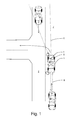
- FIG 1 is a schematic illustration of a motor vehicle 1 comprising a vehicle safety arrangement according to embodiments hereof preparing to turn left at an intersection.
- the vehicle 1 hosting the vehicle safety arrangement has stopped in its lane 7 and the driver or, in the case of an autonomous vehicle, an autonomous travel control arrangement is preparing to turn left.
- the vehicle 1 hosting the arrangement further comprises an Electrical Power Assisted Steering (EPAS) 4 operable to steer one or more wheels 5 of the host vehicle 1.
- EAS Electrical Power Assisted Steering
- the vehicle safety arrangement comprises one or more forward-looking detection systems 6 for detecting oncoming traffic 3 in one or more lanes 2 adjacent to the lane 7 travelled by the host vehicle 1.
- the one or more forward-looking detection systems 6 comprises one or more of a Radio Detection And Ranging (RADAR) sensor, a Light Amplification by Stimulated Emission of Radiation (LASER) sensor, a Light Detection And Ranging (LIDAR) sensor, an ultrasound sensor, an infrared sensor, one or several image sensors, or any combination thereof.
- RADAR Radio Detection And Ranging
- LASER Light Amplification by Stimulated Emission of Radiation
- LIDAR Light Detection And Ranging
- an ultrasound sensor an infrared sensor
- infrared sensor one or several image sensors, or any combination thereof.
- At least one image sensor may be a video sensor, designed as either a Charge-Coupled Device (CCD) camera or a Complementary Metal-Oxide Semiconductor (CMOS) camera, for example. Two or more images sensors may be used for stereo vision.
- CCD Charge-Coupled Device
- CMOS Complementary Metal-Oxide Semiconductor
- the vehicle safety arrangement furthermore comprises one or more rearward-looking detection systems 8 for detecting other vehicles 9 approaching the host vehicle 1 from behind.
- the one or more rearward-looking detection systems 8 comprises one or more of a RADAR sensor, a LASER sensor, a LIDAR sensor, an ultrasound sensor, an infrared sensor, one or several image sensors, or any combination thereof.
- At least one image sensor may here also be a video sensor, designed as either a CCD camera or a CMOS camera, for example. Two or more images sensors may be used for stereo vision.
- the vehicle safety arrangement furthermore comprises one or more turning intention detection systems 10, for determining an intention of a driver of the host vehicle 1 or an autonomous travel control arrangement to turn across an adjacent lane 2.
- Intention to turn across a lane 2 containing oncoming traffic 3 is determined by the one or more turning intention detection systems 10 from one or more parameters indicative of actual vehicle conditions, such as left or right hand steering wheel movement or turning of the steerable wheels 5 of the host vehicle 1 (i.e. steering angular rate), steering angle, information on the extension of the road from at least one of a camera sensor, a map data system and a navigation system such as a GPS system or a fusion of data from any number of suitable sensors, such as those described above..
- parameters indicative of actual vehicle conditions such as left or right hand steering wheel movement or turning of the steerable wheels 5 of the host vehicle 1 (i.e. steering angular rate), steering angle, information on the extension of the road from at least one of a camera sensor, a map data system and a navigation system such as a GPS system or a fusion of data from any number of suitable sensors, such as those described above.
- the vehicle safety arrangement furthermore comprises means for determining standstill 11 of the host vehicle 1.
- the means for determining standstill 11 of the host vehicle 1, i.e. if the host vehicle 1 has stopped, are arranged to determine standstill of the host vehicle 1 from one or several vehicle speed sensors. Alternatively, the vehicle speed may also be obtained from a transmission sensor or from a navigation system such as GPS system or equivalent.
- the vehicle safety arrangement further comprises a control unit 12 arranged to, during determined standstill of the host vehicle 1 and a determined intention to turn across a lane 2 containing oncoming traffic 3, determine a risk of the host vehicle 1 being hit from behind and, upon determining a high risk of the host vehicle 1 being hit from behind, generate and send a control signal to a vehicle EPAS control unit 13, which EPAS control unit 13, in response to receiving such a control signal, is arranged to cause the EPAS 4 to align the steerable wheels 5 of the host vehicle 1 such that any pushing of the vehicle, as a result of the vehicle being hit by another vehicle 9 approaching the host vehicle 1 from behind, only will cause the host vehicle 1 to move in the current lane 7, and thus not into any lane 2 containing oncoming traffic 3.
- a control unit 12 arranged to, during determined standstill of the host vehicle 1 and a determined intention to turn across a lane 2 containing oncoming traffic 3, determine a risk of the host vehicle 1 being hit from behind and, upon determining a high risk of the host vehicle
- the control unit 12 suitably comprises a processing unit, such as a computer processor, and appropriate software for controlling operation thereof.
- control unit 12 is further arranged to determine the risk of the host vehicle 1 being hit from behind based on fused information from two or more sensors of the rearward-looking detection systems 8, which provides for a simple and reliable high quality determination.
- control unit 12 is further arranged to, upon determining the risk of the host vehicle 1 being hit from behind, weight in the risk of the host vehicle 1 being pushed into an adjacent lane 2 containing oncoming traffic 3 if being hit from behind. Weighting in the risk of the host vehicle 1 being pushed into an adjacent lane 2 containing oncoming traffic 3, if being hit from behind by another vehicle 9, provides for a risk determination that accounts also for the consequences of the host vehicle 1 being hit from behind.
- vehicle safety arrangement further comprises means 14 for determining an intention of the vehicle driver or an autonomous travel control arrangement to resume forward travel of the host vehicle 1.
- the control unit 12 is further arranged to release the aligning of the steerable wheels 5 of the host vehicle 1 in response to such intention to resume forward travel being determined. Resumption of intentional forward travel may e.g. be determined from movement of the accelerator pedal or equivalent.
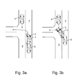
- Figure 3a is a schematic illustration of a prior-art vehicle 1 being struck from behind by another vehicle 9 when preparing to turn left at an intersection.
- the driver of the prior-art vehicle 1 when waiting to make a left turn, has turned the steerable wheels 5 of the prior-art vehicle 1 slightly left.
- Figure 4a is a schematic illustration of a motor vehicle 1 comprising a vehicle safety arrangement according to embodiments hereof being struck from behind by another vehicle 9 when preparing to turn left at an intersection.
- the driver of the host vehicle 1 or an autonomous travel control arrangement when waiting to make a left turn, may or may not have turned the steerable wheels 5 of the host vehicle 1 to the left.
- the vehicle safety arrangement will, during determined standstill of the host vehicle 1 and a determined intention to turn across the lane 2 containing oncoming traffic 3, cause the EPAS 4 to align the steerable wheels 5 of the host vehicle 1 such that any pushing of the vehicle, as a result of the vehicle being hit by the other vehicle 9 approaching the host vehicle 1 from behind, only will cause the host vehicle 1 to move in the current lane 7, and thus not into the lane 2 containing oncoming traffic 3.
- the method comprises the steps of: detecting oncoming traffic 3 in one or more lanes 2 adjacent to the lane 7 travelled by the host vehicle 1 using one or more forward-looking detection systems 6; detecting other vehicles 9 approaching the host vehicle 1 from behind using one or more rearward-looking detection systems 8; determining an intention to turn across an adjacent lane 2 using one or more turning intention detection systems 10; determining standstill of the host vehicle 1 using means for determining standstill 11 of the host vehicle 1; arranging a control unit 12 to, during determined standstill of the host vehicle 1 and a determined intention to turn across a lane 2 containing oncoming traffic 3, determine a risk of the host vehicle 1 being hit from behind; and, upon determining a high risk of the host vehicle 1 being hit from behind, generate and send a control signal to a
- the method ensures that any pushing of the host vehicle 1, as a result of the host vehicle 1 being hit by another vehicle 9 approaching the host vehicle 1 from behind, only will cause the host vehicle 1 to move in the current lane 7, and thus not into any lane 2 containing oncoming traffic 3.
- a motor vehicle 1 that comprises a vehicle safety arrangement for preventing or mitigating accidents when turning across lanes 2 with oncoming traffic 3 in a vehicle 1 hosting the arrangement, the host vehicle 1 further comprising an Electrical Power Assisted Steering 4 operable to steer one or more wheels 5 of the host vehicle 1 as described herein.
Abstract
Description
- Embodiments herein relate to a vehicle safety arrangement for preventing or mitigating accidents when turning across lanes with oncoming traffic in a vehicle hosting the arrangement, the host vehicle further comprising an Electrical Power Assisted Steering operable to steer one or more wheels of the host vehicle.
- Further embodiments herein relate to a method for preventing or mitigating accidents when turning a host vehicle across lanes with oncoming traffic, the host vehicle further comprising an Electrical Power Assisted Steering operable to steer one or more wheels of the host vehicle.
- Still further embodiments herein relate to a motor vehicle comprising a vehicle safety arrangement for preventing or mitigating accidents when turning across lanes with oncoming traffic in a vehicle hosting the arrangement, the host vehicle further comprising an Electrical Power Assisted Steering operable to steer one or more wheels of the host vehicle.
- In right-hand traffic countries the left turn is perhaps the most dangerous of driving maneuvers, simply due to its nature, i.e. you are turning, often from a standstill, across another lane of traffic that's moving in the opposite direction.
- Vehicles turning left into oncoming traffic result in many injuries and even fatalities at intersections. When you turn left, you are crossing one or more lanes of oncoming traffic, presenting your vehicle's broadside to any approaching vehicles. Thus, especially the passenger's side front seat is put into harm's way. If your turning vehicle gets struck, any occupant of the passenger's side front seat takes the most severe impact. Due to the geometry of passenger cars, the protection afforded by the vehicle body against a side impact is usually substantially less than that provided against a front- or rear-end impact.
- Also, it is possible that another vehicle will attempt to overtake you while you are preparing to turn. Thus, your vehicle may get struck by the overtaking vehicle should you proceed with the turning maneuver.
- Furthermore, when waiting to make a left turn drivers sometime tend to turn their wheels slightly left. As a result thereof the vehicle could be pushed into oncoming traffic if accidentally hit from behind by another vehicle.
- In left-hand traffic countries the above applies conversely for right turns.
- Embodiments herein aim to provide an improved vehicle safety arrangement for preventing or mitigating accidents when turning across lanes with oncoming traffic in a vehicle hosting the arrangement, the host vehicle further comprising an Electrical Power Assisted Steering operable to steer one or more wheels of the host vehicle.
- This is provided through the arrangement comprising: one or more forward-looking detection systems for detecting oncoming traffic in one or more lanes adjacent to the lane travelled by the host vehicle; one or more rearward-looking detection systems for detecting other vehicles approaching the host vehicle from behind; one or more turning intention detection systems for determining an intention to turn across an adjacent lane;
means for determining standstill of the host vehicle: a control unit arranged to, during determined standstill of the host vehicle and a determined intention to turn across a lane containing oncoming traffic, determine a risk of the host vehicle being hit from behind; and, upon determining a high risk of the host vehicle being hit from behind, generate and send a control signal to a vehicle Electrical Power Assisted Steering control unit, which Electrical Power Assisted Steering control unit, in response to receiving such a control signal, is arranged to cause the Electrical Power Assisted Steering to align the steerable wheels of the host vehicle. - The provision to align the steerable wheels of the host vehicle during determined standstill of the host vehicle and a determined intention to turn across a lane containing oncoming traffic upon determining a high risk of the host vehicle being hit from behind is ensured that any pushing of the host vehicle as a result of the host vehicle being hit by another vehicle from behind, will only cause the vehicle to move straight forward in the current lane, and thus not turn into a lane containing oncoming traffic and potentially suffer a secondary collision therewith.
- According to a second aspect the one or more forward-looking detection systems comprises one or more of a radar sensor, a laser sensor, a lidar sensor, an ultrasound sensor, an infrared sensor, one or several image sensors, or any combination thereof.
- The provision of a one or more of these sensors provides for facilitates cost efficient realization of the arrangement as determination can be made using sensors that are normally already present in today's vehicles.
- According to a third aspect the one or more rearward-looking detection systems comprises one or more of a radar sensor, a laser sensor, a lidar sensor, an ultrasound sensor, an infrared sensor, one or several image sensors, or any combination thereof.
- The provision of a one or more of these sensors facilitates cost efficient realization of the arrangement as determination can be made using sensors that are normally already present in today's vehicles.
- According to a fourth aspect the one or more turning intention detection systems are arranged to determine an intention to turn across an adjacent lane from one or more parameters, such as left or right hand steering wheel movement, turning of the steerable wheels of the host vehicle, steering angle, information on the extension of the road from at least one of a camera sensor, a map data system and a navigation system.
- The provision of determining an intention to turn across an adjacent lane from one or more of the above parameters facilitates cost efficient realization of the arrangement as determination can be made using sensors that are normally already present in today's vehicles.
- According to a fifth aspect the means for determining standstill are arranged to determine standstill of the host vehicle from at least one of a vehicle speed sensor, two or more vehicle speed sensors, a transmission sensor and a navigation system.
- Determining standstill of the host vehicle in this way is a simple and cost efficient manner using sensors that are normally already present in today's vehicles.
- According to a sixth aspect the control unit further is arranged to determine the risk of the host vehicle being hit from behind based on fused information from two or more sensors of the rearward-looking detection systems.
- Determining the risk of the host vehicle being hit from behind based on fused information from two or more sensors provides for a simple and reliable high quality determination while enabling use of reasonably priced sensors, possibly sensors that are normally already present in today's vehicles.
- According to a seventh aspect the control unit further is arranged to, upon determining the risk of the host vehicle being hit from behind, weight in the risk of the host vehicle being pushed into an adjacent lane containing oncoming traffic if being hit from behind.
- Weighting in the risk of the host vehicle being pushed into an adjacent lane containing oncoming traffic, if being hit from behind, provides for a risk determination that accounts also for the consequences of the host vehicle being hit from behind.
- According to an eight aspect the arrangement further comprises means for determining an intention to resume forward travel of the host vehicle, and in that the control unit further is arranged to release the aligning of the steerable wheels of the host vehicle in response to such intention to resume forward travel being determined.
- Releasing the aligning of the steerable wheels of the host vehicle in response to determining an intention to resume forward travel of the host vehicle enables a driver or an autonomous travel control arrangement to override the vehicle safety arrangement should there for some reason be a need to.
- According to a ninth aspect is further provided a method for preventing or mitigating accidents when turning a host vehicle across lanes with oncoming traffic, the host vehicle further comprising an Electrical Power Assisted Steering operable to steer one or more wheels of the host vehicle, comprising the steps of: detecting oncoming traffic in one or more lanes adjacent to the lane travelled by the host vehicle using one or more forward-looking detection systems; detecting other vehicles approaching the host vehicle from behind using one or more rearward-looking detection systems; determining an intention to turn across an adjacent lane using one or more turning intention detection systems; determining standstill of the host vehicle using means for determining standstill of the host vehicle; arranging a control unit to, during determined standstill of the host vehicle and a determined intention to turn across a lane containing oncoming traffic, determine a risk of the host vehicle being hit from behind; and, upon determining a high risk of the host vehicle being hit from behind, generate and send a control signal to a vehicle Electrical Power Assisted Steering control unit, and arranging the Electrical Power Assisted Steering control unit to, in response to receiving such a control signal, cause the Electrical Power Assisted Steering to align the steerable wheels of the host vehicle.
- Through the provision of a method to align the steerable wheels of the host vehicle during determined standstill of the host vehicle and a determined intention to turn across a lane containing oncoming traffic upon determining a high risk of the host vehicle being hit from behind is ensured that any pushing of the host vehicle as a result of the host vehicle being hit by another vehicle from behind, will only cause the vehicle to move straight forward in the current lane, and thus not turn into a lane containing oncoming traffic and potentially suffer a secondary collision therewith.
- According to a tenth aspect a motor vehicle is provided which comprises a vehicle safety arrangement aligning the steerable wheels of the host vehicle during determined standstill of the host vehicle and a determined intention to turn across a lane containing oncoming traffic upon determining a high risk of the host vehicle being hit from behind, as described herein. A motor vehicle comprising a vehicle safety arrangement as described herein will provide improved safety through ensuring that any pushing of the host vehicle as a result of the host vehicle being hit by another vehicle from behind, will only cause the vehicle to move straight forward in the current lane, and thus not turn into a lane containing oncoming traffic and potentially suffer a secondary collision therewith.
- In the following, embodiments herein will be described in greater detail by way of example only with reference to attached drawings, in which
-
Fig. 1 is a schematic illustration of a motor vehicle comprising a vehicle safety arrangement according to embodiments hereof preparing to turn left at an intersection. -
Fig. 2 is a schematic illustration of a vehicle safety arrangement according to embodiments hereof. -
Fig. 3a is a schematic illustration of a prior-art vehicle being struck from behind by another vehicle when preparing to turn left at an intersection. -
Fig. 3b is a schematic illustration of the prior-art vehicle offigure 3a being pushed into oncoming traffic as a result of being struck from behind by the other vehicle. -
Fig. 4a is a schematic illustration of a motor vehicle comprising a vehicle safety arrangement according to embodiments hereof being struck from behind by another vehicle when preparing to turn left at an intersection. -
Fig. 4b is a schematic illustration of the motor vehicle comprising a vehicle safety arrangement according to embodiments hereof offigure 4a simply being pushed forward in its own lane as a result of being struck from behind by the other vehicle. - Still other objects and features of embodiments herein will become apparent from the following detailed description considered in conjunction with the accompanying drawings. It is to be understood, however, that the drawings are designed solely for purposes of illustration and not as a definition of the limits hereof, for which reference should be made to the appended claims. It should be further understood that the drawings are not necessarily drawn to scale and that, unless otherwise indicated, they are merely intended to conceptually illustrate the structures and procedures described herein.
-
Figure 1 is a schematic illustration of amotor vehicle 1 comprising a vehicle safety arrangement according to embodiments hereof preparing to turn left at an intersection. Thevehicle 1 hosting the vehicle safety arrangement has stopped in its lane 7 and the driver or, in the case of an autonomous vehicle, an autonomous travel control arrangement is preparing to turn left. There is, however,oncoming traffic 3 in theadjacent lane 2, which the vehicle will have to cross in order to reach the connecting road for onward travel. - The vehicle safety arrangement for preventing or mitigating accidents when turning across
lanes 2 withoncoming traffic 3 will be explained in further detail with reference tofigure 2 . - The
vehicle 1 hosting the arrangement further comprises an Electrical Power Assisted Steering (EPAS) 4 operable to steer one ormore wheels 5 of thehost vehicle 1. - The vehicle safety arrangement comprises one or more forward-looking
detection systems 6 for detectingoncoming traffic 3 in one ormore lanes 2 adjacent to the lane 7 travelled by thehost vehicle 1. - In some embodiments hereof the one or more forward-looking
detection systems 6 comprises one or more of a Radio Detection And Ranging (RADAR) sensor, a Light Amplification by Stimulated Emission of Radiation (LASER) sensor, a Light Detection And Ranging (LIDAR) sensor, an ultrasound sensor, an infrared sensor, one or several image sensors, or any combination thereof. - At least one image sensor may be a video sensor, designed as either a Charge-Coupled Device (CCD) camera or a Complementary Metal-Oxide Semiconductor (CMOS) camera, for example. Two or more images sensors may be used for stereo vision.
- The vehicle safety arrangement furthermore comprises one or more rearward-looking
detection systems 8 for detectingother vehicles 9 approaching thehost vehicle 1 from behind. - In some embodiments hereof the one or more rearward-looking
detection systems 8 comprises one or more of a RADAR sensor, a LASER sensor, a LIDAR sensor, an ultrasound sensor, an infrared sensor, one or several image sensors, or any combination thereof. - At least one image sensor may here also be a video sensor, designed as either a CCD camera or a CMOS camera, for example. Two or more images sensors may be used for stereo vision.
- The vehicle safety arrangement furthermore comprises one or more turning
intention detection systems 10, for determining an intention of a driver of thehost vehicle 1 or an autonomous travel control arrangement to turn across anadjacent lane 2. - Intention to turn across a
lane 2 containing oncomingtraffic 3 is determined by the one or more turningintention detection systems 10 from one or more parameters indicative of actual vehicle conditions, such as left or right hand steering wheel movement or turning of thesteerable wheels 5 of the host vehicle 1 (i.e. steering angular rate), steering angle, information on the extension of the road from at least one of a camera sensor, a map data system and a navigation system such as a GPS system or a fusion of data from any number of suitable sensors, such as those described above.. - The vehicle safety arrangement furthermore comprises means for determining
standstill 11 of thehost vehicle 1. The means for determiningstandstill 11 of thehost vehicle 1, i.e. if thehost vehicle 1 has stopped, are arranged to determine standstill of thehost vehicle 1 from one or several vehicle speed sensors. Alternatively, the vehicle speed may also be obtained from a transmission sensor or from a navigation system such as GPS system or equivalent. - The vehicle safety arrangement further comprises a
control unit 12 arranged to, during determined standstill of thehost vehicle 1 and a determined intention to turn across alane 2 containing oncomingtraffic 3, determine a risk of thehost vehicle 1 being hit from behind and, upon determining a high risk of thehost vehicle 1 being hit from behind, generate and send a control signal to a vehicleEPAS control unit 13, whichEPAS control unit 13, in response to receiving such a control signal, is arranged to cause theEPAS 4 to align thesteerable wheels 5 of thehost vehicle 1 such that any pushing of the vehicle, as a result of the vehicle being hit by anothervehicle 9 approaching thehost vehicle 1 from behind, only will cause thehost vehicle 1 to move in the current lane 7, and thus not into anylane 2 containing oncomingtraffic 3. - The
control unit 12 suitably comprises a processing unit, such as a computer processor, and appropriate software for controlling operation thereof. - Also, in some embodiments hereof, the
control unit 12 is further arranged to determine the risk of thehost vehicle 1 being hit from behind based on fused information from two or more sensors of the rearward-lookingdetection systems 8, which provides for a simple and reliable high quality determination. - In further embodiments hereof, the
control unit 12 is further arranged to, upon determining the risk of thehost vehicle 1 being hit from behind, weight in the risk of thehost vehicle 1 being pushed into anadjacent lane 2 containing oncomingtraffic 3 if being hit from behind. Weighting in the risk of thehost vehicle 1 being pushed into anadjacent lane 2 containing oncomingtraffic 3, if being hit from behind by anothervehicle 9, provides for a risk determination that accounts also for the consequences of thehost vehicle 1 being hit from behind. - Also, in embodiments hereof, vehicle safety arrangement further comprises means 14 for determining an intention of the vehicle driver or an autonomous travel control arrangement to resume forward travel of the
host vehicle 1. For this purpose thecontrol unit 12 is further arranged to release the aligning of thesteerable wheels 5 of thehost vehicle 1 in response to such intention to resume forward travel being determined. Resumption of intentional forward travel may e.g. be determined from movement of the accelerator pedal or equivalent. -
Figure 3a is a schematic illustration of a prior-art vehicle 1 being struck from behind by anothervehicle 9 when preparing to turn left at an intersection. Here the driver of the prior-art vehicle 1, when waiting to make a left turn, has turned thesteerable wheels 5 of the prior-art vehicle 1 slightly left. - As a result thereof, as illustrated in
figure 3b , the prior-art vehicle 1 offigure 3a is pushed into theadjacent lane 2 containing oncomingtraffic 3 as a result of accidentally being struck from behind by theother vehicle 9, potentially resulting in a serious accident. -
Figure 4a is a schematic illustration of amotor vehicle 1 comprising a vehicle safety arrangement according to embodiments hereof being struck from behind by anothervehicle 9 when preparing to turn left at an intersection. Here the driver of thehost vehicle 1 or an autonomous travel control arrangement, when waiting to make a left turn, may or may not have turned thesteerable wheels 5 of thehost vehicle 1 to the left. - As illustrated schematically in
figure 4b , the vehicle safety arrangement will, during determined standstill of thehost vehicle 1 and a determined intention to turn across thelane 2 containing oncomingtraffic 3, cause theEPAS 4 to align thesteerable wheels 5 of thehost vehicle 1 such that any pushing of the vehicle, as a result of the vehicle being hit by theother vehicle 9 approaching thehost vehicle 1 from behind, only will cause thehost vehicle 1 to move in the current lane 7, and thus not into thelane 2 containing oncomingtraffic 3. - This will be the case irrespective of if the driver of the
host vehicle 1 or an autonomous travel control arrangement, when waiting to make the left turn, has turned thesteerable wheels 5 of thehost vehicle 1 to the left or not. - According to the present application is also envisaged a method for preventing or mitigating accidents when turning a
host vehicle 1 acrosslanes 2 with oncomingtraffic 3, thehost vehicle 1 further comprising anEPAS 4 operable to steer one ormore wheels 5 of thehost vehicle 1. The method comprises the steps of: detecting oncomingtraffic 3 in one ormore lanes 2 adjacent to the lane 7 travelled by thehost vehicle 1 using one or more forward-lookingdetection systems 6; detectingother vehicles 9 approaching thehost vehicle 1 from behind using one or more rearward-lookingdetection systems 8; determining an intention to turn across anadjacent lane 2 using one or more turningintention detection systems 10; determining standstill of thehost vehicle 1 using means for determiningstandstill 11 of thehost vehicle 1; arranging acontrol unit 12 to, during determined standstill of thehost vehicle 1 and a determined intention to turn across alane 2 containing oncomingtraffic 3, determine a risk of thehost vehicle 1 being hit from behind; and, upon determining a high risk of thehost vehicle 1 being hit from behind, generate and send a control signal to a vehicle Electrical Power AssistedSteering control unit 13, and arranging the Electrical Power AssistedSteering control unit 13 to, in response to receiving such a control signal, cause the Electrical Power AssistedSteering 4 to align thesteerable wheels 5 of thehost vehicle 1. - Thus, the method ensures that any pushing of the
host vehicle 1, as a result of thehost vehicle 1 being hit by anothervehicle 9 approaching thehost vehicle 1 from behind, only will cause thehost vehicle 1 to move in the current lane 7, and thus not into anylane 2 containing oncomingtraffic 3. - The vehicle safety arrangement according to embodiments hereof will, although described above for left turns, work conversely for right turns, which is especially important for left-hand traffic countries.
- Thus, hereby is provided for protecting the
host vehicle 1 and any occupants of thehost vehicle 1 should thehost vehicle 1 suffer a collision from behind when preparing to turn across oncomingtraffic 3. - According to the present application is also envisaged a
motor vehicle 1 that comprises a vehicle safety arrangement for preventing or mitigating accidents when turning acrosslanes 2 with oncomingtraffic 3 in avehicle 1 hosting the arrangement, thehost vehicle 1 further comprising an Electrical Power AssistedSteering 4 operable to steer one ormore wheels 5 of thehost vehicle 1 as described herein. - The above-described embodiments may be varied within the scope of the following claims.
- Thus, while there have been shown and described and pointed out fundamental novel features of the embodiments herein, it will be understood that various omissions and substitutions and changes in the form and details of the devices illustrated, and in their operation, may be made by those skilled in the art. For example, it is expressly intended that all combinations of those elements and/or method steps which perform substantially the same function in substantially the same way to achieve the same results are equivalent. Moreover, it should be recognized that structures and/or elements and/or method steps shown and/or described in connection with any disclosed form or embodiment herein may be incorporated in any other disclosed or described or suggested form or embodiment as a general matter of design choice.
Claims (10)
- A vehicle safety arrangement for preventing or mitigating accidents when turning across lanes (2) with oncoming traffic (3) in a vehicle (1) hosting the arrangement, the host vehicle (1) further comprising an Electrical Power Assisted Steering (4) operable to steer one or more wheels (5) of the host vehicle (1),
characterized in that it comprises:one or more forward-looking detection systems (6) for detecting oncoming traffic (3) in one or more lanes (2) adjacent to the lane (7) travelled by the host vehicle (1);one or more rearward-looking detection systems (8) for detecting other vehicles (9) approaching the host vehicle (1) from behind;one or more turning intention detection systems (10) for determining an intention to turn across an adjacent lane (2);means for determining standstill (11) of the host vehicle (1):a control unit (12) arranged to, during determined standstill of the host vehicle (1) and a determined intention to turn across a lane (2) containing oncoming traffic (3), determine a risk of the host vehicle (1) being hit from behind; and, upon determining a high risk of the host vehicle (1) being hit from behind, generate and send a control signal to a vehicle Electrical Power Assisted Steering control unit (13), which Electrical Power Assisted Steering control unit (13), in response to receiving such a control signal, is arranged to cause the Electrical Power Assisted Steering (4) to align the steerable wheels (5) of the host vehicle (1). - A vehicle safety arrangement according to claim 1, characterized in that the one or more forward-looking detection systems (6) comprises one or more of a radar sensor, a laser sensor, a lidar sensor, an ultrasound sensor, an infrared sensor, one or several image sensors, or any combination thereof.
- A vehicle safety arrangement according to any one of claims 1 to 2, characterized in that the one or more rearward-looking detection systems (8) comprises one or more of a radar sensor, a laser sensor, a lidar sensor, an ultrasound sensor, an infrared sensor, one or several image sensors, or any combination thereof.
- A vehicle safety arrangement according to any one of claims 1 to 3, characterized in that the one or more turning intention detection systems (10) are arranged to determine an intention to turn across an adjacent lane (2) from one or more parameters, such as left or right hand steering wheel movement, turning of the steerable wheels (5) of the host vehicle (1), steering angle, information on the extension of the road from at least one of a camera sensor, a map data system and a navigation system.
- A vehicle safety arrangement according to any one of claims 1 to 4, characterized in that the means for determining standstill (11) are arranged to determine standstill of the host vehicle (1) from at least one of a vehicle speed sensor, two or more vehicle speed sensors, a transmission sensor and a navigation system.
- A vehicle safety arrangement according to claim 3, characterized in that the control unit (12) further is arranged to determine the risk of the host vehicle (1) being hit from behind based on fused information from two or more sensors of the rearward-looking detection systems (8).
- A vehicle safety arrangement according to any one of claims 1 to 6, characterized in that the control unit (12) further is arranged to, upon determining the risk of the host vehicle (1) being hit from behind, weight in the risk of the host vehicle (1) being pushed into an adjacent lane (2) containing oncoming traffic (3) if being hit from behind.
- A vehicle safety arrangement according to any one of claims 1 to 7, characterized in that it further comprises means (14) for determining an intention to resume forward travel of the host vehicle (1), and in that the control unit (12) further is arranged to release the aligning of the steerable wheels (5) of the host vehicle (1) in response to such intention to resume forward travel being determined.
- A method for preventing or mitigating accidents when turning a host vehicle (1) across lanes (2) with oncoming traffic (3), the host vehicle (1) further comprising an Electrical Power Assisted Steering (4) operable to steer one or more wheels (5) of the host vehicle (1), characterized in that it comprises the steps of:detecting oncoming traffic (3) in one or more lanes (2) adjacent to the lane (7) travelled by the host vehicle (1) using one or more forward-looking detection systems (6);detecting other vehicles (9) approaching the host vehicle (1) from behind using one or more rearward-looking detection systems (8);determining an intention to turn across an adjacent lane (2) using one or more turning intention detection systems (10);determining standstill of the host vehicle (1) using means for determining standstill (11) of the host vehicle (1);arranging a control unit (12) to, during determined standstill of the host vehicle (1) and a determined intention to turn across a lane (2) containing oncoming traffic (3), determine a risk of the host vehicle (1) being hit from behind; and, upon determining a high risk of the host vehicle (1) being hit from behind, generate and send a control signal to a vehicle Electrical Power Assisted Steering control unit (13), andarranging the Electrical Power Assisted Steering control unit (13) to, in response to receiving such a control signal, cause the Electrical Power Assisted Steering (4) to align the steerable wheels (5) of the host vehicle (1).
- A motor vehicle (1) characterized in that it comprises a vehicle safety arrangement according to any one of claims 1 to 8.
Priority Applications (3)
| Application Number | Priority Date | Filing Date | Title |
|---|---|---|---|
| EP13169358.2A EP2808217B1 (en) | 2013-05-27 | 2013-05-27 | Vehicle safety arrangement and method |
| US14/280,854 US9349294B2 (en) | 2013-05-27 | 2014-05-19 | Vehicle safety arrangement and method |
| CN201410213449.6A CN104176116B (en) | 2013-05-27 | 2014-05-20 | Vehicle security apparatus and method |
Applications Claiming Priority (1)
| Application Number | Priority Date | Filing Date | Title |
|---|---|---|---|
| EP13169358.2A EP2808217B1 (en) | 2013-05-27 | 2013-05-27 | Vehicle safety arrangement and method |
Publications (2)
| Publication Number | Publication Date |
|---|---|
| EP2808217A1 true EP2808217A1 (en) | 2014-12-03 |
| EP2808217B1 EP2808217B1 (en) | 2019-02-27 |
Family
ID=48578791
Family Applications (1)
| Application Number | Title | Priority Date | Filing Date |
|---|---|---|---|
| EP13169358.2A Active EP2808217B1 (en) | 2013-05-27 | 2013-05-27 | Vehicle safety arrangement and method |
Country Status (3)
| Country | Link |
|---|---|
| US (1) | US9349294B2 (en) |
| EP (1) | EP2808217B1 (en) |
| CN (1) | CN104176116B (en) |
Cited By (3)
| Publication number | Priority date | Publication date | Assignee | Title |
|---|---|---|---|---|
| GB2579025A (en) * | 2018-11-14 | 2020-06-10 | Jaguar Land Rover Ltd | Vehicle control system and method |
| GB2591949A (en) * | 2018-11-14 | 2021-08-11 | Jaguar Land Rover Ltd | Vehicle control system and method |
| US11718138B2 (en) | 2020-01-16 | 2023-08-08 | Honda Motor Co., Ltd. | Motorcycle |
Families Citing this family (18)
| Publication number | Priority date | Publication date | Assignee | Title |
|---|---|---|---|---|
| EP2808217B1 (en) * | 2013-05-27 | 2019-02-27 | Volvo Car Corporation | Vehicle safety arrangement and method |
| US9694777B2 (en) * | 2015-06-11 | 2017-07-04 | GM Global Technology Operations LLC | Wheel assembly adjustment for vehicle events |
| DE102015211133A1 (en) * | 2015-06-17 | 2016-12-22 | Robert Bosch Gmbh | Controlling a motor vehicle |
| CN105365695B (en) * | 2015-08-31 | 2018-03-02 | 珠海上富电技股份有限公司 | Park, blind area and boot open three-in-one detecting system and detection method |
| US10745003B2 (en) | 2015-11-04 | 2020-08-18 | Zoox, Inc. | Resilient safety system for a robotic vehicle |
| US10486707B2 (en) * | 2016-01-06 | 2019-11-26 | GM Global Technology Operations LLC | Prediction of driver intent at intersection |
| US10232848B2 (en) | 2016-01-29 | 2019-03-19 | Toyota Motor Engineering & Manufacturing North America, Inc. | Detection of left turn across path/opposite direction oncoming objects |
| JP6650635B2 (en) * | 2016-02-29 | 2020-02-19 | パナソニックIpマネジメント株式会社 | Determination apparatus, determination method, and determination program |
| US10086830B2 (en) * | 2016-05-23 | 2018-10-02 | Ford Global Technologies, Llc | Accident attenuation systems and methods |
| DE102016216738A1 (en) * | 2016-09-05 | 2018-03-08 | Robert Bosch Gmbh | Method and device for controlling a vehicle |
| KR101899396B1 (en) * | 2016-11-24 | 2018-09-18 | 현대자동차주식회사 | Car and controlling method thereof |
| EP3354525B1 (en) * | 2017-01-26 | 2021-01-13 | Volvo Car Corporation | Arrangement and method for mitigating a forward collision between road vehicles |
| US10338594B2 (en) * | 2017-03-13 | 2019-07-02 | Nio Usa, Inc. | Navigation of autonomous vehicles to enhance safety under one or more fault conditions |
| US10423162B2 (en) | 2017-05-08 | 2019-09-24 | Nio Usa, Inc. | Autonomous vehicle logic to identify permissioned parking relative to multiple classes of restricted parking |
| JP6900775B2 (en) * | 2017-05-12 | 2021-07-07 | 株式会社デンソー | Vehicle automatic driving control system |
| US10369974B2 (en) | 2017-07-14 | 2019-08-06 | Nio Usa, Inc. | Control and coordination of driverless fuel replenishment for autonomous vehicles |
| US10710633B2 (en) | 2017-07-14 | 2020-07-14 | Nio Usa, Inc. | Control of complex parking maneuvers and autonomous fuel replenishment of driverless vehicles |
| US11022971B2 (en) | 2018-01-16 | 2021-06-01 | Nio Usa, Inc. | Event data recordation to identify and resolve anomalies associated with control of driverless vehicles |
Citations (4)
| Publication number | Priority date | Publication date | Assignee | Title |
|---|---|---|---|---|
| DE102005005412A1 (en) * | 2005-02-05 | 2006-08-10 | Volkswagen Ag | Oncoming traffic accident avoiding device for vehicle, has arithmetic and logic unit generating input signal based on signals of sensor, and actuator operated on wheel of vehicle based on input signal |
| US20110054716A1 (en) * | 2008-02-15 | 2011-03-03 | Continental Teves Ag & Co Hg | Vehicle system for navigation and/or driver assistance |
| DE102011108292A1 (en) * | 2011-07-21 | 2012-04-05 | Daimler Ag | Method for operating driver assistance device of vehicle, involves determining scenario-dependent sensor variances or sensor variances depending on driver assistance device in context of error propagation determination |
| WO2013083343A1 (en) * | 2011-12-06 | 2013-06-13 | Robert Bosch Gmbh | Method and system for reducing damage caused by an accident in the event of a collision between two vehicles |
Family Cites Families (18)
| Publication number | Priority date | Publication date | Assignee | Title |
|---|---|---|---|---|
| EP1037760B1 (en) * | 1997-12-15 | 2003-04-02 | Volkswagen Aktiengesellschaft | Method for regulating speed and distance during passing maneuvers |
| US6269308B1 (en) * | 1998-08-20 | 2001-07-31 | Honda Giken Kogyo Kabushiki Kaisha | Safety running system for vehicle |
| JP3174833B2 (en) * | 1999-10-27 | 2001-06-11 | 建設省土木研究所長 | Right turn collision prevention system |
| JP4055656B2 (en) * | 2003-05-30 | 2008-03-05 | トヨタ自動車株式会社 | Collision prediction device |
| JP4421450B2 (en) * | 2004-11-22 | 2010-02-24 | 本田技研工業株式会社 | Vehicle departure determination device |
| JP4463757B2 (en) * | 2005-12-09 | 2010-05-19 | 株式会社小松製作所 | Vehicle travel control device |
| JP4518080B2 (en) * | 2007-01-09 | 2010-08-04 | トヨタ自動車株式会社 | Perimeter monitoring device |
| US8165796B2 (en) * | 2008-09-05 | 2012-04-24 | Robert Bosch Gmbh | Collision avoidance system and method |
| US7991551B2 (en) * | 2008-11-06 | 2011-08-02 | Ford Global Technologies, Llc | System and method for determining a collision status of a nearby vehicle |
| FR2940233B1 (en) * | 2008-12-19 | 2011-01-28 | Jtekt Europe Sas | METHOD FOR DETERMINING THE UNDERGROUND RATE OF A VEHICLE EQUIPPED WITH AN ELECTRIC POWER STEERING, AND POSSIBLE CORRECTION OF THE STEERING ASSISTANCE |
| US20100169016A1 (en) * | 2008-12-29 | 2010-07-01 | Lakshmi Aroop Kodali | Safe side-view system for the driver when over-taking the vehicle in the front on a single lane shared road |
| US8482486B2 (en) * | 2009-04-02 | 2013-07-09 | GM Global Technology Operations LLC | Rear view mirror on full-windshield head-up display |
| US8977489B2 (en) * | 2009-05-18 | 2015-03-10 | GM Global Technology Operations LLC | Turn by turn graphical navigation on full windshield head-up display |
| US9963127B2 (en) * | 2010-01-15 | 2018-05-08 | Volvo Car Corporation | Collision mitigation system and method for braking a vehicle |
| US8527172B2 (en) * | 2010-10-20 | 2013-09-03 | GM Global Technology Operations LLC | Vehicle collision avoidance and warning system |
| DE102010061829A1 (en) * | 2010-11-24 | 2012-05-24 | Continental Teves Ag & Co. Ohg | Method and distance control device for avoiding collisions of a motor vehicle in a driving situation with a small side clearance |
| EP2808217B1 (en) * | 2013-05-27 | 2019-02-27 | Volvo Car Corporation | Vehicle safety arrangement and method |
| KR101509989B1 (en) * | 2013-11-26 | 2015-04-07 | 현대자동차주식회사 | Braking Control System and Method For Vehicle |
-
2013
- 2013-05-27 EP EP13169358.2A patent/EP2808217B1/en active Active
-
2014
- 2014-05-19 US US14/280,854 patent/US9349294B2/en active Active
- 2014-05-20 CN CN201410213449.6A patent/CN104176116B/en active Active
Patent Citations (4)
| Publication number | Priority date | Publication date | Assignee | Title |
|---|---|---|---|---|
| DE102005005412A1 (en) * | 2005-02-05 | 2006-08-10 | Volkswagen Ag | Oncoming traffic accident avoiding device for vehicle, has arithmetic and logic unit generating input signal based on signals of sensor, and actuator operated on wheel of vehicle based on input signal |
| US20110054716A1 (en) * | 2008-02-15 | 2011-03-03 | Continental Teves Ag & Co Hg | Vehicle system for navigation and/or driver assistance |
| DE102011108292A1 (en) * | 2011-07-21 | 2012-04-05 | Daimler Ag | Method for operating driver assistance device of vehicle, involves determining scenario-dependent sensor variances or sensor variances depending on driver assistance device in context of error propagation determination |
| WO2013083343A1 (en) * | 2011-12-06 | 2013-06-13 | Robert Bosch Gmbh | Method and system for reducing damage caused by an accident in the event of a collision between two vehicles |
Non-Patent Citations (1)
| Title |
|---|
| "Verhalten bei drohendem Auffahrunfall - Verkehrstalk Foren", INTERNET CITATION, 10 January 2010 (2010-01-10), pages 1 - 20, XP002690334, Retrieved from the Internet <URL:http://www.verkehrsportal.de/board/index.php?showtopic=81635> [retrieved on 20130115] * |
Cited By (5)
| Publication number | Priority date | Publication date | Assignee | Title |
|---|---|---|---|---|
| GB2579025A (en) * | 2018-11-14 | 2020-06-10 | Jaguar Land Rover Ltd | Vehicle control system and method |
| GB2579025B (en) * | 2018-11-14 | 2021-05-26 | Jaguar Land Rover Ltd | Vehicle control system and method for intention and submission gestures |
| GB2591949A (en) * | 2018-11-14 | 2021-08-11 | Jaguar Land Rover Ltd | Vehicle control system and method |
| GB2591949B (en) * | 2018-11-14 | 2022-04-06 | Jaguar Land Rover Ltd | Vehicle control system and method |
| US11718138B2 (en) | 2020-01-16 | 2023-08-08 | Honda Motor Co., Ltd. | Motorcycle |
Also Published As
| Publication number | Publication date |
|---|---|
| US9349294B2 (en) | 2016-05-24 |
| CN104176116B (en) | 2018-04-13 |
| CN104176116A (en) | 2014-12-03 |
| EP2808217B1 (en) | 2019-02-27 |
| US20140350790A1 (en) | 2014-11-27 |
Similar Documents
| Publication | Publication Date | Title |
|---|---|---|
| US9349294B2 (en) | Vehicle safety arrangement and method | |
| JP6330825B2 (en) | Vehicle collision avoidance support system | |
| US10580303B2 (en) | Collision avoidance device | |
| EP3072770B1 (en) | Autonomous driving device | |
| US10513267B2 (en) | Vehicle safety system | |
| JP6460008B2 (en) | Automatic driving device | |
| JP6252365B2 (en) | Safety confirmation support system, safety confirmation support method | |
| US20200307573A1 (en) | Vehicle control system | |
| JP6536852B2 (en) | Vehicle control apparatus and vehicle control method | |
| CN107472237B (en) | Adaptive cruise control system and vehicle including the same | |
| US10395527B2 (en) | Method and control and detection device for a plausibility check of a wrong-way driving incident of a motor vehicle | |
| JP2019036086A (en) | Vehicle control system and vehicle control method | |
| CN108352117B (en) | Lane maintenance control device | |
| US10882450B2 (en) | Vehicle periphery monitoring apparatus | |
| US20120154135A1 (en) | Advanced Driver Assistance System Having a Sensor Arrangement for Detecting the Distance of the Own Vehicle from a Foreign Object | |
| US10421397B2 (en) | Forward maneuvering assistance using head-up display | |
| US20180268696A1 (en) | Collision avoidance device | |
| EP2484566A1 (en) | Brake assist system | |
| US11338801B2 (en) | Collision avoidance device | |
| JP2018097648A (en) | Vehicle collision avoidance device and vehicle collision avoidance method | |
| EP2923924B1 (en) | Driver assist arrangement | |
| KR102214604B1 (en) | Driving support image display method | |
| US10549777B2 (en) | Control system for steering a tractor vehicle with a trailer | |
| CN111674456A (en) | Method of providing a scene-based overlay torque request signal in a road vehicle steering torque manager | |
| US11220266B2 (en) | Method for at least partially unblocking a field of view of a motor vehicle during lane changes |
Legal Events
| Date | Code | Title | Description |
|---|---|---|---|
| PUAI | Public reference made under article 153(3) epc to a published international application that has entered the european phase |
Free format text: ORIGINAL CODE: 0009012 |
|
| 17P | Request for examination filed |
Effective date: 20130527 |
|
| AK | Designated contracting states |
Kind code of ref document: A1 Designated state(s): AL AT BE BG CH CY CZ DE DK EE ES FI FR GB GR HR HU IE IS IT LI LT LU LV MC MK MT NL NO PL PT RO RS SE SI SK SM TR |
|
| AX | Request for extension of the european patent |
Extension state: BA ME |
|
| R17P | Request for examination filed (corrected) |
Effective date: 20150603 |
|
| RBV | Designated contracting states (corrected) |
Designated state(s): AL AT BE BG CH CY CZ DE DK EE ES FI FR GB GR HR HU IE IS IT LI LT LU LV MC MK MT NL NO PL PT RO RS SE SI SK SM TR |
|
| STAA | Information on the status of an ep patent application or granted ep patent |
Free format text: STATUS: EXAMINATION IS IN PROGRESS |
|
| 17Q | First examination report despatched |
Effective date: 20170713 |
|
| GRAP | Despatch of communication of intention to grant a patent |
Free format text: ORIGINAL CODE: EPIDOSNIGR1 |
|
| STAA | Information on the status of an ep patent application or granted ep patent |
Free format text: STATUS: GRANT OF PATENT IS INTENDED |
|
| INTG | Intention to grant announced |
Effective date: 20180927 |
|
| GRAS | Grant fee paid |
Free format text: ORIGINAL CODE: EPIDOSNIGR3 |
|
| GRAA | (expected) grant |
Free format text: ORIGINAL CODE: 0009210 |
|
| STAA | Information on the status of an ep patent application or granted ep patent |
Free format text: STATUS: THE PATENT HAS BEEN GRANTED |
|
| AK | Designated contracting states |
Kind code of ref document: B1 Designated state(s): AL AT BE BG CH CY CZ DE DK EE ES FI FR GB GR HR HU IE IS IT LI LT LU LV MC MK MT NL NO PL PT RO RS SE SI SK SM TR |
|
| REG | Reference to a national code |
Ref country code: GB Ref legal event code: FG4D |
|
| REG | Reference to a national code |
Ref country code: CH Ref legal event code: EP |
|
| REG | Reference to a national code |
Ref country code: AT Ref legal event code: REF Ref document number: 1100877 Country of ref document: AT Kind code of ref document: T Effective date: 20190315 |
|
| REG | Reference to a national code |
Ref country code: IE Ref legal event code: FG4D |
|
| REG | Reference to a national code |
Ref country code: DE Ref legal event code: R096 Ref document number: 602013051300 Country of ref document: DE |
|
| REG | Reference to a national code |
Ref country code: NL Ref legal event code: MP Effective date: 20190227 |
|
| REG | Reference to a national code |
Ref country code: LT Ref legal event code: MG4D |
|
| PG25 | Lapsed in a contracting state [announced via postgrant information from national office to epo] |
Ref country code: LT Free format text: LAPSE BECAUSE OF FAILURE TO SUBMIT A TRANSLATION OF THE DESCRIPTION OR TO PAY THE FEE WITHIN THE PRESCRIBED TIME-LIMIT Effective date: 20190227 Ref country code: NL Free format text: LAPSE BECAUSE OF FAILURE TO SUBMIT A TRANSLATION OF THE DESCRIPTION OR TO PAY THE FEE WITHIN THE PRESCRIBED TIME-LIMIT Effective date: 20190227 Ref country code: FI Free format text: LAPSE BECAUSE OF FAILURE TO SUBMIT A TRANSLATION OF THE DESCRIPTION OR TO PAY THE FEE WITHIN THE PRESCRIBED TIME-LIMIT Effective date: 20190227 Ref country code: NO Free format text: LAPSE BECAUSE OF FAILURE TO SUBMIT A TRANSLATION OF THE DESCRIPTION OR TO PAY THE FEE WITHIN THE PRESCRIBED TIME-LIMIT Effective date: 20190527 Ref country code: PT Free format text: LAPSE BECAUSE OF FAILURE TO SUBMIT A TRANSLATION OF THE DESCRIPTION OR TO PAY THE FEE WITHIN THE PRESCRIBED TIME-LIMIT Effective date: 20190627 Ref country code: SE Free format text: LAPSE BECAUSE OF FAILURE TO SUBMIT A TRANSLATION OF THE DESCRIPTION OR TO PAY THE FEE WITHIN THE PRESCRIBED TIME-LIMIT Effective date: 20190227 |
|
| PG25 | Lapsed in a contracting state [announced via postgrant information from national office to epo] |
Ref country code: IS Free format text: LAPSE BECAUSE OF FAILURE TO SUBMIT A TRANSLATION OF THE DESCRIPTION OR TO PAY THE FEE WITHIN THE PRESCRIBED TIME-LIMIT Effective date: 20190627 Ref country code: BG Free format text: LAPSE BECAUSE OF FAILURE TO SUBMIT A TRANSLATION OF THE DESCRIPTION OR TO PAY THE FEE WITHIN THE PRESCRIBED TIME-LIMIT Effective date: 20190527 Ref country code: GR Free format text: LAPSE BECAUSE OF FAILURE TO SUBMIT A TRANSLATION OF THE DESCRIPTION OR TO PAY THE FEE WITHIN THE PRESCRIBED TIME-LIMIT Effective date: 20190528 Ref country code: RS Free format text: LAPSE BECAUSE OF FAILURE TO SUBMIT A TRANSLATION OF THE DESCRIPTION OR TO PAY THE FEE WITHIN THE PRESCRIBED TIME-LIMIT Effective date: 20190227 Ref country code: LV Free format text: LAPSE BECAUSE OF FAILURE TO SUBMIT A TRANSLATION OF THE DESCRIPTION OR TO PAY THE FEE WITHIN THE PRESCRIBED TIME-LIMIT Effective date: 20190227 Ref country code: HR Free format text: LAPSE BECAUSE OF FAILURE TO SUBMIT A TRANSLATION OF THE DESCRIPTION OR TO PAY THE FEE WITHIN THE PRESCRIBED TIME-LIMIT Effective date: 20190227 |
|
| REG | Reference to a national code |
Ref country code: AT Ref legal event code: MK05 Ref document number: 1100877 Country of ref document: AT Kind code of ref document: T Effective date: 20190227 |
|
| PG25 | Lapsed in a contracting state [announced via postgrant information from national office to epo] |
Ref country code: CZ Free format text: LAPSE BECAUSE OF FAILURE TO SUBMIT A TRANSLATION OF THE DESCRIPTION OR TO PAY THE FEE WITHIN THE PRESCRIBED TIME-LIMIT Effective date: 20190227 Ref country code: RO Free format text: LAPSE BECAUSE OF FAILURE TO SUBMIT A TRANSLATION OF THE DESCRIPTION OR TO PAY THE FEE WITHIN THE PRESCRIBED TIME-LIMIT Effective date: 20190227 Ref country code: SK Free format text: LAPSE BECAUSE OF FAILURE TO SUBMIT A TRANSLATION OF THE DESCRIPTION OR TO PAY THE FEE WITHIN THE PRESCRIBED TIME-LIMIT Effective date: 20190227 Ref country code: AL Free format text: LAPSE BECAUSE OF FAILURE TO SUBMIT A TRANSLATION OF THE DESCRIPTION OR TO PAY THE FEE WITHIN THE PRESCRIBED TIME-LIMIT Effective date: 20190227 Ref country code: ES Free format text: LAPSE BECAUSE OF FAILURE TO SUBMIT A TRANSLATION OF THE DESCRIPTION OR TO PAY THE FEE WITHIN THE PRESCRIBED TIME-LIMIT Effective date: 20190227 Ref country code: EE Free format text: LAPSE BECAUSE OF FAILURE TO SUBMIT A TRANSLATION OF THE DESCRIPTION OR TO PAY THE FEE WITHIN THE PRESCRIBED TIME-LIMIT Effective date: 20190227 Ref country code: DK Free format text: LAPSE BECAUSE OF FAILURE TO SUBMIT A TRANSLATION OF THE DESCRIPTION OR TO PAY THE FEE WITHIN THE PRESCRIBED TIME-LIMIT Effective date: 20190227 |
|
| REG | Reference to a national code |
Ref country code: DE Ref legal event code: R097 Ref document number: 602013051300 Country of ref document: DE |
|
| PG25 | Lapsed in a contracting state [announced via postgrant information from national office to epo] |
Ref country code: PL Free format text: LAPSE BECAUSE OF FAILURE TO SUBMIT A TRANSLATION OF THE DESCRIPTION OR TO PAY THE FEE WITHIN THE PRESCRIBED TIME-LIMIT Effective date: 20190227 Ref country code: SM Free format text: LAPSE BECAUSE OF FAILURE TO SUBMIT A TRANSLATION OF THE DESCRIPTION OR TO PAY THE FEE WITHIN THE PRESCRIBED TIME-LIMIT Effective date: 20190227 |
|
| REG | Reference to a national code |
Ref country code: CH Ref legal event code: PL |
|
| PG25 | Lapsed in a contracting state [announced via postgrant information from national office to epo] |
Ref country code: AT Free format text: LAPSE BECAUSE OF FAILURE TO SUBMIT A TRANSLATION OF THE DESCRIPTION OR TO PAY THE FEE WITHIN THE PRESCRIBED TIME-LIMIT Effective date: 20190227 |
|
| PLBE | No opposition filed within time limit |
Free format text: ORIGINAL CODE: 0009261 |
|
| STAA | Information on the status of an ep patent application or granted ep patent |
Free format text: STATUS: NO OPPOSITION FILED WITHIN TIME LIMIT |
|
| GBPC | Gb: european patent ceased through non-payment of renewal fee |
Effective date: 20190527 |
|
| PG25 | Lapsed in a contracting state [announced via postgrant information from national office to epo] |
Ref country code: MC Free format text: LAPSE BECAUSE OF FAILURE TO SUBMIT A TRANSLATION OF THE DESCRIPTION OR TO PAY THE FEE WITHIN THE PRESCRIBED TIME-LIMIT Effective date: 20190227 Ref country code: CH Free format text: LAPSE BECAUSE OF NON-PAYMENT OF DUE FEES Effective date: 20190531 Ref country code: LI Free format text: LAPSE BECAUSE OF NON-PAYMENT OF DUE FEES Effective date: 20190531 |
|
| 26N | No opposition filed |
Effective date: 20191128 |
|
| REG | Reference to a national code |
Ref country code: BE Ref legal event code: MM Effective date: 20190531 |
|
| PG25 | Lapsed in a contracting state [announced via postgrant information from national office to epo] |
Ref country code: SI Free format text: LAPSE BECAUSE OF FAILURE TO SUBMIT A TRANSLATION OF THE DESCRIPTION OR TO PAY THE FEE WITHIN THE PRESCRIBED TIME-LIMIT Effective date: 20190227 Ref country code: LU Free format text: LAPSE BECAUSE OF NON-PAYMENT OF DUE FEES Effective date: 20190527 |
|
| PG25 | Lapsed in a contracting state [announced via postgrant information from national office to epo] |
Ref country code: TR Free format text: LAPSE BECAUSE OF FAILURE TO SUBMIT A TRANSLATION OF THE DESCRIPTION OR TO PAY THE FEE WITHIN THE PRESCRIBED TIME-LIMIT Effective date: 20190227 |
|
| PG25 | Lapsed in a contracting state [announced via postgrant information from national office to epo] |
Ref country code: IE Free format text: LAPSE BECAUSE OF NON-PAYMENT OF DUE FEES Effective date: 20190527 Ref country code: GB Free format text: LAPSE BECAUSE OF NON-PAYMENT OF DUE FEES Effective date: 20190527 |
|
| PG25 | Lapsed in a contracting state [announced via postgrant information from national office to epo] |
Ref country code: BE Free format text: LAPSE BECAUSE OF NON-PAYMENT OF DUE FEES Effective date: 20190531 |
|
| PG25 | Lapsed in a contracting state [announced via postgrant information from national office to epo] |
Ref country code: CY Free format text: LAPSE BECAUSE OF FAILURE TO SUBMIT A TRANSLATION OF THE DESCRIPTION OR TO PAY THE FEE WITHIN THE PRESCRIBED TIME-LIMIT Effective date: 20190227 |
|
| PG25 | Lapsed in a contracting state [announced via postgrant information from national office to epo] |
Ref country code: MT Free format text: LAPSE BECAUSE OF FAILURE TO SUBMIT A TRANSLATION OF THE DESCRIPTION OR TO PAY THE FEE WITHIN THE PRESCRIBED TIME-LIMIT Effective date: 20190227 Ref country code: HU Free format text: LAPSE BECAUSE OF FAILURE TO SUBMIT A TRANSLATION OF THE DESCRIPTION OR TO PAY THE FEE WITHIN THE PRESCRIBED TIME-LIMIT; INVALID AB INITIO Effective date: 20130527 |
|
| PG25 | Lapsed in a contracting state [announced via postgrant information from national office to epo] |
Ref country code: MK Free format text: LAPSE BECAUSE OF FAILURE TO SUBMIT A TRANSLATION OF THE DESCRIPTION OR TO PAY THE FEE WITHIN THE PRESCRIBED TIME-LIMIT Effective date: 20190227 |
|
| PGFP | Annual fee paid to national office [announced via postgrant information from national office to epo] |
Ref country code: IT Payment date: 20230420 Year of fee payment: 11 Ref country code: FR Payment date: 20230420 Year of fee payment: 11 Ref country code: DE Payment date: 20230419 Year of fee payment: 11 |
|
| P01 | Opt-out of the competence of the unified patent court (upc) registered |
Effective date: 20231212 |