EP2808211A1 - Leitungssystem für ein Kraftfahrzeug - Google Patents
Leitungssystem für ein Kraftfahrzeug Download PDFInfo
- Publication number
- EP2808211A1 EP2808211A1 EP13005924.9A EP13005924A EP2808211A1 EP 2808211 A1 EP2808211 A1 EP 2808211A1 EP 13005924 A EP13005924 A EP 13005924A EP 2808211 A1 EP2808211 A1 EP 2808211A1
- Authority
- EP
- European Patent Office
- Prior art keywords
- gas
- bypass
- line system
- section
- cooling device
- Prior art date
- Legal status (The legal status is an assumption and is not a legal conclusion. Google has not performed a legal analysis and makes no representation as to the accuracy of the status listed.)
- Granted
Links
Images


Classifications
-
- B—PERFORMING OPERATIONS; TRANSPORTING
- B60—VEHICLES IN GENERAL
- B60T—VEHICLE BRAKE CONTROL SYSTEMS OR PARTS THEREOF; BRAKE CONTROL SYSTEMS OR PARTS THEREOF, IN GENERAL; ARRANGEMENT OF BRAKING ELEMENTS ON VEHICLES IN GENERAL; PORTABLE DEVICES FOR PREVENTING UNWANTED MOVEMENT OF VEHICLES; VEHICLE MODIFICATIONS TO FACILITATE COOLING OF BRAKES
- B60T17/00—Component parts, details, or accessories of power brake systems not covered by groups B60T8/00, B60T13/00 or B60T15/00, or presenting other characteristic features
- B60T17/002—Air treatment devices
- B60T17/004—Draining and drying devices
-
- B—PERFORMING OPERATIONS; TRANSPORTING
- B60—VEHICLES IN GENERAL
- B60T—VEHICLE BRAKE CONTROL SYSTEMS OR PARTS THEREOF; BRAKE CONTROL SYSTEMS OR PARTS THEREOF, IN GENERAL; ARRANGEMENT OF BRAKING ELEMENTS ON VEHICLES IN GENERAL; PORTABLE DEVICES FOR PREVENTING UNWANTED MOVEMENT OF VEHICLES; VEHICLE MODIFICATIONS TO FACILITATE COOLING OF BRAKES
- B60T17/00—Component parts, details, or accessories of power brake systems not covered by groups B60T8/00, B60T13/00 or B60T15/00, or presenting other characteristic features
- B60T17/04—Arrangements of piping, valves in the piping, e.g. cut-off valves, couplings or air hoses
-
- F—MECHANICAL ENGINEERING; LIGHTING; HEATING; WEAPONS; BLASTING
- F04—POSITIVE - DISPLACEMENT MACHINES FOR LIQUIDS; PUMPS FOR LIQUIDS OR ELASTIC FLUIDS
- F04B—POSITIVE-DISPLACEMENT MACHINES FOR LIQUIDS; PUMPS
- F04B39/00—Component parts, details, or accessories, of pumps or pumping systems specially adapted for elastic fluids, not otherwise provided for in, or of interest apart from, groups F04B25/00 - F04B37/00
- F04B39/06—Cooling; Heating; Prevention of freezing
Definitions
- the invention relates to a line system for a motor vehicle, preferably a commercial vehicle.
- the piping system comprises a gas compressor for conveying a gas, a gas dryer for drying the gas and a cooling device, e.g. a cooling coil for cooling the gas.
- pneumatic power brakes In commercial vehicles usually pneumatic power brakes are used because of the large vehicle masses.
- the pneumatic power brake systems work as follows: Air is used in compressed form as stored energy. This energy is then used sporadically when needed for braking the commercial vehicle and thus consumed.
- air By means of various types of air compressors, the energy can be stored continuously or in case of need, eg in compressed air boilers.
- air as an energy source has the disadvantage that moisture is dissolved in the air. This moisture precipitates when condensing the air in the form of condensation. The condensed water must be filtered out of the compressed air, otherwise there is a risk that the power-brake system freezes at temperatures below freezing. Desiccants available on the market only work 100% up to a maximum temperature of about 65 ° C.
- cooling devices for cooling the air are usually designed as coiled tubing.
- the disadvantage of this is that in the coiled tubing, the precipitated water can freeze and the coiled tubing thus grows slowly until the ice ultimately completely closes the coiled tubing.
- the commercial vehicle is then only passable for a very short distance, namely as long as there is still enough energy in the air storage tanks. If the energy is used up, the commercial vehicle can be quasi braked only once with an auxiliary brake device and then no longer be moved.
- An object of the invention is to provide an improved and / or alternative conduit system for a commercial vehicle. This object can be achieved with the features of the independent claim. Advantageous developments of the invention can be taken from the subclaims and the following description.
- the invention provides a conduit system for a commercial vehicle, preferably a truck or a bus.
- the conduit system comprises a gas compressor for conveying a gas, a gas dryer for drying the gas and a cooling device, in particular a cooling coil, for cooling the gas, which is preferably arranged fluidically between the gas compressor and the gas dryer.
- the line system is characterized in particular by the fact that it has a bypass device with a bypass line for the gas, via which the gas can bypass the cooling device expediently be guided directly or indirectly to the gas dryer, preferably if a gas passage through the cooling device is not or only insufficiently possible.
- a gas passage through the cooling device is not or only insufficiently possible, occurs in particular when the cooling device is clogged, in particular frozen.
- bypass means may include valve means (e.g., a flapper and / or pressure relief valve) for properly automatically opening the bypass line when the pressure at the valving input exceeds a predetermined value.
- valve means e.g., a flapper and / or pressure relief valve
- the valve device is preferably normally closed.
- bypass line branches off obliquely and / or at right angles to the regular main flow direction of the gas.
- the bypass line branches off obliquely and / or at right angles from the below-mentioned first section of the bypass device.
- the bypass device comprises a suitably first section with a through-channel.
- the first section and thus its passage is in particular fluidically integrated between the gas compressor and the cooling device in the line system.
- bypass device expediently has a second section with a through-channel.
- the second subsection and thus its passage channel is in particular fluidically integrated between the cooling device and the gas dryer in the line system.
- bypass line it is possible for the bypass line to extend between the through-passage of the first section and the through-channel of the second section and, in particular off-center, branches off from the through-passage of the first section and / or off-center into the through-channel of the second section.
- the bypass line has a flow cross section which is smaller than the flow cross section of the passage channel of the first section and / or the second section.
- the bypass device is preferably designed so that a full amount of gas can flow over the bypass device at maximum speed of the gas compressor when the gas passage through the cooling device, in particular the cooling device, is clogged, and / or a negligible amount of gas (eg less than 15%). less than 10% or even less than 5% of the total amount of gas delivered by the gaspressor) can flow via the bypass device if the gas passage through the cooling device, in particular the cooling device, is free from blockage and thus can be operated properly.
- the bypass device can thus be provided on the one hand with an openable valve device.
- the bypass device can generate a valve function by predefined flow conditions. In both cases, in particular, no or only very small amounts of gas can pass through the bypass device, while in the event of a malfunction (for example blockage of the cooling device), the gas can pass through the bypass device in a sufficient amount to the gas dryer.
- the first subsection may have a connection configuration (eg a thread configuration) by means of which it is fluidically integrated between the gas presser and the cooling device in the line system.
- the second subsection may have a connection configuration (eg a thread configuration) by means of which it is fluidically integrated between the cooling device and the gas dryer in the line system.
- the bypass device in particular its first section, can be arranged fluidically immediately before the cooling device and / or mounted on the cooling device.
- the bypass device in particular its second subsection, can be arranged fluidically immediately behind the cooling device and / or mounted on the cooling device.
- bypass device is designed as a fitting part and e.g. the bypass line and preferably the first section and / or the second section is at least partially integrated into the fitting part.
- the bypass line can be designed at least in sections as a conduit or conduit hose and, for example, open directly into the gas dryer.
- the gas dryer is suitably connected to a gas consumer in order to supply the gas consumer with gas.
- the gas consumer is preferably a power brake system for the commercial vehicle.
- the medium gas is preferably air.
- the invention is not limited to a conduit system but also includes a utility vehicle, e.g. a truck or omnibus, with a conduit system as described herein.
- a utility vehicle e.g. a truck or omnibus
- FIG. 1 shows a schematic view of a conduit system 1 for a commercial vehicle, in particular a truck or a bus.
- the piping system 1 comprises a gas compressor 2 for conveying a gas, a gas dryer 3 for drying the gas and a cooling device 4, in particular a cooling coil, for cooling the gas.
- the cooling device 4 is arranged fluidically between the gas compressor 2 and the gas dryer 3.
- the line system 1 comprises fluidically behind the gas dryer 3 at least one not shown, to be supplied with the dried gas gas consumers.
- the line system 1 also comprises a bypass device B with a bypass line L for the gas, via the gas bypassing the cooling device 4 to the gas dryer 3 is feasible if a gas passage GP on the cooling device 4 is not or only insufficiently possible, which is particularly the Case is when the cooling device 4 is at least partially blocked, in particular at least partially frozen.
- the bypass line L branches off from a line section of the line system 1, which extends fluidically between the gas compressor 2 and the cooling device 4, and flows into a line section extending fluidically between the cooling device 4 and the gas dryer 3 of the line system 1.
- the bypass line also open directly into the gas dryer 3, as in FIG. 1 schematically indicated by the dashed arrow (L).
- the bypass device B has a movable valve device, not shown in detail, which is normally closed, ie when a sufficient gas passage GP is possible via the cooling device 4, and only then opens automatically when the pressure at the valve device input exceeds a predetermined value.
- the pressure applied to the valve device inlet increases when part of the gas passage GP, in particular the cooling device 4, gradually freezes and becomes clogged.
- the valve device can be designed as a per se conventional flap and / or pressure relief valve.
- FIG. 2 shows a perspective view of a portion of a conduit system 1 according to another embodiment of the invention.
- the bypass device B is designed as a fitting part and comprises a first section T1 and a second section T2.
- the bypass device B, in particular the first section T1 is fluidically arranged immediately in front of the cooling device 4 and mounted on the cooling device 4.
- the bypass device B, in particular the second section T2 is fluidly arranged immediately behind the cooling device 4 and mounted on the cooling device 4.
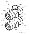
- FIG. 3 shows a perspective view of a bypass device B according to yet another embodiment of the invention
- FIG. 4 a cross-sectional view of the bypass device B from FIG. 3 shows.
- the bypass device B comprises a first section T1 with a passage K1.
- the first section T1 and thus the passage K1 is fluidically to be integrated between the gas compressor 2 and the cooling device 4 in the line system 1.
- the bypass device B also includes a second section T2 with a passage K2.
- the second section T2 and thus the passage K2 is fluidically to integrate between the cooling device 4 and the gas dryer 3 in the line system 1.
- the bypass line L connects the passage K1 with the passage K2.
- the first subsection T1 includes a port configuration A1 and A2.
- the connection configuration A1 is used to connect the first section T1 on the input side with a conduit or a conduit of the conduit system 1, while the connection configuration A2 serves to connect the first section T1 on the output side to the cooling device 4.
- the connection configuration A2 can serve to connect the first subsection T1 on the output side to a conduit or a conduit of the conduit system 1.
- the second section T2 includes a connection configuration A3 and A4.
- the connection configuration A3 serves to connect the second subsection T2 on the input side to the cooling device 4, while the connection configuration A4 serves to connect the second subsection T2 on the output side to a conduit or a conduit of the conduit system 1.
- the connection configuration A3 can serve to connect the second subsection T2 on the input side to a conduit or a conduit of the conduit system 1.
- the bypass line L is arranged so that it branches off substantially at right angles to the passage K1 and / or substantially perpendicular to the regular main flow direction SR of the gas, which is schematically indicated by the arrow BR.
- the bypass line L is further designed so that it branches off eccentrically offset from the passage K1 of the first section T1 and preferably eccentrically offset in the passage K2 of the second section T2 opens.
- the flow cross section of the bypass line L is smaller than the flow cross section of the passage K1 and preferably smaller than the flow cross section of the passage K2.
- the bypass device B of Figures 3 and 4 does not include a movable valve device as with reference to FIGS FIG. 1 mentioned, but creates an intelligent flow ratio.
- the bypass device B is on the one hand designed so that a full amount of gas at maximum speed of the gas compressor 2, the bypass device B can happen when the gas passage GP, in particular the cooling device 4 is completely blocked.
- the bypass device B is designed such that only a negligible amount of gas, eg less than 10% of the total gas quantity delivered by the gas compressor 2, can pass through the bypass device B if the gas passage GP, in particular the cooling device 4, is operated in the normal state and thus at least substantially is blockage free.
- the bypass device B of Figures 3 and 4 is designed as a fitting part, in which the bypass line L is integrated.
- the bypass line L for example, at least partially extends in a fitting part and / or is at least partially designed as a conduit or conduit hose, and for example as in FIG. 1 indicated by the dashed arrow (L) directly into the gas dryer 3 opens.
- the above-described embodiments have been described with reference to the medium of gas.
- the medium gas is preferably air.
Landscapes
- Engineering & Computer Science (AREA)
- Mechanical Engineering (AREA)
- Transportation (AREA)
- General Engineering & Computer Science (AREA)
- Pipeline Systems (AREA)
- Compressor (AREA)
- Valves And Accessory Devices For Braking Systems (AREA)
- Motor Or Generator Cooling System (AREA)
- Drying Of Solid Materials (AREA)
Abstract
Description
- Die Erfindung betrifft ein Leitungssystem für ein Kraftfahrzeug, vorzugsweise ein Nutzfahrzeug. Das Leitungssystem umfasst einen Gaspresser zur Beförderung eines Gases, einen Gastrockner zum Trocknen des Gases und eine Kühleinrichtung, z.B. eine Kühlwendel, zum Kühlen des Gases.
- Bei Nutzfahrzeugen werden wegen der großen Fahrzeugmassen üblicherweise pneumatische Fremdkraftbremsanlagen eingesetzt. Die pneumatischen Fremdkraftbremsanlagen funktionieren wie folgt: Luft wird in verdichteter Form als gespeicherte Energie genutzt. Diese Energie wird dann im Bedarfsfall sporadisch für Bremsungen des Nutzfahrzeugs verwendet und somit verbraucht. Mittels verschiedensten Bauarten von Luftpressern kann die Energie kontinuierlich oder im Bedarfsfall wieder gespeichert werden, z.B. in Druckluftkesseln. Luft als Energieträger hat jedoch den Nachteil, dass in der Luft Feuchtigkeit gelöst ist. Diese Feuchtigkeit fällt bei Verdichtung der Luft in Form von Kondenswasser aus. Das Kondenswasser muss aus der verdichteten Luft herausgefiltert werden, da andernfalls die Gefahr besteht, dass die Fremdkraftbremsanlage bei Temperaturen unter dem Gefrierpunkt einfriert. Am Markt verfügbare Trockenmittel arbeiten nur bis zu einer maximalen Temperatur von ungefähr 65 °C zu 100 %. Bei höheren Temperaturen sinkt die Trockenleistung exponentiell. Da sich die Luft bei der Verdichtung erwärmt, muss sie vor einem Lufttrockner gekühlt werden. Bei der Kühlung der Luft fällt zusätzlich Kondenswasser aus. Aus Package- und Kostengründen werden Kühleinrichtungen zur Kühlung der Luft meist als Rohrwendel ausgeführt. Nachteilhaft daran ist, dass in der Rohrwendel das ausgefallene Wasser gefrieren kann und die Rohrwendel somit langsam zuwächst, bis das Eis die Rohrwendel letztendlich ganz verschließt. Das Nutzfahrzeug ist daraufhin nur mehr für eine sehr kurze Strecke befahrbar, nämlich so lange, wie noch genügend Energie in den Luft-Vorratsbehältern vorhanden ist. Ist die Energie aufgebraucht, kann das Nutzfahrzeug quasi nur noch einmal mit einer Hilfsbremseinrichtung gebremst werden und anschließend nicht mehr bewegt werden.
- Eine Aufgabe der Erfindung ist es, ein verbessertes und/oder alternatives Leitungssystem für ein Nutzfahrzeug zu schaffen. Diese Aufgabe kann mit den Merkmalen des unabhängigen Anspruchs gelöst werden. Vorteilhafte Weiterbildungen der Erfindung sind den Unteransprüchen und der nachfolgenden Beschreibung zu entnehmen.
- Die Erfindung schafft ein Leitungssystem für ein Nutzfahrzeug, vorzugsweise einen Lastkraftwagen oder einen Omnibus. Das Leitungssystem umfasst einen Gaspresser zur Beförderung eines Gases, einen Gastrockner zum Trocknen des Gases und eine Kühleinrichtung, insbesondere eine Kühlwendel, zum Kühlen des Gases, die vorzugsweise strömungstechnisch zwischen dem Gaspresser und dem Gastrockner angeordnet ist. Das Leitungssystem zeichnet sich insbesondere dadurch aus, dass es eine Bypasseinrichtung mit einer Bypassleitung für das Gas aufweist, über die das Gas unter Umgehung der Kühleinrichtung zweckmäßig mittelbar oder unmittelbar zu dem Gastrockner geführt werden kann, vorzugsweise dann, wenn eine Gaspassage über die Kühleinrichtung nicht oder nur unzureichend möglich ist. Der Fall, dass eine Gaspassage über die Kühleinrichtung nicht oder nur unzureichend möglich ist, tritt insbesondere dann auf, wenn die Kühleinrichtung verstopft, insbesondere zugefroren ist.
- Es ist möglich, dass die Bypasseinrichtung eine Ventileinrichtung (z.B. ein Klappenund/oder Überdruckventil) zum zweckmäßig selbsttätigen Öffnen der Bypassleitung aufweist, wenn der am Ventileinrichtungs-Eingang anstehende Druck einen vorbestimmten Wert übersteigt. Der am Ventileinrichtungs-Eingang anstehende Druck steigt z.B., wenn die Kühleinrichtung zunehmend zugefriert. Die Ventileinrichtung ist vorzugsweise im Normalfall geschlossen.
- Es ist möglich, dass die Bypassleitung schräg und/oder rechtwinklig zur regulären Hauptströmungsrichtung des Gases abzweigt. Vorzugsweise zweigt die Bypassleitung schräg und/oder rechtwinklig von dem nachfolgend erwähnten ersten Teilabschnitt der Bypasseinrichtung ab.
- Die Bypasseinrichtung umfasst einen zweckmäßig ersten Teilabschnitt mit einem Durchgangskanal. Der erste Teilabschnitt und somit dessen Durchgangskanal ist insbesondere strömungstechnisch zwischen dem Gaspresser und der Kühleinrichtung in das Leitungssystem integriert.
- Es ist möglich, dass die Bypasseinrichtung zweckmäßig einen zweiten Teilabschnitt mit einem Durchgangskanal aufweist. Der zweite Teilabschnitt und somit dessen Durchgangskanal ist insbesondere strömungstechnisch zwischen der Kühleinrichtung und dem Gastrockner in das Leitungssystem integriert.
- Es ist möglich, dass die Bypassleitung sich zwischen dem Durchgangskanal des ersten Teilabschnitts und dem Durchgangskanal des zweiten Teilabschnitts erstreckt und insbesondere außermittig versetzt von dem Durchgangskanal des ersten Teilabschnitts abzweigt und/oder außermittig versetzt in den Durchgangskanal des zweiten Teilabschnitts mündet.
- Die Bypassleitung umfasst einen Strömungsquerschnitt, der kleiner ist als der Strömungsquerschnitt des Durchgangskanals des ersten Teilabschnitts und/oder des zweiten Teilabschnitts.
- Die Bypasseinrichtung ist vorzugsweise so ausgeführt, dass eine volle Gasmenge bei maximaler Drehzahl des Gaspressers über die Bypasseinrichtung strömen kann, wenn die Gaspassage über die Kühleinrichtung, insbesondere die Kühleinrichtung, verstopft ist, und/oder eine nur vernachlässigbare Gasmenge (z.B. weniger als 15%, weniger als 10% oder sogar weniger als 5% der vom Gaspresser geförderten Gesamtgasmenge) über die Bypasseinrichtung strömen kann, wenn die Gaspassage über die Kühleinrichtung, insbesondere die Kühleinrichtung, verstopfungsfrei ist und somit zweckmäßig regulär betrieben werden kann.
- Die Bypasseinrichtung kann somit einerseits mit einer öffenbaren Ventileinrichtung versehen sein. Ebenso kann die Bypasseinrichtung durch vordefinierte Strömungsverhältnisse eine Ventilfunktion erzeugen. Für beide Fälle gilt insbesondere, dass im Normalfall keine oder nur sehr geringe Gasmengen die Bypasseinrichtung passieren können, während im Störungsfall (z.B. einer Verstopfung der Kühleinrichtung) das Gas in ausreichender Menge die Bypasseinrichtung hin zum Gastrockner passieren kann.
- Es ist möglich, dass der erste Teilabschnitt eine Anschlusskonfiguration (z.B. eine Gewindekonfiguration) aufweist, mittels der er strömungstechnisch zwischen den Gaspresser und die Kühleinrichtung in das Leitungssystem integriert ist. Alternativ oder ergänzend kann der zweite Teilabschnitt eine Anschlusskonfiguration (z.B. eine Gewindekonfiguration) aufweisen, mittels der er strömungstechnisch zwischen die Kühleinrichtung und den Gastrockner in das Leitungssystem integriert ist.
- Die Bypasseinrichtung, insbesondere deren erster Teilabschnitt, kann strömungstechnisch unmittelbar vor der Kühleinrichtung angeordnet sein und/oder an der Kühleinrichtung montiert sein. Ebenso kann die Bypasseinrichtung, insbesondere deren zweiter Teilabschnitt, strömungstechnisch unmittelbar hinter der Kühleinrichtung angeordnet sein und/oder an der Kühleinrichtung montiert sein.
- Es ist möglich, dass die Bypasseinrichtung als Armaturenteil ausgeführt ist und z.B. die Bypassleitung und vorzugsweise der erste Teilabschnitt und/oder der zweite Teilabschnitt zumindest abschnittsweise in das Armaturenteil integriert ist. Alternativ oder ergänzend kann die Bypassleitung zumindest abschnittsweise als Leitungsrohr oder Leitungsschlauch ausgeführt sein und z.B. direkt in den Gastrockner münden.
- Der Gastrockner ist zweckmäßig mit einem Gasverbraucher verbunden, um den Gasverbraucher mit Gas zu versorgen. Der Gasverbraucher ist vorzugsweise eine Fremdkraftbremsanlage für das Nutzfahrzeug.
- Zu erwähnen ist, dass im Rahmen der Erfindung das Merkmal "verstopft" bzw. "zugefroren" sich nicht zwangsläufig auf eine komplette Verstopfung eines Strömungsquerschnitts beziehen muss, sondern sich auch auf einen nur reduzierten Strömungsquerschnitt und somit zweckmäßig eine nur teilweise Verstopfung beziehen kann.
- Zu erwähnen ist ferner, dass das Medium Gas vorzugsweise Luft ist.
- Die Erfindung ist nicht auf ein Leitungssystem beschränkt, sondern umfasst ferner ein Nutzfahrzeug, z.B. einen Lastkraftwagen oder einen Omnibus, mit einem Leitungssystem wie hierin beschrieben.
- Die oben beschriebenen Ausführungsformen der Erfindung sind beliebig miteinander kombinierbar. Andere vorteilhafte Weiterbildungen der Erfindung sind in den Unteransprüchen offenbart oder ergeben sich aus der folgenden Beschreibung bevorzugter Ausführungen der Erfindung in Verbindung mit den beigefügten Figuren.
- Figur 1
- zeigt eine schematische Ansicht eines Leitungssystems für ein Nutzfahrzeug gemäß einer Ausführungsform der Erfindung,
- Figur 2
- zeigt eine perspektivische Ansicht eines Teilbereichs eines Leitungssystems gemäß einer anderen Ausführungsform der Erfindung,
- Figur 3
- zeigt eine perspektivische Ansicht einer Bypasseinrichtung gemäß einer Ausführungsform der Erfindung und
- Figur 4
- zeigt eine Querschnittsansicht der Bypasseinrichtung aus
Figur 3 . - Die in den Figuren gezeigten Ausführungsformen stimmen teilweise überein, wobei ähnliche oder identische Teile mit den gleichen Bezugszeichen versehen sind, und zu deren Erläuterung auch auf die Beschreibung anderer Ausführungsformen verwiesen wird, um Wiederholungen zu vermeiden.
-
Figur 1 zeigt eine schematische Ansicht eines Leitungssystems 1 für ein Nutzfahrzeug, insbesondere einen Lastkraftwagen oder einen Omnibus. Das Leitungssystem 1 umfasst einen Gaspresser 2 zur Beförderung eines Gases, einen Gastrockner 3 zum Trocknen des Gases und eine Kühleinrichtung 4, insbesondere eine Kühlwendel, zum Kühlen des Gases. Die Kühleinrichtung 4 ist strömungstechnisch zwischen dem Gaspresser 2 und dem Gastrockner 3 angeordnet. Das Leitungssystem 1 umfasst strömungstechnisch hinter dem Gastrockner 3 noch zumindest einen nicht gezeigten, mit dem getrockneten Gas zu versorgenden Gasverbraucher. - Das Leitungssystem 1 umfasst zudem eine Bypasseinrichtung B mit einer Bypassleitung L für das Gas, über die Gas unter Umgehung der Kühleinrichtung 4 zu dem Gastrockner 3 führbar ist, wenn eine Gaspassage GP über die Kühleinrichtung 4 nicht oder nur unzureichend möglich ist, was insbesondere dann der Fall ist, wenn die Kühleinrichtung 4 zumindest teilweise verstopft, insbesondere zumindest teilweise zugefroren ist.
- In dem in
Figur 1 gezeigten Ausführungsbeispiel zweigt die Bypassleitung L von einem sich strömungstechnisch zwischen dem Gaspresser 2 und der Kühleinrichtung 4 erstrekkenden Leitungsabschnitt des Leitungssystems 1 ab und mündet in einen sich strömungstechnisch zwischen der Kühleinrichtung 4 und dem Gastrockner 3 erstreckenden Leitungsabschnitt des Leitungssystems 1. Alternativ kann die Bypassleitung auch direkt in den Gastrockner 3 münden, wie inFigur 1 schematisch durch den gestrichelten Pfeil (L) angedeutet ist. Die Bypasseinrichtung B weist eine nicht näher gezeigte bewegliche Ventileinrichtung auf, die im Normalfall - also wenn eine ausreichende Gaspassage GP über die Kühleinrichtung 4 möglich ist - geschlossen ist und erst dann selbsttätig öffnet, wenn der am Ventileinrichtungs-Eingang anstehende Druck einen vorbestimmten Wert übersteigt. Der am Ventileinrichtungs-Eingang anstehende Druck steigt, wenn ein Teil der Gaspassage GP, insbesondere die Kühleinrichtung 4 allmählich zugefriert und somit verstopft. Die Ventileinrichtung kann als an sich herkömmliches Klappen- und/oder Überdruckventil ausgeführt sein. -
Figur 2 zeigt eine perspektivische Ansicht eines Teilbereichs eines Leitungssystems 1 gemäß einer anderen Ausführungsform der Erfindung. Die Bypasseinrichtung B ist als Armaturenteil ausgeführt und umfasst einen ersten Teilabschnitt T1 und einen zweiten Teilabschnitt T2. Die Bypasseinrichtung B, insbesondere der erste Teilabschnitt T1 ist strömungstechnisch unmittelbar vor der Kühleinrichtung 4 angeordnet und an der Kühleinrichtung 4 montiert. Die Bypasseinrichtung B, insbesondere der zweite Teilabschnitt T2 ist strömungstechnisch unmittelbar hinter der Kühleinrichtung 4 angeordnet und an der Kühleinrichtung 4 montiert. -
Figur 3 zeigt eine perspektivische Ansicht einer Bypasseinrichtung B gemäß einer wiederum anderen Ausführungsform der Erfindung, währendFigur 4 eine Querschnittsansicht der Bypasseinrichtung B ausFigur 3 zeigt. Unter Bezugnahme auf dieFiguren 3 und4 umfasst die Bypasseinrichtung B einen ersten Teilabschnitt T1 mit einem Durchgangskanal K1. Der erste Teilabschnitt T1 und somit der Durchgangskanal K1 ist strömungstechnisch zwischen den Gaspresser 2 und die Kühleinrichtung 4 in das Leitungssystem 1 zu integrieren. Die Bypasseinrichtung B umfasst zudem einen zweiten Teilabschnitt T2 mit einem Durchgangskanal K2. Der zweite Teilabschnitt T2 und somit der Durchgangskanal K2 ist strömungstechnisch zwischen die Kühleinrichtung 4 und den Gastrockner 3 in das Leitungssystem 1 zu integrieren. Die Bypassleitung L verbindet den Durchgangskanal K1 mit dem Durchgangskanal K2. - Der erste Teilabschnitt T1 umfasst eine Anschlusskonfiguration A1 und A2. Die Anschlusskonfiguration A1 dient dazu, den ersten Teilabschnitt T1 eingangsseitig mit einem Leitungsrohr oder einem Leitungsschlauch des Leitungssystems 1 zu verbinden, während die Anschlusskonfiguration A2 dazu dient, den ersten Teilabschnitt T1 ausgangsseitig mit der Kühleinrichtung 4 zu verbinden. Alternativ kann die Anschlusskonfiguration A2 dazu dienen, den ersten Teilabschnitt T1 ausgangsseitig mit einem Leitungsrohr oder einem Leitungsschlauch des Leitungssystems 1 zu verbinden.
- Der zweite Teilabschnitt T2 umfasst eine Anschlusskonfiguration A3 und A4. Die Anschlusskonfiguration A3 dient dazu, den zweiten Teilabschnitt T2 eingangsseitig mit der Kühleinrichtung 4 zu verbinden, während die Anschlusskonfiguration A4 dazu dient, den zweiten Teilabschnitt T2 ausgangsseitig mit einem Leitungsrohr oder einem Leitungsschlauch des Leitungssystems 1 zu verbinden. Alternativ kann die Anschlusskonfiguration A3 dazu dienen, den zweiten Teilabschnitt T2 eingangsseitig mit einem Leitungsrohr oder einem Leitungsschlauch des Leitungssystems 1 zu verbinden.
- Die Bypassleitung L ist so angeordnet, dass sie im Wesentlichen rechtwinklig zum Durchgangskanal K1 und/oder im Wesentlichen rechtwinklig zur regulären Hauptströmungsrichtung SR des Gases abzweigt, was durch den Pfeil BR schematisch angedeutet ist.
- Die Bypassleitung L ist ferner so ausgeführt, dass sie außermittig versetzt von dem Durchgangskanal K1 des ersten Teilabschnitts T1 abzweigt und vorzugsweise außermittig versetzt in den Durchgangskanal K2 des zweiten Teilabschnitts T2 mündet. Der Strömungsquerschnitt der Bypassleitung L ist kleiner als der Strömungsquerschnitt des Durchgangskanals K1 und vorzugsweise kleiner als der Strömungsquerschnitt des Durchgangskanals K2.
- Die Bypasseinrichtung B der
Figuren 3 und4 umfasst keine bewegliche Ventileinrichtung wie unter Bezugnahme auf dieFigur 1 erwähnt, sondern erzeugt ein intelligentes Strömungsverhältnis. Die Bypasseinrichtung B ist einerseits so ausgeführt, dass eine volle Gasmenge bei maximaler Drehzahl des Gaspressers 2 die Bypasseinrichtung B passieren kann, wenn die Gaspassage GP, insbesondere die Kühleinrichtung 4 vollständig blokkiert ist. Die Bypasseinrichtung B ist andererseits so ausgeführt, dass nur eine vernachlässigbare Gasmenge, z.B. weniger als 10% der vom Gaspresser 2 geförderten Gesamtgasmenge, die Bypasseinrichtung B passieren kann, wenn die Gaspassage GP, insbesondere die Kühleinrichtung 4 im Normalzustand betrieben wird und somit zumindest im Wesentlichen verstopfungsfrei ist. - Die Bypasseinrichtung B der
Figuren 3 und4 ist als Armaturenteil ausgeführt, in das die Bypassleitung L integriert ist. Es sind allerdings Ausführungsformen möglich, bei denen die Bypassleitung L z.B. zumindest teilweise in einem Armaturenteil verläuft und/oder zumindest teilweise als Leitungsrohr oder Leitungsschlauch ausgeführt ist, und z.B. wie inFigur 1 durch den gestrichelten Pfeil (L) angedeutet direkt in den Gastrockner 3 mündet. - Die zuvor beschriebenen Ausführungsformen wurden unter Bezugnahme auf das Medium Gas beschrieben. Das Medium Gas ist vorzugsweise Luft.
- Die Erfindung ist nicht auf die oben beschriebenen bevorzugten Ausführungsformen beschränkt. Vielmehr ist eine Vielzahl von Varianten und Abwandlungen möglich, die ebenfalls von dem Erfindungsgedanken Gebrauch machen und deshalb in den Schutzbereich fallen. Darüber hinaus beansprucht die Erfindung auch Schutz für den Gegenstand und die Merkmale der Unteransprüche unabhängig von den in Bezug genommenen Merkmalen und Ansprüchen.
Claims (16)
- Leitungssystem (1) für ein Kraftfahrzeug, vorzugsweise Nutzfahrzeug, mit:- einem Gaspresser (2) zur Beförderung eines Gases,- einem Gastrockner (3) zum Trocknen des Gases und- einer Kühleinrichtung (4), insbesondere einer Kühlwendel, zum Kühlen des Gases, dadurch gekennzeichnet, dass- das Leitungssystem (1) eine Bypasseinrichtung (B) mit einer Bypassleitung (L) für das Gas aufweist, über die das Gas unter Umgehung der Kühleinrichtung (4) zu dem Gastrockner (3) führbar ist.
- Leitungssystem (1) nach Anspruch 1, dadurch gekennzeichnet, dass die Bypasseinrichtung (B) eine Ventileinrichtung zum vorzugsweise selbsttätigen Öffnen der Bypassleitung (L) aufweist, wenn der am Ventileinrichtungs-Eingang anstehende Druck einen vorbestimmten Wert übersteigt.
- Leitungssystem (1) nach Anspruch 1 oder 2, dadurch gekennzeichnet, dass die Bypassleitung (L) zur regulären Hauptströmungsrichtung (SR) des Gases schräg und/oder rechtwinklig abzweigt (BR).
- Leitungssystem (1) nach einem der vorhergehenden Ansprüche, dadurch gekennzeichnet, dass die Bypasseinrichtung (B) einen ersten Teilabschnitt (T1) mit einem Durchgangskanal (K1) aufweist, der vorzugsweise strömungstechnisch zwischen dem Gaspresser (2) und der Kühleinrichtung (4) angeordnet ist.
- Leitungssystem (1) nach einem der vorhergehenden Ansprüche, dadurch gekennzeichnet, dass die Bypasseinrichtung (B) einen zweiten Teilabschnitt (T2) mit einem Durchgangskanal (K2) aufweist, der vorzugsweise strömungstechnisch zwischen der Kühleinrichtung (4) und dem Gastrockner (3) angeordnet ist.
- Leitungssystem (1) nach Anspruch 4 oder 5, dadurch gekennzeichnet, dass die Bypassleitung (L) an den Durchgangskanal (K1) des ersten Teilabschnitts (T1) außermittig versetzt angeschlossen ist und/oder an den Durchgangskanal (K2) des zweiten Teilabschnitts (T2) außermittig versetzt angeschlossen ist.
- Leitungssystem (1) nach einem der Ansprüche 4 bis 6, dadurch gekennzeichnet, dass die Bypassleitung (L) einen Strömungsquerschnitt aufweist, der kleiner ist als der Strömungsquerschnitt des Durchgangskanals (K1) des ersten Teilabschnitts (T1).
- Leitungssystem (1) nach einem der vorhergehenden Ansprüche, dadurch gekennzeichnet, dass die Bypasseinrichtung (B) so ausgeführt ist, dass eine volle Gasmenge bei maximaler Drehzahl des Gaspressers (2) über die Bypasseinrichtung (B) strömen kann, wenn die Gaspassage (GP) über die Kühleinrichtung (4) verstopft ist, und/oder dass nur eine vernachlässigbare Gasmenge über die Bypasseinrichtung (B) strömen kann, wenn die Gaspassage (GP) über die Kühleinrichtung (4) verstopfungsfrei ist.
- Leitungssystem (1) nach einem der Ansprüche 4 bis 8, dadurch gekennzeichnet, dass der erste Teilabschnitt (T1) eine Anschlusskonfiguration (A1, A2) aufweist, mittels der er strömungstechnisch zwischen den Gaspresser (2) und die Kühleinrichtung (4) in das Leitungssystem (1) integriert ist.
- Leitungssystem (1) nach einem der Ansprüche 4 bis 9, dadurch gekennzeichnet, dass der zweite Teilabschnitt (T2) eine Anschlusskonfiguration (A3, A4) aufweist, mittels der er strömungstechnisch zwischen die Kühleinrichtung (4) und den Gastrockner (3) in das Leitungssystem (1) integriert ist.
- Leitungssystem (1) nach einem der vorhergehenden Ansprüche, dadurch gekennzeichnet, dass die Bypasseinrichtung (B), insbesondere der erste Teilabschnitt (T1), strömungstechnisch unmittelbar vor der Kühleinrichtung (4) angeordnet ist und/oder an der Kühleinrichtung (4) montiert ist.
- Leitungssystem (1) nach einem der vorhergehenden Ansprüche, dadurch gekennzeichnet, dass die Bypasseinrichtung (B), insbesondere der zweite Teilabschnitt (T2), strömungstechnisch unmittelbar hinter der Kühleinrichtung (4) angeordnet ist und/oder an der Kühleinrichtung (4) montiert ist.
- Leitungssystem (1) nach einem der vorhergehenden Ansprüche, dadurch gekennzeichnet, dass die Bypasseinrichtung (B) als Armaturenteil ausgeführt ist.
- Leitungssystem (1) nach einem der vorhergehenden Ansprüche, dadurch gekennzeichnet, dass die Bypassleitung (L) über ein Leitungsrohr oder einen Leitungsschlauch unmittelbar in den Gastrockner (3) mündet.
- Leitungssystem (1) nach einem der vorhergehenden Ansprüche, dadurch gekennzeichnet, dass der Gastrockner (3) mit einem Gasverbraucher, insbesondere einer Fremdkraftbremsanlage des Nutzfahrzeugs, verbunden ist, um ihn mit dem Gas zu versorgen.
- Nutzfahrzeug, vorzugsweise Lastkraftwagen oder Omnibus, mit einem Leitungssystem (1) nach einem der vorhergehenden Ansprüche.
Applications Claiming Priority (1)
| Application Number | Priority Date | Filing Date | Title |
|---|---|---|---|
| DE102013007186.0A DE102013007186A1 (de) | 2013-04-25 | 2013-04-25 | Leitungssystem für ein Kraftfahrzeug |
Publications (2)
| Publication Number | Publication Date |
|---|---|
| EP2808211A1 true EP2808211A1 (de) | 2014-12-03 |
| EP2808211B1 EP2808211B1 (de) | 2021-02-03 |
Family
ID=49886581
Family Applications (1)
| Application Number | Title | Priority Date | Filing Date |
|---|---|---|---|
| EP13005924.9A Active EP2808211B1 (de) | 2013-04-25 | 2013-12-19 | Leitungssystem für ein Kraftfahrzeug |
Country Status (6)
| Country | Link |
|---|---|
| EP (1) | EP2808211B1 (de) |
| CN (1) | CN104118375B (de) |
| BR (1) | BR102014003745B1 (de) |
| DE (1) | DE102013007186A1 (de) |
| IN (1) | IN2014CH02012A (de) |
| RU (1) | RU2663956C2 (de) |
Cited By (1)
| Publication number | Priority date | Publication date | Assignee | Title |
|---|---|---|---|---|
| EP4137723A4 (de) * | 2020-07-02 | 2024-04-24 | Nippon Thermostat Co., Ltd. | Entlastungsventil und kühlkreislauf damit |
Families Citing this family (1)
| Publication number | Priority date | Publication date | Assignee | Title |
|---|---|---|---|---|
| NL2035707B1 (en) * | 2023-08-30 | 2025-03-11 | Daf Trucks Nv | Vehicle having a compressed air system |
Citations (3)
| Publication number | Priority date | Publication date | Assignee | Title |
|---|---|---|---|---|
| DE19600377A1 (de) * | 1995-12-14 | 1997-06-19 | Wabco Gmbh | Druckgasanlage mit einem Gastrockner |
| EP0872270A1 (de) * | 1997-04-15 | 1998-10-21 | Westinghouse Air Brake Company | Nachkühler mit integrierter Bypass-linie |
| DE102005053949B3 (de) * | 2005-11-11 | 2006-11-09 | Knorr-Bremse Systeme für Schienenfahrzeuge GmbH | Kompressoranordnung mit Bypassmitteln zur Vermeidung eines Einfrierens der Kühleinheit |
Family Cites Families (7)
| Publication number | Priority date | Publication date | Assignee | Title |
|---|---|---|---|---|
| GB1434480A (en) * | 1974-05-14 | 1976-05-05 | Svenska Luftcompressor Ab | Method of and apparatus for drying compressed gases especially compressed air for brake systems in motor vehicles |
| US5765291A (en) * | 1995-12-14 | 1998-06-16 | Wabco Gmbh | Compressed-gas system with a gas drier |
| JP3874980B2 (ja) * | 2000-01-24 | 2007-01-31 | 三菱電機株式会社 | 空気調和装置 |
| RU2177890C2 (ru) * | 2000-02-07 | 2002-01-10 | Курский государственный технический университет | Система газодинамического наддува компрессора |
| KR100764926B1 (ko) * | 2003-02-28 | 2007-10-09 | 바이 홀딩스, 엘엘씨 | 일체형 바이패스 시스템을 구비한 냉동 시스템 |
| RU2259498C1 (ru) * | 2003-12-25 | 2005-08-27 | Общество с ограниченной отвественностью "Научно-производственная Компания "РАНКО" | Устройство для нагнетания неосушенного газа |
| US8991719B2 (en) * | 2009-07-09 | 2015-03-31 | Dana Canada Corporation | Low pressure drop thermal by-pass valve |
-
2013
- 2013-04-25 DE DE102013007186.0A patent/DE102013007186A1/de not_active Ceased
- 2013-12-19 EP EP13005924.9A patent/EP2808211B1/de active Active
-
2014
- 2014-02-18 BR BR102014003745-4A patent/BR102014003745B1/pt active IP Right Grant
- 2014-03-20 RU RU2014110787A patent/RU2663956C2/ru active
- 2014-04-17 IN IN2012CH2014 patent/IN2014CH02012A/en unknown
- 2014-04-25 CN CN201410169942.2A patent/CN104118375B/zh active Active
Patent Citations (3)
| Publication number | Priority date | Publication date | Assignee | Title |
|---|---|---|---|---|
| DE19600377A1 (de) * | 1995-12-14 | 1997-06-19 | Wabco Gmbh | Druckgasanlage mit einem Gastrockner |
| EP0872270A1 (de) * | 1997-04-15 | 1998-10-21 | Westinghouse Air Brake Company | Nachkühler mit integrierter Bypass-linie |
| DE102005053949B3 (de) * | 2005-11-11 | 2006-11-09 | Knorr-Bremse Systeme für Schienenfahrzeuge GmbH | Kompressoranordnung mit Bypassmitteln zur Vermeidung eines Einfrierens der Kühleinheit |
Cited By (2)
| Publication number | Priority date | Publication date | Assignee | Title |
|---|---|---|---|---|
| EP4137723A4 (de) * | 2020-07-02 | 2024-04-24 | Nippon Thermostat Co., Ltd. | Entlastungsventil und kühlkreislauf damit |
| US12025233B2 (en) | 2020-07-02 | 2024-07-02 | Nippon Thermostat Co., Ltd. | Relief valve and cooling circuit using same |
Also Published As
| Publication number | Publication date |
|---|---|
| RU2663956C2 (ru) | 2018-08-13 |
| DE102013007186A1 (de) | 2014-10-30 |
| IN2014CH02012A (de) | 2015-07-03 |
| CN104118375B (zh) | 2018-06-22 |
| BR102014003745A2 (pt) | 2015-12-01 |
| RU2014110787A (ru) | 2015-09-27 |
| EP2808211B1 (de) | 2021-02-03 |
| CN104118375A (zh) | 2014-10-29 |
| BR102014003745B1 (pt) | 2022-03-03 |
Similar Documents
| Publication | Publication Date | Title |
|---|---|---|
| DE102007013673B4 (de) | Druckluftversorgungseinrichtung für ein Nutzfahrzeug und Verfahren zum Betreiben einer Druckluftversorgungseinrichtung | |
| EP3697635B1 (de) | Verfahren zum betreiben eines kältemittelkreislaufs sowie fahrzeugkälteanlage | |
| EP2539196B1 (de) | Druckluftaufbereitungseinrichtung für kraftfahrzeuge | |
| EP2140926B1 (de) | Lufttrockner für turboaufgeladene Kompressoren | |
| EP2024214B1 (de) | Verfahren zum steuern beziehungsweise regeln des luftdrucks in einer druckluftversorgungseinrichtung | |
| DE102009003396A1 (de) | Verfahren zum Steuern der Regenerationszyklen für einen Lufttrockner in einer geschlossenen Niveauregelanlage für Fahrzeuge | |
| DE102008004807A1 (de) | Druckluftversorgungsanlage und Verfahren zum Betreiben einer Druckluftversorgungsanlage | |
| WO2014008990A1 (de) | Verfahren zum betrieb eines wärmetauschers sowie hvac-anlage zur durchführung des verfahrens | |
| DE102015209210A1 (de) | Ladeluftkühler | |
| EP2039576B1 (de) | System mit einer Luftaufbereitungsanlage | |
| DE102014108993A1 (de) | Batteriekühlersystem | |
| WO2008043399A1 (de) | Kühlkreislauf für einen kraftwagen | |
| EP2933503B1 (de) | Betriebsverfahren für eine Druckluftaufbereitungseinrichtung für ein Nutzfahrzeug | |
| DE102012106549A1 (de) | Druckluftaufbereitungseinrichtung mit Reifenfüllanschluss | |
| EP2808211B1 (de) | Leitungssystem für ein Kraftfahrzeug | |
| DE102005057003B4 (de) | Druckluftversorgungsanlage und Verfahren zum Betreiben einer Druckluftversorgungsanlage | |
| DE102011011628B4 (de) | Druckluftversorgungseinrichtung für Nutzfahrzeuge | |
| DE112011100614T5 (de) | Anordnung zum Enteisen eines Ladeluftkühlers | |
| EP3128186A1 (de) | Betriebsverfahren für eine druckluftaufbereitungseinrichtung für ein nutzfahrzeug | |
| DE19600377B4 (de) | Druckgasanlage mit einem Gastrockner | |
| DE10359739C5 (de) | Druckluftversorgungsanlage sowie Verfahren zu deren Betrieb | |
| EP1640232B1 (de) | Druckluft-Versorgungseinrichtung für eine Druckluftanlage in einem Nutzfahrzeug | |
| DE202014101565U1 (de) | Klimaanlage | |
| DE102022112934A1 (de) | Drucklufterzeugungsvorrichtung und Verfahren zum Betreiben derselben | |
| DE102023118124A1 (de) | Kälteanlage mit niederdruckseitigem Sammelbehälter und bedarfsweise einsetzbarem hochdruckseitigem Sammelbehälter und Kraftfahrzeug mit einer solchen Kälteanlage |
Legal Events
| Date | Code | Title | Description |
|---|---|---|---|
| PUAI | Public reference made under article 153(3) epc to a published international application that has entered the european phase |
Free format text: ORIGINAL CODE: 0009012 |
|
| 17P | Request for examination filed |
Effective date: 20131219 |
|
| AK | Designated contracting states |
Kind code of ref document: A1 Designated state(s): AL AT BE BG CH CY CZ DE DK EE ES FI FR GB GR HR HU IE IS IT LI LT LU LV MC MK MT NL NO PL PT RO RS SE SI SK SM TR |
|
| AX | Request for extension of the european patent |
Extension state: BA ME |
|
| R17P | Request for examination filed (corrected) |
Effective date: 20141112 |
|
| RAP1 | Party data changed (applicant data changed or rights of an application transferred) |
Owner name: MAN TRUCK & BUS SE |
|
| GRAP | Despatch of communication of intention to grant a patent |
Free format text: ORIGINAL CODE: EPIDOSNIGR1 |
|
| STAA | Information on the status of an ep patent application or granted ep patent |
Free format text: STATUS: GRANT OF PATENT IS INTENDED |
|
| INTG | Intention to grant announced |
Effective date: 20200928 |
|
| GRAS | Grant fee paid |
Free format text: ORIGINAL CODE: EPIDOSNIGR3 |
|
| GRAA | (expected) grant |
Free format text: ORIGINAL CODE: 0009210 |
|
| STAA | Information on the status of an ep patent application or granted ep patent |
Free format text: STATUS: THE PATENT HAS BEEN GRANTED |
|
| AK | Designated contracting states |
Kind code of ref document: B1 Designated state(s): AL AT BE BG CH CY CZ DE DK EE ES FI FR GB GR HR HU IE IS IT LI LT LU LV MC MK MT NL NO PL PT RO RS SE SI SK SM TR |
|
| REG | Reference to a national code |
Ref country code: GB Ref legal event code: FG4D Free format text: NOT ENGLISH |
|
| REG | Reference to a national code |
Ref country code: AT Ref legal event code: REF Ref document number: 1359640 Country of ref document: AT Kind code of ref document: T Effective date: 20210215 Ref country code: CH Ref legal event code: EP |
|
| REG | Reference to a national code |
Ref country code: DE Ref legal event code: R096 Ref document number: 502013015479 Country of ref document: DE |
|
| REG | Reference to a national code |
Ref country code: IE Ref legal event code: FG4D Free format text: LANGUAGE OF EP DOCUMENT: GERMAN |
|
| REG | Reference to a national code |
Ref country code: SE Ref legal event code: TRGR |
|
| REG | Reference to a national code |
Ref country code: NL Ref legal event code: FP |
|
| REG | Reference to a national code |
Ref country code: LT Ref legal event code: MG9D |
|
| PG25 | Lapsed in a contracting state [announced via postgrant information from national office to epo] |
Ref country code: FI Free format text: LAPSE BECAUSE OF FAILURE TO SUBMIT A TRANSLATION OF THE DESCRIPTION OR TO PAY THE FEE WITHIN THE PRESCRIBED TIME-LIMIT Effective date: 20210203 Ref country code: HR Free format text: LAPSE BECAUSE OF FAILURE TO SUBMIT A TRANSLATION OF THE DESCRIPTION OR TO PAY THE FEE WITHIN THE PRESCRIBED TIME-LIMIT Effective date: 20210203 Ref country code: GR Free format text: LAPSE BECAUSE OF FAILURE TO SUBMIT A TRANSLATION OF THE DESCRIPTION OR TO PAY THE FEE WITHIN THE PRESCRIBED TIME-LIMIT Effective date: 20210504 Ref country code: LT Free format text: LAPSE BECAUSE OF FAILURE TO SUBMIT A TRANSLATION OF THE DESCRIPTION OR TO PAY THE FEE WITHIN THE PRESCRIBED TIME-LIMIT Effective date: 20210203 Ref country code: PT Free format text: LAPSE BECAUSE OF FAILURE TO SUBMIT A TRANSLATION OF THE DESCRIPTION OR TO PAY THE FEE WITHIN THE PRESCRIBED TIME-LIMIT Effective date: 20210604 Ref country code: BG Free format text: LAPSE BECAUSE OF FAILURE TO SUBMIT A TRANSLATION OF THE DESCRIPTION OR TO PAY THE FEE WITHIN THE PRESCRIBED TIME-LIMIT Effective date: 20210503 Ref country code: NO Free format text: LAPSE BECAUSE OF FAILURE TO SUBMIT A TRANSLATION OF THE DESCRIPTION OR TO PAY THE FEE WITHIN THE PRESCRIBED TIME-LIMIT Effective date: 20210503 |
|
| PG25 | Lapsed in a contracting state [announced via postgrant information from national office to epo] |
Ref country code: PL Free format text: LAPSE BECAUSE OF FAILURE TO SUBMIT A TRANSLATION OF THE DESCRIPTION OR TO PAY THE FEE WITHIN THE PRESCRIBED TIME-LIMIT Effective date: 20210203 Ref country code: RS Free format text: LAPSE BECAUSE OF FAILURE TO SUBMIT A TRANSLATION OF THE DESCRIPTION OR TO PAY THE FEE WITHIN THE PRESCRIBED TIME-LIMIT Effective date: 20210203 Ref country code: LV Free format text: LAPSE BECAUSE OF FAILURE TO SUBMIT A TRANSLATION OF THE DESCRIPTION OR TO PAY THE FEE WITHIN THE PRESCRIBED TIME-LIMIT Effective date: 20210203 |
|
| PG25 | Lapsed in a contracting state [announced via postgrant information from national office to epo] |
Ref country code: IS Free format text: LAPSE BECAUSE OF FAILURE TO SUBMIT A TRANSLATION OF THE DESCRIPTION OR TO PAY THE FEE WITHIN THE PRESCRIBED TIME-LIMIT Effective date: 20210603 |
|
| PG25 | Lapsed in a contracting state [announced via postgrant information from national office to epo] |
Ref country code: CZ Free format text: LAPSE BECAUSE OF FAILURE TO SUBMIT A TRANSLATION OF THE DESCRIPTION OR TO PAY THE FEE WITHIN THE PRESCRIBED TIME-LIMIT Effective date: 20210203 Ref country code: EE Free format text: LAPSE BECAUSE OF FAILURE TO SUBMIT A TRANSLATION OF THE DESCRIPTION OR TO PAY THE FEE WITHIN THE PRESCRIBED TIME-LIMIT Effective date: 20210203 Ref country code: SM Free format text: LAPSE BECAUSE OF FAILURE TO SUBMIT A TRANSLATION OF THE DESCRIPTION OR TO PAY THE FEE WITHIN THE PRESCRIBED TIME-LIMIT Effective date: 20210203 |
|
| REG | Reference to a national code |
Ref country code: DE Ref legal event code: R097 Ref document number: 502013015479 Country of ref document: DE |
|
| PG25 | Lapsed in a contracting state [announced via postgrant information from national office to epo] |
Ref country code: RO Free format text: LAPSE BECAUSE OF FAILURE TO SUBMIT A TRANSLATION OF THE DESCRIPTION OR TO PAY THE FEE WITHIN THE PRESCRIBED TIME-LIMIT Effective date: 20210203 Ref country code: SK Free format text: LAPSE BECAUSE OF FAILURE TO SUBMIT A TRANSLATION OF THE DESCRIPTION OR TO PAY THE FEE WITHIN THE PRESCRIBED TIME-LIMIT Effective date: 20210203 Ref country code: DK Free format text: LAPSE BECAUSE OF FAILURE TO SUBMIT A TRANSLATION OF THE DESCRIPTION OR TO PAY THE FEE WITHIN THE PRESCRIBED TIME-LIMIT Effective date: 20210203 Ref country code: ES Free format text: LAPSE BECAUSE OF FAILURE TO SUBMIT A TRANSLATION OF THE DESCRIPTION OR TO PAY THE FEE WITHIN THE PRESCRIBED TIME-LIMIT Effective date: 20210203 |
|
| PLBE | No opposition filed within time limit |
Free format text: ORIGINAL CODE: 0009261 |
|
| STAA | Information on the status of an ep patent application or granted ep patent |
Free format text: STATUS: NO OPPOSITION FILED WITHIN TIME LIMIT |
|
| 26N | No opposition filed |
Effective date: 20211104 |
|
| PG25 | Lapsed in a contracting state [announced via postgrant information from national office to epo] |
Ref country code: AL Free format text: LAPSE BECAUSE OF FAILURE TO SUBMIT A TRANSLATION OF THE DESCRIPTION OR TO PAY THE FEE WITHIN THE PRESCRIBED TIME-LIMIT Effective date: 20210203 |
|
| PG25 | Lapsed in a contracting state [announced via postgrant information from national office to epo] |
Ref country code: SI Free format text: LAPSE BECAUSE OF FAILURE TO SUBMIT A TRANSLATION OF THE DESCRIPTION OR TO PAY THE FEE WITHIN THE PRESCRIBED TIME-LIMIT Effective date: 20210203 |
|
| PG25 | Lapsed in a contracting state [announced via postgrant information from national office to epo] |
Ref country code: IS Free format text: LAPSE BECAUSE OF FAILURE TO SUBMIT A TRANSLATION OF THE DESCRIPTION OR TO PAY THE FEE WITHIN THE PRESCRIBED TIME-LIMIT Effective date: 20210603 |
|
| PG25 | Lapsed in a contracting state [announced via postgrant information from national office to epo] |
Ref country code: MC Free format text: LAPSE BECAUSE OF FAILURE TO SUBMIT A TRANSLATION OF THE DESCRIPTION OR TO PAY THE FEE WITHIN THE PRESCRIBED TIME-LIMIT Effective date: 20210203 |
|
| REG | Reference to a national code |
Ref country code: CH Ref legal event code: PL |
|
| GBPC | Gb: european patent ceased through non-payment of renewal fee |
Effective date: 20211219 |
|
| REG | Reference to a national code |
Ref country code: BE Ref legal event code: MM Effective date: 20211231 |
|
| PG25 | Lapsed in a contracting state [announced via postgrant information from national office to epo] |
Ref country code: LU Free format text: LAPSE BECAUSE OF NON-PAYMENT OF DUE FEES Effective date: 20211219 Ref country code: IE Free format text: LAPSE BECAUSE OF NON-PAYMENT OF DUE FEES Effective date: 20211219 Ref country code: GB Free format text: LAPSE BECAUSE OF NON-PAYMENT OF DUE FEES Effective date: 20211219 |
|
| PG25 | Lapsed in a contracting state [announced via postgrant information from national office to epo] |
Ref country code: BE Free format text: LAPSE BECAUSE OF NON-PAYMENT OF DUE FEES Effective date: 20211231 |
|
| PG25 | Lapsed in a contracting state [announced via postgrant information from national office to epo] |
Ref country code: LI Free format text: LAPSE BECAUSE OF NON-PAYMENT OF DUE FEES Effective date: 20211231 Ref country code: CH Free format text: LAPSE BECAUSE OF NON-PAYMENT OF DUE FEES Effective date: 20211231 |
|
| REG | Reference to a national code |
Ref country code: AT Ref legal event code: MM01 Ref document number: 1359640 Country of ref document: AT Kind code of ref document: T Effective date: 20211219 |
|
| PG25 | Lapsed in a contracting state [announced via postgrant information from national office to epo] |
Ref country code: AT Free format text: LAPSE BECAUSE OF NON-PAYMENT OF DUE FEES Effective date: 20211219 |
|
| PG25 | Lapsed in a contracting state [announced via postgrant information from national office to epo] |
Ref country code: HU Free format text: LAPSE BECAUSE OF FAILURE TO SUBMIT A TRANSLATION OF THE DESCRIPTION OR TO PAY THE FEE WITHIN THE PRESCRIBED TIME-LIMIT; INVALID AB INITIO Effective date: 20131219 |
|
| PG25 | Lapsed in a contracting state [announced via postgrant information from national office to epo] |
Ref country code: CY Free format text: LAPSE BECAUSE OF FAILURE TO SUBMIT A TRANSLATION OF THE DESCRIPTION OR TO PAY THE FEE WITHIN THE PRESCRIBED TIME-LIMIT Effective date: 20210203 |
|
| PG25 | Lapsed in a contracting state [announced via postgrant information from national office to epo] |
Ref country code: MK Free format text: LAPSE BECAUSE OF FAILURE TO SUBMIT A TRANSLATION OF THE DESCRIPTION OR TO PAY THE FEE WITHIN THE PRESCRIBED TIME-LIMIT Effective date: 20210203 |
|
| PG25 | Lapsed in a contracting state [announced via postgrant information from national office to epo] |
Ref country code: MT Free format text: LAPSE BECAUSE OF FAILURE TO SUBMIT A TRANSLATION OF THE DESCRIPTION OR TO PAY THE FEE WITHIN THE PRESCRIBED TIME-LIMIT Effective date: 20210203 |
|
| PGFP | Annual fee paid to national office [announced via postgrant information from national office to epo] |
Ref country code: IT Payment date: 20241220 Year of fee payment: 12 |
|
| PG25 | Lapsed in a contracting state [announced via postgrant information from national office to epo] |
Ref country code: TR Free format text: LAPSE BECAUSE OF FAILURE TO SUBMIT A TRANSLATION OF THE DESCRIPTION OR TO PAY THE FEE WITHIN THE PRESCRIBED TIME-LIMIT Effective date: 20210203 |
|
| PGFP | Annual fee paid to national office [announced via postgrant information from national office to epo] |
Ref country code: FR Payment date: 20251230 Year of fee payment: 13 Ref country code: NL Payment date: 20251222 Year of fee payment: 13 |
|
| PGFP | Annual fee paid to national office [announced via postgrant information from national office to epo] |
Ref country code: SE Payment date: 20251222 Year of fee payment: 13 |
|
| PGFP | Annual fee paid to national office [announced via postgrant information from national office to epo] |
Ref country code: DE Payment date: 20251229 Year of fee payment: 13 |