EP2808128A1 - Metallklammernklammergerät - Google Patents
Metallklammernklammergerät Download PDFInfo
- Publication number
- EP2808128A1 EP2808128A1 EP14168273.2A EP14168273A EP2808128A1 EP 2808128 A1 EP2808128 A1 EP 2808128A1 EP 14168273 A EP14168273 A EP 14168273A EP 2808128 A1 EP2808128 A1 EP 2808128A1
- Authority
- EP
- European Patent Office
- Prior art keywords
- stick
- staples
- stapler
- dispenser
- metal
- Prior art date
- Legal status (The legal status is an assumption and is not a legal conclusion. Google has not performed a legal analysis and makes no representation as to the accuracy of the status listed.)
- Withdrawn
Links
- 239000002184 metal Substances 0.000 title claims abstract description 56
- 238000004026 adhesive bonding Methods 0.000 description 4
- 230000007246 mechanism Effects 0.000 description 4
- 241001640034 Heteropterys Species 0.000 description 1
- 239000002390 adhesive tape Substances 0.000 description 1
- 238000005452 bending Methods 0.000 description 1
- 230000007423 decrease Effects 0.000 description 1
- 230000002950 deficient Effects 0.000 description 1
- 238000006073 displacement reaction Methods 0.000 description 1
- 238000004519 manufacturing process Methods 0.000 description 1
Images





Classifications
-
- B—PERFORMING OPERATIONS; TRANSPORTING
- B25—HAND TOOLS; PORTABLE POWER-DRIVEN TOOLS; MANIPULATORS
- B25C—HAND-HELD NAILING OR STAPLING TOOLS; MANUALLY OPERATED PORTABLE STAPLING TOOLS
- B25C5/00—Manually operated portable stapling tools; Hand-held power-operated stapling tools; Staple feeding devices therefor
- B25C5/02—Manually operated portable stapling tools; Hand-held power-operated stapling tools; Staple feeding devices therefor with provision for bending the ends of the staples on to the work
- B25C5/0285—Hand-held stapling tools, e.g. manually operated, i.e. not resting on a working surface during operation
- B25C5/0292—Hand-held stapling tools, e.g. manually operated, i.e. not resting on a working surface during operation with the objects to be stapled together introduced perpendicularly to the longitudinal axis of the tool in an opening formed by an anvil and a plunger
-
- B—PERFORMING OPERATIONS; TRANSPORTING
- B25—HAND TOOLS; PORTABLE POWER-DRIVEN TOOLS; MANIPULATORS
- B25C—HAND-HELD NAILING OR STAPLING TOOLS; MANUALLY OPERATED PORTABLE STAPLING TOOLS
- B25C5/00—Manually operated portable stapling tools; Hand-held power-operated stapling tools; Staple feeding devices therefor
- B25C5/16—Staple-feeding devices, e.g. with feeding means, supports for staples or accessories concerning feeding devices
- B25C5/1606—Feeding means
- B25C5/1617—Feeding means employing a spring-loaded pusher
-
- B—PERFORMING OPERATIONS; TRANSPORTING
- B25—HAND TOOLS; PORTABLE POWER-DRIVEN TOOLS; MANIPULATORS
- B25C—HAND-HELD NAILING OR STAPLING TOOLS; MANUALLY OPERATED PORTABLE STAPLING TOOLS
- B25C5/00—Manually operated portable stapling tools; Hand-held power-operated stapling tools; Staple feeding devices therefor
- B25C5/16—Staple-feeding devices, e.g. with feeding means, supports for staples or accessories concerning feeding devices
- B25C5/1606—Feeding means
- B25C5/1617—Feeding means employing a spring-loaded pusher
- B25C5/162—Feeding means employing a spring-loaded pusher with means for holding pusher out of position during re-loading
-
- F—MECHANICAL ENGINEERING; LIGHTING; HEATING; WEAPONS; BLASTING
- F16—ENGINEERING ELEMENTS AND UNITS; GENERAL MEASURES FOR PRODUCING AND MAINTAINING EFFECTIVE FUNCTIONING OF MACHINES OR INSTALLATIONS; THERMAL INSULATION IN GENERAL
- F16B—DEVICES FOR FASTENING OR SECURING CONSTRUCTIONAL ELEMENTS OR MACHINE PARTS TOGETHER, e.g. NAILS, BOLTS, CIRCLIPS, CLAMPS, CLIPS OR WEDGES; JOINTS OR JOINTING
- F16B15/00—Nails; Staples
- F16B15/0015—Staples
-
- F—MECHANICAL ENGINEERING; LIGHTING; HEATING; WEAPONS; BLASTING
- F16—ENGINEERING ELEMENTS AND UNITS; GENERAL MEASURES FOR PRODUCING AND MAINTAINING EFFECTIVE FUNCTIONING OF MACHINES OR INSTALLATIONS; THERMAL INSULATION IN GENERAL
- F16B—DEVICES FOR FASTENING OR SECURING CONSTRUCTIONAL ELEMENTS OR MACHINE PARTS TOGETHER, e.g. NAILS, BOLTS, CIRCLIPS, CLAMPS, CLIPS OR WEDGES; JOINTS OR JOINTING
- F16B15/00—Nails; Staples
- F16B15/08—Nails; Staples formed in integral series but easily separable
Definitions
- the present invention relates to a metal staples stapler.
- the present invention relates to a stapler with metal staples that enables the application of staples on the top left corner of the documents to be stapled as well as the application of staples on the central vertical line of sheets arranged on top of one another and making up, for example, dossiers consisting of foolscap sheets of paper, exercise books, newspapers.
- the invention in order to be better understood, will be explained using an example in which it is applied so as to facilitate the reading of a newspaper. This type of application, though, is numerically negligible compared to the applications that the invention will be subject to in the daily routine, where it will replace the use of current "plier" staplers in many occasions, especially in public offices and commercial offices of companies.
- a newspaper is consulted and/or read while it is held by the hands of the reader or while it lies on a surface, such as a table, a desk, etc.
- the reader in order to consult and/or read both the even pages and the odd pages on the inside of the newspaper, is forced to counter-fold the sheets, each comprising four pages, on their back.
- This counter-folding in order to be performed in an acceptable manner and allow the reader to read all the pages on the inside of the newspaper, features a remarkable handling difficulty, as all readers know, especially when the reader is dealing with newspapers consisting of numerous sheets, and requires a great amount of time.
- the metal staples applied by this stapler are necessarily novel and are part of the invention.
- An aspect of the present invention relates to a stapler for metal staples that uses sticks characterized by the features claimed in claim 1 and made up of the staples characterized by the features claimed in the same claim.
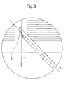
- 1 and 2 are two metal staples applied with the new stapler and lines 3 and 4 are the axis of the stapler, namely the intersection of the plane of the stapler with the plane of the newspaper, while the stapler applies the staples onto the newspaper.
- Line 5 represents both the axis of the two staples and the supposed central spine line of the sheets arranged on top of one another forming the angle ⁇ both with line 3 and line 4.
- the staples of the staplers currently available on the market are laterally glued to the adjacent ones, so as to build a stick of metal staples.
- the new type of stapler uses suitable metal staples that are laterally glued to the adjacent ones, so as to build a new type of staple stick.
- This new type of suitable metal staples is shown in figure 4 , where a metal staple is drawn in front and top views together with the section of legs P1 and P2 and of crown T. Both sections have the shape of a rectangle, whose height has been chosen so as to be equal to one and a half times the base for the reasons that will be explained below.
- figure 5 shows a metal staple of the traditional type substantially having the same dimensions, namely width and height, as the new type, this traditional type being drawn in front and top views, as well, together with sections of the legs and of the crown.
- Both sections though, unlike the sections of the new type of staples, have the shape of a square instead of the shape of a rectangle, with the size of the four sides being equal to the size of the base of the above-mentioned rectangle.
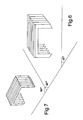
- a portion of a stick of angled metal staples for the new stapler is shown, in a perspective view, in figure 6 and, in order to allow a useful comparison, figure 7 shows, in a perspective view, a portion of a stick of traditional metal staples.
- the first stick portion is drawn in a top view in figure 8 and, similarly, the second stick portion is shown in figure 9 .
- the metal staples of the stick portion of figure 8 and the metal staples of the stick portion of figure 9 have sections of the crown and of legs featuring the same width, as one can assume from figures 4 and 5 , but a different height.
- the staples of the stick portion of figure 6 are glued to one another in a staggered manner, so that the plane on which each staple lies is inclined relative to the longitudinal axis of the stick.
- the section of crown T and of legs P1 and P2 of the staples of the stick portion of figure 6 is a rectangle having a height that is equal to one and a half times the width, as shown in figure 4 .
- the partial gluing between the legs of adjacent staples increases as said angle decreases and as the ratio between the height and the base of the rectangular section of the legs increases.
- a gluing between legs with said ratio equal to two units would be equal to the width of the legs, namely to the base of the rectangle of their section ( figure 13 ).
- the increase of the ratio between the height and the base of the rectangle-shaped section of the legs involves, in the folding of the two legs of the metal staple, a work (force by displacement) increasing with the square of said ratio.
- this metal staple pushed by the relative blade of stapler so as to close in a suitable symmetrical groove, would have the two legs subject not to a simple bending movement, with a consequent correct closing, but to a bending-twisting movement with a consequent defective closing.
- the gluing between adjacent crowns needs to be so effective as to ensure to the stick the stiffness needed by it to be handled, without involving a manual difficulty of the operator when the staples are being applied.
- Another possibility to adopt said type of metal staples consists in applying, during the manufacturing procedure, under and/or on each stick, a suitable adhesive tape that joins the crowns of the staples and is adapted to allow the stick to be handled as well as to be cut by the blade of the stapler, without involving manual difficulties for the operator when the staple is being applied.
- the stapler according to the present invention like the majority of the current staple models, consists of three main mechanical components that are the dispenser, the actuating lever, and the case.
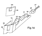
- Dispenser S is shown in figure 14 in a perspective view. It is meant to hold the metal staples glued to one another so as to build the stick of staples shown in figure 6 .
- One or more sticks can be accommodated in a channel S1 having a cross section with the shape of a rectangle and slightly larger than the similar cross section of the sticks, so that they can slide therein pushed by angled pusher S2.
- the angle of the pusher relative to the longitudinal axis of the dispenser is the same angle as the one of the staples of figure 6 , selected, in a non-limiting manner, so as to be equal to forty-five angular degrees.
- the dispenser is provided, at one end, with a seat for pusher blade S5, said seat lying in the same angled plane as the staples of figure 6 relative to the axis of the dispenser. Said blade slides in grooves S3 and S4. Blade S5 pushes the metal staples so as to cause them to perforate the sheets and then close in a suitable symmetrical groove.
- the dispenser at the other end, is provided with a hooking hole S6 for pusher S2, which is actuated by cylindrical spring S7 and always keeps the face of the stick of metal staples pressed against head S8 of the dispenser, both of them being arranged at an angle relative to the longitudinal axis of the dispenser, with a single metal staple precisely arranged under blade S5, which has angled sides and vertically slides in the seat that is laterally delimited by the two angled grooves S3 and S4.
- the dispenser is centrally provided with two holes S10 and S11, through which pin C1 of case C shown in figure 16 extends.
- Actuating lever L is shown in figure 15 in a perspective view. It is centrally provided with two holes L1 and L2, through which pin C1 of cover C shown in figure 16 extends.
- the actuating lever is shown in figure 15 in a perspective view. It is centrally provided with two holes L1 and L2, through which pin C1 of case C shown in figure 16 extends.
- the actuating lever in the lower part L4, is generally shaped as the fingers of the hand of the operator and, above said lower part, it has hook L5, which is connected to a cylindrical pulling spring that is connected to hook C2 of the case of figure 16 .
- Said actuating lever is always kept in an open position by said spring and, when it is activated and, thus, caused to rotate around said pin by means of its end L3 that has a rectangular shape and is inserted in the rectangular hole S12 of the blade, acts upon said blade.
- the actuating lever at first, due to the friction of the blade against its seat, brings head S8 of the dispenser close the sheets held together, thus compressing them, and then pushes the blade so as to cause it to move downwards in its seat in order to push the metal staple arranged underneath and cause it to perforate the sheets and then close in the relative symmetrical groove C5 of the case.
- the case is shown in figure 16 in a perspective view. It contains the front part of the dispenser described above, with all its components, and contains the front part of the actuating lever. It is centrally provided with pin C1, integral thereto, around which both the dispenser and the actuating lever rotate, the latter being always kept open by the relative cylindrical spring, as mentioned above.
- compartment C3 which is adapted to receive the sheets to be stapled and carries, on support C4 for the sheets, symmetrical groove C5, which is adapted to flex the legs of the metal staple so as to cause them to close.
- the angle of said groove C5 relative to the longitudinal axis of the dispenser is substantially the same as the one of the stick of staples of figure 6 , of head S8 of the dispenser, and of the front part of pusher S2.
- a stapler provided with a kinematic mechanism that is one of the simplest mechanisms currently available.
- This kinematic mechanism consists of a few components, among which there are, for example, a single pin a simple pusher.
- the present invention which can also be used to facilitate the reading of newspapers, allows sheets folded as an exercise book and open foolscap sheets to be stapled, but it mainly allows sheets to be joined and stapled by means of a metal staple that is very easily applied on their top left corner and has a direction that makes it easier for readers to consult the sheets without damaging them, contrary to the currently very frequent direction of the diagonal of the sheets between the top left corner and the bottom right corner. Therefore, this invention is very useful in offices, schools, and at home.
Landscapes
- Engineering & Computer Science (AREA)
- Mechanical Engineering (AREA)
- General Engineering & Computer Science (AREA)
- Portable Nailing Machines And Staplers (AREA)
Applications Claiming Priority (1)
| Application Number | Priority Date | Filing Date | Title |
|---|---|---|---|
| IT000438A ITTO20130438A1 (it) | 2013-05-30 | 2013-05-30 | Cucitrice a punti metallici. |
Publications (1)
| Publication Number | Publication Date |
|---|---|
| EP2808128A1 true EP2808128A1 (de) | 2014-12-03 |
Family
ID=48951519
Family Applications (1)
| Application Number | Title | Priority Date | Filing Date |
|---|---|---|---|
| EP14168273.2A Withdrawn EP2808128A1 (de) | 2013-05-30 | 2014-05-14 | Metallklammernklammergerät |
Country Status (4)
| Country | Link |
|---|---|
| US (1) | US20140353354A1 (de) |
| EP (1) | EP2808128A1 (de) |
| CN (1) | CN104400754A (de) |
| IT (1) | ITTO20130438A1 (de) |
Citations (3)
| Publication number | Priority date | Publication date | Assignee | Title |
|---|---|---|---|---|
| US2380786A (en) * | 1944-07-22 | 1945-07-31 | Richard A Percoco | Staple |
| US3119112A (en) * | 1959-12-23 | 1964-01-28 | Wilbur O Thompson | Stapler |
| US4236440A (en) * | 1978-08-31 | 1980-12-02 | Haber Terry M | Truss staple |
Family Cites Families (5)
| Publication number | Priority date | Publication date | Assignee | Title |
|---|---|---|---|---|
| US2619637A (en) * | 1949-08-20 | 1952-12-02 | Arrow Fastener Co Inc | Plier type stapler |
| IT1216631B (it) * | 1988-04-22 | 1990-03-08 | Balma Capoduri E C S P A | Cucitrice a punti metallici, adispezionabilita' facilitata. |
| US5364000A (en) * | 1993-04-14 | 1994-11-15 | Stanley-Bostitch, Inc. | Stapling plier |
| US6726081B1 (en) * | 2003-02-19 | 2004-04-27 | Jui-Yuan Lin | Stapling apparatus with a safety device for staplers to prevent staples from popping out of a stapler |
| US8281971B2 (en) * | 2010-09-15 | 2012-10-09 | Apex Mfg. Co., Ltd. | Labor-saving stapler |
-
2013
- 2013-05-30 IT IT000438A patent/ITTO20130438A1/it unknown
-
2014
- 2014-05-14 EP EP14168273.2A patent/EP2808128A1/de not_active Withdrawn
- 2014-05-30 US US14/292,038 patent/US20140353354A1/en not_active Abandoned
- 2014-05-30 CN CN201410539318.7A patent/CN104400754A/zh active Pending
Patent Citations (3)
| Publication number | Priority date | Publication date | Assignee | Title |
|---|---|---|---|---|
| US2380786A (en) * | 1944-07-22 | 1945-07-31 | Richard A Percoco | Staple |
| US3119112A (en) * | 1959-12-23 | 1964-01-28 | Wilbur O Thompson | Stapler |
| US4236440A (en) * | 1978-08-31 | 1980-12-02 | Haber Terry M | Truss staple |
Also Published As
| Publication number | Publication date |
|---|---|
| US20140353354A1 (en) | 2014-12-04 |
| CN104400754A (zh) | 2015-03-11 |
| ITTO20130438A1 (it) | 2014-12-01 |
Similar Documents
| Publication | Publication Date | Title |
|---|---|---|
| WO2003095152A1 (en) | Cartridge for stapler and stapler | |
| EP2495107A1 (de) | Papierbindungswerkzeug | |
| CN104260058A (zh) | 一种有装订标尺的订书机 | |
| JP4659364B2 (ja) | 製本システム | |
| US20140353354A1 (en) | Metal staples stapler | |
| CN103434293B (zh) | 一种多功能装订机 | |
| JP6146189B2 (ja) | 中綴じ機 | |
| CN103894977B (zh) | 多功能订书机 | |
| KR102204914B1 (ko) | 클립끼움형 바인더 | |
| CN207058492U (zh) | 一种整齐装订订书机 | |
| JP6605314B2 (ja) | 中綴じ製本装置 | |
| CN104405748B (zh) | 订书钉 | |
| JP3174029U (ja) | 目盛り付きホッチキス | |
| CN104968506A (zh) | 文件装订夹、印刷物套件、印刷物和印刷物的制造方法 | |
| JP2013056410A (ja) | 書類綴じ補助器 | |
| JP2020055277A (ja) | 針無し紙綴じ器 | |
| CN104400756A (zh) | 订书机 | |
| DE102009052854A1 (de) | Hefteinband mit Abheftvorrichtung zur Aufnahme gelochter Blätter | |
| JPH0540941Y2 (de) | ||
| JP2005193316A (ja) | ステープラ | |
| JPH0544153Y2 (de) | ||
| JP3222484U (ja) | 紙製綴じ具を用いた冊子 | |
| US2335057A (en) | Binding device | |
| JP2019064244A (ja) | 紙綴じ用カッター | |
| JP3167086U (ja) | 加増可能なファイル |
Legal Events
| Date | Code | Title | Description |
|---|---|---|---|
| PUAI | Public reference made under article 153(3) epc to a published international application that has entered the european phase |
Free format text: ORIGINAL CODE: 0009012 |
|
| 17P | Request for examination filed |
Effective date: 20140514 |
|
| AK | Designated contracting states |
Kind code of ref document: A1 Designated state(s): AL AT BE BG CH CY CZ DE DK EE ES FI FR GB GR HR HU IE IS IT LI LT LU LV MC MK MT NL NO PL PT RO RS SE SI SK SM TR |
|
| AX | Request for extension of the european patent |
Extension state: BA ME |
|
| R17P | Request for examination filed (corrected) |
Effective date: 20150528 |
|
| RBV | Designated contracting states (corrected) |
Designated state(s): AL AT BE BG CH CY CZ DE DK EE ES FI FR GB GR HR HU IE IS IT LI LT LU LV MC MK MT NL NO PL PT RO RS SE SI SK SM TR |
|
| STAA | Information on the status of an ep patent application or granted ep patent |
Free format text: STATUS: REQUEST FOR EXAMINATION WAS MADE |
|
| STAA | Information on the status of an ep patent application or granted ep patent |
Free format text: STATUS: THE APPLICATION IS DEEMED TO BE WITHDRAWN |
|
| 18D | Application deemed to be withdrawn |
Effective date: 20161201 |