EP2808001B1 - Sitz-Vorrichtung mit Aufstehhilfe - Google Patents
Sitz-Vorrichtung mit Aufstehhilfe Download PDFInfo
- Publication number
- EP2808001B1 EP2808001B1 EP13005462.0A EP13005462A EP2808001B1 EP 2808001 B1 EP2808001 B1 EP 2808001B1 EP 13005462 A EP13005462 A EP 13005462A EP 2808001 B1 EP2808001 B1 EP 2808001B1
- Authority
- EP
- European Patent Office
- Prior art keywords
- armrest
- seat
- seating device
- holder
- seating
- Prior art date
- Legal status (The legal status is an assumption and is not a legal conclusion. Google has not performed a legal analysis and makes no representation as to the accuracy of the status listed.)
- Active
Links
- 0 CC1=C(C)C2=*CC1C2 Chemical compound CC1=C(C)C2=*CC1C2 0.000 description 1
Images





Classifications
-
- A—HUMAN NECESSITIES
- A61—MEDICAL OR VETERINARY SCIENCE; HYGIENE
- A61G—TRANSPORT, PERSONAL CONVEYANCES, OR ACCOMMODATION SPECIALLY ADAPTED FOR PATIENTS OR DISABLED PERSONS; OPERATING TABLES OR CHAIRS; CHAIRS FOR DENTISTRY; FUNERAL DEVICES
- A61G5/00—Chairs or personal conveyances specially adapted for patients or disabled persons, e.g. wheelchairs
- A61G5/10—Parts, details or accessories
- A61G5/14—Standing-up or sitting-down aids
Definitions
- the invention relates to a seating device including holder, a seat borne by the holder and at least one armrest, wherein the seat is transferable between a normal position of use and a forwardly tilted rising position.
- the invention particularly relates to a chair having such a seat.
- WO 85/00006 shows a chair wherein the armrest is hinged at the rear to the backrest and is hinged at the front to a first rod of a pair of rods, the second rod of which is hinged to the frame of the chair and with one end is connected to the seat so as to slide.
- the seat is furthermore hinged to another rod, which at the rear is connected to the frame and forms a kind of scissors with the said second rod.
- WO 2011/141617 shows a chair having an operable seat, wherein by pressing the armrest downwards a four-rod mechanism forming the connection between seat and frame is operated in order to lift the seat and tilt it forward to some extent.
- the invention provides a seating device according to claim 1.
- the armrest can be placed in a higher position for starting the operation, the user's hands can remain at a higher level during the process of pressing down the armrests, thus enhancing the user's stability while rising.
- the armrest will usually extend substantially horizontally.
- the holder in case of a chair will be a chair frame.
- the holder is composed, for instance a wall to which the arm rest is attached and a floor on which the seat is supported. Toilet arrangements and shower seating arrangements can also be considered.
- the armrests can in that case also be attached to a support for seat, which support is attached to the floor, such as a toilet bowl.
- the armrest can be pressed downwards into an end operation position corresponding with the position of use.
- the user's hands are thus in a stable end position, corresponding with that of a normal seating device, in particular a chair, and not (much) lower as is the case in the said known chairs.
- the armrest is hinged to the holder. In the starting position the armrest can extend upwardly inclined from the hinge.
- the armrest is attached to the holder near its rear end, as a result of which at the location where the user engages the armrest, in many cases at the front, the stroke can be large.
- the seat is hinged to the holder near its front edge.
- both armrests can be connected to each other to form an armrest set that can be moved as one unity, as a result of which the user's stability when rising can be enhanced.
- both armrests are each individually hinged to the holder.
- the operation mechanism is disposed on one side only, preferably however on both sides, in which case both armrests are part of operation mechanisms.
- the seating device can be provided with a locking device for locking the armrest in the position of use and with operation means for unlocking the locking device.
- the operation means may then comprise an operation member in the front end of the armrest. Thus inadvertent activation of the operation mechanism is prevented. The armrest cannot be lifted then.
- the operation mechanism comprises an operation rod, which with its upper end is rotatably connected to the armrest and with its lower end is rotatably connected to a further part of the operation mechanism.
- the further part of the operation mechanism can be accommodated in a chamber provided in the holder, adjacent the seat, thus reducing the risk of injury.
- the upper end of the operation rod can be transferable along the armrest between a passive position and an active position, wherein in the active position of the upper end of the operation rod, the operation rod takes up an active orientation with an angle relative to the vertical that is larger than in the passive orientation of the operation rod in which the upper end is in the passive position.
- the operation rod is placed in an orientation that is advantageous for transmission of forces during rising.
- the rearwardly opening angle between the operation rod and the armrest preferably always exceeds 90 degrees. In the position of use, wherein the forces on the armrest are small, the operation rod can form a support for the armrest.
- the active position of the upper end of the operation rod is situated closer to the front end of the armrest than the passive position thereof.
- Said locking device can be active in locking the upper end of the operation rod in the passive position, in order to prevent inadvertent operation.
- the seating device can be provided with a retaining member for keeping the upper end of the operation rod in the active position, wherein the upper end preferably comprises a retaining pin that can be moved in and out of the retaining member.
- the seating device can be provided with release means for urging the upper end of the operation rod out of the retaining member, so that the upper end is able to move back again to the passive position for normal use or for a next rising action.
- the release means comprise a release member that is prebiassed at accommodation of the upper end/retaining pin of the operation rod in the retaining member for generating a force urging said upper end, in particular the retaining pin, out of the retaining member. In that way it can be achieved that immediately following a rising action the operation mechanism is able to return to a passive orientation again.
- the release means are operable by means of an auxiliary operation mechanism, which auxiliary operation mechanism comprises the armrest.
- the auxiliary operation mechanism may in a further compact embodiment comprise an auxiliary operation rod movable along, in particular in, the armrest.
- the release means are operable by the auxiliary operation mechanism for after reaching the position of use of the armrest urging the upper end of the operation rod out of the retaining member. In that way it can be achieved that immediately following a rising action the operation mechanism is able to return to a passive orientation again.
- the other end, the lower end, of the operation rod can be rotatably connected to the one leg of a rocker lever, having two legs and in between is rotatably attached to the holder, and with the other leg is movably connected to the seat.
- the downward motion of the armrest and thus the operation rod is converted by the rocker lever into an upward tilting motion of the seat.
- the rocker lever with its other leg through intermediary of a sliding joint, can be connected to the seat so as to slide, wherein the sliding joint is attached to the seat by means of a hinge joint.
- a shock absorber which can be part of the sliding joint, can be placed between the other leg and the seat.
- the holder will be formed by a chair frame, wherein the chair frame furthermore comprises a back part, wherein the armrests are hinged to the back part.
- the back part can be formed by upright frame parts, in between which for instance a cloth is stretched, or by a rigid backrest also functioning as a frame.
- the armrests can be connected to each other by a transverse member situated behind the back part, which transverse member preferably is at least locally spaced apart from the back part. In that way a grip is provided for moving the chair.
- the back part can furthermore be provided with a stop for the armrest against its downward movement relative to the normal position of use.
- the invention provides a chair comprising a frame, a seat and at least one armrest, wherein near its front side the seat is hinged to the frame, for transfer between a substantially horizontal seating position and a forwardly tilted rising position, furthermore comprising an operation mechanism for the transfer of the seat from the seating position to the rising position, wherein the armrest is part of the operation mechanism and for that purpose is attached to the frame so as to move, in particular so as to hinge, in particular so as to move in a vertical plane, for transferring it downwards between a starting position and a lower end operation position while urging the seat into the rising position.
- the starting position can be situated higher than the normal position of use and the end operation position can correspond with the normal position of use.
- the operation mechanism can be built in accordance with the embodiments thereof described above.
- the invention provides a seating device comprising a holder, a seat and at least one armrest, wherein near the front side the seat is hinged to the holder for transfer between a substantially horizontal seating position and a forwardly tilted rising position, further comprising an operation mechanism for the transfer of the seat from the seating position to the rising position, wherein the armrest is part of the operation mechanism and for that purpose above the rear side of the seat is attached to the holder so as to move, in particular so as to hinge, in particular so as to move in a vertical plane, for by exerting pressure thereon transferring it downwards between a starting position and a lower end operation position while urging the seat into the rising position.
- the starting position can be situated higher than the normal position of use and the end operation position can correspond with the normal position of use.
- the operation mechanism can be built in accordance with the embodiments thereof described above.
- the seating device according to the invention designed like a chair, can be designed lightweight and can be compact. Contrary to motor-driven rising chairs, the invention is particularly suitable for use in dining room chairs, waiting room chairs and meeting room chairs.
- US 3.259.427 shows a chair without armrests, the seat of which is provided with projecting rods at the front side, which rods form levers for allowing the seat to tilt upwards, in one embodiment by exerting downward pressure on the levers, in another embodiment by exerting an upward pull on the levers.
- a chair having a seat that can be adjusted relative to the frame, wherein the seat can be tilted rearward by means of a gas jack that is activated by means of a lever that is hinged to the armrest.
- FR 2.639.807 shows a chair having armrests that are able to tilt forward over a small distance about a hinge situated below the seat, for releasing a gas jack for tilting the seat forward.
- US 2010/0141003 describes a chair having an armrest that can be vertically pushed down with which a cable-pulley system is operated for tilting the seat forward.
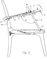
- the chair 80 of figure 1 comprises a frame 81 having legs 82, a backrest 18, a seat 21 and armrests 1.
- the seat 21 is attached to the frame 81 by means of hinges 14 for a swinging motion in directions F and with its rear edge it freely supports on a stop 19 that is fixed to the frame 81.
- the armrests 1 are attached by hinges 10 to the backrest 18 (or a part of the frame 81 if it is situated there to support a backrest attached thereto) and they can be swung in directions A. Behind hinges 10 and behind backrest 19 the armrests 1 can be connected to each other by a transverse member 1a, so that they form one U-shaped unity. Alternatively they can be attached by means of a hinge to an armrest end portion, that is stationarily attached to the backrest. Behind the backrest 18, the transverse member 1a may form a free grip for a hand. At locations further to the fore the armrests 1 are supported by a link rod or operation rod 8, yet to be discussed. In the operation position shown, the armrests 1 near the backrest 18 rest on fixed stops or support surfaces 20. The rearwardly opening angle ⁇ between each rod 8 and armrest 1 is obtuse.
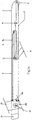
- each of the armrests 1 a slot 6 is accommodated in which slot a pin-shaped upper end 5 of the rod 8 is accommodated so as to slide in directions C1,2.
- the slot 6 is provided with an upwardly turned retaining end 7, in which the pin 5 can be retained.
- both (preferably hollow) armrests 1 is furthermore accommodated (preferably in a chamber formed in the armrest) a release mechanism for urging the said pin 5 out of the retaining end 7.
- Said release mechanism comprises an unblocking pull rod 9, which at the one end is provided with a spring lip 9a and at the other end with a drive plate 9b which at the location of 9d is hinged (directions B) to the armrest 1 and on which a pin 9e is attached extending in stationary slot 9f in backrest 18 and can be slid in there in directions K.
- each armrest 1 thus has a facility to extend the stroke length of the respective unblocking pull rod 9 with springy element 9a.
- the rod 9 can be transferred within the said armrest 1 in the directions G.
- each armrest 1 is furthermore accommodated a locking/unlocking rod 3, which is tiltable about hinge 4 in directions H1,2 and at the one end, the front end, is provided with an operation knob 2 and at the opposite rear end is provided with a stop 3a for in the locking position securing the pin 5 in the rear end of the slot 6, the passive position.
- a locking/unlocking rod 3 which is tiltable about hinge 4 in directions H1,2 and at the one end, the front end, is provided with an operation knob 2 and at the opposite rear end is provided with a stop 3a for in the locking position securing the pin 5 in the rear end of the slot 6, the passive position.
- the rod 8 With its lower end the rod 8 is rotatably attached by hinge 8a to the front arm 11a of a rocker lever 11, which at the location of 12 is attached to the frame 81 so as to hinge in directions E.
- the right arm 11b of the rocker lever 11 is provided with a pin 13, which is slidable in directions J in a slot 15 provided on the seat 21.
- the pin 13 is furthermore rotatably attached to the end of a shock absorber 16, which at the other end is attached to the seat 21 by a stationary hinge 17.
- the hinge 8a, the rocker lever 11 and the shock absorber 16 can be accommodated in a chamber (not shown) in the frame 81.
- both seat 21 and armrests 1 are blocked because the locking 3a in question blocks pin 5 in slot 6 of the rod 8.
- the armrests 1 cannot be moved downwards because of stopping against stops or support surfaces 20.
- the seat 21 cannot be moved upwards because the rods 8 stop the rocker levers 11 from rocking so that the arms 11 b and thus the pins 13 retain their positions.
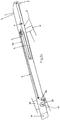
- each drive plate 9b will furthermore move the respective unblocking pull rod 9 with springy element 9a forward (G1, figure 2C ) by rotating (B1) the drive plate 9b about hinge point 9d on armrest 1, urged by fixed pin 9e which will follow the slot 9f in the backrest 18.
- the springy element 9a on unblocking pull rod 9 will now release the retaining end 7 in armrest 1, so that the pin 5 is able to get in front of or in the retaining end 7.
- the pins 13 remain in their places in the rear end of the slots 15 and the seat 21 remains supported on stop 19.
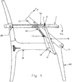
- each pin 5 reliably, direction C3, arrives in its active position in retaining end 7 and due to downward rotation (A2) of the armrests (which as a result of the transverse member 1a move as one unity and therefore synchronously) on both sides, via operation rod 8, the rocker lever 11 in question will be rotated about hinge point 12, direction E1.
- the forwardly tilted, more vertical orientation of the rods 8 here enhances the transmission of forces. Due to the tilting of the rocker lever 11 the seat 21, and with it (via shock absorber 16) pin 13, will be moved upwards from the seating position of figure 1 , tilt, about hinge point 14, direction F1.
- pin 13 is able to move forwards (J1) in slot 15 the connection between hinges 12 and 17 may increase in length in order to permit a rotation of the seat 21 about hinge 14. Due to the forward motion of pin 13 in slot 15, pin 13, pulls out the shock absorber 16 that is also attached to seat 21 via attachment point 17.
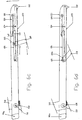
- each armrest 1 contacts blocking surface 20 because of the downward force, see figures 4 and 4A , the unblocking pull rod 9 with springy element 9a is pulled into blocking recess 7 above blocking cam 5 of pressure rod 8 via drive plate 9b. At reduction or ending the downward force on armrests 1 exerted by the user, each springy element 9a will push (C4) blocking cam 5 of pressure 8 out of the blocking recess 7.
- both armrests 1 support on stops or support surfaces 20, in an orientation corresponding with that of the position of use.
- the path of pressing the armrests 1 down is in this case above the position of use of the armrests, so that the user when rising does not need to go down with his/her arms too much, as is the case in the known chairs, which would be disadvantageous for the transmission of forces and the user's posture.
- the pin 5 of pressure rod 8 is now able to move freely rearward in slot 6 of armrest 1, direction C2, see figure 5 and 5A , which is induced by the seat 2 tilting back as a result of gravity and urges the stop 3a out of the way (H1) which after the pin 5 has arrived at the end of the slot 6 snaps back again, H2.
- the pin 13 is moved back in slot 15 (J2) so that the shock absorber 16 becomes active and the seat 21 is able to hinge back about hinge point 14 in a cushioned manner to the initial position or resting orientation of figure 1 .
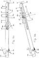
- Figures 6A-D show another, simple release mechanism in an armrest 101, preferably in both armrests, of a seating device, in this case chair, according to the invention.
- Said release mechanism comprises an elongated leaf spring 109 having a free end 109a and an end 109b that in a clamped manner is attached in the armrest 101.
- the leaf spring 109 is elastically deformable in the plane of the drawing, wherein figure 6A shows the relaxed position.
- the pin 105 can be slid in the directions C1,2 within the slot 106 in the armrest 101.
- the end of the slot 106 that is distal relative to the backrest 118 is provided with a retaining end 107 having an inclined run-in edge 107a and an upright stop edge 107b for stopping the pin 105 in proximal direction.
Landscapes
- Health & Medical Sciences (AREA)
- Life Sciences & Earth Sciences (AREA)
- Animal Behavior & Ethology (AREA)
- General Health & Medical Sciences (AREA)
- Public Health (AREA)
- Veterinary Medicine (AREA)
- Seats For Vehicles (AREA)
- Chair Legs, Seat Parts, And Backrests (AREA)
Claims (17)
- Sitzvorrichtung (80), umfassend eine Halterung (81), einen Sitz (21) und mindestens eine Armlehne (1), wobei der Sitz zum Übergang zwischen einer im Wesentlichen horizontalen Sitzposition und einer nach vorne geneigten Aufwärtsposition beweglich an der Halterung befestigt ist, ferner umfassend einen Betätigungsmechanismus (1, 5, 6, 8, 8a, 11, 12) für den Übergang des Sitzes von der Sitzposition in die Aufwärtsposition, wobei die Armlehne (1) Teil des Betätigungsmechanismus ist, dadurch gekennzeichnet, dass die Armlehne (1), um Teil des Betätigungsmechanismus zu sein, an der Halterung (81) befestigt ist, um sich in einer vertikalen Ebene zu bewegen, zum Übergang zwischen einer normalen Gebrauchsposition und einer höher gelegenen Ausgangsposition, um den Betrieb des Übergangs des Sitzes von der Sitzposition in die Aufwärtsposition zu beginnen, und von dieser Ausgangsposition aus nach unten in eine Betriebsposition gedrückt werden kann, die niedriger als die Ausgangsposition liegt, während der Sitz (21) in die Aufwärtsposition gebracht wird.
- Sitzvorrichtung nach Anspruch 1, wobei die Armlehne (1) nach unten in eine Endbetriebsposition gedrückt werden kann, die der Gebrauchsposition entspricht.
- Sitzvorrichtung (80) nach Anspruch 1 oder 2, umfassend zwei derartige Armlehnen (1), wobei die beiden Armlehnen miteinander verbunden sind, um einen Armlehnensatz zu bilden, der als eine Einheit bewegt werden kann.
- Sitzvorrichtung (8) nach einem der vorhergehenden Ansprüche, versehen mit einer Verriegelungsvorrichtung (3, 3a, 4) zum Verriegeln der Armlehne (1) in der Gebrauchsposition und mit Betätigungsmitteln (2) zum Entriegeln der Verriegelungsvorrichtung, wobei die Betätigungsmittel ein Betätigungselement (2) am vorderen Ende der Armlehne (1) umfassen.
- Sitzvorrichtung nach einem der vorhergehenden Ansprüche, wobei der Betätigungsmechanismus (1, 5, 6, 8, 8a, 11, 12) eine Betätigungsstange (8) umfasst, die mit ihrem oberen Ende drehbar mit der Armlehne (1) und mit ihrem unteren Ende (8a) drehbar mit einem weiteren Teil (11) des Betätigungsmechanismus verbunden ist, wobei vorzugsweise der weitere Teil (11) des Betätigungsmechanismus in der normalen Gebrauchsposition der Sitzvorrichtung in einer in der Halterung (81) vorgesehenen Kammer neben dem Sitz (21) untergebracht ist.
- Sitzvorrichtung nach Anspruch 5, wobei das obere Ende der Betätigungsstange (8) auch entlang der Armlehne (1) zwischen einer passiven Position und einer aktiven Position übertragbar ist, wobei die Betätigungsstange in der aktiven Position des oberen Endes der Betätigungsstange eine aktive Ausrichtung mit einem Winkel relativ zur Vertikalen annimmt, der größer ist als in der passiven Ausrichtung der Betätigungsstange, in der sich das obere Ende in der passiven Position befindet, wobei vorzugsweise die aktive Position des oberen Endes näher am vorderen Ende der Armlehne angeordnet ist als die passive Position derselben, wobei vorzugsweise der rückwärtige Öffnungswinkel zwischen der Betätigungsstange und der Armlehne immer mehr als 90 Grad beträgt.
- Sitzvorrichtung nach Anspruch 4 und Anspruch 6, wobei die Verriegelungsvorrichtung (3, 3a, 4) aktiv ist, um das obere Ende der Betätigungsstange in der passiven Position zu verriegeln.
- Sitzvorrichtung nach Anspruch 6 oder 7, versehen mit einem Halteelement (7) zum Halten des oberen Endes der Betätigungsstange (8) in der aktiven Position, wobei das obere Ende vorzugsweise einen Haltestift (5) umfasst, der in das und aus dem Halteelement (7) bewegt werden kann.
- Sitzvorrichtung nach einem der Ansprüche 5-8, wobei das untere Ende (8a) der Betätigungsstange (8) drehbar mit dem einen Schenkel (11a) eines Kipphebels (11) verbunden ist, der drehbar an der Halterung (81) und mit dem anderen Schenkel (11b) beweglich mit dem Sitz verbunden ist, wobei vorzugsweise der Kipphebel mit dem anderen Schenkel (11b) durch Zwischenschaltung eines Gleitgelenks (13, 15) mit dem Sitz (21) gleitend verbunden ist, wobei das Gleitgelenk über ein Scharniergelenk (17) am Sitz befestigt ist, wobei vorzugsweise zwischen dem anderen Schenkel (11b) und dem Sitz (21) ein Stoßdämpfer (16) angeordnet ist, der insbesondere Teil des Gleitgelenks ist.
- Sitzvorrichtung nach einem der vorhergehenden Ansprüche, wobei die Halterung (81) durch einen Stuhlrahmen gebildet ist, wobei der Stuhlrahmen ferner ein Rückenteil (18) umfasst, wobei die Sitzvorrichtung zwei Armlehnen (1) aufweist, wobei die Armlehnen (1) an dem Rückenteil gelenkig gelagert sind.
- Sitzvorrichtung nach Anspruch 10, wenn abhängig von Anspruch 3, wobei die Armlehnen (1) durch ein hinter dem Rückenteil (18) angeordnetes Querelement (1a) miteinander verbunden sind, das vorzugsweise zumindest lokal vom Rückenteil beabstandet ist.
- Sitzvorrichtung nach einem der vorhergehenden Ansprüche, wobei die Halterung (81), insbesondere, wenn vorhanden, ein Stuhlrückenteil (18) mit einem Anschlag (20) für die Armlehne gegen deren Abwärtsbewegung gegenüber der normalen Gebrauchsposition versehen ist.
- Sitzvorrichtung nach einem der vorhergehenden Ansprüche, die als Esszimmerstuhl oder als Besprechungszimmerstuhl ausgeführt ist.
- Sitzvorrichtung nach einem der vorhergehenden Ansprüche, wobei der Sitz (21) nahe seiner Vorderkante an der Halterung gelenkig gelagert (14) ist.
- Sitzvorrichtung nach einem der vorhergehenden Ansprüche, wobei die Armlehne (21) an der Halterung nahe dem hinteren Ende der Armlehne befestigt ist.
- Sitzvorrichtung nach einem der vorhergehenden Ansprüche, wobei die Armlehne (1) an der Halterung gelenkig gelagert ist, so dass sich die Armlehne in der Ausgangsposition vom Scharnier (10) nach oben geneigt erstreckt.
- Sitzvorrichtung nach einem der vorhergehenden Ansprüche, wobei die normale Gebrauchsposition der Armlehne (1) eine im Wesentlichen horizontale Gebrauchsposition ist.
Applications Claiming Priority (1)
| Application Number | Priority Date | Filing Date | Title |
|---|---|---|---|
| NL1039910A NL1039910C2 (nl) | 2012-11-23 | 2012-11-23 | Opstahulp. |
Related Child Applications (1)
| Application Number | Title | Priority Date | Filing Date |
|---|---|---|---|
| EP19175439.9 Division-Into | 2019-05-20 |
Publications (2)
| Publication Number | Publication Date |
|---|---|
| EP2808001A1 EP2808001A1 (de) | 2014-12-03 |
| EP2808001B1 true EP2808001B1 (de) | 2020-04-29 |
Family
ID=47790424
Family Applications (1)
| Application Number | Title | Priority Date | Filing Date |
|---|---|---|---|
| EP13005462.0A Active EP2808001B1 (de) | 2012-11-23 | 2013-11-21 | Sitz-Vorrichtung mit Aufstehhilfe |
Country Status (4)
| Country | Link |
|---|---|
| EP (1) | EP2808001B1 (de) |
| DK (1) | DK2808001T3 (de) |
| ES (1) | ES2807892T3 (de) |
| NL (1) | NL1039910C2 (de) |
Families Citing this family (4)
| Publication number | Priority date | Publication date | Assignee | Title |
|---|---|---|---|---|
| EP3310314B1 (de) | 2015-06-19 | 2022-10-26 | Senior Life LLC | Hebehilfestuhl |
| DE102017114813B4 (de) * | 2017-07-03 | 2019-02-07 | René Heller | Aufsetzbarer toilettensitz |
| NL2026723B1 (nl) | 2020-10-21 | 2022-06-28 | Anthonius Johannes Tolboom | Zitinrichting |
| EP4346531A4 (de) | 2021-06-03 | 2025-05-14 | Home Furnishings Resource Group Inc. D/B/A F3 | Hilfsvorrichtung zum heben eines badezimmers |
Family Cites Families (9)
| Publication number | Priority date | Publication date | Assignee | Title |
|---|---|---|---|---|
| US170293A (en) * | 1875-11-23 | Improvement in reclining rocking-chairs | ||
| US3259427A (en) * | 1965-10-18 | 1966-07-05 | Ray S Wiest | Leverage seat lifts |
| GB8316651D0 (en) * | 1983-06-18 | 1983-07-20 | Boardman P A | Tilting armchair |
| FR2639807A1 (fr) * | 1988-12-01 | 1990-06-08 | Jouk Leon | Siege a assise pivotante |
| FR2856282B1 (fr) * | 2003-06-19 | 2006-02-17 | Lifestand Internat Sa | Siege verticalisateur a modification automatique de l'inclinaison du dossier |
| FR2856486B1 (fr) | 2003-06-19 | 2005-11-04 | Lifestand Internat Sa | Poignee multiprises et fauteuil verticalisateur en faisant application |
| GB2460685B (en) * | 2008-06-05 | 2013-01-30 | Susan Walsh | An inclusive chair |
| US7735926B1 (en) * | 2008-12-09 | 2010-06-15 | Combs John A | Chair lift |
| FI20105532A0 (fi) | 2010-05-14 | 2010-05-14 | Jorma Eerola | Istuinjärjestely |
-
2012
- 2012-11-23 NL NL1039910A patent/NL1039910C2/nl active
-
2013
- 2013-11-21 ES ES13005462T patent/ES2807892T3/es active Active
- 2013-11-21 DK DK13005462.0T patent/DK2808001T3/da active
- 2013-11-21 EP EP13005462.0A patent/EP2808001B1/de active Active
Non-Patent Citations (1)
| Title |
|---|
| None * |
Also Published As
| Publication number | Publication date |
|---|---|
| NL1039910C2 (nl) | 2014-05-27 |
| DK2808001T3 (da) | 2020-07-20 |
| ES2807892T3 (es) | 2021-02-24 |
| EP2808001A1 (de) | 2014-12-03 |
Similar Documents
| Publication | Publication Date | Title |
|---|---|---|
| EP2028973B1 (de) | Verbindungsmechanismus für einen lehnstuhl | |
| EP2549905B1 (de) | Neigungsvorrichtung mit vollständiger flacher streckung | |
| US7475944B2 (en) | Reclining and convertible seating furniture with trendelenburg feature | |
| JP5468791B2 (ja) | 幼児椅子のためのトレイラッチ機構 | |
| US7497512B2 (en) | Recliner drive mechanism for a rocker chair | |
| EP3275340A2 (de) | Gleiterneigungsvorrichtung mit doppelten blockierernocken | |
| EP2808001B1 (de) | Sitz-Vorrichtung mit Aufstehhilfe | |
| US5374101A (en) | Three-way reclining chair | |
| CN101835407A (zh) | 可调节扶手及其使用方法 | |
| GB2583800A (en) | Adjustable backrest and wheelchair therewith | |
| JP2005237944A (ja) | 調節式肘掛、腰掛ユニット | |
| US20070273191A1 (en) | Angle-adjustable backrest device for a child highchair | |
| US7100988B1 (en) | Child's highchair with a reclining back | |
| US20050062322A1 (en) | Rocking chair with automatic locking mechanism | |
| KR200448295Y1 (ko) | 등받이가 전·후 이동되어 바른자세를 유지할 수 있는기능성 의자 | |
| CN120304666A (zh) | 坐具、尤其是儿童高脚椅 | |
| US20090091173A1 (en) | Chair | |
| US4826243A (en) | Recliner chairs | |
| US9301611B2 (en) | Leg and foot support structure to be applied to tiltable armchairs | |
| EP0151141B1 (de) | Kippmechanismus für einen sitz | |
| JP3100800U (ja) | 事務用椅子 | |
| JP2018023569A (ja) | 椅子 | |
| CA2855283C (en) | Mobile chair, method of operation associated thereto, and kit for assembling the same | |
| JP7847372B2 (ja) | 車いす | |
| JP3118362U (ja) | 椅子の調整式背もたれの連動調整構造 |
Legal Events
| Date | Code | Title | Description |
|---|---|---|---|
| PUAI | Public reference made under article 153(3) epc to a published international application that has entered the european phase |
Free format text: ORIGINAL CODE: 0009012 |
|
| 17P | Request for examination filed |
Effective date: 20131121 |
|
| AK | Designated contracting states |
Kind code of ref document: A1 Designated state(s): AL AT BE BG CH CY CZ DE DK EE ES FI FR GB GR HR HU IE IS IT LI LT LU LV MC MK MT NL NO PL PT RO RS SE SI SK SM TR |
|
| AX | Request for extension of the european patent |
Extension state: BA ME |
|
| R17P | Request for examination filed (corrected) |
Effective date: 20150526 |
|
| RBV | Designated contracting states (corrected) |
Designated state(s): AL AT BE BG CH CY CZ DE DK EE ES FI FR GB GR HR HU IE IS IT LI LT LU LV MC MK MT NL NO PL PT RO RS SE SI SK SM TR |
|
| 17Q | First examination report despatched |
Effective date: 20151218 |
|
| GRAP | Despatch of communication of intention to grant a patent |
Free format text: ORIGINAL CODE: EPIDOSNIGR1 |
|
| STAA | Information on the status of an ep patent application or granted ep patent |
Free format text: STATUS: GRANT OF PATENT IS INTENDED |
|
| INTG | Intention to grant announced |
Effective date: 20190802 |
|
| GRAS | Grant fee paid |
Free format text: ORIGINAL CODE: EPIDOSNIGR3 |
|
| GRAJ | Information related to disapproval of communication of intention to grant by the applicant or resumption of examination proceedings by the epo deleted |
Free format text: ORIGINAL CODE: EPIDOSDIGR1 |
|
| GRAL | Information related to payment of fee for publishing/printing deleted |
Free format text: ORIGINAL CODE: EPIDOSDIGR3 |
|
| STAA | Information on the status of an ep patent application or granted ep patent |
Free format text: STATUS: EXAMINATION IS IN PROGRESS |
|
| GRAP | Despatch of communication of intention to grant a patent |
Free format text: ORIGINAL CODE: EPIDOSNIGR1 |
|
| STAA | Information on the status of an ep patent application or granted ep patent |
Free format text: STATUS: GRANT OF PATENT IS INTENDED |
|
| INTC | Intention to grant announced (deleted) | ||
| INTG | Intention to grant announced |
Effective date: 20191129 |
|
| GRAA | (expected) grant |
Free format text: ORIGINAL CODE: 0009210 |
|
| STAA | Information on the status of an ep patent application or granted ep patent |
Free format text: STATUS: THE PATENT HAS BEEN GRANTED |
|
| AK | Designated contracting states |
Kind code of ref document: B1 Designated state(s): AL AT BE BG CH CY CZ DE DK EE ES FI FR GB GR HR HU IE IS IT LI LT LU LV MC MK MT NL NO PL PT RO RS SE SI SK SM TR |
|
| REG | Reference to a national code |
Ref country code: GB Ref legal event code: FG4D |
|
| REG | Reference to a national code |
Ref country code: CH Ref legal event code: EP |
|
| REG | Reference to a national code |
Ref country code: AT Ref legal event code: REF Ref document number: 1262232 Country of ref document: AT Kind code of ref document: T Effective date: 20200515 |
|
| REG | Reference to a national code |
Ref country code: DE Ref legal event code: R096 Ref document number: 602013068338 Country of ref document: DE |
|
| REG | Reference to a national code |
Ref country code: IE Ref legal event code: FG4D |
|
| REG | Reference to a national code |
Ref country code: NL Ref legal event code: FP |
|
| REG | Reference to a national code |
Ref country code: FI Ref legal event code: FGE |
|
| REG | Reference to a national code |
Ref country code: DK Ref legal event code: T3 Effective date: 20200716 |
|
| REG | Reference to a national code |
Ref country code: SE Ref legal event code: TRGR |
|
| REG | Reference to a national code |
Ref country code: NO Ref legal event code: T2 Effective date: 20200429 |
|
| REG | Reference to a national code |
Ref country code: LT Ref legal event code: MG4D |
|
| PG25 | Lapsed in a contracting state [announced via postgrant information from national office to epo] |
Ref country code: GR Free format text: LAPSE BECAUSE OF FAILURE TO SUBMIT A TRANSLATION OF THE DESCRIPTION OR TO PAY THE FEE WITHIN THE PRESCRIBED TIME-LIMIT Effective date: 20200730 Ref country code: LT Free format text: LAPSE BECAUSE OF FAILURE TO SUBMIT A TRANSLATION OF THE DESCRIPTION OR TO PAY THE FEE WITHIN THE PRESCRIBED TIME-LIMIT Effective date: 20200429 Ref country code: IS Free format text: LAPSE BECAUSE OF FAILURE TO SUBMIT A TRANSLATION OF THE DESCRIPTION OR TO PAY THE FEE WITHIN THE PRESCRIBED TIME-LIMIT Effective date: 20200829 Ref country code: PT Free format text: LAPSE BECAUSE OF FAILURE TO SUBMIT A TRANSLATION OF THE DESCRIPTION OR TO PAY THE FEE WITHIN THE PRESCRIBED TIME-LIMIT Effective date: 20200831 |
|
| REG | Reference to a national code |
Ref country code: AT Ref legal event code: MK05 Ref document number: 1262232 Country of ref document: AT Kind code of ref document: T Effective date: 20200429 |
|
| PG25 | Lapsed in a contracting state [announced via postgrant information from national office to epo] |
Ref country code: BG Free format text: LAPSE BECAUSE OF FAILURE TO SUBMIT A TRANSLATION OF THE DESCRIPTION OR TO PAY THE FEE WITHIN THE PRESCRIBED TIME-LIMIT Effective date: 20200729 Ref country code: RS Free format text: LAPSE BECAUSE OF FAILURE TO SUBMIT A TRANSLATION OF THE DESCRIPTION OR TO PAY THE FEE WITHIN THE PRESCRIBED TIME-LIMIT Effective date: 20200429 Ref country code: LV Free format text: LAPSE BECAUSE OF FAILURE TO SUBMIT A TRANSLATION OF THE DESCRIPTION OR TO PAY THE FEE WITHIN THE PRESCRIBED TIME-LIMIT Effective date: 20200429 Ref country code: HR Free format text: LAPSE BECAUSE OF FAILURE TO SUBMIT A TRANSLATION OF THE DESCRIPTION OR TO PAY THE FEE WITHIN THE PRESCRIBED TIME-LIMIT Effective date: 20200429 |
|
| PG25 | Lapsed in a contracting state [announced via postgrant information from national office to epo] |
Ref country code: AL Free format text: LAPSE BECAUSE OF FAILURE TO SUBMIT A TRANSLATION OF THE DESCRIPTION OR TO PAY THE FEE WITHIN THE PRESCRIBED TIME-LIMIT Effective date: 20200429 |
|
| PG25 | Lapsed in a contracting state [announced via postgrant information from national office to epo] |
Ref country code: AT Free format text: LAPSE BECAUSE OF FAILURE TO SUBMIT A TRANSLATION OF THE DESCRIPTION OR TO PAY THE FEE WITHIN THE PRESCRIBED TIME-LIMIT Effective date: 20200429 Ref country code: EE Free format text: LAPSE BECAUSE OF FAILURE TO SUBMIT A TRANSLATION OF THE DESCRIPTION OR TO PAY THE FEE WITHIN THE PRESCRIBED TIME-LIMIT Effective date: 20200429 Ref country code: IT Free format text: LAPSE BECAUSE OF FAILURE TO SUBMIT A TRANSLATION OF THE DESCRIPTION OR TO PAY THE FEE WITHIN THE PRESCRIBED TIME-LIMIT Effective date: 20200429 Ref country code: SM Free format text: LAPSE BECAUSE OF FAILURE TO SUBMIT A TRANSLATION OF THE DESCRIPTION OR TO PAY THE FEE WITHIN THE PRESCRIBED TIME-LIMIT Effective date: 20200429 Ref country code: RO Free format text: LAPSE BECAUSE OF FAILURE TO SUBMIT A TRANSLATION OF THE DESCRIPTION OR TO PAY THE FEE WITHIN THE PRESCRIBED TIME-LIMIT Effective date: 20200429 Ref country code: CZ Free format text: LAPSE BECAUSE OF FAILURE TO SUBMIT A TRANSLATION OF THE DESCRIPTION OR TO PAY THE FEE WITHIN THE PRESCRIBED TIME-LIMIT Effective date: 20200429 |
|
| REG | Reference to a national code |
Ref country code: DE Ref legal event code: R097 Ref document number: 602013068338 Country of ref document: DE |
|
| REG | Reference to a national code |
Ref country code: ES Ref legal event code: FG2A Ref document number: 2807892 Country of ref document: ES Kind code of ref document: T3 Effective date: 20210224 |
|
| PG25 | Lapsed in a contracting state [announced via postgrant information from national office to epo] |
Ref country code: SK Free format text: LAPSE BECAUSE OF FAILURE TO SUBMIT A TRANSLATION OF THE DESCRIPTION OR TO PAY THE FEE WITHIN THE PRESCRIBED TIME-LIMIT Effective date: 20200429 Ref country code: PL Free format text: LAPSE BECAUSE OF FAILURE TO SUBMIT A TRANSLATION OF THE DESCRIPTION OR TO PAY THE FEE WITHIN THE PRESCRIBED TIME-LIMIT Effective date: 20200429 |
|
| PLBE | No opposition filed within time limit |
Free format text: ORIGINAL CODE: 0009261 |
|
| STAA | Information on the status of an ep patent application or granted ep patent |
Free format text: STATUS: NO OPPOSITION FILED WITHIN TIME LIMIT |
|
| 26N | No opposition filed |
Effective date: 20210201 |
|
| PG25 | Lapsed in a contracting state [announced via postgrant information from national office to epo] |
Ref country code: SI Free format text: LAPSE BECAUSE OF FAILURE TO SUBMIT A TRANSLATION OF THE DESCRIPTION OR TO PAY THE FEE WITHIN THE PRESCRIBED TIME-LIMIT Effective date: 20200429 |
|
| PG25 | Lapsed in a contracting state [announced via postgrant information from national office to epo] |
Ref country code: MC Free format text: LAPSE BECAUSE OF FAILURE TO SUBMIT A TRANSLATION OF THE DESCRIPTION OR TO PAY THE FEE WITHIN THE PRESCRIBED TIME-LIMIT Effective date: 20200429 |
|
| REG | Reference to a national code |
Ref country code: CH Ref legal event code: PL |
|
| PG25 | Lapsed in a contracting state [announced via postgrant information from national office to epo] |
Ref country code: LU Free format text: LAPSE BECAUSE OF NON-PAYMENT OF DUE FEES Effective date: 20201121 |
|
| PG25 | Lapsed in a contracting state [announced via postgrant information from national office to epo] |
Ref country code: CH Free format text: LAPSE BECAUSE OF NON-PAYMENT OF DUE FEES Effective date: 20201130 Ref country code: LI Free format text: LAPSE BECAUSE OF NON-PAYMENT OF DUE FEES Effective date: 20201130 |
|
| PG25 | Lapsed in a contracting state [announced via postgrant information from national office to epo] |
Ref country code: IE Free format text: LAPSE BECAUSE OF NON-PAYMENT OF DUE FEES Effective date: 20201121 |
|
| PGFP | Annual fee paid to national office [announced via postgrant information from national office to epo] |
Ref country code: GB Payment date: 20211116 Year of fee payment: 9 |
|
| PG25 | Lapsed in a contracting state [announced via postgrant information from national office to epo] |
Ref country code: TR Free format text: LAPSE BECAUSE OF FAILURE TO SUBMIT A TRANSLATION OF THE DESCRIPTION OR TO PAY THE FEE WITHIN THE PRESCRIBED TIME-LIMIT Effective date: 20200429 Ref country code: MT Free format text: LAPSE BECAUSE OF FAILURE TO SUBMIT A TRANSLATION OF THE DESCRIPTION OR TO PAY THE FEE WITHIN THE PRESCRIBED TIME-LIMIT Effective date: 20200429 Ref country code: CY Free format text: LAPSE BECAUSE OF FAILURE TO SUBMIT A TRANSLATION OF THE DESCRIPTION OR TO PAY THE FEE WITHIN THE PRESCRIBED TIME-LIMIT Effective date: 20200429 |
|
| PG25 | Lapsed in a contracting state [announced via postgrant information from national office to epo] |
Ref country code: MK Free format text: LAPSE BECAUSE OF FAILURE TO SUBMIT A TRANSLATION OF THE DESCRIPTION OR TO PAY THE FEE WITHIN THE PRESCRIBED TIME-LIMIT Effective date: 20200429 |
|
| P01 | Opt-out of the competence of the unified patent court (upc) registered |
Effective date: 20230407 |
|
| GBPC | Gb: european patent ceased through non-payment of renewal fee |
Effective date: 20221121 |
|
| PG25 | Lapsed in a contracting state [announced via postgrant information from national office to epo] |
Ref country code: GB Free format text: LAPSE BECAUSE OF NON-PAYMENT OF DUE FEES Effective date: 20221121 |
|
| PGFP | Annual fee paid to national office [announced via postgrant information from national office to epo] |
Ref country code: NL Payment date: 20251128 Year of fee payment: 13 |
|
| PGFP | Annual fee paid to national office [announced via postgrant information from national office to epo] |
Ref country code: DE Payment date: 20251128 Year of fee payment: 13 |
|
| PGFP | Annual fee paid to national office [announced via postgrant information from national office to epo] |
Ref country code: NO Payment date: 20251202 Year of fee payment: 13 |
|
| PGFP | Annual fee paid to national office [announced via postgrant information from national office to epo] |
Ref country code: FI Payment date: 20251125 Year of fee payment: 13 Ref country code: DK Payment date: 20251128 Year of fee payment: 13 |
|
| PGFP | Annual fee paid to national office [announced via postgrant information from national office to epo] |
Ref country code: FR Payment date: 20251128 Year of fee payment: 13 |
|
| PGFP | Annual fee paid to national office [announced via postgrant information from national office to epo] |
Ref country code: BE Payment date: 20251128 Year of fee payment: 13 |
|
| PGFP | Annual fee paid to national office [announced via postgrant information from national office to epo] |
Ref country code: SE Payment date: 20251128 Year of fee payment: 13 |
|
| PGFP | Annual fee paid to national office [announced via postgrant information from national office to epo] |
Ref country code: ES Payment date: 20251229 Year of fee payment: 13 |