EP2807988B1 - Verfahren zur Herstellung von Endeffektoranordnungen zur Behandlung und/oder zum Schneiden von Gewebe - Google Patents
Verfahren zur Herstellung von Endeffektoranordnungen zur Behandlung und/oder zum Schneiden von Gewebe Download PDFInfo
- Publication number
- EP2807988B1 EP2807988B1 EP14169456.2A EP14169456A EP2807988B1 EP 2807988 B1 EP2807988 B1 EP 2807988B1 EP 14169456 A EP14169456 A EP 14169456A EP 2807988 B1 EP2807988 B1 EP 2807988B1
- Authority
- EP
- European Patent Office
- Prior art keywords
- substrate
- tissue
- insulative
- portions
- jaw
- Prior art date
- Legal status (The legal status is an assumption and is not a legal conclusion. Google has not performed a legal analysis and makes no representation as to the accuracy of the status listed.)
- Active
Links
- 238000000034 method Methods 0.000 title claims description 27
- 239000012636 effector Substances 0.000 title claims description 23
- 238000004519 manufacturing process Methods 0.000 title claims description 13
- 238000005520 cutting process Methods 0.000 title description 35
- 238000000429 assembly Methods 0.000 title description 3
- 230000000712 assembly Effects 0.000 title description 3
- 239000000758 substrate Substances 0.000 claims description 53
- 125000006850 spacer group Chemical group 0.000 claims description 3
- 230000004913 activation Effects 0.000 description 10
- 238000007789 sealing Methods 0.000 description 6
- 230000000717 retained effect Effects 0.000 description 4
- 230000009471 action Effects 0.000 description 2
- 230000015572 biosynthetic process Effects 0.000 description 2
- 239000004020 conductor Substances 0.000 description 2
- 230000004048 modification Effects 0.000 description 2
- 238000012986 modification Methods 0.000 description 2
- 238000000465 moulding Methods 0.000 description 2
- 230000008878 coupling Effects 0.000 description 1
- 238000010168 coupling process Methods 0.000 description 1
- 238000005859 coupling reaction Methods 0.000 description 1
- 230000001419 dependent effect Effects 0.000 description 1
- 230000000994 depressogenic effect Effects 0.000 description 1
- 238000010292 electrical insulation Methods 0.000 description 1
- 238000004049 embossing Methods 0.000 description 1
- 238000012976 endoscopic surgical procedure Methods 0.000 description 1
- 238000010438 heat treatment Methods 0.000 description 1
- 230000023597 hemostasis Effects 0.000 description 1
- 238000002347 injection Methods 0.000 description 1
- 239000007924 injection Substances 0.000 description 1
- 239000000463 material Substances 0.000 description 1
- 238000001465 metallisation Methods 0.000 description 1
- 238000002355 open surgical procedure Methods 0.000 description 1
- 238000001259 photo etching Methods 0.000 description 1
- 230000008569 process Effects 0.000 description 1
- 230000000750 progressive effect Effects 0.000 description 1
- 238000004080 punching Methods 0.000 description 1
- 238000001356 surgical procedure Methods 0.000 description 1
- 238000009827 uniform distribution Methods 0.000 description 1
Images


Classifications
-
- A—HUMAN NECESSITIES
- A61—MEDICAL OR VETERINARY SCIENCE; HYGIENE
- A61B—DIAGNOSIS; SURGERY; IDENTIFICATION
- A61B18/00—Surgical instruments, devices or methods for transferring non-mechanical forms of energy to or from the body
- A61B18/04—Surgical instruments, devices or methods for transferring non-mechanical forms of energy to or from the body by heating
- A61B18/12—Surgical instruments, devices or methods for transferring non-mechanical forms of energy to or from the body by heating by passing a current through the tissue to be heated, e.g. high-frequency current
- A61B18/14—Probes or electrodes therefor
- A61B18/1442—Probes having pivoting end effectors, e.g. forceps
- A61B18/1445—Probes having pivoting end effectors, e.g. forceps at the distal end of a shaft, e.g. forceps or scissors at the end of a rigid rod
-
- A—HUMAN NECESSITIES
- A61—MEDICAL OR VETERINARY SCIENCE; HYGIENE
- A61B—DIAGNOSIS; SURGERY; IDENTIFICATION
- A61B18/00—Surgical instruments, devices or methods for transferring non-mechanical forms of energy to or from the body
- A61B18/04—Surgical instruments, devices or methods for transferring non-mechanical forms of energy to or from the body by heating
- A61B18/12—Surgical instruments, devices or methods for transferring non-mechanical forms of energy to or from the body by heating by passing a current through the tissue to be heated, e.g. high-frequency current
- A61B18/14—Probes or electrodes therefor
- A61B18/1442—Probes having pivoting end effectors, e.g. forceps
-
- A—HUMAN NECESSITIES
- A61—MEDICAL OR VETERINARY SCIENCE; HYGIENE
- A61B—DIAGNOSIS; SURGERY; IDENTIFICATION
- A61B17/00—Surgical instruments, devices or methods
- A61B2017/00526—Methods of manufacturing
-
- A—HUMAN NECESSITIES
- A61—MEDICAL OR VETERINARY SCIENCE; HYGIENE
- A61B—DIAGNOSIS; SURGERY; IDENTIFICATION
- A61B18/00—Surgical instruments, devices or methods for transferring non-mechanical forms of energy to or from the body
- A61B2018/00571—Surgical instruments, devices or methods for transferring non-mechanical forms of energy to or from the body for achieving a particular surgical effect
- A61B2018/00607—Coagulation and cutting with the same instrument
-
- A—HUMAN NECESSITIES
- A61—MEDICAL OR VETERINARY SCIENCE; HYGIENE
- A61B—DIAGNOSIS; SURGERY; IDENTIFICATION
- A61B18/00—Surgical instruments, devices or methods for transferring non-mechanical forms of energy to or from the body
- A61B2018/00571—Surgical instruments, devices or methods for transferring non-mechanical forms of energy to or from the body for achieving a particular surgical effect
- A61B2018/0063—Sealing
Definitions
- the present disclosure relates to surgical devices and, more particularly, to end effector assemblies for energy-based surgical devices and methods of manufacturing end effector assemblies for energy-based surgical devices.
- a surgical forceps is a plier-like device which relies on mechanical action between its jaws to grasp, clamp, and constrict tissue.
- Energy-based surgical forceps utilize both mechanical clamping action and energy to affect hemostasis by heating tissue to coagulate and/or cauterize tissue.
- Certain surgical procedures require more than simply cauterizing tissue and rely on the unique combination of clamping pressure, precise energy control and gap distance (i.e., distance between opposing jaw members when closed about tissue) to "seal" tissue.
- tissue sealing devices have been designed which incorporate a knife or blade member which effectively severs the tissue after forming a tissue seal. More recently, tissue sealing devices have incorporated energy-based cutting features for energy-based tissue division.
- EP1958583 A2 discloses an electrode assembly for a jaw member comprising electrodes formed by using metal deposition/photochemical etching or stamping processes.
- the jaw member comprises a seal plate having an electrically conductive tissue sealing surface and a cut electrode or electrically conductive cutting element.
- the seal plate may be photochemically etched or stamped and then formed into its final shape by stages in a progressive stamping die. The stamping die would raise the cut electrode above the seal surface. Multiple thin supports may be utilized to hold the cut electrode in place, only to be subsequently lanced out after the molding step to ensure electrical insulation.
- Seal plate may be backed by a rigid structural support that may be perforated to allow overmolded material to flow therethrough. Seal plate may then be overmolded or bonded to the final jaw shape. Claim 1 is characterized over this document.
- distal refers to the portion that is being described which is further from a user
- proximal refers to the portion that is being described which is closer to a user
- a method of manufacturing an end effector assembly including first and second energizable portions configured to supply energy to tissue includes forming a substrate including first and second portions interconnected by a connector portion.
- the substrate is formed as a single integrated component.
- the method further includes engaging the substrate with an insulative member, and removing the connector portion of the substrate to electrically insulate the first and second portions from one another.
- the substrate is an electrically-conductive plate.
- the substrate is formed via stamping.
- the substrate is engaged to the insulative member via overmolding.
- the substrate includes one or more flanges for overmolding the substrate onto the insulative member.
- the insulative member forms an outer insulative housing supporting the substrate and an insulative spacer disposed between the first and second portions.
- the method further includes perforating the substrate where each of the first and second portions meet the connector portion to facilitate removal of the connector portion.
- the method further includes engaging the insulative member, having the substrate engaged thereon, about a frame.
- the method further includes independently connecting the first and second portions to a source of energy.
- a method of manufacturing a jaw member of a surgical forceps includes forming a conductive plate including a first portion configured for supplying energy to tissue to treat tissue, a second portion configured for supplying energy to tissue to cut tissue, and a connector portion interconnecting the first and second portions.
- the plate is formed as a single integrated component.
- the method further includes engaging the plate with an insulative housing to form a first jaw member, and removing the connector portion of the plate to electrically insulate the first and second portions from one another.
- the plate is formed via stamping.
- the plate is engaged to the insulative housing via overmolding. Further, the plate may include one or more flanges for overmolding the plate onto the insulative housing.
- the insulative housing serves as an insulative spacer disposed between the first and second portions.
- the method further includes perforating the plate where each of the first and second portions meet the connector portion to facilitate removal of the connector portion.
- the method further includes engaging the first jaw member about a first jaw frame.
- the method may additionally include pivotably coupling the first jaw frame to a second jaw frame such that the first and second jaw frames are movable relative to one another to grasp tissue between the first jaw member and a second jaw member disposed about the second jaw frame.
- the method further includes independently connecting the first and second portions to a source of energy.
- the second portion is spaced apart from the first portion, the second portion provides a cutting member, the first portion provides a tissue contacting segment having a longitudinal slot extending therethrough, and the cutting member is disposed within the longitudinal slot.
- the first portion provides a generally U-shaped tissue contacting segment defining first and second side portions interconnected by an arc-shaped portion, and the second portion provides a central member surrounded by or disposed between the side portions and the arc shaped portion of the tissue contacting segment.
- the central or cutting member extends above a plane defined by the tissue contacting segment.
- FIG. 1 depicts a forceps 10 for use in connection with endoscopic surgical procedures
- FIG. 2 depicts an open forceps 10' contemplated for use in connection with traditional open surgical procedures.
- an endoscopic device e.g., forceps 10
- an open device e.g., forceps 10'
- any other suitable surgical device may be utilized in accordance with the present disclosure.
- different electrical and mechanical connections and considerations apply to each particular type of device, however, the aspects and features of the present disclosure remain generally consistent regardless of the particular device used.
- an endoscopic forceps 10 is provided defining a longitudinal axis "X-X" and including a housing 20, a handle assembly 30, a rotating assembly 70, an activation assembly 80, and an end effector assembly 100.
- Forceps 10 further includes a shaft 12 having a distal end 14 configured to mechanically engage end effector assembly 100 and a proximal end 16 that mechanically engages housing 20.
- Forceps 10 also includes cable 8 that connects forceps 10 to an energy source (not shown), e.g., a generator or other suitable power source, although forceps 10 may alternatively be configured as a battery-powered device.
- Cable 8 includes a wire (or wires) (not shown) extending therethrough that has sufficient length to extend through shaft 12 in order to provide energy to at least one of tissue-contacting plates 114, 124 ( FIG. 3A ) of jaw members 110, 120, respectively, as well as to energy-based cutting member 130 ( FIG. 3A ) of jaw member 120.
- Activation assembly 80 includes a two-mode activation switch 82 provided on housing 20 for selectively supplying energy to jaw members 110, 120 for treating, e.g., sealing, tissue (the first mode), and for energy-based tissue cutting (the second mode).
- Handle assembly 30 includes fixed handle 50 and a movable handle 40.
- Fixed handle 50 is integrally associated with housing 20 and handle 40 is movable relative to fixed handle 50.
- Movable handle 40 of handle assembly 30 is operably coupled to a drive assembly (not shown) that, together, mechanically cooperate to impart movement of jaw members 110, 120 between a spaced-apart position and an approximated position to grasp tissue between jaw members 110, 120. More specifically, as shown in FIG. 1 , movable handle 40 is initially spaced-apart from fixed handle 50 and, correspondingly, jaw members 110, 120 are disposed in the spaced-apart position. Movable handle 40 is depressible from this initial position to a depressed position corresponding to the approximated position of jaw members 110, 120.
- Rotating assembly 70 is rotatable in either direction about longitudinal axis "X-X" to rotate end effector 100 about longitudinal axis "X-X.”
- an open forceps 10' including two elongated shaft members 12a, 12b, each having a proximal end 16a, 16b, and a distal end 14a, 14b, respectively.
- Forceps 10' is configured for use with an end effector assembly 100' similar to end effector assembly 100 ( FIG. 1 ). More specifically, end effector assembly 100' includes first and second jaw members 110', 120' attached to respective distal ends 14a, 14b of shaft members 12a, 12b. Jaw members 110', 120' are pivotably connected about a pivot 103'.
- Each shaft member 12a, 12b includes a handle 17a, 17b disposed at the proximal end 16a, 16b thereof.
- Each handle 17a, 17b defines a finger hole 18a, 18b therethrough for receiving a finger of the user.
- finger holes 18a, 18b facilitate movement of the shaft members 12a, 12b relative to one another to, in turn, pivot jaw members 110', 120' from an open position, wherein jaw members 110', 120' are disposed in spaced-apart relation relative to one another, to a closed position, wherein jaw members 110', 120' cooperate to grasp tissue therebetween.
- One of the shaft members 12a, 12b of forceps 10' e.g., shaft member 12a, includes a proximal shaft connector 19 configured to connect the forceps 10' to a source of energy (not shown), e.g., a generator.
- Proximal shaft connector 19 secures a cable 8' to forceps 10' such that the user may selectively supply energy to jaw members 110', 120' for treating, e.g., sealing, tissue, and for energy-based tissue cutting.
- a first activation assembly 80' is provided for supplying energy to jaw members 110', 120' to treat tissue upon sufficient approximation of shaft members 12a, 12b, e.g., upon activation of activation button 82' via shaft member 12b.
- a second activation assembly 84 including a selectively depressible activation button 86 is provided one of the shaft members 12a, 12b, e.g., shaft member 12b, for selectively supplying energy jaw members 110', 120' for energy-based tissue cutting.
- end effector assembly 100 of forceps 10 ( FIG. 1 ) is shown, although end effector assembly 100 may similarly be used in conjunction with forceps 10' ( FIG. 2 ), or any other suitable surgical device.
- end effector assembly 100 is described herein as configured for use with forceps 10 ( FIG. 1 ).
- Each jaw member 110, 120 of end effector assembly 100 includes a jaw frame 111, 121, an outer insulative jaw housing 112, 122, and a tissue-contacting plate 114, 124, respectively. Further, one of the jaw members 110, 120, e.g., jaw members 120, includes an energy-based cutting member 130 disposed thereon. Jaw frames 111, 121 each include a proximal flange portion 111a, 121a ( FIG. 3A ) and a distal extension portion 111b, 121b ( FIG. 3B ), respectively.
- Proximal flange portions 111a, 121a of jaw frames 111, 121, respectively, are pivotably coupled to one another about pivot 103 for moving jaw members 110, 120 between the spaced-apart and approximated positions.
- Distal extension portions 111b, 121b of jaw frames 111, 121 are configured to support jaw housings 112, 122, and tissue-contacting plates 114, 124, respectively, thereon.
- Outer insulative jaw housings 112, 122 of jaw members 110, 120 are disposed about distal extension portions 111b, 121b of jaw frames 111, 121 and support and retain tissue-contacting plates 114, 124 on respective jaw members 110, 120 in opposed relation relative to one another.
- Outer insulative jaw housing 122 of jaw member 120 further supports and retains energy-based cutting member 130 on jaw member 120.
- Tissue-contacting plates 114, 124 are formed from an electrically conductive material, e.g., for conducting electrical energy therebetween for treating tissue, although tissue-contacting plates 114, 124 may alternatively be configured to conduct any suitable energy through tissue grasped therebetween for energy-based tissue treatment, e.g., tissue sealing.
- Energy-based cutting member 130 is likewise formed from an electrically conductive material, e.g., for conducting electrical energy between energy-based cutting member 130 and one or both of tissue-contacting plates 114, 124 for electrically cutting tissue, although energy-based cutting member 130 may alternatively be configured to conduct any suitable energy through tissue for electrically cutting tissue.
- Tissue-contacting plates 114, 124 are coupled to activation switch 82 ( FIG. 1 ) and the source of energy (not shown), e.g., via the wires (not shown) extending from cable 8 ( FIG. 1 ) through forceps 10 ( FIG. 1 ), such that energy may be selectively supplied to tissue-contacting plate 114 and/or tissue-contacting plate 124 and conducted therebetween and through tissue disposed between jaw members 110, 120 to treat, e.g., seal, tissue in a first mode of operation.
- cutting member 130 is coupled to activation switch 82 ( FIG. 1 ) and the source of energy (not shown), e.g., via the wires (not shown) extending from cable 8 ( FIG. 1 ) through forceps 10 ( FIG. 1 ), such that energy may be selectively supplied to cutting member 130 and conducted through tissue disposed between jaw members 110, 120 to either or both of tissue-contacting plates 114, 124 to cut tissue in a second mode of operation.
- cutting member 130 is retained within and extends from a first insulating member 150 disposed within a longitudinal slot 126 defined within tissue-contacting plate 124 of jaw member 120. More specifically, first insulating member 150 surrounds cutting member 130 to insulate tissue-contacting plate 124 and cutting member 130 from one another.
- a second insulating member 160 is disposed within a longitudinal slot 116 defined within tissue-contacting plate 114 of jaw member 110 to oppose cutting member 130. Second insulating member 160 insulates cutting member 130 from tissue-contacting plate 114 of jaw member 110 when jaw members 110, 120 are disposed in the approximated position.
- first and second insulating members 160, 150 may be integrally formed as portions of respective outer insulative jaw housings 112, 122 or may be formed as separate components engaged to outer insulative jaw housings 112, 122, respectively.
- end effector assembly 100 includes first and second jaw members 110, 120, each including a tissue-contacting plate 114, 124 having a longitudinal slot 116, 126, respectively, extending therethrough.
- Cutting member 130 is disposed within longitudinal slot 126 of jaw member 120 and opposes longitudinal slot 116 of jaw member 110. Ensuring proper alignment and spacing between cutting member 130 and tissue-contacting plate 124 helps reduce current concentrations and provide a more uniform distribution of current flow from cutting member 130, through tissue, to tissue-contacting plate 124 and/or tissue-contacting plate 114. As a result, effective energy-based tissue cutting can be more readily achieved and damage to surrounding tissue can be minimized. Further, proper alignment and spacing between cutting member 130 and tissue-contacting plate 124 not only facilitates electrical cutting, but also facilitates the formation of an effective tissue seal and minimizes damage to surrounding tissue during conduction of energy between tissue-contacting plates 114, 124.
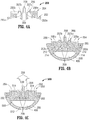
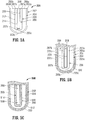
- FIGS. 4A-4C and 5A-5C methods of manufacturing one or more components of an end effector assembly of an energy-based surgical device are described. As can be appreciated in view of the following, these manufacturing methods help ensure proper alignment and spacing between the various components of the end effector assembly, thereby facilitating effective tissue treatment and/or cutting.
- manufacture of a jaw member similar to jaw member 120 is described below with reference to FIGS. 4A-4C and 5A-5C .
- the manufacturing methods provided in accordance with the present disclosure are equally applicable for use in manufacturing an end effector assembly or component thereof of any suitable energy-based surgical device.
- an electrically-conductive substrate 200 (or other suitable substrate configured to energize tissue for treating and/or cutting tissue) is formed.
- substrate 200 may be formed via, for example, stamping, although substrate may alternatively be formed via molding, punching, blanking, embossing, coining, or other suitable method.
- Substrate 200 is formed as a single, integral component and includes: a generally U-shaped outer engagement flange 202 defining first and second side portions 203a, 203b interconnected by an arc-shaped portion 203c; a generally U-shaped tissue-contacting segment 204 extending inwardly from outer engagement flange 202 and defining first and second side portions 205a, 205b interconnected by an arc-shaped portion 205c; a generally U-shaped connector 206 extending inwardly from tissue-contacting segment 204 and defining first and second side portions 207a, 207b interconnected by an arc-shaped portion 207c; and a central member 208 disposed between side portions 207a, 207b and arc-shaped portion 270c of tissue-contact segment 204.
- Central member 208 defines an inner engagement flange 209 extending therefrom
- perforations 212, 214 may be formed in substrate 200 between tissue-contacting segment 204 and connector 206, and between connector 206 and central member 208, respectively.
- substrate 200 once formed (and/or perforated), is engaged to, e.g., retained and supported on, insulative member 300. More specifically substrate 200 may be engaged to insulative member 300 via overmolding insulative member 300 about substrate 200 such that outer flange 202 and inner flange 209 are retained within and surrounded by insulative member 300. Alternatively, substrate 200 may be engaged to insulative member 300 via snap-fitting, adhesion, or any other suitable method. Prior to, in conjunction with, or after engagement of substrate 200 and insulative member 300 to one another, insulative member 300 is engaged about jaw frame 400.
- insulative member 300 may be injection molded about both jaw frame 400 and substrate 200 to simultaneously (or near-simultaneously) engage the components to one another.
- insulative member 300 may be engaged about jaw frame 400, e.g., via snap-fitting, friction fitting, etc., after engagement of insulative member 300 about substrate 200.
- FIGS. 4C and 5C with insulative member 300 engaged about both substrate 200, e.g., via the engagement of outer and inner flanges 202, 209 within member 300, and jaw frame 400, substrate 200 is retained in fixed position and orientation relative to itself and to insulative member 300. In other words, the alignment and spacing of the various portions of substrate 200 is set. At this point, substrate 200 may be partitioned by removing connector 206 without disturbing the set alignment and spacing between the various portions of substrate 200. Removal of connector 206 is facilitated by perforations 212, 214 ( FIGS. 4A, 4B , 5A, and 5B ). With connector 206 removed, as shown in FIGS. 4C and 5C , central member 208 is decoupled from tissue-contacting segment 204. More specifically, upon removal of connector 206, central member 208 and tissue-contacting segment 204 are spaced-apart and insulated from one another via insulative member 300.
- a jaw member 500 including a tissue-contacting plate 514 and energy-based cutting member 530 electrically insulated from one another via an insulating member 560 is provided.
- tissue-contacting plate 514 and energy-based cutting member 530 are properly aligned and spaced relative to one another, thus facilitating effective tissue treatment and/or cutting during use.
- insulating member 560 and outer insulative jaw housing 512 are formed as a single, integral component. However, it is also envisioned that insulating member 560 and outer insulative jaw housing 512 be provided as separate components.
Landscapes
- Health & Medical Sciences (AREA)
- Surgery (AREA)
- Engineering & Computer Science (AREA)
- Life Sciences & Earth Sciences (AREA)
- Biomedical Technology (AREA)
- Otolaryngology (AREA)
- Nuclear Medicine, Radiotherapy & Molecular Imaging (AREA)
- Plasma & Fusion (AREA)
- Physics & Mathematics (AREA)
- Heart & Thoracic Surgery (AREA)
- Medical Informatics (AREA)
- Molecular Biology (AREA)
- Animal Behavior & Ethology (AREA)
- General Health & Medical Sciences (AREA)
- Public Health (AREA)
- Veterinary Medicine (AREA)
- Surgical Instruments (AREA)
Claims (9)
- Verfahren zum Herstellen einer Endeffektoranordnung (100), die einen ersten und einen zweiten ansteuerbaren Abschnitt (204, 208) beinhaltet, konfiguriert, um einem Gewebe Energie zuzuführen, wobei das Verfahren umfasst:Ausbilden eines Substrats (200) mit einem ersten und einem zweiten Substratabschnitt (204, 208), die durch einen Verbinderabschnitt (206) miteinander verbunden sind, wobei das Substrat als eine einzelne integrierte Komponente ausgebildet ist, wobei das Substrat (200) beinhaltet: in Draufsicht einen im Allgemeinen U-förmigen Außeneingriffsflansch (202), der einen ersten und einen zweiten Seitenabschnitt (203a, 203b) definiert, die durch einen bogenförmigen Abschnitt (203c) miteinander verbunden sind; ein im Allgemeinen U-förmiges gewebekontaktierendes Segment (204), das den ersten Substratabschnitt bereitstellt und sich von dem Außeneingriffsflansch (202) nach innen erstreckt und einen ersten und einen zweiten Seitenabschnitt (205a, 205b) definiert, die durch einen bogenförmigen Abschnitt (205c) miteinander verbunden sind; und ein zentrales Element (208), das den zweiten Substratabschnitt bereitstellt, wobei das zentrale Element einen Inneneingriffsflansch (209) definiert, der sich davon erstreckt;Ineingriffbringen des Substrats mit einem isolierenden Element (300); undEntfernen des Verbinderabschnitts des Substrats, um den ersten und den zweiten Substratabschnitt elektrisch voneinander zu isolieren; dadurch gekennzeichnet, dass:in der Draufsicht der Verbinderabschnitt (206) im Allgemeinen U-förmig ist und sich von dem gewebekontaktierenden Segment (204) nach innen erstreckt, wobei der Verbinderabschnitt (206) einen ersten und einen zweiten Seitenabschnitt (207a, 207b) definiert, die durch einen bogenförmigen Abschnitt (207c) miteinander verbunden sind, wobei das zentrale Element (208) des Substrats (200) zwischen dem ersten und dem zweiten Seitenabschnitt (207a, 207b) und dem bogenförmigen Abschnitt (207c) des Verbinders (206) angeordnet ist; unddas Verfahren ferner den Schritt des Perforierens des Substrats (200) umfasst, wobei sowohl der erste als auch der zweite Substratabschnitt (204, 208) auf den Verbinderabschnitt treffen, um das Entfernen des im Allgemeinen U-förmigen Verbinderabschnitts zu erleichtern.
- Verfahren nach Anspruch 1, wobei das Substrat (200) eine elektrisch leitfähige Platte ist.
- Verfahren nach Anspruch 1 oder 2, wobei das isolierende Element (300) ein äußeres isolierendes Gehäuse bildet, das das Substrat und einen isolierenden Abstandshalter trägt, der zwischen dem ersten und dem zweiten Abschnitt angeordnet ist.
- Verfahren nach Anspruch 1, wobei:das Substrat (200) eine leitfähige Platte ist,der erste Abschnitt (204) konfiguriert ist, um einem Gewebe Energie zum Behandeln von Gewebe zuzuführen,der zweite Abschnitt (208) konfiguriert ist, um einem Gewebe Energie zum Schneiden von Gewebe zuzuführen, undder Ausbildungsschritt das Ausbilden der leitfähigen Platte umfasst;das isolierende Element (300) ein isolierendes Gehäuse ist, undder Eingriffsschritt das Ineingriffbringen der Platte mit einem isolierenden Gehäuse umfasst, um ein erstes Backenelement (500) zu bilden.
- Verfahren nach einem vorhergehenden Anspruch, wobei das Substrat (200) durch Stanzen gebildet wird.
- Verfahren nach einem vorhergehenden Anspruch, wobei das Substrat (200) durch Umspritzen mit dem isolierenden Element (300) in Eingriff gebracht wird.
- Verfahren nach einem vorhergehenden Anspruch, das ferner den Schritt des Ineingriffbringens des isolierenden Elements (300), mit dem das Substrat in Eingriff steht, um einen ersten Backenrahmen (400) umfasst.
- Verfahren nach einem vorhergehenden Anspruch, das ferner den Schritt des Verbindens des ersten und des zweiten ansteuerbaren Abschnitts (204, 208) unabhängig voneinander mit einer Energiequelle umfasst.
- Verfahren nach Anspruch 1, wobei der Schritt des Perforierens des Substrats (200) nach dem Schritt des Ausbildens des Substrats durchgeführt wird.
Applications Claiming Priority (2)
| Application Number | Priority Date | Filing Date | Title |
|---|---|---|---|
| US201361829415P | 2013-05-31 | 2013-05-31 | |
| US14/202,145 US9649151B2 (en) | 2013-05-31 | 2014-03-10 | End effector assemblies and methods of manufacturing end effector assemblies for treating and/or cutting tissue |
Publications (2)
| Publication Number | Publication Date |
|---|---|
| EP2807988A1 EP2807988A1 (de) | 2014-12-03 |
| EP2807988B1 true EP2807988B1 (de) | 2020-04-01 |
Family
ID=50771144
Family Applications (1)
| Application Number | Title | Priority Date | Filing Date |
|---|---|---|---|
| EP14169456.2A Active EP2807988B1 (de) | 2013-05-31 | 2014-05-22 | Verfahren zur Herstellung von Endeffektoranordnungen zur Behandlung und/oder zum Schneiden von Gewebe |
Country Status (2)
| Country | Link |
|---|---|
| US (2) | US9649151B2 (de) |
| EP (1) | EP2807988B1 (de) |
Families Citing this family (33)
| Publication number | Priority date | Publication date | Assignee | Title |
|---|---|---|---|---|
| US10172669B2 (en) | 2009-10-09 | 2019-01-08 | Ethicon Llc | Surgical instrument comprising an energy trigger lockout |
| GB2480498A (en) | 2010-05-21 | 2011-11-23 | Ethicon Endo Surgery Inc | Medical device comprising RF circuitry |
| US9421060B2 (en) | 2011-10-24 | 2016-08-23 | Ethicon Endo-Surgery, Llc | Litz wire battery powered device |
| US9649151B2 (en) | 2013-05-31 | 2017-05-16 | Covidien Lp | End effector assemblies and methods of manufacturing end effector assemblies for treating and/or cutting tissue |
| US10111700B2 (en) * | 2013-11-08 | 2018-10-30 | Covidien Lp | Surgical instruments including 3D injection molded electrical circuits and connections |
| US10342601B2 (en) | 2014-04-02 | 2019-07-09 | Covidien Lp | Electrosurgical devices including transverse electrode configurations |
| US10278768B2 (en) | 2014-04-02 | 2019-05-07 | Covidien Lp | Electrosurgical devices including transverse electrode configurations |
| PL2982325T3 (pl) * | 2014-08-04 | 2020-07-13 | Erbe Elektromedizin Gmbh | Sposób wytwarzania ramienia i instrument chirurgiczny z przyrządem mającym ramiona |
| PL3193761T3 (pl) * | 2014-09-15 | 2021-10-18 | Novoxel Ltd. | Sposoby wytwarzania urządzeń do cieplnego parowania i uciskania tkanki |
| US10159524B2 (en) | 2014-12-22 | 2018-12-25 | Ethicon Llc | High power battery powered RF amplifier topology |
| US10314638B2 (en) | 2015-04-07 | 2019-06-11 | Ethicon Llc | Articulating radio frequency (RF) tissue seal with articulating state sensing |
| US10959771B2 (en) | 2015-10-16 | 2021-03-30 | Ethicon Llc | Suction and irrigation sealing grasper |
| US10470790B2 (en) | 2015-12-16 | 2019-11-12 | Ethicon Llc | Surgical instrument with selector |
| US10959806B2 (en) | 2015-12-30 | 2021-03-30 | Ethicon Llc | Energized medical device with reusable handle |
| US10856934B2 (en) | 2016-04-29 | 2020-12-08 | Ethicon Llc | Electrosurgical instrument with electrically conductive gap setting and tissue engaging members |
| US10987156B2 (en) | 2016-04-29 | 2021-04-27 | Ethicon Llc | Electrosurgical instrument with electrically conductive gap setting member and electrically insulative tissue engaging members |
| US10751117B2 (en) | 2016-09-23 | 2020-08-25 | Ethicon Llc | Electrosurgical instrument with fluid diverter |
| US11007003B2 (en) * | 2016-11-17 | 2021-05-18 | Covidien Lp | Surgical instruments and methods of manufacturing surgical instruments for performing tonsillectomy, adenoidectomy, and other surgical procedures |
| US11033325B2 (en) | 2017-02-16 | 2021-06-15 | Cilag Gmbh International | Electrosurgical instrument with telescoping suction port and debris cleaner |
| US10799284B2 (en) | 2017-03-15 | 2020-10-13 | Ethicon Llc | Electrosurgical instrument with textured jaws |
| US11497546B2 (en) | 2017-03-31 | 2022-11-15 | Cilag Gmbh International | Area ratios of patterned coatings on RF electrodes to reduce sticking |
| US10603117B2 (en) | 2017-06-28 | 2020-03-31 | Ethicon Llc | Articulation state detection mechanisms |
| US11033323B2 (en) | 2017-09-29 | 2021-06-15 | Cilag Gmbh International | Systems and methods for managing fluid and suction in electrosurgical systems |
| US11484358B2 (en) | 2017-09-29 | 2022-11-01 | Cilag Gmbh International | Flexible electrosurgical instrument |
| US11490951B2 (en) | 2017-09-29 | 2022-11-08 | Cilag Gmbh International | Saline contact with electrodes |
| KR102755888B1 (ko) * | 2017-12-19 | 2025-01-21 | 인튜어티브 서지컬 오퍼레이션즈 인코포레이티드 | 동시적인 전기수술 봉합 및 절단 |
| US11717338B2 (en) | 2018-09-10 | 2023-08-08 | Jgmg Bengochea, Llc | Bipolar dissector |
| US12053229B2 (en) | 2020-06-30 | 2024-08-06 | Covidien Lp | Vessel sealing instrument with seal plates for directing the flow of energy |
| US12127781B2 (en) | 2020-06-30 | 2024-10-29 | Covidien Lp | Vessel sealing instrument with seal plates for directing the flow of energy |
| US12471982B2 (en) | 2020-12-02 | 2025-11-18 | Cilag Gmbh International | Method for tissue treatment by surgical instrument |
| US12508021B2 (en) | 2021-11-01 | 2025-12-30 | Cilag Gmbh International | Devices, systems, and methods for detecting tissue and foreign objects during a surgical operation |
| US11957342B2 (en) | 2021-11-01 | 2024-04-16 | Cilag Gmbh International | Devices, systems, and methods for detecting tissue and foreign objects during a surgical operation |
| US20240293170A1 (en) * | 2023-03-01 | 2024-09-05 | Cilag Gmbh International | Thermally and mechanically symmetric electrodes for end effectors |
Family Cites Families (164)
| Publication number | Priority date | Publication date | Assignee | Title |
|---|---|---|---|---|
| SU401367A1 (ru) | 1971-10-05 | 1973-10-12 | Тернопольский государственный медицинский институт | Биактивный электрохирургическнп инструмент |
| DE2415263A1 (de) | 1974-03-29 | 1975-10-02 | Aesculap Werke Ag | Chirurgische hf-koagulationssonde |
| DE2514501A1 (de) | 1975-04-03 | 1976-10-21 | Karl Storz | Bipolares coagulationsinstrument fuer endoskope |
| FR2315286A2 (fr) | 1975-06-26 | 1977-01-21 | Lamidey Marcel | Pince a dissequer, hemostatique, haute frequence |
| USD249549S (en) | 1976-10-22 | 1978-09-19 | Aspen Laboratories, Inc. | Electrosurgical handle |
| USD263020S (en) | 1980-01-22 | 1982-02-16 | Rau Iii David M | Retractable knife |
| DE3490633C2 (de) | 1984-01-30 | 1988-06-23 | Cahr Kovskij Ni Skij I Obscej | Bipolares elektrochirurgisches Instrument |
| DE3423356C2 (de) | 1984-06-25 | 1986-06-26 | Berchtold Medizin-Elektronik GmbH & Co, 7200 Tuttlingen | Elektrochirurgisches Hochfrequenz-Schneidinstrument |
| US4657016A (en) | 1984-08-20 | 1987-04-14 | Garito Jon C | Electrosurgical handpiece for blades, needles and forceps |
| USD299413S (en) | 1985-07-17 | 1989-01-17 | The Stanley Works | Folding pocket saw handle |
| USD295893S (en) | 1985-09-25 | 1988-05-24 | Acme United Corporation | Disposable surgical clamp |
| USD295894S (en) | 1985-09-26 | 1988-05-24 | Acme United Corporation | Disposable surgical scissors |
| DE3627221A1 (de) | 1986-01-15 | 1988-02-18 | Siemens Ag | Hf-chirurgiegeraet mit leistungssteuerung vom chirurgie-handgriff aus |
| USD298353S (en) | 1986-05-06 | 1988-11-01 | Vitalmetrics, Inc. | Handle for surgical instrument |
| DE8712328U1 (de) | 1987-09-11 | 1988-02-18 | Jakoubek, Franz, 7201 Emmingen-Liptingen | Endoskopiezange |
| WO1990006763A1 (en) | 1988-12-05 | 1990-06-28 | The Trustees Of Columbia University In The City Of New York | Novel derivatives of cyclosporine a, antibodies directed thereto and uses thereof |
| JP2806511B2 (ja) | 1990-07-31 | 1998-09-30 | 松下電工株式会社 | 合金系焼結体の製法 |
| US5389102A (en) | 1990-09-13 | 1995-02-14 | United States Surgical Corporation | Apparatus and method for subcuticular stapling of body tissue |
| US5190541A (en) | 1990-10-17 | 1993-03-02 | Boston Scientific Corporation | Surgical instrument and method |
| JP2951418B2 (ja) | 1991-02-08 | 1999-09-20 | トキコ株式会社 | 試料液成分分析装置 |
| US5330471A (en) | 1991-06-07 | 1994-07-19 | Hemostatic Surgery Corporation | Bi-polar electrosurgical endoscopic instruments and methods of use |
| USD348930S (en) | 1991-10-11 | 1994-07-19 | Ethicon, Inc. | Endoscopic stapler |
| JPH0630945B2 (ja) | 1991-12-20 | 1994-04-27 | 株式会社サトー | カーボンリボンの蛇行防止巻取機構 |
| JPH0630945A (ja) | 1992-05-19 | 1994-02-08 | Olympus Optical Co Ltd | 縫合器 |
| DE4220407C1 (de) * | 1992-06-19 | 1993-11-25 | Ethicon Gmbh | Verpackung mit Nahtmaterial für chirurgische Zwecke |
| USD349341S (en) | 1992-10-28 | 1994-08-02 | Microsurge, Inc. | Endoscopic grasper |
| DE4303882C2 (de) | 1993-02-10 | 1995-02-09 | Kernforschungsz Karlsruhe | Kombinationsinstrument zum Trennen und Koagulieren für die minimal invasive Chirurgie |
| JP3390041B2 (ja) | 1993-04-05 | 2003-03-24 | オリンパス光学工業株式会社 | 鉗 子 |
| GB9309142D0 (en) | 1993-05-04 | 1993-06-16 | Gyrus Medical Ltd | Laparoscopic instrument |
| USD343453S (en) | 1993-05-05 | 1994-01-18 | Laparomed Corporation | Handle for laparoscopic surgical instrument |
| USD354564S (en) | 1993-06-25 | 1995-01-17 | Richard-Allan Medical Industries, Inc. | Surgical clip applier |
| US5693051A (en) | 1993-07-22 | 1997-12-02 | Ethicon Endo-Surgery, Inc. | Electrosurgical hemostatic device with adaptive electrodes |
| US5688270A (en) | 1993-07-22 | 1997-11-18 | Ethicon Endo-Surgery,Inc. | Electrosurgical hemostatic device with recessed and/or offset electrodes |
| GB9322464D0 (en) | 1993-11-01 | 1993-12-22 | Gyrus Medical Ltd | Electrosurgical apparatus |
| USD358887S (en) | 1993-12-02 | 1995-05-30 | Cobot Medical Corporation | Combined cutting and coagulating forceps |
| DE4403252A1 (de) | 1994-02-03 | 1995-08-10 | Michael Hauser | Instrumentenschaft für die minimalinvasive Chirurgie |
| GB9413070D0 (en) | 1994-06-29 | 1994-08-17 | Gyrus Medical Ltd | Electrosurgical apparatus |
| USD384413S (en) | 1994-10-07 | 1997-09-30 | United States Surgical Corporation | Endoscopic suturing instrument |
| GB9425781D0 (en) | 1994-12-21 | 1995-02-22 | Gyrus Medical Ltd | Electrosurgical instrument |
| DE19506363A1 (de) | 1995-02-24 | 1996-08-29 | Frost Lore Geb Haupt | Verfahren zur nicht-invasiven Thermometrie in Organen unter medizinischen Hyperthermie- und Koagulationsbedingungen |
| JPH08289895A (ja) | 1995-04-21 | 1996-11-05 | Olympus Optical Co Ltd | 縫合器 |
| DE19515914C1 (de) | 1995-05-02 | 1996-07-25 | Aesculap Ag | Zangen- oder scherenförmiges chirurgisches Instrument |
| JPH09538A (ja) | 1995-06-21 | 1997-01-07 | Fuji Photo Optical Co Ltd | 高周波処置具 |
| US6293942B1 (en) | 1995-06-23 | 2001-09-25 | Gyrus Medical Limited | Electrosurgical generator method |
| JPH1024051A (ja) | 1995-09-20 | 1998-01-27 | Olympus Optical Co Ltd | 切離機能付凝固鉗子 |
| USH1745H (en) | 1995-09-29 | 1998-08-04 | Paraschac; Joseph F. | Electrosurgical clamping device with insulation limited bipolar electrode |
| AU703455B2 (en) | 1995-10-20 | 1999-03-25 | Ethicon Endo-Surgery, Inc. | Self protecting knife for curved jaw surgical instruments |
| US5673842A (en) | 1996-03-05 | 1997-10-07 | Ethicon Endo-Surgery | Surgical stapler with locking mechanism |
| DE19608716C1 (de) | 1996-03-06 | 1997-04-17 | Aesculap Ag | Bipolares chirurgisches Faßinstrument |
| USD408018S (en) | 1996-03-12 | 1999-04-13 | Mcnaughton Patrick J | Switch guard |
| USD416089S (en) | 1996-04-08 | 1999-11-02 | Richard-Allan Medical Industries, Inc. | Endoscopic linear stapling and dividing surgical instrument |
| DE29616210U1 (de) | 1996-09-18 | 1996-11-14 | Olympus Winter & Ibe Gmbh, 22045 Hamburg | Handhabe für chirurgische Instrumente |
| US5923475A (en) | 1996-11-27 | 1999-07-13 | Eastman Kodak Company | Laser printer using a fly's eye integrator |
| JP3836551B2 (ja) | 1996-12-04 | 2006-10-25 | ペンタックス株式会社 | 内視鏡用ホットバイオプシー鉗子 |
| US5891142A (en) | 1996-12-06 | 1999-04-06 | Eggers & Associates, Inc. | Electrosurgical forceps |
| USH1904H (en) | 1997-05-14 | 2000-10-03 | Ethicon Endo-Surgery, Inc. | Electrosurgical hemostatic method and device |
| USH2037H1 (en) | 1997-05-14 | 2002-07-02 | David C. Yates | Electrosurgical hemostatic device including an anvil |
| JP3986127B2 (ja) | 1997-08-06 | 2007-10-03 | オリンパス株式会社 | 内視鏡下手術器械 |
| DE19738457B4 (de) | 1997-09-03 | 2009-01-02 | Celon Ag Medical Instruments | Verfahren und Vorrichtung für die In-vivo-Tiefenkoagulation biologischer Gewebevolumina bei gleichzeitiger Schonung der Gewebeoberfläche mit hochfrequentem Wechselstrom |
| US5980510A (en) | 1997-10-10 | 1999-11-09 | Ethicon Endo-Surgery, Inc. | Ultrasonic clamp coagulator apparatus having improved clamp arm pivot mount |
| USD402028S (en) | 1997-10-10 | 1998-12-01 | Invasatec, Inc. | Hand controller for medical system |
| DE19751108A1 (de) | 1997-11-18 | 1999-05-20 | Beger Frank Michael Dipl Desig | Elektrochirurgisches Operationswerkzeug |
| JPH11169381A (ja) | 1997-12-15 | 1999-06-29 | Olympus Optical Co Ltd | 高周波処置具 |
| EP0923907A1 (de) | 1997-12-19 | 1999-06-23 | Gyrus Medical Limited | Elektrochirurgisches Instrument |
| JP4225624B2 (ja) | 1998-08-27 | 2009-02-18 | オリンパス株式会社 | 高周波処置装置 |
| USD424694S (en) | 1998-10-23 | 2000-05-09 | Sherwood Services Ag | Forceps |
| USD449886S1 (en) | 1998-10-23 | 2001-10-30 | Sherwood Services Ag | Forceps with disposable electrode |
| CA2347014C (en) | 1998-10-23 | 2011-01-04 | Sherwood Services Ag | Open vessel sealing forceps with disposable electrodes |
| USD425201S (en) | 1998-10-23 | 2000-05-16 | Sherwood Services Ag | Disposable electrode assembly |
| DE19858512C1 (de) | 1998-12-18 | 2000-05-25 | Storz Karl Gmbh & Co Kg | Bipolares medizinisches Instrument |
| DE19915061A1 (de) | 1999-04-01 | 2000-10-26 | Erbe Elektromedizin | Chirurgisches Instrument |
| GB9911954D0 (en) | 1999-05-21 | 1999-07-21 | Gyrus Medical Ltd | Electrosurgery system and instrument |
| GB9911956D0 (en) | 1999-05-21 | 1999-07-21 | Gyrus Medical Ltd | Electrosurgery system and method |
| GB9912625D0 (en) | 1999-05-28 | 1999-07-28 | Gyrus Medical Ltd | An electrosurgical generator and system |
| GB9912627D0 (en) | 1999-05-28 | 1999-07-28 | Gyrus Medical Ltd | An electrosurgical instrument |
| GB9913652D0 (en) | 1999-06-11 | 1999-08-11 | Gyrus Medical Ltd | An electrosurgical generator |
| JP2001003400A (ja) | 1999-06-21 | 2001-01-09 | Sumitomo Constr Mach Co Ltd | 油圧ショベルのモニター装置 |
| DE19940689A1 (de) | 1999-08-27 | 2001-04-05 | Storz Karl Gmbh & Co Kg | Bipolares medizinisches Instrument |
| USD465281S1 (en) | 1999-09-21 | 2002-11-05 | Karl Storz Gmbh & Co. Kg | Endoscopic medical instrument |
| DE19946527C1 (de) | 1999-09-28 | 2001-07-12 | Storz Karl Gmbh & Co Kg | Medizinisches bipolares Instrument zum Fassen, Koagulieren und Schneiden von Gewebe |
| JP4315557B2 (ja) | 2000-01-12 | 2009-08-19 | オリンパス株式会社 | 医療用処置具 |
| DE10003020C2 (de) | 2000-01-25 | 2001-12-06 | Aesculap Ag & Co Kg | Bipolares Faßinstrument |
| DE10031773B4 (de) | 2000-05-04 | 2007-11-29 | Erbe Elektromedizin Gmbh | Chirurgisches Greifinstrument, insbesondere Pinzette oder Zange |
| DE10027727C1 (de) | 2000-06-03 | 2001-12-06 | Aesculap Ag & Co Kg | Scheren- oder zangenförmiges chirurgisches Instrument |
| DE10045375C2 (de) | 2000-09-14 | 2002-10-24 | Aesculap Ag & Co Kg | Medizinisches Instrument |
| AU2002246923A1 (en) | 2000-10-20 | 2002-07-30 | Onux Medical, Inc. | Surgical suturing instrument and method of use |
| JP3523839B2 (ja) | 2000-10-30 | 2004-04-26 | オリンパス株式会社 | 手術器械 |
| USD453923S1 (en) | 2000-11-16 | 2002-02-26 | Carling Technologies, Inc. | Electrical rocker switch guard |
| DE10061278B4 (de) | 2000-12-08 | 2004-09-16 | GFD-Gesellschaft für Diamantprodukte mbH | Instrument für chirurgische Zwecke |
| US20020111624A1 (en) | 2001-01-26 | 2002-08-15 | Witt David A. | Coagulating electrosurgical instrument with tissue dam |
| DE20121161U1 (de) | 2001-01-31 | 2002-04-04 | Olympus Winter & Ibe Gmbh, 22045 Hamburg | Endoskopisches Instrument |
| USD454951S1 (en) | 2001-02-27 | 2002-03-26 | Visionary Biomedical, Inc. | Steerable catheter |
| USD466209S1 (en) | 2001-02-27 | 2002-11-26 | Visionary Biomedical, Inc. | Steerable catheter |
| USD457959S1 (en) | 2001-04-06 | 2002-05-28 | Sherwood Services Ag | Vessel sealer |
| USD457958S1 (en) | 2001-04-06 | 2002-05-28 | Sherwood Services Ag | Vessel sealer and divider |
| FR2828248B1 (fr) | 2001-08-02 | 2003-11-14 | Peugeot Citroen Automobiles Sa | Axe de liaison pivot entre deux pieces |
| JP2003116871A (ja) | 2001-10-16 | 2003-04-22 | Olympus Optical Co Ltd | 処置具 |
| US6676660B2 (en) | 2002-01-23 | 2004-01-13 | Ethicon Endo-Surgery, Inc. | Feedback light apparatus and method for use with an electrosurgical instrument |
| JP4459814B2 (ja) | 2002-10-04 | 2010-04-28 | コヴィディエン アクチェンゲゼルシャフト | 組織をシールし、そして切断するための電極アセンブリおよび組織をシールし、そして切断することを実施するための方法 |
| US7270664B2 (en) | 2002-10-04 | 2007-09-18 | Sherwood Services Ag | Vessel sealing instrument with electrical cutting mechanism |
| US7276068B2 (en) | 2002-10-04 | 2007-10-02 | Sherwood Services Ag | Vessel sealing instrument with electrical cutting mechanism |
| US7931649B2 (en) | 2002-10-04 | 2011-04-26 | Tyco Healthcare Group Lp | Vessel sealing instrument with electrical cutting mechanism |
| JP2003175052A (ja) | 2002-11-01 | 2003-06-24 | Olympus Optical Co Ltd | 凝固処置具 |
| USD493888S1 (en) | 2003-02-04 | 2004-08-03 | Sherwood Services Ag | Electrosurgical pencil with pistol grip |
| USD496997S1 (en) | 2003-05-15 | 2004-10-05 | Sherwood Services Ag | Vessel sealer and divider |
| USD499181S1 (en) | 2003-05-15 | 2004-11-30 | Sherwood Services Ag | Handle for a vessel sealer and divider |
| USD502994S1 (en) | 2003-05-21 | 2005-03-15 | Blake, Iii Joseph W | Repeating multi-clip applier |
| US7150749B2 (en) | 2003-06-13 | 2006-12-19 | Sherwood Services Ag | Vessel sealer and divider having elongated knife stroke and safety cutting mechanism |
| US7150097B2 (en) | 2003-06-13 | 2006-12-19 | Sherwood Services Ag | Method of manufacturing jaw assembly for vessel sealer and divider |
| USD545432S1 (en) | 2003-08-08 | 2007-06-26 | Olympus Corporation | Distal portion of hemostatic forceps for endoscope |
| USD509297S1 (en) | 2003-10-17 | 2005-09-06 | Tyco Healthcare Group, Lp | Surgical instrument |
| US7442193B2 (en) | 2003-11-20 | 2008-10-28 | Covidien Ag | Electrically conductive/insulative over-shoe for tissue fusion |
| JP4624697B2 (ja) | 2004-03-12 | 2011-02-02 | オリンパス株式会社 | 手術用処置具 |
| USD541938S1 (en) | 2004-04-09 | 2007-05-01 | Sherwood Services Ag | Open vessel sealer with mechanical cutter |
| JP2005312807A (ja) | 2004-04-30 | 2005-11-10 | Olympus Corp | エネルギー治療装置 |
| DE102004026179B4 (de) | 2004-05-14 | 2009-01-22 | Erbe Elektromedizin Gmbh | Elektrochirurgisches Instrument |
| USD533942S1 (en) | 2004-06-30 | 2006-12-19 | Sherwood Services Ag | Open vessel sealer with mechanical cutter |
| JP2006015078A (ja) | 2004-07-05 | 2006-01-19 | Olympus Corp | 医療用装置 |
| DE102004040959B4 (de) | 2004-08-24 | 2008-12-24 | Erbe Elektromedizin Gmbh | Chirurgisches Instrument |
| USD541418S1 (en) | 2004-10-06 | 2007-04-24 | Sherwood Services Ag | Lung sealing device |
| USD525361S1 (en) | 2004-10-06 | 2006-07-18 | Sherwood Services Ag | Hemostat style elongated dissecting and dividing instrument |
| USD531311S1 (en) | 2004-10-06 | 2006-10-31 | Sherwood Services Ag | Pistol grip style elongated dissecting and dividing instrument |
| USD535027S1 (en) | 2004-10-06 | 2007-01-09 | Sherwood Services Ag | Low profile vessel sealing and cutting mechanism |
| USD567943S1 (en) | 2004-10-08 | 2008-04-29 | Sherwood Services Ag | Over-ratchet safety for a vessel sealing instrument |
| USD533274S1 (en) | 2004-10-12 | 2006-12-05 | Allegiance Corporation | Handle for surgical suction-irrigation device |
| USD582038S1 (en) | 2004-10-13 | 2008-12-02 | Medtronic, Inc. | Transurethral needle ablation device |
| USD564662S1 (en) | 2004-10-13 | 2008-03-18 | Sherwood Services Ag | Hourglass-shaped knife for electrosurgical forceps |
| USD538932S1 (en) | 2005-06-30 | 2007-03-20 | Medical Action Industries Inc. | Surgical needle holder |
| CA2561034C (en) | 2005-09-30 | 2014-12-09 | Sherwood Services Ag | Flexible endoscopic catheter with an end effector for coagulating and transfecting tissue |
| USD541611S1 (en) | 2006-01-26 | 2007-05-01 | Robert Bosch Gmbh | Cordless screwdriver |
| USD547154S1 (en) | 2006-09-08 | 2007-07-24 | Winsource Industries Limited | Rotary driving tool |
| ATE544412T1 (de) | 2006-10-05 | 2012-02-15 | Erbe Elektromedizin | Rohrschaftinstrument |
| USD649249S1 (en) | 2007-02-15 | 2011-11-22 | Tyco Healthcare Group Lp | End effectors of an elongated dissecting and dividing instrument |
| USD575395S1 (en) | 2007-02-15 | 2008-08-19 | Tyco Healthcare Group Lp | Hemostat style elongated dissecting and dividing instrument |
| USD575401S1 (en) | 2007-06-12 | 2008-08-19 | Tyco Healthcare Group Lp | Vessel sealer |
| DE202007009318U1 (de) | 2007-06-26 | 2007-08-30 | Aesculap Ag & Co. Kg | Chirurgisches Instrument |
| DE202007009317U1 (de) | 2007-06-26 | 2007-08-30 | Aesculap Ag & Co. Kg | Chirurgisches Instrument |
| DE202007009165U1 (de) | 2007-06-29 | 2007-08-30 | Kls Martin Gmbh + Co. Kg | Chirurgisches Instrument |
| DE202007016233U1 (de) | 2007-11-20 | 2008-01-31 | Aesculap Ag & Co. Kg | Chirurgische Pinzette |
| DE102008018406B3 (de) | 2008-04-10 | 2009-07-23 | Bowa-Electronic Gmbh & Co. Kg | Elektrochirurgisches Gerät |
| CN201299462Y (zh) | 2008-10-28 | 2009-09-02 | 宋洪海 | 一种多层金属复合炊锅 |
| USD621503S1 (en) | 2009-04-28 | 2010-08-10 | Tyco Healthcare Group Ip | Pistol grip laparoscopic sealing and dissection device |
| USD618798S1 (en) | 2009-05-13 | 2010-06-29 | Tyco Healthcare Group Lp | Vessel sealing jaw seal plate |
| USD617902S1 (en) | 2009-05-13 | 2010-06-15 | Tyco Healthcare Group Lp | End effector tip with undercut top jaw |
| USD617900S1 (en) | 2009-05-13 | 2010-06-15 | Tyco Healthcare Group Lp | End effector tip with undercut bottom jaw |
| USD649643S1 (en) | 2009-05-13 | 2011-11-29 | Tyco Healthcare Group Lp | End effector with a rounded tip |
| USD617901S1 (en) | 2009-05-13 | 2010-06-15 | Tyco Healthcare Group Lp | End effector chamfered tip |
| USD617903S1 (en) | 2009-05-13 | 2010-06-15 | Tyco Healthcare Group Lp | End effector pointed tip |
| USD630324S1 (en) | 2009-08-05 | 2011-01-04 | Tyco Healthcare Group Lp | Dissecting surgical jaw |
| DE102009037614A1 (de) | 2009-08-14 | 2011-02-24 | Erbe Elektromedizin Gmbh | Elektrochirurgisches Instrument |
| US8679115B2 (en) | 2009-08-19 | 2014-03-25 | Covidien Lp | Electrical cutting and vessel sealing jaw members |
| USD627462S1 (en) | 2009-09-09 | 2010-11-16 | Tyco Healthcare Group Lp | Knife channel of a jaw device |
| US8266783B2 (en) | 2009-09-28 | 2012-09-18 | Tyco Healthcare Group Lp | Method and system for manufacturing electrosurgical seal plates |
| US8112871B2 (en) | 2009-09-28 | 2012-02-14 | Tyco Healthcare Group Lp | Method for manufacturing electrosurgical seal plates |
| USD628289S1 (en) | 2009-11-30 | 2010-11-30 | Tyco Healthcare Group Lp | Surgical instrument handle |
| USD628290S1 (en) | 2009-11-30 | 2010-11-30 | Tyco Healthcare Group Lp | Surgical instrument handle |
| JP5579427B2 (ja) | 2009-12-14 | 2014-08-27 | 中国電力株式会社 | 間接活線作業用具支持装置 |
| USD661394S1 (en) | 2011-02-24 | 2012-06-05 | Tyco Healthcare Group Lp | Device jaw |
| US9381059B2 (en) | 2011-04-05 | 2016-07-05 | Covidien Lp | Electrically-insulative hinge for electrosurgical jaw assembly, bipolar forceps including same, and methods of jaw-assembly alignment using fastened electrically-insulative hinge |
| US8968307B2 (en) | 2011-08-18 | 2015-03-03 | Covidien Lp | Surgical forceps |
| JP6030945B2 (ja) | 2012-12-20 | 2016-11-24 | 日本電信電話株式会社 | 視聴者映像表示制御装置、視聴者映像表示制御方法、および視聴者映像表示制御プログラム |
| JP6121797B2 (ja) | 2013-05-21 | 2017-04-26 | 株式会社オーク製作所 | ランプ用保護カバー装置、カバー装置付ランプ、及びランプのランプホルダに対する取り付け方法 |
| US9649151B2 (en) | 2013-05-31 | 2017-05-16 | Covidien Lp | End effector assemblies and methods of manufacturing end effector assemblies for treating and/or cutting tissue |
| CN104032737B (zh) | 2014-05-21 | 2016-05-04 | 苏州市能工基础工程有限责任公司 | 压力分散型扩大头锚杆的施工方法及结构 |
-
2014
- 2014-03-10 US US14/202,145 patent/US9649151B2/en active Active
- 2014-05-22 EP EP14169456.2A patent/EP2807988B1/de active Active
-
2017
- 2017-05-03 US US15/585,409 patent/US10245103B2/en not_active Expired - Fee Related
Non-Patent Citations (1)
| Title |
|---|
| None * |
Also Published As
| Publication number | Publication date |
|---|---|
| US20140353869A1 (en) | 2014-12-04 |
| US9649151B2 (en) | 2017-05-16 |
| EP2807988A1 (de) | 2014-12-03 |
| US10245103B2 (en) | 2019-04-02 |
| US20170231688A1 (en) | 2017-08-17 |
Similar Documents
| Publication | Publication Date | Title |
|---|---|---|
| EP2807988B1 (de) | Verfahren zur Herstellung von Endeffektoranordnungen zur Behandlung und/oder zum Schneiden von Gewebe | |
| US12048476B2 (en) | Surgical instrument with switch activation control | |
| US20240315759A1 (en) | Surgical instrument | |
| US10588651B2 (en) | Surgical instrument with stamped double-flange jaws | |
| US9113889B2 (en) | Method of manufacturing an end effector assembly | |
| US10702332B2 (en) | Gap control via overmold teeth and hard stops | |
| US10070916B2 (en) | Surgical instrument with system and method for springing open jaw members | |
| US9265566B2 (en) | Surgical instrument | |
| US9265569B2 (en) | Method of manufacturing an electrosurgical forceps | |
| EP1852079B1 (de) | Einweghandschalter für eine Zange zum Versiegeln von offenen Gefäßen | |
| US10231772B2 (en) | Wire retention unit for a surgical instrument | |
| US8333765B2 (en) | Vessel sealing instrument with electrical cutting mechanism | |
| US9113882B2 (en) | Method of manufacturing an electrosurgical instrument |
Legal Events
| Date | Code | Title | Description |
|---|---|---|---|
| PUAI | Public reference made under article 153(3) epc to a published international application that has entered the european phase |
Free format text: ORIGINAL CODE: 0009012 |
|
| 17P | Request for examination filed |
Effective date: 20140522 |
|
| AK | Designated contracting states |
Kind code of ref document: A1 Designated state(s): AL AT BE BG CH CY CZ DE DK EE ES FI FR GB GR HR HU IE IS IT LI LT LU LV MC MK MT NL NO PL PT RO RS SE SI SK SM TR |
|
| AX | Request for extension of the european patent |
Extension state: BA ME |
|
| R17P | Request for examination filed (corrected) |
Effective date: 20150522 |
|
| RBV | Designated contracting states (corrected) |
Designated state(s): AL AT BE BG CH CY CZ DE DK EE ES FI FR GB GR HR HU IE IS IT LI LT LU LV MC MK MT NL NO PL PT RO RS SE SI SK SM TR |
|
| STAA | Information on the status of an ep patent application or granted ep patent |
Free format text: STATUS: EXAMINATION IS IN PROGRESS |
|
| 17Q | First examination report despatched |
Effective date: 20180614 |
|
| GRAP | Despatch of communication of intention to grant a patent |
Free format text: ORIGINAL CODE: EPIDOSNIGR1 |
|
| STAA | Information on the status of an ep patent application or granted ep patent |
Free format text: STATUS: GRANT OF PATENT IS INTENDED |
|
| INTG | Intention to grant announced |
Effective date: 20191023 |
|
| GRAS | Grant fee paid |
Free format text: ORIGINAL CODE: EPIDOSNIGR3 |
|
| GRAA | (expected) grant |
Free format text: ORIGINAL CODE: 0009210 |
|
| STAA | Information on the status of an ep patent application or granted ep patent |
Free format text: STATUS: THE PATENT HAS BEEN GRANTED |
|
| AK | Designated contracting states |
Kind code of ref document: B1 Designated state(s): AL AT BE BG CH CY CZ DE DK EE ES FI FR GB GR HR HU IE IS IT LI LT LU LV MC MK MT NL NO PL PT RO RS SE SI SK SM TR |
|
| REG | Reference to a national code |
Ref country code: GB Ref legal event code: FG4D |
|
| REG | Reference to a national code |
Ref country code: CH Ref legal event code: EP Ref country code: AT Ref legal event code: REF Ref document number: 1250349 Country of ref document: AT Kind code of ref document: T Effective date: 20200415 |
|
| REG | Reference to a national code |
Ref country code: DE Ref legal event code: R096 Ref document number: 602014063055 Country of ref document: DE |
|
| REG | Reference to a national code |
Ref country code: IE Ref legal event code: FG4D |
|
| PG25 | Lapsed in a contracting state [announced via postgrant information from national office to epo] |
Ref country code: BG Free format text: LAPSE BECAUSE OF FAILURE TO SUBMIT A TRANSLATION OF THE DESCRIPTION OR TO PAY THE FEE WITHIN THE PRESCRIBED TIME-LIMIT Effective date: 20200701 |
|
| REG | Reference to a national code |
Ref country code: NL Ref legal event code: MP Effective date: 20200401 |
|
| REG | Reference to a national code |
Ref country code: LT Ref legal event code: MG4D |
|
| PG25 | Lapsed in a contracting state [announced via postgrant information from national office to epo] |
Ref country code: CZ Free format text: LAPSE BECAUSE OF FAILURE TO SUBMIT A TRANSLATION OF THE DESCRIPTION OR TO PAY THE FEE WITHIN THE PRESCRIBED TIME-LIMIT Effective date: 20200401 Ref country code: NL Free format text: LAPSE BECAUSE OF FAILURE TO SUBMIT A TRANSLATION OF THE DESCRIPTION OR TO PAY THE FEE WITHIN THE PRESCRIBED TIME-LIMIT Effective date: 20200401 Ref country code: FI Free format text: LAPSE BECAUSE OF FAILURE TO SUBMIT A TRANSLATION OF THE DESCRIPTION OR TO PAY THE FEE WITHIN THE PRESCRIBED TIME-LIMIT Effective date: 20200401 Ref country code: NO Free format text: LAPSE BECAUSE OF FAILURE TO SUBMIT A TRANSLATION OF THE DESCRIPTION OR TO PAY THE FEE WITHIN THE PRESCRIBED TIME-LIMIT Effective date: 20200701 Ref country code: PT Free format text: LAPSE BECAUSE OF FAILURE TO SUBMIT A TRANSLATION OF THE DESCRIPTION OR TO PAY THE FEE WITHIN THE PRESCRIBED TIME-LIMIT Effective date: 20200817 Ref country code: LT Free format text: LAPSE BECAUSE OF FAILURE TO SUBMIT A TRANSLATION OF THE DESCRIPTION OR TO PAY THE FEE WITHIN THE PRESCRIBED TIME-LIMIT Effective date: 20200401 Ref country code: IS Free format text: LAPSE BECAUSE OF FAILURE TO SUBMIT A TRANSLATION OF THE DESCRIPTION OR TO PAY THE FEE WITHIN THE PRESCRIBED TIME-LIMIT Effective date: 20200801 Ref country code: SE Free format text: LAPSE BECAUSE OF FAILURE TO SUBMIT A TRANSLATION OF THE DESCRIPTION OR TO PAY THE FEE WITHIN THE PRESCRIBED TIME-LIMIT Effective date: 20200401 Ref country code: GR Free format text: LAPSE BECAUSE OF FAILURE TO SUBMIT A TRANSLATION OF THE DESCRIPTION OR TO PAY THE FEE WITHIN THE PRESCRIBED TIME-LIMIT Effective date: 20200702 |
|
| REG | Reference to a national code |
Ref country code: AT Ref legal event code: MK05 Ref document number: 1250349 Country of ref document: AT Kind code of ref document: T Effective date: 20200401 |
|
| PG25 | Lapsed in a contracting state [announced via postgrant information from national office to epo] |
Ref country code: RS Free format text: LAPSE BECAUSE OF FAILURE TO SUBMIT A TRANSLATION OF THE DESCRIPTION OR TO PAY THE FEE WITHIN THE PRESCRIBED TIME-LIMIT Effective date: 20200401 Ref country code: LV Free format text: LAPSE BECAUSE OF FAILURE TO SUBMIT A TRANSLATION OF THE DESCRIPTION OR TO PAY THE FEE WITHIN THE PRESCRIBED TIME-LIMIT Effective date: 20200401 Ref country code: HR Free format text: LAPSE BECAUSE OF FAILURE TO SUBMIT A TRANSLATION OF THE DESCRIPTION OR TO PAY THE FEE WITHIN THE PRESCRIBED TIME-LIMIT Effective date: 20200401 |
|
| PG25 | Lapsed in a contracting state [announced via postgrant information from national office to epo] |
Ref country code: AL Free format text: LAPSE BECAUSE OF FAILURE TO SUBMIT A TRANSLATION OF THE DESCRIPTION OR TO PAY THE FEE WITHIN THE PRESCRIBED TIME-LIMIT Effective date: 20200401 |
|
| REG | Reference to a national code |
Ref country code: DE Ref legal event code: R097 Ref document number: 602014063055 Country of ref document: DE |
|
| PG25 | Lapsed in a contracting state [announced via postgrant information from national office to epo] |
Ref country code: SM Free format text: LAPSE BECAUSE OF FAILURE TO SUBMIT A TRANSLATION OF THE DESCRIPTION OR TO PAY THE FEE WITHIN THE PRESCRIBED TIME-LIMIT Effective date: 20200401 Ref country code: IT Free format text: LAPSE BECAUSE OF FAILURE TO SUBMIT A TRANSLATION OF THE DESCRIPTION OR TO PAY THE FEE WITHIN THE PRESCRIBED TIME-LIMIT Effective date: 20200401 Ref country code: AT Free format text: LAPSE BECAUSE OF FAILURE TO SUBMIT A TRANSLATION OF THE DESCRIPTION OR TO PAY THE FEE WITHIN THE PRESCRIBED TIME-LIMIT Effective date: 20200401 Ref country code: EE Free format text: LAPSE BECAUSE OF FAILURE TO SUBMIT A TRANSLATION OF THE DESCRIPTION OR TO PAY THE FEE WITHIN THE PRESCRIBED TIME-LIMIT Effective date: 20200401 Ref country code: RO Free format text: LAPSE BECAUSE OF FAILURE TO SUBMIT A TRANSLATION OF THE DESCRIPTION OR TO PAY THE FEE WITHIN THE PRESCRIBED TIME-LIMIT Effective date: 20200401 Ref country code: CH Free format text: LAPSE BECAUSE OF NON-PAYMENT OF DUE FEES Effective date: 20200531 Ref country code: ES Free format text: LAPSE BECAUSE OF FAILURE TO SUBMIT A TRANSLATION OF THE DESCRIPTION OR TO PAY THE FEE WITHIN THE PRESCRIBED TIME-LIMIT Effective date: 20200401 Ref country code: LI Free format text: LAPSE BECAUSE OF NON-PAYMENT OF DUE FEES Effective date: 20200531 Ref country code: DK Free format text: LAPSE BECAUSE OF FAILURE TO SUBMIT A TRANSLATION OF THE DESCRIPTION OR TO PAY THE FEE WITHIN THE PRESCRIBED TIME-LIMIT Effective date: 20200401 Ref country code: MC Free format text: LAPSE BECAUSE OF FAILURE TO SUBMIT A TRANSLATION OF THE DESCRIPTION OR TO PAY THE FEE WITHIN THE PRESCRIBED TIME-LIMIT Effective date: 20200401 |
|
| PLBE | No opposition filed within time limit |
Free format text: ORIGINAL CODE: 0009261 |
|
| STAA | Information on the status of an ep patent application or granted ep patent |
Free format text: STATUS: NO OPPOSITION FILED WITHIN TIME LIMIT |
|
| PG25 | Lapsed in a contracting state [announced via postgrant information from national office to epo] |
Ref country code: PL Free format text: LAPSE BECAUSE OF FAILURE TO SUBMIT A TRANSLATION OF THE DESCRIPTION OR TO PAY THE FEE WITHIN THE PRESCRIBED TIME-LIMIT Effective date: 20200401 Ref country code: SK Free format text: LAPSE BECAUSE OF FAILURE TO SUBMIT A TRANSLATION OF THE DESCRIPTION OR TO PAY THE FEE WITHIN THE PRESCRIBED TIME-LIMIT Effective date: 20200401 |
|
| 26N | No opposition filed |
Effective date: 20210112 |
|
| REG | Reference to a national code |
Ref country code: BE Ref legal event code: MM Effective date: 20200531 |
|
| PG25 | Lapsed in a contracting state [announced via postgrant information from national office to epo] |
Ref country code: LU Free format text: LAPSE BECAUSE OF NON-PAYMENT OF DUE FEES Effective date: 20200522 |
|
| PG25 | Lapsed in a contracting state [announced via postgrant information from national office to epo] |
Ref country code: BE Free format text: LAPSE BECAUSE OF NON-PAYMENT OF DUE FEES Effective date: 20200531 Ref country code: SI Free format text: LAPSE BECAUSE OF FAILURE TO SUBMIT A TRANSLATION OF THE DESCRIPTION OR TO PAY THE FEE WITHIN THE PRESCRIBED TIME-LIMIT Effective date: 20200401 |
|
| PG25 | Lapsed in a contracting state [announced via postgrant information from national office to epo] |
Ref country code: TR Free format text: LAPSE BECAUSE OF FAILURE TO SUBMIT A TRANSLATION OF THE DESCRIPTION OR TO PAY THE FEE WITHIN THE PRESCRIBED TIME-LIMIT Effective date: 20200401 Ref country code: MT Free format text: LAPSE BECAUSE OF FAILURE TO SUBMIT A TRANSLATION OF THE DESCRIPTION OR TO PAY THE FEE WITHIN THE PRESCRIBED TIME-LIMIT Effective date: 20200401 Ref country code: CY Free format text: LAPSE BECAUSE OF FAILURE TO SUBMIT A TRANSLATION OF THE DESCRIPTION OR TO PAY THE FEE WITHIN THE PRESCRIBED TIME-LIMIT Effective date: 20200401 |
|
| PG25 | Lapsed in a contracting state [announced via postgrant information from national office to epo] |
Ref country code: MK Free format text: LAPSE BECAUSE OF FAILURE TO SUBMIT A TRANSLATION OF THE DESCRIPTION OR TO PAY THE FEE WITHIN THE PRESCRIBED TIME-LIMIT Effective date: 20200401 |
|
| PGFP | Annual fee paid to national office [announced via postgrant information from national office to epo] |
Ref country code: IE Payment date: 20220421 Year of fee payment: 9 Ref country code: GB Payment date: 20220426 Year of fee payment: 9 Ref country code: FR Payment date: 20220421 Year of fee payment: 9 Ref country code: DE Payment date: 20220420 Year of fee payment: 9 |
|
| REG | Reference to a national code |
Ref country code: DE Ref legal event code: R119 Ref document number: 602014063055 Country of ref document: DE |
|
| GBPC | Gb: european patent ceased through non-payment of renewal fee |
Effective date: 20230522 |
|
| REG | Reference to a national code |
Ref country code: IE Ref legal event code: MM4A |
|
| PG25 | Lapsed in a contracting state [announced via postgrant information from national office to epo] |
Ref country code: IE Free format text: LAPSE BECAUSE OF NON-PAYMENT OF DUE FEES Effective date: 20230522 |
|
| PG25 | Lapsed in a contracting state [announced via postgrant information from national office to epo] |
Ref country code: IE Free format text: LAPSE BECAUSE OF NON-PAYMENT OF DUE FEES Effective date: 20230522 Ref country code: DE Free format text: LAPSE BECAUSE OF NON-PAYMENT OF DUE FEES Effective date: 20231201 Ref country code: GB Free format text: LAPSE BECAUSE OF NON-PAYMENT OF DUE FEES Effective date: 20230522 |
|
| PG25 | Lapsed in a contracting state [announced via postgrant information from national office to epo] |
Ref country code: FR Free format text: LAPSE BECAUSE OF NON-PAYMENT OF DUE FEES Effective date: 20230531 |