EP2807987B1 - Verstärkungskompensation für einen Vollbrückenwechselrichter - Google Patents
Verstärkungskompensation für einen Vollbrückenwechselrichter Download PDFInfo
- Publication number
- EP2807987B1 EP2807987B1 EP14166165.2A EP14166165A EP2807987B1 EP 2807987 B1 EP2807987 B1 EP 2807987B1 EP 14166165 A EP14166165 A EP 14166165A EP 2807987 B1 EP2807987 B1 EP 2807987B1
- Authority
- EP
- European Patent Office
- Prior art keywords
- signal
- accordance
- full bridge
- load
- phase
- Prior art date
- Legal status (The legal status is an assumption and is not a legal conclusion. Google has not performed a legal analysis and makes no representation as to the accuracy of the status listed.)
- Active
Links
Images




Classifications
-
- A—HUMAN NECESSITIES
- A61—MEDICAL OR VETERINARY SCIENCE; HYGIENE
- A61B—DIAGNOSIS; SURGERY; IDENTIFICATION
- A61B18/00—Surgical instruments, devices or methods for transferring non-mechanical forms of energy to or from the body
- A61B18/04—Surgical instruments, devices or methods for transferring non-mechanical forms of energy to or from the body by heating
- A61B18/12—Surgical instruments, devices or methods for transferring non-mechanical forms of energy to or from the body by heating by passing a current through the tissue to be heated, e.g. high-frequency current
- A61B18/1206—Generators therefor
-
- A—HUMAN NECESSITIES
- A61—MEDICAL OR VETERINARY SCIENCE; HYGIENE
- A61B—DIAGNOSIS; SURGERY; IDENTIFICATION
- A61B18/00—Surgical instruments, devices or methods for transferring non-mechanical forms of energy to or from the body
- A61B2018/00636—Sensing and controlling the application of energy
- A61B2018/00642—Sensing and controlling the application of energy with feedback, i.e. closed loop control
-
- A—HUMAN NECESSITIES
- A61—MEDICAL OR VETERINARY SCIENCE; HYGIENE
- A61B—DIAGNOSIS; SURGERY; IDENTIFICATION
- A61B18/00—Surgical instruments, devices or methods for transferring non-mechanical forms of energy to or from the body
- A61B2018/00636—Sensing and controlling the application of energy
- A61B2018/00696—Controlled or regulated parameters
- A61B2018/00702—Power or energy
-
- A—HUMAN NECESSITIES
- A61—MEDICAL OR VETERINARY SCIENCE; HYGIENE
- A61B—DIAGNOSIS; SURGERY; IDENTIFICATION
- A61B18/00—Surgical instruments, devices or methods for transferring non-mechanical forms of energy to or from the body
- A61B2018/00636—Sensing and controlling the application of energy
- A61B2018/00696—Controlled or regulated parameters
- A61B2018/00726—Duty cycle
-
- A—HUMAN NECESSITIES
- A61—MEDICAL OR VETERINARY SCIENCE; HYGIENE
- A61B—DIAGNOSIS; SURGERY; IDENTIFICATION
- A61B18/00—Surgical instruments, devices or methods for transferring non-mechanical forms of energy to or from the body
- A61B2018/00636—Sensing and controlling the application of energy
- A61B2018/00696—Controlled or regulated parameters
- A61B2018/0075—Phase
-
- A—HUMAN NECESSITIES
- A61—MEDICAL OR VETERINARY SCIENCE; HYGIENE
- A61B—DIAGNOSIS; SURGERY; IDENTIFICATION
- A61B18/00—Surgical instruments, devices or methods for transferring non-mechanical forms of energy to or from the body
- A61B2018/00636—Sensing and controlling the application of energy
- A61B2018/00773—Sensed parameters
- A61B2018/00827—Current
-
- A—HUMAN NECESSITIES
- A61—MEDICAL OR VETERINARY SCIENCE; HYGIENE
- A61B—DIAGNOSIS; SURGERY; IDENTIFICATION
- A61B18/00—Surgical instruments, devices or methods for transferring non-mechanical forms of energy to or from the body
- A61B2018/00636—Sensing and controlling the application of energy
- A61B2018/00773—Sensed parameters
- A61B2018/00875—Resistance or impedance
-
- A—HUMAN NECESSITIES
- A61—MEDICAL OR VETERINARY SCIENCE; HYGIENE
- A61B—DIAGNOSIS; SURGERY; IDENTIFICATION
- A61B18/00—Surgical instruments, devices or methods for transferring non-mechanical forms of energy to or from the body
- A61B2018/00636—Sensing and controlling the application of energy
- A61B2018/00773—Sensed parameters
- A61B2018/00892—Voltage
-
- A—HUMAN NECESSITIES
- A61—MEDICAL OR VETERINARY SCIENCE; HYGIENE
- A61B—DIAGNOSIS; SURGERY; IDENTIFICATION
- A61B18/00—Surgical instruments, devices or methods for transferring non-mechanical forms of energy to or from the body
- A61B18/04—Surgical instruments, devices or methods for transferring non-mechanical forms of energy to or from the body by heating
- A61B18/12—Surgical instruments, devices or methods for transferring non-mechanical forms of energy to or from the body by heating by passing a current through the tissue to be heated, e.g. high-frequency current
- A61B18/1206—Generators therefor
- A61B2018/1286—Generators therefor having a specific transformer
Definitions
- the present disclosure is directed to electrosurgical systems, and, in particular, to a circuit and exemplary method for achieving gain compensation across varying operating conditions in an electrosurgical generator utilizing a full bridge topology.
- An electrosurgical generator is used in surgical procedures to deliver electrical energy to the tissue of a patient.
- the electrode When an electrode is connected to the generator, the electrode can be used for cutting, coagulating or sealing the tissue of a patient with high frequency electrical energy.
- alternating electrical current from the generator flows between an active electrode and a return electrode by passing through the tissue and bodily fluids of a patient.
- the electrical energy usually has its waveform shaped to enhance its ability to cut, coagulate or seal tissue.
- Different waveforms correspond to different modes of operation of the generator, and each mode gives the surgeon various operating advantages. Modes may include cut, coagulate, a blend thereof, desiccate, seal, or spray. A surgeon can easily select and change the different modes of operation as the surgical procedure progresses.
- the generator controls to a current limit.
- the generator controls to a power limit.
- the generator controls to a voltage limit.
- the voltage, current, and power limits describe the electrosurgical mode.
- the generator must employ a stable control loop over the full impedance range whether controlling to voltage, current, or power.
- a common technique for configuring a variable DC power supply utilizes Phase Shifted Full Bridge topology wherein output power is controlled via changes in the duty cycle of a pulse-width modulated input signal.
- the gain of a phase shifted full-wave bridge inverter is linear.
- the operating points may vary over a wide range due to a setpoint change, a load change, an impedance change, and changes in other parameters. Consequently, the overall gain of the inverter stage can vary significantly. This can have an impact on the controlled delivery of energy to tissue.
- the disclosed system includes a summation unit configured to receive an RF setpoint signal and a calculated output signal, and to generate a first error signal corresponding to the difference between the RF setpoint signal and the calculated output signal.
- An impedance gain compensation unit in operable communication with the summation unit is configured to receive the first error signal and an impedance signal corresponding to the load impedance, and to generate a second error signal in accordance with an impedance correction calculation.
- a compensator in operable communication with the impedance gain compensation unit receives the second error signal and generates a phase control signal.
- the compensator includes a proportional-integral-derivative (PID) controller.
- PID proportional-integral-derivative
- the system includes a phase gain compensation unit having a phase preprocessing module that is configured to receive the phase control signal, apply a phase gain correction function to the phase control signal to generate a corrected pulse width modulation driving signal.
- the phase gain compensation unit includes a pulse width modulation driver configured to generate a first full bridge driving signal and a second full bridge driving signal. The second full bridge driving signal is shifted in phase from the first full bridge driving signal by an amount corresponding to the corrected pulse width modulation driving signal.
- a full bridge inverter in operable communication with the pulse width modulation driver receives the first full bridge driving signal and the second full bridge driving signal, and generates an electrosurgical output signal having an electrical property corresponding to a difference in phase between the first full bridge driving signal and the second full bridge driving signal.
- the system includes a sensor circuit configured to sense an electrical property of the electrosurgical output signal and generate a corresponding calculated output signal.
- the electrical property may include, without limitation, an output voltage, an output current, an output power, or an output impedance.
- the phase control circuit includes a clock configured to generate the first full bridge driving signal.
- the clock is disposed in operative communication with at least one of the pulse width modulation driver and the full-bridge inverter.
- the sensor circuit includes one or more sensors operably associated with an output of the full-bridge inverter and configured to output a sensor signal having a first format.
- the sensor circuit includes a sensor unit in operable communication with the one or more sensors and configured to receive the sensor signal, convert the sensor signal from the first format into a second format, and outputting the sensor signal in the second format.
- the first format may be an analog format and the second format may be a digital format.
- a parameter calculation unit is configured to receive the sensor signal in the second format, and compute a calculated output signal in accordance with an operating mode of the electrosurgical generator.
- the operating mode of the electrosurgical generator is selected from the group consisting of a voltage-targeted mode, a current-targeted mode, a power-targeted mode, and an impedance-targeted mode.
- the full bridge inverter includes a resonant network configured to provide a generally sinusoidal electrosurgical output waveform.
- the resonant network includes a bandpass filter.
- the phase gain correction function is performed in accordance with an arcsine function.
- the impedance correction calculation is performed in accordance with the formula abs R LOAD + Z o 0 1 .
- the impedance correction calculation is performed in accordance with the formula abs R LOAD + Z o 0 2 R LOAD .
- the impedance correction calculation is performed in accordance with the formula abs R LOAD + Z o 0 R LOAD , where Z o0 is the Thevenin equivalent output impedance of the resonant network (e.g., reactive).
- the method includes the steps of receiving an RF setpoint signal and a calculated output signal, generating a first error signal corresponding to the difference between the RF setpoint signal and the calculated output signal, generating a second error signal by applying an impedance correction calculation to the first error signal, generating a phase control signal with a proportional-integral-derivative controller, applying a phase gain correction function to the phase control signal to generate a corrected pulse width modulation driving signal, generating a first full bridge driving signal, and generating a second full bridge driving signal that is shifted in phase from the first full bridge driving signal by an amount corresponding to the corrected pulse width modulation driving signal.
- the phase gain correction function is performed in accordance with an arcsine function.
- the phase gain correction function is performed in accordance with an arcsine function when controlling to voltage or current.
- the phase gain correction function is performed by squaring the compensator output and subsequently employing an arcsine function when controlling to power.
- the disclosed method includes the steps of generating an electrosurgical output signal having an electrical property corresponding to a difference in phase between the first full bridge driving signal and the second full bridge driving signal. In embodiments, the disclosed method includes sensing an electrical property of the electrosurgical output signal and generating a calculated output signal corresponding to the electrosurgical output signal. In embodiments, the disclosed method includes converting the sensed electrical property from a first format into a second format. In embodiments, the calculated output signal is generated in accordance with an operating mode of the electrosurgical generator.
- the impedance correction calculation is performed in accordance with the formula abs R LOAD + Z o 0 R LOAD , where Z o0 is the Thevenin equivalent output impedance of the resonant network and is reactive.
- the impedance correction calculation is performed in accordance with the formula abs R LOAD + Z o 0 1 .
- the impedance correction calculation is performed in accordance with the formula abs R LOAD + Z o 0 2 R LOAD .
- the electrosurgical generator includes a controller configured to receive an operational parameter from a user interface, a user interface in operable communication with the controller and configured to receive a user input from a user, and a gain-compensated radiofrequency stage.
- the gain-compensated radiofrequency stage includes a summation unit configured to receive an RF setpoint signal and a calculated output signal, and to generate a first error signal corresponding to the difference between the RF setpoint signal and the calculated output signal.
- the gain-compensated inverter stage includes an impedance gain compensation unit configured to receive the first error signal and an impedance signal corresponding to the load impedance, and to generate a second error signal in accordance with an impedance correction calculation.
- the gain-compensated radiofrequency stage includes a compensator which receives the second error signal and generates a phase control signal.
- the compensator includes a proportional-integral-derivative controller.
- the gain-compensated inverter stage includes a phase gain compensation unit.
- the phase gain compensation unit includes a phase preprocessing module that is configured to receive the phase control signal, apply phase change correction function to the phase control signal to generate a corrected pulse width modulation driving signal.
- the phase gain compensation unit further includes a pulse width modulation driver configured to generate a first full bridge driving signal, and a second full bridge driving signal that is shifted in phase from the first full bridge driving signal by an amount corresponding to the corrected pulse width modulation driving signal.
- the inverter stage includes a full bridge inverter and a resonant network configured to receive the first full bridge driving signal and the second full bridge driving signal, and generate an electrosurgical output signal having an electrical property corresponding to the difference in phase between the first full bridge driving signal and the second full bridge driving signal.
- the gain-compensated inverter stage includes a sensor circuit configured to sense an electrical property of the electrosurgical output signal and generate a corresponding calculated output signal.
- the electrical property may include, without limitation, an output voltage, an output current, an output power, or an output impedance.
- the sensor circuit of the electrosurgical generator includes one or more sensors operably associated with an output of the full-bridge inverter and configured to output a sensor signal having a first format.
- the sensor circuit includes a sensor unit in operable communication with the one or more sensors and configured to receive the sensor signal, convert the sensor signal from the first format into a second format, and outputting the sensor signal in the second format.
- the sensor circuit includes a parameter calculation unit configured to receive the sensor signal in the second format and compute a calculated output signal in accordance with an operating mode of the electrosurgical generator.
- the phase gain correction function is performed in accordance with an arcsine function.
- the phase gain correction function is performed in accordance with an arcsine function when performing voltage and/or current compensation.
- the phase gain correction function is performed by squaring the compensator output and subsequently employing an arcsine function when performing power compensation.
- the invention is limited by the scope of appended independent claim 1. Further preferred embodiments are disclosed in the dependent claims.
- embodiment in accordance with the present disclosure may be described herein in terms of functional block components and various processing steps. It should be appreciated that such functional blocks may be realized by any number of hardware and/or software components configured to perform the specified functions. For example, embodiments of the present disclosure may employ various integrated circuit components, e.g., memory elements, processing elements, logic elements, and the like, which may carry out a variety of functions under the control of one or more microprocessors or other control devices. Accordingly, functional blocks of the block diagrams support combinations of manners for performing the specified functions, combinations of steps for performing the specified functions, and program instructions for performing the specified functions. It will also be understood that each functional block of the block diagrams, and combinations of functional blocks in the block diagrams, can be implemented by either special purpose hardware-based systems that perform the specified functions or steps, or suitable combinations of special purpose hardware and software instructions.
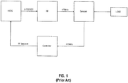
- a high voltage DC power source provides a supply voltage that is variable from 0-150VDC to an RF generator stage in accordance with an RF setpoint signal.
- the RF generator stage generates a 470kHz electrosurgical signal having an output power determined by the supply voltage.
- One or more sensors monitor the output of the RF generator as applied to a load, such as to targeted tissue of a patent. The sensors provide a feedback signal to a controller. The controller is programmed to cause the RF generator stage to generate a desired RF output signal in accordance with inputs received from a surgeon.
- the desired RF output signal may include particular power, waveform, and modulations selected to achieve a specific surgical objective such as cutting, sealing, coagulating, blending, and so forth.
- the controller processes the feedback signal in view of the desired RF output signal and turn provides the appropriate RF setpoint signal to the HVDC to achieve the desired output signal.
- This arrangement may have drawbacks, since the output of the RF stage may be non-linear with respect to the variable supply voltage input, and may also exhibit inefficiencies and instabilities at certain operating points.
- an HVDC provides a fixed DC supply voltage of to the RF generator stage.
- the RF inverter is configured to operate at this fixed supply voltage and includes an RF setpoint input.
- the RF generator stage generates an high-frequency (e.g., 470kHz) AC electrosurgical signal having an output determined by the RF setpoint input.
- Both the Fig. 1 and Fig. 2 arrangements may have drawbacks in that, as the operating point changes, either through a setpoint change or a load change, the gain exhibited by the system can vary significantly.
- Prior art solutions to the gain problem typically involve controlling a gain compensator based on known operating point data. A cross-reference of compensation factors and operating points is created by measuring the generator gain throughout an anticipated range of operating points and operation modes, which is then stored in a large three-dimensional lookup table for use during electrosurgical procedures.
- Such approaches may have drawbacks, since the lookup tables are difficult to implement, are generally device-specific, and require extensive reprogramming if even a single element of the system is changed.
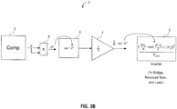
- a network model of an electrosurgical generator 1 in accordance with the present disclosure in voltage control mode and/or current control mode is shown.
- voltage control mode and current control mode the variation due to phase is caused by the sine term.
- the phase gain correction function when controlling to voltage and/or current is performed in accordance with an arcsine function.
- the generator gain is constant with respect to phase in voltage and/or current mode, as the gain would be the derivative of d, not d itself.
- a network model of an electrosurgical generator 1 in accordance with the present disclosure in power control mode is shown.
- the phase gain correction function is performed in accordance with the inverse of a sine squared function.
- a multiplier block 6 is placed which computer the square of uncorrected duty cycle d.
- the generator gain is constant with respect to phase.
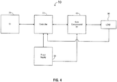
- an electrosurgical generator 10 according to the present disclosure is illustrated.
- the disclosed generator 10 compensates for the underlying cause of gain variations and precisely corrects the variation at the source.
- the described gain compensation technique is applicable any application utilizing phase shifted full bridge inverter topology. It is simpler than techniques that exist in the prior art and provides a generalized solution that will work across all circuits of this type.
- the disclosed generator 10 includes a user interface 20 that is configured to receive inputs from a user that define the operating modes and parameters of the system such as, without limitation, power level, mono- or bi-polar mode, electrosurgical energy on/off, cutting mode, sealing mode, blending mode, coagulation mode, crest factor, and so forth.
- User interface 20 may include user interface elements such as buttons, knobs, keypads, touchscreens etc. that may be disposed on a generator enclosure and/or on an electrosurgical instrument.
- User interface 20 may include visual displays and audible indicators to communicate operating status and feedback to a user.
- Electrosurgical system 10 includes a controller 30 that is in operable communication with user interface 20 and a gain-compensated radiofrequency (RF) stage 40.
- RF radiofrequency
- Controller 30 interprets operating commands received from user interface 20 and, in turn, provides one or more control signals to gain-compensated RF stage 40, such as, without limitation, a setpoint signal.
- Gain-compensated RF stage 40 may be configured to communicate one or more operating parameters to controller 30, such as, without limitation, an impedance, an output voltage, an output current, and an output power.
- Gain-compensated RF stage 40 is configured to receive a setpoint signal from controller 30 and, in response thereto, generate an electrosurgical output signal for delivery to a load 90 (e.g., to targeted tissue) in a manner described in detail below.
- Electrosurgical generator 10 includes a power supply 50 which is configured to convert line voltage (e.g., 120 VAC or 240VAC) to operating voltages required by user interface 20, controller 30, and gain-compensated RF stage 40.
- line voltage e.g., 120 VAC or 240VAC
- power supply 50 is configured to provide +5VDC, -5VDC, +12VDC, and +150VDC.
- Gain-compensated RF stage 40 employs a two-part approach to achieving gain compensation.
- the first approach addresses gain variations caused by load (impedance) variations of a full-bridge resonant inverter output stage 160.
- the second approach addresses gain variation caused by the sine term of the duty cycle modulation (e.g., pulse width modulation) of the full-bridge resonant inverter output stage 160 during current- and voltage-control modes, and gain variation caused by the sine squared term of the duty cycle modulation during power control modes.
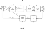
- gain-compensated RF stage 40 is generally arranged as an improved control loop having two gain-compensation error-correction elements.
- a first impedance gain compensation unit 130 is provided prior to the input of a PID section 140, and a phase gain compensation unit 150 is provided subsequent to the PID section 140.
- Gain-compensated RF stage 40 includes a summation amplifier 120 having an RF setpoint input 121 which receives RF setpoint signal 125 at a positive (+) input of summation amplifier 120.
- a calculated output signal 171 e.g., a setpoint "equivalent" corresponding to an output parameter
- Summation amplifier 120 generates a first error signal 124 at summation amplifier output 123 corresponding to the difference between the RF setpoint signal 125 (e.g., desired output) and the calculated output signal 171 (e.g., actual output).
- the first error signal 124 which is communicated as the error term to an error input 131 of impedance gain compensation unit 130.
- impedance gain compensation unit 130 includes load input 132 that is configured to receive a load signal R LOAD from full-bridge resonant inverter 160. As such, impedance gain compensation unit 130 is configured to compensate for load variations of full-bridge resonant inverter 160 in addition to gain variations.
- Impedance gain compensation unit 130 is configured to generate second error signal 134 at impedance gain compensation unit output 133 that is communicated to PID controller 140.
- the compensation required due to load variation is dependent not only on the load, but also on the control method. However, because tissue impedance changes relatively slowly in comparison to the frequency at which the setpoint may be changed, gain compensation based on load is reliably achieved.
- the load compensation is determined in accordance the gain variation equations listed in Table 1, presented below, wherein Zo0 is the Thevenin equivalent output impedance of the resonant network (e.g., reactive): TABLE 1 Voltage Current Power abs R LOAD R LOAD + Z o 0 abs 1 R LOAD + Z o 0 abs R LOAD R LOAD + Z o 0 2
- Impedance gain compensation unit 130 is programmed to receive the load as a parameter, and adds or removes gain from the system prior to processing by phase gain compensator 150 by preprocessing (e.g., pre-distorting) the error term of the inner control loop in order to compensate for the gain non-linearity due to impedance changes.
- preprocessing e.g., pre-distorting
- PID unit 140 receives error signal 134 from impedance gain compensation unit 130 and generates a phase control signal 142 which determines the duty cycle of a full-bridge inverter driver, e.g., a pulse width modulation unit, included within phase gain compensation unit 150.
- a full-bridge inverter driver e.g., a pulse width modulation unit
- phase gain compensation unit 150 receives phase control signal 142.
- the phase gain compensation unit 150 corrects for the inherent nonlinearity associated with pulse width modulation techniques.
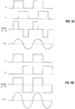
- a linear increase of the pulse width modulation duty cycle results in an increase in full-bridge inverter peak-to-peak output in accordance with the sine term.
- varying the PWM duty cycle by, e.g., varying the phase difference between the two pulse trains) from 0% to 50% results in the output of a full-bridge inverter (to vary from 0% to 70.7% of peak value.
- phase gain compensation unit 150 compensates (e.g., pre-processes or pre-distorts) phase control signal 142 by applying a compensation factor that is based at least in part upon the arcsine term to phase control signal 142, which, in turn, generates a corrected PWM driving signal 152.
- Phase control signal 142 is received by phase preprocessing module 151.
- Phase preprocessing module 151 applies the arcsine term to phase control signal 142 to generate PWM driving signal 152.
- a clock 155 provides a square wave 154 having a phase ⁇ 1 to a carrier input 155 of PWM driver 153.
- clock 155 may be integral to and/or included within PWM driver 153.
- square wave 154 has a frequency corresponding to the desired electrosurgical frequency, e.g., 470kHz.
- the corrected PWM driving signal 152 is applied to a modulation input 156 of PWM driver 153, which generates a phase-shifted, second square wave having a phase ⁇ 2.
- the phase difference between ⁇ 1 and ⁇ 2 is determined by PWM driving signal 152.
- Phase ⁇ 1 and phase ⁇ 2 are output from phase gain compensation unit 150 to drive full-bridge inverter 160.
- phase preprocessing module 151 which precisely compensates for the sine term nonlinearity of the full bridge inverter 160. In this manner, a purely linear response to the PID 140 output is achieved.
- full-bridge inverter 160 includes a plurality of transistors 162, 164, 166, 168 for configured in a full bridge arrangement to generate a pair of output pulse trains V 1 , V 2 .
- Full-bridge inverter 160 receives phase ⁇ 1 and phase ⁇ 2 outputs from phase gain compensation unit 150 for driving the plurality of transistors 162, 164, 166, 168.
- the PWM output is coupled to transistor 162, and, shifted 180 degrees by inverter 163, to transistor 164.
- ⁇ 2 is coupled to transistor 166, and to transistor 168 via inverter 167.
- This push-pull topology is used to accomplish voltage conversion from DC to RF at a desired power level determined by the phase difference between phase ⁇ 1 and phase ⁇ 2.
- the transistor pairs 162, 164 and 166, 168 conduct in accordance with their respective gate signals, at varying times, to deliver a waveform at the specified power.
- the interference between the two phase shifted, high voltage pulsetrains V 1 and V 2 generates a combined excitation voltage V EXClTE .
- V 1 and V 2 are thus summed and subsequently filtered by resonant network 165 to provide a smoothed, generally sinusoidal electrosurgical output waveform 161, 161' (V out ).
- sensor 181 are operably associated with outputs 161, 161' and/or load 190.
- sensor 181 includes a voltage sensor and/or a current sensor.
- sensor unit 180 receives sensor signals from sensor 181 from sensor 181 from sensor 181 from sensor 181 into a format suitable for use by parameter calculation unit 170.
- sensor unit 180 may include an analog to digital (A/D) converter, a buffer, an optoisolator, an amplifier, a temperature compensation device, a filter, and combinations thereof.
- A/D analog to digital
- Parameter calculation unit 170 receives the one or more sensor signals, and computes a calculated output signal 171 (i.e., a setpoint equivalent parameter) corresponding to the presently-sensed output of full-bridge inverter 160.
- the calculated output signal 171 is calculated in accordance with a current operating mode of the generator 10. For example, RMS voltage, RMS current, average power, and impedance may be calculated. If the control method of generator 10 is in a voltage-targeted mode, then the present output voltage is calculated by parameter calculation unit and subtracted from the setpoint by summation amplifier 120. If the control method of generator 10 is in a voltage-targeted mode, then the calculated output signal 171 is calculated from the present output voltage.
- the calculated output signal 171 is calculated from the present output current. Similarly, if the control method of generator 10 is in a power-targeted mode, then present output power is calculated, and if the control method of generator 10 is in an impedance-targeted mode, then the present load impedance is calculated.
- the calculated output signal 171 is received at the negative (-) input of summation amplifier 120, which sums the setpoint signal 125 with the calculated output signal 171, to generate the error signal 124 used to drive the gain-compensated RF stage 40 as just described.
Landscapes
- Health & Medical Sciences (AREA)
- Surgery (AREA)
- Life Sciences & Earth Sciences (AREA)
- Engineering & Computer Science (AREA)
- Biomedical Technology (AREA)
- Molecular Biology (AREA)
- Nuclear Medicine, Radiotherapy & Molecular Imaging (AREA)
- Veterinary Medicine (AREA)
- Physics & Mathematics (AREA)
- Heart & Thoracic Surgery (AREA)
- Medical Informatics (AREA)
- Otolaryngology (AREA)
- Animal Behavior & Ethology (AREA)
- General Health & Medical Sciences (AREA)
- Public Health (AREA)
- Plasma & Fusion (AREA)
- Surgical Instruments (AREA)
- Inverter Devices (AREA)
- Electromagnetism (AREA)
Claims (11)
- System zum Steuern eines elektrochirurgischen Generators unter Verwendung einer verstärkungskompensierten Vollbrückentopologie, umfassend:eine Summierungseinheit, die dazu konfiguriert ist, ein RF-Sollwertsignal (125) und ein berechnetes Ausgangssignal (171) zu empfangen und ein erstes Fehlersignal korrespondierend zu der Differenz zwischen dem RF-Sollwertsignal und dem berechneten Ausgangssignal zu berechnen;eine Impedanzverstärkungskompensierungseinheit, die dazu konfiguriert ist, das erste Fehlersignal (124) und ein Impedanzsignal korrespondierend zu einer Lastimpedanz zu empfangen und ein zweites Fehlersignal (134) durch Anwenden einer Impedanzkorrekturberechnung auf das erste Fehlersignal zu generieren;eine Steuerung (30), die dazu konfiguriert ist, das zweite Fehlersignal zu empfangen und ein Phasensteuerungssignal zu generieren;eine Phasenverstärkungskompensationseinheit, umfassend:ein Phasenvorverarbeitungsmodul, das dazu konfiguriert ist, das Phasensteuerungssignal zu empfangen und eine Phasenverstärkungskorrekturfunktion auf das Phasensteuerungssignal anzuwenden, um ein korrigiertes Pulsweitenmodulationsantriebssignal zu generieren; undeinen Pulsweitenmodulationstreiber, der dazu konfiguriert ist, ein erstes Vollbrückenantriebssignal und ein zweites Vollbrückenantriebssignal, das von dem ersten Vollbrückenantriebssignal um einen Betrag korrespondierend zu dem korrigierten Pulsweitenmodulationsantriebssignal phasenverschoben ist, zu generieren;einen Vollbrückenwechselrichter, der dazu konfiguriert ist, das erste Vollbrückenantriebssignal und das zweite Vollbrückenantriebssignal zu empfangen und ein elektrochirurgisches Ausgangssignal mit einer elektrischen Eigenschaft korrespondierend zu einer Phasendifferenz zwischen dem ersten Vollbrückenantriebssignal und dem zweiten Vollbrückenantriebssignal zu generieren; undeine Sensorschaltung, die dazu konfiguriert ist, eine elektrische Eigenschaft von dem elektrochirurgischen Ausgangssignal abzutasten und ein korrespondierendes berechnetes Ausgangssignal zu generieren.
- System nach Anspruch 1, wobei die Phasenverstärkungskompensationseinheit einen Zeitgeber umfasst, der dazu konfiguriert ist, das erste Vollbrückenantriebssignal zu generieren, und der in betriebsmäßiger Verbindung mit mindestens einem von dem Pulsweitenmodulationstreiber und dem Vollbrückenwechselrichter steht.
- System entweder nach Anspruch 1 oder Anspruch 2, wobei die Sensorschaltung umfasst:einen oder mehrere Sensoren, die mit einem Ausgang von dem Vollbrückenwechselrichter betriebsmäßig verbunden und dazu konfiguriert sind, ein Sensorsignal mit einem ersten Format auszugeben;eine Sensoreinheit in betriebsmäßiger Verbindung mit dem einen oder den mehreren Sensoren und konfiguriert, um das Sensorsignal zu empfangen, das Sensorsignal von dem ersten Format in ein zweites Format umzuwandeln und das Sensorsignal in dem zweiten Format auszugeben; undeine Parameterberechnungseinheit, die dazu konfiguriert ist, das Sensorsignal in dem zweiten Format zu empfangen und ein berechnetes Ausgangssignal nach einem Betriebsmodus von dem elektrochirurgischen Generator zu berechnen.
- System nach Anspruch 3, wobei der Betriebsmodus von dem elektrochirurgischen Generator (10) ausgewählt ist aus der Gruppe bestehend aus einem Spannungs-gerichteten Modus, einem Strom-gerichteten Modus, einem Leistungs-gerichteten Modus und einem Impedanz-gerichteten Modus.
- System nach einem vorstehenden Anspruch, wobei der Vollbrückenwechselrichter ein Resonanznetzwerk umfasst, das dazu konfiguriert ist, eine im Wesentlichen sinusförmige elektrochirurgische Ausgangswellenform bereitzustellen.
- System nach einem vorstehenden Anspruch, wobei die Phasenverstärkungskorrekturfunktion nach einer Arkussinusfunktion durchgeführt wird.
- System nach Anspruch 1, wobei der Vollbrückenwechselrichter ein Resonanznetzwerk umfasst und, wenn der elektrochirurgische Generator (10) in einem Spannungs-gerichteten Modus ist, die Impedanzkorrekturberechnung nach der Formel abs((RLOAD + Zo0)/RLOAD) durchgeführt wird, wobei RLOAD den detektierten Widerstand der Last bezeichnet und wobei Zo0 die äquivalente Thevenin-Ausgangsimpedanz von dem Resonanz-Netzwerk ist.
- System nach Anspruch 1, wobei der Vollbrückenwechselrichter ein Resonanz-Netzwerk umfasst und, wenn der elektrochirurgische Generator (10) in dem Strom-gerichteten Modus ist, die Impedanzkorrekturberechnung nach der Formel abs((RLOAD + Zo0)/1) durchgeführt wird, wobei RLOAD den detektierten Widerstand der Last bezeichnet und wobei Zo0 die äquivalente Thevenin-Ausgangsimpedanz von dem Resonanz-Netzwerk ist.
- System nach Anspruch 1, wobei der Vollbrückenwechselrichter ein Resonanz-Netzwerk umfasst und, wenn der elektrochirurgische Generator (10) in dem Leistungs-gerichteten Modus ist, die Impedanzkorrekturberechnung nach der Formel abs((RLOAD + Zo0)2/ RLOAD) durchgeführt wird, wobei RLOAD den detektierten Widerstand der Last bezeichnet und wobei Zo0 die äquivalente Thevenin-Ausgangsimpedanz von dem Resonanz-Netzwerk ist.
- Elektrochirurgischer Generator, umfassend:eine Steuerung, die dazu konfiguriert ist, einen Betriebsparameter von einer Benutzerschnittstelle (20) zu empfangen;eine Benutzerschnittstelle (20) in betriebsmäßiger Verbindung mit der Steuerung und konfiguriert, um eine Benutzereingabe von einem Benutzer zu empfangen; undeine Verstärkungskompensationshochfrequenzstufe,wobei die Verstärkungskompensationshochfrequenzstufe das System nach einem der Ansprüche 1 bis 9 umfasst.
- Elektrochirurgische Generator nach Anspruch 10, wenn abhängig von Anspruch 3, wobei die Phasenverstärkungskorrekturfunktion nach einer Arkussinusfunktion durchgeführt wird.
Applications Claiming Priority (2)
| Application Number | Priority Date | Filing Date | Title |
|---|---|---|---|
| US201361829433P | 2013-05-31 | 2013-05-31 | |
| US14/168,296 US9504516B2 (en) | 2013-05-31 | 2014-01-30 | Gain compensation for a full bridge inverter |
Publications (2)
| Publication Number | Publication Date |
|---|---|
| EP2807987A1 EP2807987A1 (de) | 2014-12-03 |
| EP2807987B1 true EP2807987B1 (de) | 2017-06-07 |
Family
ID=50677944
Family Applications (1)
| Application Number | Title | Priority Date | Filing Date |
|---|---|---|---|
| EP14166165.2A Active EP2807987B1 (de) | 2013-05-31 | 2014-04-28 | Verstärkungskompensation für einen Vollbrückenwechselrichter |
Country Status (5)
| Country | Link |
|---|---|
| US (2) | US9504516B2 (de) |
| EP (1) | EP2807987B1 (de) |
| CN (3) | CN104207841B (de) |
| AU (1) | AU2014201033A1 (de) |
| CA (1) | CA2849543A1 (de) |
Families Citing this family (19)
| Publication number | Priority date | Publication date | Assignee | Title |
|---|---|---|---|---|
| US9504516B2 (en) | 2013-05-31 | 2016-11-29 | Covidien LLP | Gain compensation for a full bridge inverter |
| US10130412B2 (en) | 2013-09-26 | 2018-11-20 | Covidien Lp | Systems and methods for estimating tissue parameters using surgical devices |
| US10492850B2 (en) | 2014-04-04 | 2019-12-03 | Covidien Lp | Systems and methods for calculating tissue impedance in electrosurgery |
| US10188448B2 (en) | 2014-11-21 | 2019-01-29 | Covidien Lp | Electrosurgical system for multi-frequency interrogation of parasitic parameters of an electrosurgical instrument |
| US10617463B2 (en) | 2015-04-23 | 2020-04-14 | Covidien Lp | Systems and methods for controlling power in an electrosurgical generator |
| US11090106B2 (en) * | 2015-04-23 | 2021-08-17 | Covidien Lp | Control systems for electrosurgical generator |
| US11446078B2 (en) | 2015-07-20 | 2022-09-20 | Megadyne Medical Products, Inc. | Electrosurgical wave generator |
| CN105832406B (zh) * | 2016-01-25 | 2023-10-13 | 安进医疗科技(北京)有限公司 | 功率控制方法及装置、控制设备及方法、电磁刀手术系统 |
| US10772673B2 (en) | 2016-05-02 | 2020-09-15 | Covidien Lp | Surgical energy system with universal connection features |
| US10869712B2 (en) | 2016-05-02 | 2020-12-22 | Covidien Lp | System and method for high frequency leakage reduction through selective harmonic elimination in electrosurgical generators |
| US10610287B2 (en) | 2016-05-05 | 2020-04-07 | Covidien Lp | Advanced simultaneous activation algorithm |
| US11744631B2 (en) | 2017-09-22 | 2023-09-05 | Covidien Lp | Systems and methods for controlled electrosurgical coagulation |
| US11272975B2 (en) | 2017-09-22 | 2022-03-15 | Covidien Lp | Systems and methods for controlled electrosurgical dissection |
| US11534226B2 (en) | 2017-09-22 | 2022-12-27 | Covidien Lp | Systems and methods for minimizing arcing of bipolar forceps |
| US12333423B2 (en) | 2019-02-14 | 2025-06-17 | Covidien Lp | Systems and methods for estimating tissue parameters using surgical devices |
| CN114886552B (zh) * | 2022-05-05 | 2023-07-04 | 以诺康医疗科技(苏州)有限公司 | 一种高频电刀组织闭合系统、发生器及高频电刀 |
| EP4522050A4 (de) * | 2022-05-10 | 2026-04-15 | Eximis Surgical Inc | Systeme, verfahren und vorrichtungen für einen elektrochirurgischen hf-generator zum elektrochirurgischen schneiden |
| CN114680372B (zh) * | 2022-05-26 | 2022-11-22 | 南华大学 | 气力输送控制方法、计算机可读介质、气力输送控制系统及烟丝气力输送系统 |
| CN120511957B (zh) * | 2025-05-16 | 2026-01-30 | 湖北英特利电气有限公司 | 用于二极管整流桥的纹波抑制补偿控制器及其控制方法 |
Family Cites Families (153)
| Publication number | Priority date | Publication date | Assignee | Title |
|---|---|---|---|---|
| DE179607C (de) | 1906-11-12 | |||
| DE390937C (de) | 1922-10-13 | 1924-03-03 | Adolf Erb | Vorrichtung zur Innenbeheizung von Wannenoefen zum Haerten, Anlassen, Gluehen, Vergueten und Schmelzen |
| DE1099658B (de) | 1959-04-29 | 1961-02-16 | Siemens Reiniger Werke Ag | Selbsttaetige Einschaltvorrichtung fuer Hochfrequenzchirurgiegeraete |
| FR1275415A (fr) | 1960-09-26 | 1961-11-10 | Dispositif détecteur de perturbations pour installations électriques, notamment d'électrochirurgie | |
| DE1139927B (de) | 1961-01-03 | 1962-11-22 | Friedrich Laber | Hochfrequenz-Chirurgiegeraet |
| DE1149832C2 (de) | 1961-02-25 | 1977-10-13 | Siemens AG, 1000 Berlin und 8000 München | Hochfrequenz-chirurgieapparat |
| FR1347865A (fr) | 1962-11-22 | 1964-01-04 | Perfectionnements aux appareils de diathermo-coagulation | |
| DE1439302B2 (de) | 1963-10-26 | 1971-05-19 | Siemens AG, 1000 Berlin u 8000 München | Hochfrequenz Chirurgiegerat |
| US3601126A (en) | 1969-01-08 | 1971-08-24 | Electro Medical Systems Inc | High frequency electrosurgical apparatus |
| US3826263A (en) | 1970-08-13 | 1974-07-30 | R Shaw | Electrically heated surgical cutting instrument |
| US3683923A (en) | 1970-09-25 | 1972-08-15 | Valleylab Inc | Electrosurgery safety circuit |
| US3887861A (en) * | 1972-09-14 | 1975-06-03 | Tokyo Keiki Kk | Transistor inverter |
| GB1480736A (en) | 1973-08-23 | 1977-07-20 | Matburn Ltd | Electrodiathermy apparatus |
| DE2455174A1 (de) | 1973-11-21 | 1975-05-22 | Termiflex Corp | Ein/ausgabegeraet zum datenaustausch mit datenverarbeitungseinrichtungen |
| DE2407559C3 (de) | 1974-02-16 | 1982-01-21 | Dornier System Gmbh, 7990 Friedrichshafen | Wärmesonde |
| JPS5710740B2 (de) | 1974-06-17 | 1982-02-27 | ||
| US3964487A (en) | 1974-12-09 | 1976-06-22 | The Birtcher Corporation | Uncomplicated load-adapting electrosurgical cutting generator |
| US4237887A (en) | 1975-01-23 | 1980-12-09 | Valleylab, Inc. | Electrosurgical device |
| DE2504280C3 (de) | 1975-02-01 | 1980-08-28 | Hans Heinrich Prof. Dr. 8035 Gauting Meinke | Vorrichtung zum Schneiden und/oder Koagulieren menschlichen Gewebes mit Hochfrequenzstrom |
| US3978393A (en) | 1975-04-21 | 1976-08-31 | Burroughs Corporation | High efficiency switching regulator |
| CA1064581A (en) | 1975-06-02 | 1979-10-16 | Stephen W. Andrews | Pulse control circuit and method for electrosurgical units |
| DE2540968C2 (de) | 1975-09-13 | 1982-12-30 | Erbe Elektromedizin GmbH, 7400 Tübingen | Einrichtung zum Einschalten des Koagulationsstroms einer bipolaren Koagulationspinzette |
| US4092986A (en) | 1976-06-14 | 1978-06-06 | Ipco Hospital Supply Corporation (Whaledent International Division) | Constant output electrosurgical unit |
| US4094320A (en) | 1976-09-09 | 1978-06-13 | Valleylab, Inc. | Electrosurgical safety circuit and method of using same |
| US4126137A (en) | 1977-01-21 | 1978-11-21 | Minnesota Mining And Manufacturing Company | Electrosurgical unit |
| FR2390968A1 (fr) | 1977-05-16 | 1978-12-15 | Skovajsa Joseph | Dispositif de traitement local d'un patient, notamment pour acupuncture ou auriculotherapie |
| FR2391588A1 (fr) | 1977-05-18 | 1978-12-15 | Satelec Soc | Generateur de tension haute frequence |
| SU727201A2 (ru) | 1977-11-02 | 1980-04-15 | Киевский Научно-Исследовательский Институт Нейрохирургии | Электрохирургический аппарат |
| US4188927A (en) | 1978-01-12 | 1980-02-19 | Valleylab, Inc. | Multiple source electrosurgical generator |
| DE2803275C3 (de) | 1978-01-26 | 1980-09-25 | Aesculap-Werke Ag Vormals Jetter & Scheerer, 7200 Tuttlingen | Fernschalteinrichtung zum Schalten eines monopolaren HF-Chirurgiegerätes |
| DE2823291A1 (de) | 1978-05-27 | 1979-11-29 | Rainer Ing Grad Koch | Schaltung zur automatischen einschaltung des hochfrequenzstromes von hochfrequenz-koagulationsgeraeten |
| DE2946728A1 (de) | 1979-11-20 | 1981-05-27 | Erbe Elektromedizin GmbH & Co KG, 7400 Tübingen | Hochfrequenz-chirurgiegeraet |
| US4287557A (en) | 1979-12-17 | 1981-09-01 | General Electric Company | Inverter with improved regulation |
| JPS5778844A (en) | 1980-11-04 | 1982-05-17 | Kogyo Gijutsuin | Lasre knife |
| DE3045996A1 (de) | 1980-12-05 | 1982-07-08 | Medic Eschmann Handelsgesellschaft für medizinische Instrumente mbH, 2000 Hamburg | Elektro-chirurgiegeraet |
| FR2502935B1 (fr) | 1981-03-31 | 1985-10-04 | Dolley Roger | Procede et dispositif de controle de la coagulation de tissus a l'aide d'un courant a haute frequence |
| DE3120102A1 (de) | 1981-05-20 | 1982-12-09 | F.L. Fischer GmbH & Co, 7800 Freiburg | Anordnung zur hochfrequenzkoagulation von eiweiss fuer chirurgische zwecke |
| DE3269219D1 (en) | 1981-11-17 | 1986-03-27 | Fisons Plc | Dihydropyridines, methods for their production and their formulation and use as pharmaceuticals |
| FR2517953A1 (fr) | 1981-12-10 | 1983-06-17 | Alvar Electronic | Appareil diaphanometre et son procede d'utilisation |
| US4524444A (en) | 1982-01-12 | 1985-06-18 | Discovision Associates | Analyzing the signal transfer characteristics of a signal processing unit |
| US4590934A (en) | 1983-05-18 | 1986-05-27 | Jerry L. Malis | Bipolar cutter/coagulator |
| JPS603889A (ja) | 1983-06-20 | 1985-01-10 | 松下電器産業株式会社 | 誘導加熱調理器 |
| US4658819A (en) | 1983-09-13 | 1987-04-21 | Valleylab, Inc. | Electrosurgical generator |
| US4586120A (en) | 1983-12-30 | 1986-04-29 | At&T Bell Laboratories | Current limit shutdown circuit with time delay |
| US4727874A (en) | 1984-09-10 | 1988-03-01 | C. R. Bard, Inc. | Electrosurgical generator with high-frequency pulse width modulated feedback power control |
| FR2573301B3 (fr) | 1984-11-16 | 1987-04-30 | Lamidey Gilles | Pince chirurgicale et son appareillage de commande et de controle |
| DE3510586A1 (de) | 1985-03-23 | 1986-10-02 | Erbe Elektromedizin GmbH, 7400 Tübingen | Kontrolleinrichtung fuer ein hochfrequenz-chirurgiegeraet |
| US4887199A (en) | 1986-02-07 | 1989-12-12 | Astec International Limited | Start circuit for generation of pulse width modulated switching pulses for switch mode power supplies |
| DE3604823C2 (de) | 1986-02-15 | 1995-06-01 | Lindenmeier Heinz | Hochfrequenzgenerator mit automatischer Leistungsregelung für die Hochfrequenzchirurgie |
| EP0246350A1 (de) | 1986-05-23 | 1987-11-25 | Erbe Elektromedizin GmbH. | Koagulationselektrode |
| JPS635876A (ja) | 1986-06-27 | 1988-01-11 | Hitachi Seiko Ltd | ア−ク溶接機 |
| DE3638748A1 (de) | 1986-11-13 | 1988-06-01 | Hirschmann Radiotechnik | Kapazitives trennglied |
| US5073167A (en) | 1987-06-26 | 1991-12-17 | M/A-Com, Inc. | In-line microwave warming apparatus |
| US4931047A (en) | 1987-09-30 | 1990-06-05 | Cavitron, Inc. | Method and apparatus for providing enhanced tissue fragmentation and/or hemostasis |
| EP0325456B1 (de) | 1988-01-20 | 1995-12-27 | G2 Design Limited | Diathermiegerät |
| GB8801177D0 (en) | 1988-01-20 | 1988-02-17 | Goble N M | Diathermy unit |
| EP0336742A3 (de) | 1988-04-08 | 1990-05-16 | Bristol-Myers Company | Methode und Gerät zur Eichung eines elektrochirugischen Gerätes |
| US4961047A (en) | 1988-11-10 | 1990-10-02 | Smiths Industries Public Limited Company | Electrical power control apparatus and methods |
| DE3904558C2 (de) | 1989-02-15 | 1997-09-18 | Lindenmeier Heinz | Automatisch leistungsgeregelter Hochfrequenzgenerator für die Hochfrequenz-Chirurgie |
| DE58908600D1 (de) | 1989-04-01 | 1994-12-08 | Erbe Elektromedizin | Einrichtung zur Überwachung der Applikation von Neutralelektroden bei der Hochfrequenzchirurgie. |
| US5531774A (en) | 1989-09-22 | 1996-07-02 | Alfred E. Mann Foundation For Scientific Research | Multichannel implantable cochlear stimulator having programmable bipolar, monopolar or multipolar electrode configurations |
| US5113116A (en) | 1989-10-05 | 1992-05-12 | Firma J. Eberspacher | Circuit arrangement for accurately and effectively driving an ultrasonic transducer |
| DE3942998C2 (de) | 1989-12-27 | 1998-11-26 | Delma Elektro Med App | Elektrochirurgisches Hochfrequenzgerät |
| US5906614A (en) | 1991-11-08 | 1999-05-25 | Ep Technologies, Inc. | Tissue heating and ablation systems and methods using predicted temperature for monitoring and control |
| US5498261A (en) | 1991-12-20 | 1996-03-12 | Advanced Cardiovascular Systems, Inc. | Thermal angioplasty system |
| DE4205213A1 (de) | 1992-02-20 | 1993-08-26 | Delma Elektro Med App | Hochfrequenzchirurgiegeraet |
| DE4206433A1 (de) | 1992-02-29 | 1993-09-02 | Bosch Gmbh Robert | Kapazitives trennstueck |
| US5414238A (en) | 1992-10-02 | 1995-05-09 | Martin Marietta Corporation | Resonant power supply for an arcjet thruster |
| US5348554A (en) | 1992-12-01 | 1994-09-20 | Cardiac Pathways Corporation | Catheter for RF ablation with cooled electrode |
| CA2096559C (en) | 1993-05-19 | 1999-03-02 | Daniel Pringle | Resonant unity power factor converter |
| US5678568A (en) | 1993-07-27 | 1997-10-21 | Olympus Optical Co., Ltd. | System control apparatus, medical system control apparatus and image-plane display method of medical system control apparatus |
| DE4339049C2 (de) | 1993-11-16 | 2001-06-28 | Erbe Elektromedizin | Einrichtung zur Konfiguration chirurgischer Systeme |
| US5396194A (en) | 1993-11-19 | 1995-03-07 | Carver Corporation | Audio frequency power amplifiers |
| WO1996000528A1 (en) | 1994-06-27 | 1996-01-11 | Ep Technologies, Inc. | Non-linear control systems and methods for heating and ablating body tissue |
| US6409722B1 (en) | 1998-07-07 | 2002-06-25 | Medtronic, Inc. | Apparatus and method for creating, maintaining, and controlling a virtual electrode used for the ablation of tissue |
| DE19506363A1 (de) | 1995-02-24 | 1996-08-29 | Frost Lore Geb Haupt | Verfahren zur nicht-invasiven Thermometrie in Organen unter medizinischen Hyperthermie- und Koagulationsbedingungen |
| US5837001A (en) | 1995-12-08 | 1998-11-17 | C. R. Bard | Radio frequency energy delivery system for multipolar electrode catheters |
| DE19643127A1 (de) | 1996-10-18 | 1998-04-23 | Berchtold Gmbh & Co Geb | Hochfrequenzchirurgiegerät und Verfahren zu dessen Betrieb |
| US5729448A (en) | 1996-10-31 | 1998-03-17 | Hewlett-Packard Company | Low cost highly manufacturable DC-to-DC power converter |
| US7269034B2 (en) | 1997-01-24 | 2007-09-11 | Synqor, Inc. | High efficiency power converter |
| DE19717411A1 (de) | 1997-04-25 | 1998-11-05 | Aesculap Ag & Co Kg | Verfahren und Vorrichtung zur Überwachung der thermischen Belastung des Gewebes eines Patienten |
| US5838558A (en) | 1997-05-19 | 1998-11-17 | Trw Inc. | Phase staggered full-bridge converter with soft-PWM switching |
| EP0882955B1 (de) | 1997-06-06 | 2005-04-06 | Endress + Hauser GmbH + Co. KG | Mit Mikrowellen arbeitendes Füllstandsmessgerät |
| US6974463B2 (en) | 1999-02-09 | 2005-12-13 | Innercool Therapies, Inc. | System and method for patient temperature control employing temperature projection algorithm |
| US6537272B2 (en) | 1998-07-07 | 2003-03-25 | Medtronic, Inc. | Apparatus and method for creating, maintaining, and controlling a virtual electrode used for the ablation of tissue |
| US6123702A (en) | 1998-09-10 | 2000-09-26 | Scimed Life Systems, Inc. | Systems and methods for controlling power in an electrosurgical probe |
| US6245065B1 (en) | 1998-09-10 | 2001-06-12 | Scimed Life Systems, Inc. | Systems and methods for controlling power in an electrosurgical probe |
| US6183468B1 (en) | 1998-09-10 | 2001-02-06 | Scimed Life Systems, Inc. | Systems and methods for controlling power in an electrosurgical probe |
| DE19848540A1 (de) | 1998-10-21 | 2000-05-25 | Reinhard Kalfhaus | Schaltungsanordnung und Verfahren zum Betreiben eines Wechselrichters |
| US7364577B2 (en) | 2002-02-11 | 2008-04-29 | Sherwood Services Ag | Vessel sealing system |
| EP0999514B1 (de) | 1998-11-02 | 2006-06-14 | Datalogic S.P.A. | Anordnung zur automatischen Erfassung und Verarbeitung von optischen Codes |
| US6939346B2 (en) | 1999-04-21 | 2005-09-06 | Oratec Interventions, Inc. | Method and apparatus for controlling a temperature-controlled probe |
| US6162217A (en) | 1999-04-21 | 2000-12-19 | Oratec Interventions, Inc. | Method and apparatus for controlling a temperature-controlled probe |
| US6203541B1 (en) | 1999-04-23 | 2001-03-20 | Sherwood Services Ag | Automatic activation of electrosurgical generator bipolar output |
| US6696844B2 (en) | 1999-06-04 | 2004-02-24 | Engineering & Research Associates, Inc. | Apparatus and method for real time determination of materials' electrical properties |
| WO2001017453A2 (en) | 1999-09-08 | 2001-03-15 | Curon Medical, Inc. | Systems and methods for monitoring and controlling use of medical devices |
| US6442434B1 (en) | 1999-10-19 | 2002-08-27 | Abiomed, Inc. | Methods and apparatus for providing a sufficiently stable power to a load in an energy transfer system |
| JP4667709B2 (ja) | 2000-08-08 | 2011-04-13 | エルベ エレクトロメディツィン ゲーエムベーハー | 許容電力量を調整できる高周波外科手術用高周波発生器および許容電力の制御方法 |
| JP4499893B2 (ja) | 2000-08-23 | 2010-07-07 | オリンパス株式会社 | 電気手術装置 |
| US6693782B1 (en) | 2000-09-20 | 2004-02-17 | Dell Products L.P. | Surge suppression for current limiting circuits |
| ES2255514T3 (es) | 2000-10-17 | 2006-07-01 | Asthmatx, Inc. | Modificacion de las vias respiratorias mediante la aplicacion de energia. |
| US6740085B2 (en) | 2000-11-16 | 2004-05-25 | Olympus Corporation | Heating treatment system |
| DE10061278B4 (de) | 2000-12-08 | 2004-09-16 | GFD-Gesellschaft für Diamantprodukte mbH | Instrument für chirurgische Zwecke |
| FR2825552B1 (fr) | 2001-05-30 | 2004-07-09 | Mitsubishi Electric Inf Tech | Dispositif et procede de demodulation numerique d'un signal recu par selection d'un filtre et recepteur de communication numerique le comportant |
| US6740079B1 (en) | 2001-07-12 | 2004-05-25 | Neothermia Corporation | Electrosurgical generator |
| US7294127B2 (en) | 2002-03-05 | 2007-11-13 | Baylis Medical Company Inc. | Electrosurgical tissue treatment method |
| DE10218894A1 (de) | 2002-04-26 | 2003-11-13 | Storz Endoskop Prod Gmbh | Vorrichtung zur Überwachung medizinischer Geräte |
| DE10218895B4 (de) | 2002-04-26 | 2006-12-21 | Storz Endoskop Produktions Gmbh | Hochfrequenz-Chirurgiegenerator |
| US7041096B2 (en) | 2002-10-24 | 2006-05-09 | Synergetics Usa, Inc. | Electrosurgical generator apparatus |
| US7190933B2 (en) | 2002-11-01 | 2007-03-13 | Intergration Associates Inc. | Method and apparatus for automatic tuning of a resonant loop antenna in a transceiver circuit |
| US7058372B1 (en) | 2002-11-01 | 2006-06-06 | Integration Associates Inc. | Method and apparatus for automatic tuning of a resonant loop antenna |
| US6942660B2 (en) | 2002-11-19 | 2005-09-13 | Conmed Corporation | Electrosurgical generator and method with multiple semi-autonomously executable functions |
| WO2004098385A2 (en) | 2003-05-01 | 2004-11-18 | Sherwood Services Ag | Method and system for programing and controlling an electrosurgical generator system |
| US7396336B2 (en) | 2003-10-30 | 2008-07-08 | Sherwood Services Ag | Switched resonant ultrasonic power amplifier system |
| JP2005185657A (ja) | 2003-12-26 | 2005-07-14 | Olympus Corp | 外科用処置具 |
| JP4597626B2 (ja) * | 2004-03-01 | 2010-12-15 | 株式会社ダイヘン | アーク加工用電源装置及びインバータ電源装置 |
| US7250746B2 (en) | 2004-03-31 | 2007-07-31 | Matsushita Electric Industrial Co., Ltd. | Current mode switching regulator with predetermined on time |
| CN2777841Y (zh) * | 2004-10-27 | 2006-05-03 | 华为技术有限公司 | 全桥脉宽调制移相控制器 |
| DE102004054575A1 (de) | 2004-11-11 | 2006-05-24 | Erbe Elektromedizin Gmbh | Regelung für ein HF-Chirurgiegerät |
| US20060161148A1 (en) * | 2005-01-13 | 2006-07-20 | Robert Behnke | Circuit and method for controlling an electrosurgical generator using a full bridge topology |
| US20060224151A1 (en) | 2005-03-31 | 2006-10-05 | Sherwood Services Ag | System and method for projecting a virtual user interface for controlling electrosurgical generator |
| US7655003B2 (en) | 2005-06-22 | 2010-02-02 | Smith & Nephew, Inc. | Electrosurgical power control |
| US8734438B2 (en) | 2005-10-21 | 2014-05-27 | Covidien Ag | Circuit and method for reducing stored energy in an electrosurgical generator |
| US7651492B2 (en) | 2006-04-24 | 2010-01-26 | Covidien Ag | Arc based adaptive control system for an electrosurgical unit |
| US7799020B2 (en) | 2006-10-02 | 2010-09-21 | Conmed Corporation | Near-instantaneous responsive closed loop control electrosurgical generator and method |
| US7736358B2 (en) | 2006-10-02 | 2010-06-15 | Conmed Corporation | Electrosurgical generator and method for simulating output signals |
| CN102961184B (zh) | 2006-10-10 | 2016-08-10 | 医疗设备创新有限公司 | 利用微波辐射来治疗组织的装置以及天线校准系统和方法 |
| WO2008053532A1 (en) | 2006-10-31 | 2008-05-08 | Olympus Medical Systems Corp. | High frequency cautery electric power source device |
| GB0624658D0 (en) | 2006-12-11 | 2007-01-17 | Medical Device Innovations Ltd | Electrosurgical ablation apparatus and a method of ablating biological tissue |
| USD574323S1 (en) | 2007-02-12 | 2008-08-05 | Tyco Healthcare Group Lp | Generator |
| GB0704650D0 (en) | 2007-03-09 | 2007-04-18 | Medical Device Innovations Ltd | Tissue classifying apparatus |
| US7863841B2 (en) | 2007-06-15 | 2011-01-04 | Paolo Menegoli | Class H drive |
| AU2008279121B2 (en) | 2007-07-24 | 2013-09-19 | Boston Scientific Scimed, Inc. | System and method for controlling power based on impedance detection, such as controlling power to tissue treatment devices |
| TWI355498B (en) | 2007-11-19 | 2012-01-01 | Inventec Corp | Power measuring apparatus |
| AU2008335715B2 (en) | 2007-12-12 | 2014-01-23 | Miradry, Inc. | Systems, apparatus, methods and procedures for the noninvasive treatment of tissue using microwave energy |
| US8045943B2 (en) | 2008-01-29 | 2011-10-25 | Freescale Semiconductor, Inc. | High performance CMOS radio frequency receiver |
| GB0807625D0 (en) | 2008-04-25 | 2008-06-04 | Glonav Ltd | Method and system for detecting timing characteristics in a communications system |
| US8287529B2 (en) | 2008-09-05 | 2012-10-16 | Tyco Healthcare Group Lp | Electrosurgical apparatus with high speed energy recovery |
| US8377053B2 (en) | 2008-09-05 | 2013-02-19 | Covidien Lp | Electrosurgical apparatus with high speed energy recovery |
| DE102008058737B4 (de) | 2008-09-08 | 2019-12-12 | Erbe Elektromedizin Gmbh | HF-Chirurgiegenerator |
| US9039695B2 (en) | 2009-10-09 | 2015-05-26 | Ethicon Endo-Surgery, Inc. | Surgical generator for ultrasonic and electrosurgical devices |
| US8610501B2 (en) | 2009-11-16 | 2013-12-17 | Covidien Lp | Class resonant-H electrosurgical generators |
| US8655299B2 (en) | 2010-06-03 | 2014-02-18 | Broadcom Corporation | Saw-less receiver with RF frequency translated BPF |
| US8617154B2 (en) | 2010-06-25 | 2013-12-31 | Covidien Lp | Current-fed push-pull converter with passive voltage clamp |
| US9375247B2 (en) | 2011-03-16 | 2016-06-28 | Covidien Lp | System and method for electrosurgical generator power measurement |
| US8968293B2 (en) | 2011-04-12 | 2015-03-03 | Covidien Lp | Systems and methods for calibrating power measurements in an electrosurgical generator |
| US9028479B2 (en) | 2011-08-01 | 2015-05-12 | Covidien Lp | Electrosurgical apparatus with real-time RF tissue energy control |
| CN102307020B (zh) * | 2011-09-05 | 2013-10-30 | 华南理工大学 | 一种移相软开关高频隔离型光伏并网逆变器 |
| US9099863B2 (en) | 2011-09-09 | 2015-08-04 | Covidien Lp | Surgical generator and related method for mitigating overcurrent conditions |
| US10376301B2 (en) | 2011-09-28 | 2019-08-13 | Covidien Lp | Logarithmic amplifier, electrosurgical generator including same, and method of controlling electrosurgical generator using same |
| US9192424B2 (en) | 2012-05-31 | 2015-11-24 | Covidien Lp | AC active load |
| US9861425B2 (en) | 2012-10-02 | 2018-01-09 | Covidien Lp | System and method for using resonance phasing for measuring impedance |
| US9504516B2 (en) | 2013-05-31 | 2016-11-29 | Covidien LLP | Gain compensation for a full bridge inverter |
-
2014
- 2014-01-30 US US14/168,296 patent/US9504516B2/en active Active
- 2014-02-27 AU AU2014201033A patent/AU2014201033A1/en not_active Abandoned
- 2014-04-09 CN CN201410138870.5A patent/CN104207841B/zh not_active Expired - Fee Related
- 2014-04-09 CN CN201420173413.5U patent/CN204219029U/zh not_active Expired - Fee Related
- 2014-04-09 CN CN201520109639.3U patent/CN204744401U/zh not_active Expired - Fee Related
- 2014-04-22 CA CA2849543A patent/CA2849543A1/en not_active Abandoned
- 2014-04-28 EP EP14166165.2A patent/EP2807987B1/de active Active
-
2016
- 2016-11-11 US US15/349,646 patent/US10603098B2/en active Active
Also Published As
| Publication number | Publication date |
|---|---|
| CN204744401U (zh) | 2015-11-11 |
| CN204219029U (zh) | 2015-03-25 |
| CN104207841B (zh) | 2018-02-27 |
| EP2807987A1 (de) | 2014-12-03 |
| US9504516B2 (en) | 2016-11-29 |
| US20170056092A1 (en) | 2017-03-02 |
| CA2849543A1 (en) | 2014-11-30 |
| CN104207841A (zh) | 2014-12-17 |
| US10603098B2 (en) | 2020-03-31 |
| US20140358138A1 (en) | 2014-12-04 |
| AU2014201033A1 (en) | 2014-12-18 |
Similar Documents
| Publication | Publication Date | Title |
|---|---|---|
| EP2807987B1 (de) | Verstärkungskompensation für einen Vollbrückenwechselrichter | |
| US11864814B2 (en) | System and method for harmonic control of dual-output generators | |
| US11969201B2 (en) | Control systems for electrosurgical generator | |
| US10993761B2 (en) | Electrosurgical apparatus with real-time RF tissue energy control | |
| US6193713B1 (en) | Method for the operation of a high frequency ablation apparatus and apparatus for the high frequency tissue ablation | |
| EP2322108B1 (de) | Elektrochirurgische Generatoren der H-Resonanzklasse | |
| US9770283B2 (en) | Systems and methods for improving efficiency of electrosurgical generators | |
| US10869712B2 (en) | System and method for high frequency leakage reduction through selective harmonic elimination in electrosurgical generators | |
| US9839469B2 (en) | Systems and methods for improving efficiency of electrosurgical generators | |
| AU2014218371B2 (en) | Systems and methods for improving efficiency of electrosurgical generators |
Legal Events
| Date | Code | Title | Description |
|---|---|---|---|
| PUAI | Public reference made under article 153(3) epc to a published international application that has entered the european phase |
Free format text: ORIGINAL CODE: 0009012 |
|
| 17P | Request for examination filed |
Effective date: 20140428 |
|
| AK | Designated contracting states |
Kind code of ref document: A1 Designated state(s): AL AT BE BG CH CY CZ DE DK EE ES FI FR GB GR HR HU IE IS IT LI LT LU LV MC MK MT NL NO PL PT RO RS SE SI SK SM TR |
|
| AX | Request for extension of the european patent |
Extension state: BA ME |
|
| R17P | Request for examination filed (corrected) |
Effective date: 20150522 |
|
| RBV | Designated contracting states (corrected) |
Designated state(s): AL AT BE BG CH CY CZ DE DK EE ES FI FR GB GR HR HU IE IS IT LI LT LU LV MC MK MT NL NO PL PT RO RS SE SI SK SM TR |
|
| 17Q | First examination report despatched |
Effective date: 20160421 |
|
| GRAP | Despatch of communication of intention to grant a patent |
Free format text: ORIGINAL CODE: EPIDOSNIGR1 |
|
| INTG | Intention to grant announced |
Effective date: 20161215 |
|
| RIN1 | Information on inventor provided before grant (corrected) |
Inventor name: MATTMILLER, AARON Inventor name: WASKIEWICZ, ALEXANDER M. Inventor name: TONN, DONALD |
|
| GRAS | Grant fee paid |
Free format text: ORIGINAL CODE: EPIDOSNIGR3 |
|
| AK | Designated contracting states |
Kind code of ref document: B1 Designated state(s): AL AT BE BG CH CY CZ DE DK EE ES FI FR GB GR HR HU IE IS IT LI LT LU LV MC MK MT NL NO PL PT RO RS SE SI SK SM TR |
|
| REG | Reference to a national code |
Ref country code: GB Ref legal event code: FG4D |
|
| GRAA | (expected) grant |
Free format text: ORIGINAL CODE: 0009210 |
|
| REG | Reference to a national code |
Ref country code: CH Ref legal event code: EP Ref country code: AT Ref legal event code: REF Ref document number: 898630 Country of ref document: AT Kind code of ref document: T Effective date: 20170615 |
|
| REG | Reference to a national code |
Ref country code: IE Ref legal event code: FG4D |
|
| REG | Reference to a national code |
Ref country code: DE Ref legal event code: R096 Ref document number: 602014010440 Country of ref document: DE |
|
| REG | Reference to a national code |
Ref country code: NL Ref legal event code: MP Effective date: 20170607 |
|
| REG | Reference to a national code |
Ref country code: LT Ref legal event code: MG4D |
|
| PG25 | Lapsed in a contracting state [announced via postgrant information from national office to epo] |
Ref country code: FI Free format text: LAPSE BECAUSE OF FAILURE TO SUBMIT A TRANSLATION OF THE DESCRIPTION OR TO PAY THE FEE WITHIN THE PRESCRIBED TIME-LIMIT Effective date: 20170607 Ref country code: GR Free format text: LAPSE BECAUSE OF FAILURE TO SUBMIT A TRANSLATION OF THE DESCRIPTION OR TO PAY THE FEE WITHIN THE PRESCRIBED TIME-LIMIT Effective date: 20170908 Ref country code: NO Free format text: LAPSE BECAUSE OF FAILURE TO SUBMIT A TRANSLATION OF THE DESCRIPTION OR TO PAY THE FEE WITHIN THE PRESCRIBED TIME-LIMIT Effective date: 20170907 Ref country code: HR Free format text: LAPSE BECAUSE OF FAILURE TO SUBMIT A TRANSLATION OF THE DESCRIPTION OR TO PAY THE FEE WITHIN THE PRESCRIBED TIME-LIMIT Effective date: 20170607 Ref country code: LT Free format text: LAPSE BECAUSE OF FAILURE TO SUBMIT A TRANSLATION OF THE DESCRIPTION OR TO PAY THE FEE WITHIN THE PRESCRIBED TIME-LIMIT Effective date: 20170607 Ref country code: ES Free format text: LAPSE BECAUSE OF FAILURE TO SUBMIT A TRANSLATION OF THE DESCRIPTION OR TO PAY THE FEE WITHIN THE PRESCRIBED TIME-LIMIT Effective date: 20170607 |
|
| REG | Reference to a national code |
Ref country code: AT Ref legal event code: MK05 Ref document number: 898630 Country of ref document: AT Kind code of ref document: T Effective date: 20170607 |
|
| PG25 | Lapsed in a contracting state [announced via postgrant information from national office to epo] |
Ref country code: BG Free format text: LAPSE BECAUSE OF FAILURE TO SUBMIT A TRANSLATION OF THE DESCRIPTION OR TO PAY THE FEE WITHIN THE PRESCRIBED TIME-LIMIT Effective date: 20170907 Ref country code: RS Free format text: LAPSE BECAUSE OF FAILURE TO SUBMIT A TRANSLATION OF THE DESCRIPTION OR TO PAY THE FEE WITHIN THE PRESCRIBED TIME-LIMIT Effective date: 20170607 Ref country code: NL Free format text: LAPSE BECAUSE OF FAILURE TO SUBMIT A TRANSLATION OF THE DESCRIPTION OR TO PAY THE FEE WITHIN THE PRESCRIBED TIME-LIMIT Effective date: 20170607 Ref country code: LV Free format text: LAPSE BECAUSE OF FAILURE TO SUBMIT A TRANSLATION OF THE DESCRIPTION OR TO PAY THE FEE WITHIN THE PRESCRIBED TIME-LIMIT Effective date: 20170607 Ref country code: SE Free format text: LAPSE BECAUSE OF FAILURE TO SUBMIT A TRANSLATION OF THE DESCRIPTION OR TO PAY THE FEE WITHIN THE PRESCRIBED TIME-LIMIT Effective date: 20170607 |
|
| PG25 | Lapsed in a contracting state [announced via postgrant information from national office to epo] |
Ref country code: AT Free format text: LAPSE BECAUSE OF FAILURE TO SUBMIT A TRANSLATION OF THE DESCRIPTION OR TO PAY THE FEE WITHIN THE PRESCRIBED TIME-LIMIT Effective date: 20170607 Ref country code: SK Free format text: LAPSE BECAUSE OF FAILURE TO SUBMIT A TRANSLATION OF THE DESCRIPTION OR TO PAY THE FEE WITHIN THE PRESCRIBED TIME-LIMIT Effective date: 20170607 Ref country code: EE Free format text: LAPSE BECAUSE OF FAILURE TO SUBMIT A TRANSLATION OF THE DESCRIPTION OR TO PAY THE FEE WITHIN THE PRESCRIBED TIME-LIMIT Effective date: 20170607 Ref country code: RO Free format text: LAPSE BECAUSE OF FAILURE TO SUBMIT A TRANSLATION OF THE DESCRIPTION OR TO PAY THE FEE WITHIN THE PRESCRIBED TIME-LIMIT Effective date: 20170607 Ref country code: CZ Free format text: LAPSE BECAUSE OF FAILURE TO SUBMIT A TRANSLATION OF THE DESCRIPTION OR TO PAY THE FEE WITHIN THE PRESCRIBED TIME-LIMIT Effective date: 20170607 |
|
| PG25 | Lapsed in a contracting state [announced via postgrant information from national office to epo] |
Ref country code: IS Free format text: LAPSE BECAUSE OF FAILURE TO SUBMIT A TRANSLATION OF THE DESCRIPTION OR TO PAY THE FEE WITHIN THE PRESCRIBED TIME-LIMIT Effective date: 20171007 Ref country code: IT Free format text: LAPSE BECAUSE OF FAILURE TO SUBMIT A TRANSLATION OF THE DESCRIPTION OR TO PAY THE FEE WITHIN THE PRESCRIBED TIME-LIMIT Effective date: 20170607 Ref country code: PL Free format text: LAPSE BECAUSE OF FAILURE TO SUBMIT A TRANSLATION OF THE DESCRIPTION OR TO PAY THE FEE WITHIN THE PRESCRIBED TIME-LIMIT Effective date: 20170607 Ref country code: SM Free format text: LAPSE BECAUSE OF FAILURE TO SUBMIT A TRANSLATION OF THE DESCRIPTION OR TO PAY THE FEE WITHIN THE PRESCRIBED TIME-LIMIT Effective date: 20170607 |
|
| REG | Reference to a national code |
Ref country code: DE Ref legal event code: R097 Ref document number: 602014010440 Country of ref document: DE |
|
| PLBE | No opposition filed within time limit |
Free format text: ORIGINAL CODE: 0009261 |
|
| STAA | Information on the status of an ep patent application or granted ep patent |
Free format text: STATUS: NO OPPOSITION FILED WITHIN TIME LIMIT |
|
| PG25 | Lapsed in a contracting state [announced via postgrant information from national office to epo] |
Ref country code: DK Free format text: LAPSE BECAUSE OF FAILURE TO SUBMIT A TRANSLATION OF THE DESCRIPTION OR TO PAY THE FEE WITHIN THE PRESCRIBED TIME-LIMIT Effective date: 20170607 |
|
| 26N | No opposition filed |
Effective date: 20180308 |
|
| PG25 | Lapsed in a contracting state [announced via postgrant information from national office to epo] |
Ref country code: SI Free format text: LAPSE BECAUSE OF FAILURE TO SUBMIT A TRANSLATION OF THE DESCRIPTION OR TO PAY THE FEE WITHIN THE PRESCRIBED TIME-LIMIT Effective date: 20170607 |
|
| PG25 | Lapsed in a contracting state [announced via postgrant information from national office to epo] |
Ref country code: MC Free format text: LAPSE BECAUSE OF FAILURE TO SUBMIT A TRANSLATION OF THE DESCRIPTION OR TO PAY THE FEE WITHIN THE PRESCRIBED TIME-LIMIT Effective date: 20170607 |
|
| REG | Reference to a national code |
Ref country code: CH Ref legal event code: PL |
|
| REG | Reference to a national code |
Ref country code: BE Ref legal event code: MM Effective date: 20180430 |
|
| GBPC | Gb: european patent ceased through non-payment of renewal fee |
Effective date: 20180428 |
|
| REG | Reference to a national code |
Ref country code: IE Ref legal event code: MM4A |
|
| PG25 | Lapsed in a contracting state [announced via postgrant information from national office to epo] |
Ref country code: LU Free format text: LAPSE BECAUSE OF NON-PAYMENT OF DUE FEES Effective date: 20180428 |
|
| PG25 | Lapsed in a contracting state [announced via postgrant information from national office to epo] |
Ref country code: BE Free format text: LAPSE BECAUSE OF NON-PAYMENT OF DUE FEES Effective date: 20180430 Ref country code: CH Free format text: LAPSE BECAUSE OF NON-PAYMENT OF DUE FEES Effective date: 20180430 Ref country code: LI Free format text: LAPSE BECAUSE OF NON-PAYMENT OF DUE FEES Effective date: 20180430 Ref country code: GB Free format text: LAPSE BECAUSE OF NON-PAYMENT OF DUE FEES Effective date: 20180428 |
|
| PG25 | Lapsed in a contracting state [announced via postgrant information from national office to epo] |
Ref country code: FR Free format text: LAPSE BECAUSE OF NON-PAYMENT OF DUE FEES Effective date: 20180430 Ref country code: IE Free format text: LAPSE BECAUSE OF NON-PAYMENT OF DUE FEES Effective date: 20180428 |
|
| PG25 | Lapsed in a contracting state [announced via postgrant information from national office to epo] |
Ref country code: MT Free format text: LAPSE BECAUSE OF NON-PAYMENT OF DUE FEES Effective date: 20180428 |
|
| PG25 | Lapsed in a contracting state [announced via postgrant information from national office to epo] |
Ref country code: TR Free format text: LAPSE BECAUSE OF FAILURE TO SUBMIT A TRANSLATION OF THE DESCRIPTION OR TO PAY THE FEE WITHIN THE PRESCRIBED TIME-LIMIT Effective date: 20170607 |
|
| PG25 | Lapsed in a contracting state [announced via postgrant information from national office to epo] |
Ref country code: HU Free format text: LAPSE BECAUSE OF FAILURE TO SUBMIT A TRANSLATION OF THE DESCRIPTION OR TO PAY THE FEE WITHIN THE PRESCRIBED TIME-LIMIT; INVALID AB INITIO Effective date: 20140428 Ref country code: PT Free format text: LAPSE BECAUSE OF FAILURE TO SUBMIT A TRANSLATION OF THE DESCRIPTION OR TO PAY THE FEE WITHIN THE PRESCRIBED TIME-LIMIT Effective date: 20170607 |
|
| PG25 | Lapsed in a contracting state [announced via postgrant information from national office to epo] |
Ref country code: MK Free format text: LAPSE BECAUSE OF NON-PAYMENT OF DUE FEES Effective date: 20170607 Ref country code: CY Free format text: LAPSE BECAUSE OF FAILURE TO SUBMIT A TRANSLATION OF THE DESCRIPTION OR TO PAY THE FEE WITHIN THE PRESCRIBED TIME-LIMIT Effective date: 20170607 |
|
| PG25 | Lapsed in a contracting state [announced via postgrant information from national office to epo] |
Ref country code: AL Free format text: LAPSE BECAUSE OF FAILURE TO SUBMIT A TRANSLATION OF THE DESCRIPTION OR TO PAY THE FEE WITHIN THE PRESCRIBED TIME-LIMIT Effective date: 20170607 |
|
| PGFP | Annual fee paid to national office [announced via postgrant information from national office to epo] |
Ref country code: DE Payment date: 20250319 Year of fee payment: 12 |