EP2807979A1 - Detection device for in-vivo and/or in-vitro enrichment of sample material - Google Patents
Detection device for in-vivo and/or in-vitro enrichment of sample material Download PDFInfo
- Publication number
- EP2807979A1 EP2807979A1 EP20140167170 EP14167170A EP2807979A1 EP 2807979 A1 EP2807979 A1 EP 2807979A1 EP 20140167170 EP20140167170 EP 20140167170 EP 14167170 A EP14167170 A EP 14167170A EP 2807979 A1 EP2807979 A1 EP 2807979A1
- Authority
- EP
- European Patent Office
- Prior art keywords
- functional
- guide element
- guide
- stabilizing
- detection device
- Prior art date
- Legal status (The legal status is an assumption and is not a legal conclusion. Google has not performed a legal analysis and makes no representation as to the accuracy of the status listed.)
- Granted
Links
- 238000001514 detection method Methods 0.000 title claims abstract description 168
- 239000000523 sample Substances 0.000 title claims abstract description 47
- 238000001727 in vivo Methods 0.000 title claims abstract description 18
- 238000000338 in vitro Methods 0.000 title claims abstract description 13
- 238000000034 method Methods 0.000 claims abstract description 14
- 230000000087 stabilizing effect Effects 0.000 claims description 69
- 229920000249 biocompatible polymer Polymers 0.000 claims description 41
- 229920000642 polymer Polymers 0.000 claims description 37
- 210000004027 cell Anatomy 0.000 claims description 31
- 239000007788 liquid Substances 0.000 claims description 23
- 239000003446 ligand Substances 0.000 claims description 22
- 239000011241 protective layer Substances 0.000 claims description 19
- 239000010410 layer Substances 0.000 claims description 18
- 125000000524 functional group Chemical group 0.000 claims description 16
- 239000008280 blood Substances 0.000 claims description 15
- 210000004369 blood Anatomy 0.000 claims description 15
- 239000000126 substance Substances 0.000 claims description 14
- -1 polyethylene Polymers 0.000 claims description 13
- 210000004204 blood vessel Anatomy 0.000 claims description 11
- 229910052751 metal Inorganic materials 0.000 claims description 10
- 239000002184 metal Substances 0.000 claims description 10
- 239000000017 hydrogel Substances 0.000 claims description 9
- 229920003023 plastic Polymers 0.000 claims description 9
- 239000004033 plastic Substances 0.000 claims description 9
- 108090000623 proteins and genes Proteins 0.000 claims description 9
- 229920000615 alginic acid Polymers 0.000 claims description 7
- 235000010443 alginic acid Nutrition 0.000 claims description 7
- 102000004169 proteins and genes Human genes 0.000 claims description 7
- 102000018651 Epithelial Cell Adhesion Molecule Human genes 0.000 claims description 6
- 108010066687 Epithelial Cell Adhesion Molecule Proteins 0.000 claims description 6
- 108010024164 HLA-G Antigens Proteins 0.000 claims description 6
- PXHVJJICTQNCMI-UHFFFAOYSA-N Nickel Chemical compound [Ni] PXHVJJICTQNCMI-UHFFFAOYSA-N 0.000 claims description 6
- KDLHZDBZIXYQEI-UHFFFAOYSA-N Palladium Chemical compound [Pd] KDLHZDBZIXYQEI-UHFFFAOYSA-N 0.000 claims description 6
- 230000004913 activation Effects 0.000 claims description 6
- 238000000576 coating method Methods 0.000 claims description 6
- 230000006378 damage Effects 0.000 claims description 6
- 210000004907 gland Anatomy 0.000 claims description 6
- 150000004676 glycans Chemical class 0.000 claims description 6
- 229920001282 polysaccharide Polymers 0.000 claims description 6
- 239000005017 polysaccharide Substances 0.000 claims description 6
- 239000011782 vitamin Substances 0.000 claims description 6
- 241001631457 Cannula Species 0.000 claims description 5
- 102100028967 HLA class I histocompatibility antigen, alpha chain G Human genes 0.000 claims description 5
- 150000001413 amino acids Chemical class 0.000 claims description 5
- 239000011248 coating agent Substances 0.000 claims description 5
- PCHJSUWPFVWCPO-UHFFFAOYSA-N gold Chemical compound [Au] PCHJSUWPFVWCPO-UHFFFAOYSA-N 0.000 claims description 5
- 229910052737 gold Inorganic materials 0.000 claims description 5
- 239000010931 gold Substances 0.000 claims description 5
- 239000000463 material Substances 0.000 claims description 5
- BASFCYQUMIYNBI-UHFFFAOYSA-N platinum Chemical compound [Pt] BASFCYQUMIYNBI-UHFFFAOYSA-N 0.000 claims description 5
- 229920001223 polyethylene glycol Polymers 0.000 claims description 5
- 229910001220 stainless steel Inorganic materials 0.000 claims description 5
- 229940088594 vitamin Drugs 0.000 claims description 5
- 229930003231 vitamin Natural products 0.000 claims description 5
- 235000013343 vitamin Nutrition 0.000 claims description 5
- 241001529936 Murinae Species 0.000 claims description 4
- 208000027418 Wounds and injury Diseases 0.000 claims description 4
- 230000003078 antioxidant effect Effects 0.000 claims description 4
- 208000014674 injury Diseases 0.000 claims description 4
- 229920001542 oligosaccharide Polymers 0.000 claims description 4
- 230000006641 stabilisation Effects 0.000 claims description 4
- 238000011105 stabilization Methods 0.000 claims description 4
- 239000010935 stainless steel Substances 0.000 claims description 4
- 108091032973 (ribonucleotides)n+m Proteins 0.000 claims description 3
- OKTJSMMVPCPJKN-UHFFFAOYSA-N Carbon Chemical compound [C] OKTJSMMVPCPJKN-UHFFFAOYSA-N 0.000 claims description 3
- RYGMFSIKBFXOCR-UHFFFAOYSA-N Copper Chemical compound [Cu] RYGMFSIKBFXOCR-UHFFFAOYSA-N 0.000 claims description 3
- 102000008394 Immunoglobulin Fragments Human genes 0.000 claims description 3
- 108010021625 Immunoglobulin Fragments Proteins 0.000 claims description 3
- BQCADISMDOOEFD-UHFFFAOYSA-N Silver Chemical compound [Ag] BQCADISMDOOEFD-UHFFFAOYSA-N 0.000 claims description 3
- RTAQQCXQSZGOHL-UHFFFAOYSA-N Titanium Chemical compound [Ti] RTAQQCXQSZGOHL-UHFFFAOYSA-N 0.000 claims description 3
- 125000003275 alpha amino acid group Chemical group 0.000 claims description 3
- 239000003963 antioxidant agent Substances 0.000 claims description 3
- 210000001124 body fluid Anatomy 0.000 claims description 3
- 239000010839 body fluid Substances 0.000 claims description 3
- 210000000988 bone and bone Anatomy 0.000 claims description 3
- 229910052799 carbon Inorganic materials 0.000 claims description 3
- 125000003178 carboxy group Chemical group [H]OC(*)=O 0.000 claims description 3
- 229920001577 copolymer Polymers 0.000 claims description 3
- 125000004122 cyclic group Chemical group 0.000 claims description 3
- 210000001035 gastrointestinal tract Anatomy 0.000 claims description 3
- 210000004324 lymphatic system Anatomy 0.000 claims description 3
- 239000007769 metal material Substances 0.000 claims description 3
- 229910052759 nickel Inorganic materials 0.000 claims description 3
- 150000007523 nucleic acids Chemical group 0.000 claims description 3
- 229910052763 palladium Inorganic materials 0.000 claims description 3
- 230000002093 peripheral effect Effects 0.000 claims description 3
- 229920000573 polyethylene Polymers 0.000 claims description 3
- 229920001155 polypropylene Polymers 0.000 claims description 3
- 229920002635 polyurethane Polymers 0.000 claims description 3
- 108090000765 processed proteins & peptides Proteins 0.000 claims description 3
- 229920006395 saturated elastomer Polymers 0.000 claims description 3
- 229910052709 silver Inorganic materials 0.000 claims description 3
- 108020004414 DNA Proteins 0.000 claims description 2
- 239000004698 Polyethylene Substances 0.000 claims description 2
- 239000004743 Polypropylene Substances 0.000 claims description 2
- 210000001015 abdomen Anatomy 0.000 claims description 2
- 210000003484 anatomy Anatomy 0.000 claims description 2
- 229920001222 biopolymer Polymers 0.000 claims description 2
- 210000004556 brain Anatomy 0.000 claims description 2
- 210000000038 chest Anatomy 0.000 claims description 2
- 230000001427 coherent effect Effects 0.000 claims description 2
- 229910052802 copper Inorganic materials 0.000 claims description 2
- 239000010949 copper Substances 0.000 claims description 2
- 230000001066 destructive effect Effects 0.000 claims description 2
- 229920002457 flexible plastic Polymers 0.000 claims description 2
- 210000000232 gallbladder Anatomy 0.000 claims description 2
- 239000011521 glass Substances 0.000 claims description 2
- 239000003365 glass fiber Substances 0.000 claims description 2
- 229920001519 homopolymer Polymers 0.000 claims description 2
- 229910010272 inorganic material Inorganic materials 0.000 claims description 2
- 239000011147 inorganic material Substances 0.000 claims description 2
- 210000004561 lacrimal apparatus Anatomy 0.000 claims description 2
- 210000005075 mammary gland Anatomy 0.000 claims description 2
- 238000004519 manufacturing process Methods 0.000 claims description 2
- 229920000620 organic polymer Polymers 0.000 claims description 2
- 210000000277 pancreatic duct Anatomy 0.000 claims description 2
- 210000003681 parotid gland Anatomy 0.000 claims description 2
- 230000000737 periodic effect Effects 0.000 claims description 2
- 229910052697 platinum Inorganic materials 0.000 claims description 2
- 229920001343 polytetrafluoroethylene Polymers 0.000 claims description 2
- 239000004810 polytetrafluoroethylene Substances 0.000 claims description 2
- 239000004814 polyurethane Substances 0.000 claims description 2
- 102000004196 processed proteins & peptides Human genes 0.000 claims description 2
- 239000004332 silver Substances 0.000 claims description 2
- 229920001059 synthetic polymer Polymers 0.000 claims description 2
- 229910052719 titanium Inorganic materials 0.000 claims description 2
- 239000010936 titanium Substances 0.000 claims description 2
- 230000002485 urinary effect Effects 0.000 claims description 2
- 210000004291 uterus Anatomy 0.000 claims description 2
- 208000037265 diseases, disorders, signs and symptoms Diseases 0.000 abstract description 21
- 201000010099 disease Diseases 0.000 abstract description 19
- 238000003745 diagnosis Methods 0.000 abstract description 15
- 206010028980 Neoplasm Diseases 0.000 description 13
- 238000012544 monitoring process Methods 0.000 description 9
- 238000002405 diagnostic procedure Methods 0.000 description 8
- 230000008030 elimination Effects 0.000 description 8
- 238000003379 elimination reaction Methods 0.000 description 8
- 238000009825 accumulation Methods 0.000 description 6
- 201000011510 cancer Diseases 0.000 description 6
- 239000000758 substrate Substances 0.000 description 6
- 210000002993 trophoblast Anatomy 0.000 description 6
- 210000004881 tumor cell Anatomy 0.000 description 6
- 230000027455 binding Effects 0.000 description 5
- 229940079593 drug Drugs 0.000 description 5
- 239000003814 drug Substances 0.000 description 5
- 230000001605 fetal effect Effects 0.000 description 5
- 239000012530 fluid Substances 0.000 description 5
- 210000003462 vein Anatomy 0.000 description 5
- 208000035473 Communicable disease Diseases 0.000 description 4
- 208000007536 Thrombosis Diseases 0.000 description 4
- 238000005299 abrasion Methods 0.000 description 4
- 239000000427 antigen Substances 0.000 description 4
- 108091007433 antigens Proteins 0.000 description 4
- 102000036639 antigens Human genes 0.000 description 4
- 230000035935 pregnancy Effects 0.000 description 4
- 208000023275 Autoimmune disease Diseases 0.000 description 3
- 241000209035 Ilex Species 0.000 description 3
- 238000002669 amniocentesis Methods 0.000 description 3
- 239000000090 biomarker Substances 0.000 description 3
- 208000013210 hematogenous Diseases 0.000 description 3
- 230000003054 hormonal effect Effects 0.000 description 3
- 230000001771 impaired effect Effects 0.000 description 3
- 208000015181 infectious disease Diseases 0.000 description 3
- 206010061289 metastatic neoplasm Diseases 0.000 description 3
- 239000002105 nanoparticle Substances 0.000 description 3
- 238000003793 prenatal diagnosis Methods 0.000 description 3
- 238000011084 recovery Methods 0.000 description 3
- 238000001179 sorption measurement Methods 0.000 description 3
- 230000002792 vascular Effects 0.000 description 3
- FHVDTGUDJYJELY-UHFFFAOYSA-N 6-{[2-carboxy-4,5-dihydroxy-6-(phosphanyloxy)oxan-3-yl]oxy}-4,5-dihydroxy-3-phosphanyloxane-2-carboxylic acid Chemical compound O1C(C(O)=O)C(P)C(O)C(O)C1OC1C(C(O)=O)OC(OP)C(O)C1O FHVDTGUDJYJELY-UHFFFAOYSA-N 0.000 description 2
- 208000031404 Chromosome Aberrations Diseases 0.000 description 2
- 208000005443 Circulating Neoplastic Cells Diseases 0.000 description 2
- 201000010374 Down Syndrome Diseases 0.000 description 2
- 239000002202 Polyethylene glycol Substances 0.000 description 2
- 229940072056 alginate Drugs 0.000 description 2
- 230000008901 benefit Effects 0.000 description 2
- 230000008827 biological function Effects 0.000 description 2
- 239000012503 blood component Substances 0.000 description 2
- 238000006243 chemical reaction Methods 0.000 description 2
- 231100000005 chromosome aberration Toxicity 0.000 description 2
- 238000004132 cross linking Methods 0.000 description 2
- 238000011161 development Methods 0.000 description 2
- 230000018109 developmental process Effects 0.000 description 2
- 208000035475 disorder Diseases 0.000 description 2
- 239000012634 fragment Substances 0.000 description 2
- 230000006870 function Effects 0.000 description 2
- 230000012010 growth Effects 0.000 description 2
- 208000027866 inflammatory disease Diseases 0.000 description 2
- 230000003993 interaction Effects 0.000 description 2
- 210000004072 lung Anatomy 0.000 description 2
- 230000008774 maternal effect Effects 0.000 description 2
- 210000004379 membrane Anatomy 0.000 description 2
- 239000012528 membrane Substances 0.000 description 2
- 108020004999 messenger RNA Proteins 0.000 description 2
- 238000003032 molecular docking Methods 0.000 description 2
- 230000004770 neurodegeneration Effects 0.000 description 2
- 208000015122 neurodegenerative disease Diseases 0.000 description 2
- QJGQUHMNIGDVPM-UHFFFAOYSA-N nitrogen group Chemical group [N] QJGQUHMNIGDVPM-UHFFFAOYSA-N 0.000 description 2
- 230000005298 paramagnetic effect Effects 0.000 description 2
- 230000008569 process Effects 0.000 description 2
- 230000002062 proliferating effect Effects 0.000 description 2
- 230000005855 radiation Effects 0.000 description 2
- 239000000700 radioactive tracer Substances 0.000 description 2
- 238000011895 specific detection Methods 0.000 description 2
- 230000001954 sterilising effect Effects 0.000 description 2
- 238000004659 sterilization and disinfection Methods 0.000 description 2
- 238000002560 therapeutic procedure Methods 0.000 description 2
- 239000003053 toxin Substances 0.000 description 2
- 231100000765 toxin Toxicity 0.000 description 2
- 108700012359 toxins Proteins 0.000 description 2
- 230000014616 translation Effects 0.000 description 2
- XLYOFNOQVPJJNP-UHFFFAOYSA-N water Substances O XLYOFNOQVPJJNP-UHFFFAOYSA-N 0.000 description 2
- WIGIZIANZCJQQY-UHFFFAOYSA-N 4-ethyl-3-methyl-N-[2-[4-[[[(4-methylcyclohexyl)amino]-oxomethyl]sulfamoyl]phenyl]ethyl]-5-oxo-2H-pyrrole-1-carboxamide Chemical compound O=C1C(CC)=C(C)CN1C(=O)NCCC1=CC=C(S(=O)(=O)NC(=O)NC2CCC(C)CC2)C=C1 WIGIZIANZCJQQY-UHFFFAOYSA-N 0.000 description 1
- 208000035143 Bacterial infection Diseases 0.000 description 1
- 208000014526 Conduction disease Diseases 0.000 description 1
- 208000011231 Crohn disease Diseases 0.000 description 1
- 206010058314 Dysplasia Diseases 0.000 description 1
- 241000196324 Embryophyta Species 0.000 description 1
- 201000009273 Endometriosis Diseases 0.000 description 1
- 206010064571 Gene mutation Diseases 0.000 description 1
- 206010020751 Hypersensitivity Diseases 0.000 description 1
- 208000022559 Inflammatory bowel disease Diseases 0.000 description 1
- 206010022528 Interactions Diseases 0.000 description 1
- 206010054949 Metaplasia Diseases 0.000 description 1
- 206010033645 Pancreatitis Diseases 0.000 description 1
- 206010033647 Pancreatitis acute Diseases 0.000 description 1
- 208000030852 Parasitic disease Diseases 0.000 description 1
- 108010029485 Protein Isoforms Proteins 0.000 description 1
- 102000001708 Protein Isoforms Human genes 0.000 description 1
- 201000004681 Psoriasis Diseases 0.000 description 1
- 201000001263 Psoriatic Arthritis Diseases 0.000 description 1
- 208000036824 Psoriatic arthropathy Diseases 0.000 description 1
- 229920002125 Sokalan® Polymers 0.000 description 1
- NINIDFKCEFEMDL-UHFFFAOYSA-N Sulfur Chemical compound [S] NINIDFKCEFEMDL-UHFFFAOYSA-N 0.000 description 1
- 201000003229 acute pancreatitis Diseases 0.000 description 1
- 239000002318 adhesion promoter Substances 0.000 description 1
- 230000009285 allergic inflammation Effects 0.000 description 1
- 230000007815 allergy Effects 0.000 description 1
- 208000004631 alopecia areata Diseases 0.000 description 1
- 210000000941 bile Anatomy 0.000 description 1
- 230000015572 biosynthetic process Effects 0.000 description 1
- 230000017531 blood circulation Effects 0.000 description 1
- 210000003169 central nervous system Anatomy 0.000 description 1
- 239000000919 ceramic Substances 0.000 description 1
- 239000002800 charge carrier Substances 0.000 description 1
- 210000004252 chorionic villi Anatomy 0.000 description 1
- 210000000349 chromosome Anatomy 0.000 description 1
- 239000000306 component Substances 0.000 description 1
- 239000000470 constituent Substances 0.000 description 1
- 238000005520 cutting process Methods 0.000 description 1
- 210000000805 cytoplasm Anatomy 0.000 description 1
- 230000007123 defense Effects 0.000 description 1
- 238000012217 deletion Methods 0.000 description 1
- 230000037430 deletion Effects 0.000 description 1
- 238000000432 density-gradient centrifugation Methods 0.000 description 1
- 238000013461 design Methods 0.000 description 1
- 238000009713 electroplating Methods 0.000 description 1
- 230000001973 epigenetic effect Effects 0.000 description 1
- 210000003754 fetus Anatomy 0.000 description 1
- 230000002068 genetic effect Effects 0.000 description 1
- 229920001477 hydrophilic polymer Polymers 0.000 description 1
- 239000004615 ingredient Substances 0.000 description 1
- 239000011229 interlayer Substances 0.000 description 1
- 210000003734 kidney Anatomy 0.000 description 1
- 230000037356 lipid metabolism Effects 0.000 description 1
- 210000004185 liver Anatomy 0.000 description 1
- 230000033001 locomotion Effects 0.000 description 1
- 206010025135 lupus erythematosus Diseases 0.000 description 1
- 229920002521 macromolecule Polymers 0.000 description 1
- 230000004060 metabolic process Effects 0.000 description 1
- 230000015689 metaplastic ossification Effects 0.000 description 1
- 238000007431 microscopic evaluation Methods 0.000 description 1
- 238000002324 minimally invasive surgery Methods 0.000 description 1
- 230000002438 mitochondrial effect Effects 0.000 description 1
- 239000000178 monomer Substances 0.000 description 1
- 201000006417 multiple sclerosis Diseases 0.000 description 1
- 230000035772 mutation Effects 0.000 description 1
- 208000004296 neuralgia Diseases 0.000 description 1
- 201000011519 neuroendocrine tumor Diseases 0.000 description 1
- 208000021722 neuropathic pain Diseases 0.000 description 1
- 150000002482 oligosaccharides Chemical class 0.000 description 1
- 210000000056 organ Anatomy 0.000 description 1
- 201000008482 osteoarthritis Diseases 0.000 description 1
- 210000000496 pancreas Anatomy 0.000 description 1
- 231100000915 pathological change Toxicity 0.000 description 1
- 230000036285 pathological change Effects 0.000 description 1
- 230000007170 pathology Effects 0.000 description 1
- 210000001428 peripheral nervous system Anatomy 0.000 description 1
- 238000000053 physical method Methods 0.000 description 1
- 210000002826 placenta Anatomy 0.000 description 1
- 229920005646 polycarboxylate Polymers 0.000 description 1
- 230000022558 protein metabolic process Effects 0.000 description 1
- 208000020016 psychiatric disease Diseases 0.000 description 1
- 230000006798 recombination Effects 0.000 description 1
- 238000005215 recombination Methods 0.000 description 1
- 206010039073 rheumatoid arthritis Diseases 0.000 description 1
- 210000002427 ring chromosome Anatomy 0.000 description 1
- 238000005070 sampling Methods 0.000 description 1
- 238000012216 screening Methods 0.000 description 1
- 238000000926 separation method Methods 0.000 description 1
- 230000036301 sexual development Effects 0.000 description 1
- 230000014639 sexual reproduction Effects 0.000 description 1
- 230000009870 specific binding Effects 0.000 description 1
- 239000003381 stabilizer Substances 0.000 description 1
- 239000008223 sterile water Substances 0.000 description 1
- 230000000638 stimulation Effects 0.000 description 1
- 238000003860 storage Methods 0.000 description 1
- 229910052717 sulfur Inorganic materials 0.000 description 1
- 239000011593 sulfur Substances 0.000 description 1
- 230000001629 suppression Effects 0.000 description 1
- 230000009885 systemic effect Effects 0.000 description 1
- 238000012360 testing method Methods 0.000 description 1
- 230000008719 thickening Effects 0.000 description 1
- 230000002885 thrombogenetic effect Effects 0.000 description 1
- 210000001519 tissue Anatomy 0.000 description 1
- 238000013518 transcription Methods 0.000 description 1
- 230000035897 transcription Effects 0.000 description 1
- 238000013519 translation Methods 0.000 description 1
- 230000005945 translocation Effects 0.000 description 1
- 238000002054 transplantation Methods 0.000 description 1
- 238000007740 vapor deposition Methods 0.000 description 1
- 230000003612 virological effect Effects 0.000 description 1
Images

Classifications
-
- A—HUMAN NECESSITIES
- A61—MEDICAL OR VETERINARY SCIENCE; HYGIENE
- A61B—DIAGNOSIS; SURGERY; IDENTIFICATION
- A61B5/00—Measuring for diagnostic purposes; Identification of persons
- A61B5/145—Measuring characteristics of blood in vivo, e.g. gas concentration, pH value; Measuring characteristics of body fluids or tissues, e.g. interstitial fluid, cerebral tissue
- A61B5/14503—Measuring characteristics of blood in vivo, e.g. gas concentration, pH value; Measuring characteristics of body fluids or tissues, e.g. interstitial fluid, cerebral tissue invasive, e.g. introduced into the body by a catheter or needle or using implanted sensors
-
- A—HUMAN NECESSITIES
- A61—MEDICAL OR VETERINARY SCIENCE; HYGIENE
- A61B—DIAGNOSIS; SURGERY; IDENTIFICATION
- A61B10/00—Other methods or instruments for diagnosis, e.g. instruments for taking a cell sample, for biopsy, for vaccination diagnosis; Sex determination; Ovulation-period determination; Throat striking implements
- A61B10/0045—Devices for taking samples of body liquids
-
- A—HUMAN NECESSITIES
- A61—MEDICAL OR VETERINARY SCIENCE; HYGIENE
- A61B—DIAGNOSIS; SURGERY; IDENTIFICATION
- A61B10/00—Other methods or instruments for diagnosis, e.g. instruments for taking a cell sample, for biopsy, for vaccination diagnosis; Sex determination; Ovulation-period determination; Throat striking implements
- A61B10/02—Instruments for taking cell samples or for biopsy
-
- G—PHYSICS
- G01—MEASURING; TESTING
- G01N—INVESTIGATING OR ANALYSING MATERIALS BY DETERMINING THEIR CHEMICAL OR PHYSICAL PROPERTIES
- G01N33/00—Investigating or analysing materials by specific methods not covered by groups G01N1/00 - G01N31/00
- G01N33/48—Biological material, e.g. blood, urine; Haemocytometers
- G01N33/50—Chemical analysis of biological material, e.g. blood, urine; Testing involving biospecific ligand binding methods; Immunological testing
- G01N33/53—Immunoassay; Biospecific binding assay; Materials therefor
- G01N33/543—Immunoassay; Biospecific binding assay; Materials therefor with an insoluble carrier for immobilising immunochemicals
- G01N33/54366—Apparatus specially adapted for solid-phase testing
-
- A—HUMAN NECESSITIES
- A61—MEDICAL OR VETERINARY SCIENCE; HYGIENE
- A61B—DIAGNOSIS; SURGERY; IDENTIFICATION
- A61B10/00—Other methods or instruments for diagnosis, e.g. instruments for taking a cell sample, for biopsy, for vaccination diagnosis; Sex determination; Ovulation-period determination; Throat striking implements
- A61B10/02—Instruments for taking cell samples or for biopsy
- A61B2010/0216—Sampling brushes
Definitions
- the invention relates to a detection device for in vivo and / or in vitro enrichment of sample material comprising a functional surface equipped with detection receptors.
- the limiting factor of this method is the sample volume gained when applying a detection device for the accumulation of sample material within the body of a patient (in vivo), e.g. B.
- a functionalized catheter is many times higher.
- Vascular catheters for the application of medical interventions are usually cylindrical.
- the advantage of this form is the relatively low frictional resistance.
- a detection device for in vivo and / or in vitro enrichment of sample material in which a equipped with detection receptors functional surface has a three-dimensional structure with mutually facing functional sections that form enforceable by a sample liquid spaces, whereby the risk of thrombosis is reduced.
- the individual functional sections of the functional area can be equipped with chemically identical or different chemical detection receptors. When equipped with different detection receptors such a detection device can be used for example for the diagnosis of different diseases.
- the invention has for its object to provide a detection device of the type mentioned, by means of the diagnosis of different diseases can be done with reduced effort and improved diagnostic precision.
- a detection device for in vivo and / or in vitro enrichment of sample material which has at least one guide element for guiding at least one functional element and at least two arranged on the guide element functional elements, to each of which formed with detection receptors functional surface is formed, wherein the functional elements are detachable from each other and / or individually detachable from the guide element.
- the functional surface of a functional element can be equipped with chemically identical or chemically different detection receptors.
- different ligands can be enriched on a functional surface.
- the functional surface of a functional element is equipped with detection receptors or a combination of detection receptors which differ from the detection receptors or the combination of detection receptors on the functional surface of the respective other functional element.
- detection receptors all structures, in particular receptors or ligands which are suitable for capturing target molecules and target cells, are referred to as detection receptors. Furthermore, all target molecules and target cells that can dock at the detection receptors are referred to simply as ligands.
- sample fluid refers to a sample in liquid form.
- the term should refer proximally to a direction, an end or an end portion which is assigned to a potential operator of the detection device.
- the term should refer distally to a direction, an end or an end portion, which is assigned to a potential patient or a sample material to be examined.
- the functional sections are considered to be facing each other when they enclose an angle of less than 180 degrees, so they can "see” each other.
- the detection device has a larger functional surface than a detection device with a smooth or cylindrical functional surface.
- the sample liquid in the intermediate spaces can be conducted ideally over the functional area and enriched at the detection receptors.
- the docking at the detection receptors ligands can be held in the interstices and thus better protected from abrasion.
- the functional surface can also store a certain volume of sample liquid.
- the functional area of at least one functional element is structured three-dimensionally in the macroscopic and / or microscopic range.
- a functional surface which is structured three-dimensionally in the macroscopic or visible region and which is determined, for example, by the visible geometry of the detection device, the sample liquid can be advantageously guided over the functional surface.
- the flow velocity be reduced in the area of the boundary layer.
- the interspaces are preferably at least dimensioned such that specific ligands can dock to the detection receptors.
- the intermediate spaces are preferably dimensioned such that approximately the number of specific ligands corresponding to the number of detection receptors on the mutually facing functional sections can be accommodated and arranged.
- the functional area is used in an ideal way.
- the ligands can be better protected against abrasion.
- the intermediate space is at least partially channel-shaped, wherein a plurality of intermediate spaces preferably form a branched network of channels.
- the channel can extend over the entire length of the functional surface. This allows sample fluid to be routed ideally to the detection receptors. By designing the size of the interstices, a flow velocity and flow direction of the sample liquid can be influenced.
- the channel extends at least in sections in the longitudinal direction of the detection device, so that through the channel a natural flow direction of the sample liquid is impaired as little as possible.
- the functional surface of at least one functional element with elevations, depressions and / or branches is formed, and / or at least partially a helical, helical, helical, wavy, helical, filamentous, brush-shaped, comb-shaped, reticulate, porous, spongy or the like structure.
- Such molds have large surfaces and are well suited for use in the detection device according to the invention.
- Helical, helical, helical, wavy, helical structures have i.d.R. a low frictional resistance. As a result, the flow of the sample liquid, for example blood in a blood vessel, is little impaired, even if parts of the functional surface lie against the vessel walls.
- Filamentous, brush-shaped, comb-shaped, reticulated, porous and sponge-shaped structures slow down the natural flow of the sample fluid and are outstandingly suitable as a liquid reservoir, which additionally favors the enrichment of the ligands at the detection receptors.
- the detection receptors comprise antibodies, antibody fragments, amino acid structures, nucleic acid structures, inorganic materials and / or synthetic structures with specific affinity to cell surfaces, preferably monoclonal antibodies of murine origin, chimeric antibodies or humanized antibodies, preferably HLA -G and / or EpCAM antibodies.
- the functional surface of at least one functional element comprises saturated atomic groups and covalently bonded ligands and receptors to prevent undesired interactions with blood components and the attachment of nonspecific cells and molecules.
- the handling of the detection device can be further facilitated by the fact that the guide element, the at least two functional elements, the stabilizing element and / or the cover device are assembled into a stiletto.
- the guide element, the stabilization element and / or the covering device has a mark for application control.
- the detection device can be better controlled in use.
- the detection receptors are preferably operatively linked via linker or organic functional groups to the functional surface, preferably to the carrier and / or the biocompatible polymer, preferably by chemical bonding, preferably by covalent bonding. As a result, unspecific adsorption on the functional surface can be largely prevented.
- the detection device may have any of the aforementioned features.
- Yet another independent aspect of the invention relates to the use of a detection device according to one of the preceding embodiments for the enrichment of samples, preferably from the blood vessel system, pancreatic ducts, lacrimal glands, parotid glands, mucous gland ducts, mixed glands, from skin and skin glands, from mammary glands, from spinal canals, brain chamber systems, from peridural spaces, from gallbladder and their draining anatomical structures, from draining urinary or lymphatic systems, from body cavities of the abdomen, the thorax, the uterus, the genitourinary apparatus, a joint or the gastrointestinal tract.
- the detection device can be introduced via a vascular access into a vascular system, regardless of the intended use.
- a detection device can be used for endoscopic applications.
- one aspect of the invention relates to the use of a detection device according to one of the preceding embodiments for the invasive enrichment of sample material, for the elimination of drugs, for the elimination of radioactive tracers, for the elimination of magnetobeads, for the recovery of tumor or biomarkers and / or for the elimination of Toxins, or for the accumulation of cells, comprising embryonic trophoblasts, disseminated tumor cells, in particular hematogenous metastatic tumors.
- a detection device for the invasive enrichment of sample material, for the elimination of drugs, for the elimination of radioactive tracers, for the elimination of magnetobeads, for the recovery of tumor or biomarkers and / or for the elimination of toxins, or for the enrichment of cells, including embryonic trophoblasts, disseminated tumor cells, in particular hematogenous metastatic tumors.
- the invention also relates to the use of a detection device according to one of the preceding embodiments for the enrichment of samples for diagnosis, in particular prenatal diagnosis, cancer diagnosis and therapy monitoring and for the diagnosis of a disease selected from the group consisting of ErbBFen, proliferative diseases, inflammatory Diseases, autoimmune diseases, infectious diseases, hormonal diseases, diseases of the blood and the blood-forming organs, diseases of the digestive tract, the liver, bile, pancreas, diseases of the genitourinary tract and kidney, diseases of the heart, pathological changes of the blood vessel system and the lymphatic system, diseases of the lungs, diseases of the central or peripheral nervous system as well as electrical stimulation conduction and / or neurodegenerative diseases.
- a disease selected from the group consisting of ErbBFen, proliferative diseases, inflammatory Diseases, autoimmune diseases, infectious diseases, hormonal diseases, diseases of the blood and the blood-forming organs, diseases of the digestive tract, the liver, bile, pancreas, diseases of the genitourinary tract and
- the prenatal diagnosis may include the diagnosis of gene mutations, chromosome mutations and chromosome aberrations from the group of a deletion, an inversion, a duplication, a translocation of ring chromosomes, a gene transcription disorder, gene translation, mRNA stability, a splice Variants, a disruption of mRNA transport into the cytoplasm, protein biosynthesis and / or an epigenetic factor.
- the diagnosis of cancer may include primary diagnosis, diagnosis of tumor spread and / or tumor grading.
- the course of therapy monitoring may include the monitoring of a tumor treatment, the monitoring of an autologous, syngeneic, allogenic, xenogeneic or alloplastic transplantation, the monitoring of an inflammatory disease, the monitoring of an infectious disease, the monitoring of a hormonal disorder, the monitoring of a psychiatric disorder and / or include the monitoring of a neuro-degenerative disease.
- ErbBFen for whose diagnosis a detection device according to one of the preceding embodiments can be used, can be selected from the group comprising autosomal recessive, autosomal dominant, gonosomal, mitochondrial and / or extrachromosomal Erbfen and / or diseases that are attributed to a genetic disposition ,
- proliferative diseases which are diagnosed using a detection device can be tumors, precanceroses, dysplasias, neuroendocrine tumors, endometriosis and / or metaplasia.
- the invention also extends to the use of a detection device according to one of the preceding embodiments for the enrichment of samples for the diagnosis of an autoimmune disease, wherein the autoimmune disease is selected from the group comprising rheumatoid arthritis, inflammatory bowel disease, osteoarthritis, neuropathic Pain, alopecia areata, psoriasis, psoriatic arthritis, acute pancreatitis, allograft rejection, allergies, allergic inflammation of the lung, multiple sclerosis, Alzheimer's, Crohn's disease and / or systemic lupus erythematous.
- the autoimmune disease is selected from the group comprising rheumatoid arthritis, inflammatory bowel disease, osteoarthritis, neuropathic Pain, alopecia areata, psoriasis, psoriatic arthritis, acute pancreatitis, allograft rejection, allergies, allergic inflammation of the lung, multiple sclerosis, Alzheimer's, Crohn's disease and / or system
- a detection device can be used for the enrichment of samples for the diagnosis of an infectious disease, wherein the infectious disease is selected from the group comprising parasitic diseases, bacterial diseases and / or viral diseases.
- Hormonal diseases that may be diagnosed using a detection device according to any one of the preceding embodiments may be selected from the group consisting of a disease of sugar metabolism, lipid metabolism, protein metabolism, sexual development and reproduction, water-salt balance, growth and growth / or cell formation.
- the functional elements can be solved in an advantageous manner from each other and / or individually detached from the guide element and then be provided independently of each other for a respectively suitable diagnostic method.
- the detection device may have any of the aforementioned features.
- FIG. 1 is a schematic representation of a detection catheter 1a according to a first embodiment.
- the inventive detection device 1a according to the first exemplary embodiment comprises a flexible medical guide wire 40a, which has a thread structure, in particular an external thread 42a, on its outer circumference.
- the guidewire 40a further includes a distal end 44a and a proximal end 46a. At the distal end 44a of the guide wire 40a, a conical boundary 48a is formed.
- the detection device 1a comprises a stabilizing element 60a, which is arranged to stabilize and fix the guide wire 40a.
- the stabilizing element can be embodied as a cylindrical sleeve 60a, on the inner circumferential surface of which at least sections an internal thread 62a is formed.
- the guide wire 40a can be screwed into the cylindrical sleeve 60a via its distal end 46a.
- the detection device 1a further comprises at least two functional elements 50a, which are screwed onto the guide wire 40a.
- the functional elements are prismatic or cylindrical ring segments 50a, on whose inner peripheral surface an internal thread 52a is formed, as in FIG Fig. 2 shown.
- the outer peripheral surface 54a of a functional element 50a may be provided with eight surface portions and the surface portions bounding edges 56a, so that the respective functional element 50a handled in the manner of a nut and thereby can be screwed onto the guide wire 40a with little effort.
- the stabilizing element 60a To screw the functional elements 50a onto the guide wire 40a, the stabilizing element 60a must be away from the guide wire 40a.
- the functional elements 50a can accordingly be screwed onto the guide wire from the proximal end 46a thereof.
- the first screwed on functional element 50a comes to the conical boundary 48a at the distal end 44a of the guide wire to the plant.
- Each further functional element 50a, which is screwed onto the guide wire 40a can come to rest on the respectively previously screwed-on functional element 50a.
- the guide wire After arranging the respectively required number of functional element 50a, the guide wire can be screwed via its proximal end 46a into the stabilizing element designed as a cylindrical sleeve.
- the guide wire 40a is first unscrewed from the stabilization element 60a, so that subsequently the functional elements 50a are separated from the guide wire 40a can be unscrewed.
- Each of the functional elements 50a has a functional surface 10 equipped with detection receptors 12, wherein the functional surface 10 can be equipped with a variety of detection receptors 12 or with a combination of detection receptors 12. It may be advantageous if the functional surface 10 of a functional element 50a with detection receptors 12th or a combination of detection receptors 12 which differs from the detection receptors 12 or the combination of detection receptors 12 of the at least one other functional element 50a. In this way, the detection device 1a can be specifically configured for the different deployment or diagnostic purposes with functional elements 50a having different detection receptors 12 or different combinations of detection receptors 12.
- the different functional elements 50a are arranged separable from each other or are arranged individually detachable from the guide wire 40a, the different functional elements can be selectively supplied to different diagnostic methods, which is followed by the respective in vivo and / or in vitro enrichment of sample material.
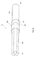
- FIG. 3 is a schematic representation of a detection catheter 1b according to a second embodiment.
- the detection device 1b according to the second embodiment of the invention is a biofunctionalized, medical detection catheter for the invasive (in vivo) enrichment of rare cells, biomolecules or drugs.
- a detection catheter or detector is also referred to as a medical nano-catheter (MN-K) or medical nano-catheter (MN-C).
- the detection device 1b comprises a guide element 40b.
- the guide element 40b can be designed as a flexible, medical guide wire, for example made of a metallic material, or as a plastic thread.
- the guide member 40b has a distal end 44b and a proximal end 46b. At the distal end 44b, a thickening 48b is formed as a boundary.
- the detection device 1b comprises a stabilizing element 60b, which is arranged to stabilize and fix the guide element 40b.
- the stabilizing element may comprise a sleeve 61 b, through which the guide member 40b is passed.
- the sleeve 61b may also be connected via its proximal end 64b to a push-pull device 68b.
- the guide member 40b may be connected via the proximal end 46b to the push-pull device 68b, so as to be moved by means of the push-pull device 68b relative to the sleeve 61b.
- the sleeve 61 b has at its distal end 66b further on a Luer-lock thread for connection with indwelling cannulas.
- the detection device 1b further comprises at least two functional elements 50b, which are pushed onto the guide element 40b or plugged.
- the functional elements may be ring segments 50b, which may, for example, be spherical or bone-shaped. In the in Fig. 3 shown longitudinal cross section, the functional elements have a bone shape. In a state in which the functional elements 50 b are pushed or attached to the guide member 40 b, this undergoes a stabilization, without the flexibility is completely lost.
- the functional elements 50b on the guide member 40b this must be separated from the push-pull device 68b and located outside of the sleeve 61 b.
- the functional elements 50b can accordingly be pushed or pushed onto the latter from the proximal end 46b of the guide element 40b.
- the first deferred functional element 50b abuts the boundary 48b at the distal end 44b of the guide element 40b.
- Each further functional element 50b, which is pushed onto the functional element 40b can come to rest on the respective previously suspended functional element 50b.
- the guide element 40b After arranging the respectively required number of functional elements 50b, the guide element 40b can be pushed into the sleeve 61b via its proximal end 46b.
- the proximal end 46b of the guide member 40b may be led out of the sleeve 61b by the proximal end 64b of the sleeve 61b to be connected to the push-pull device 68b. This can subsequently be connected to the proximal end 64b of the sleeve 61b.
- the functional elements 50b can be stored within the sleeve 61b.
- an indwelling cannula connected to the distal end 66b of the sleeve 61b is introduced into a human body.
- the guide element 40b together with functional elements 50b can now be applied from the sleeve 61b into the respective body opening and subsequently moved back into the sleeve 61b.
- the push-pull device 68b is released from the sleeve 61b, then the guide element of FIG the push-pull device 68b removed and from the sleeve 61 b pulled out.
- the functional elements 50b can then be removed individually from the guide element 40b.
- Each of the functional elements 50b has a functional surface 10 equipped with detection receptors 12, reference being made to the preceding description of the first exemplary embodiment.
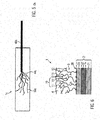
- FIG. 5a is a schematic representation of a detection catheter 1c according to a third embodiment.
- the detection device 1c according to the invention according to the second embodiment is a biofunktionalformaten, medical detection catheter for the invasive (in vivo) enrichment of rare cells, biomolecules or drugs.
- a detection catheter or detector is also referred to as a medical nano-catheter (MN-K) or medical nano-catheter (MN-C).
- the inventive detection device 1c according to the third embodiment comprises a flexible medical guide wire 40c, with a distal end 44c and a proximal end.
- the detection device 1c according to the third embodiment may further be equipped with a stabilizing element in the form of a sleeve (not shown here) and a pulling / pushing device (not shown here).
- a stabilizing element in the form of a sleeve (not shown here) and a pulling / pushing device (not shown here).
- the detection device 1c further comprises at least two functional elements 50c, which are formed as threads.
- the threads 50c are fixedly connected to the free end 44c of the guide wire 40c according to the third embodiment.
- the threads 50c have a smaller thickness than the guide wire 40c.
- the thickness of the threads 50c should be selected such that no thromboses are caused during use.
- the thickness of the threads should be chosen so that they do not stick together, but spread evenly in the bloodstream.
- the flexibility of the threads 50c can ensure, in use of a detection device 1c, that the entire vein cross-section is covered and, moreover, there is freedom of movement in the longitudinal direction and transversely to the longitudinal direction of the respective vein.
- the threads 50c thus form a structure in the manner of a "tentacle” in use.
- the coverage achieved thereby of the entire vein cross-section ensure good collection of sample material from the blood.
- the threads 50c can be individually cut or torn off the guide wire 40c.
- Each of the functional elements 50c has a functional surface 10 equipped with detection receptors 12, reference being made to the preceding description of the first or second exemplary embodiment.
- FIG. 5b is a schematic representation of a detection catheter 1d according to a fourth embodiment.
- the detection device 1c according to the invention according to the second embodiment is a biofunktionalformaten, medical detection catheter for the invasive (in vivo) enrichment of rare cells, biomolecules or drugs.
- a detection catheter or detector is also referred to as a medical nano-catheter (MN-K) or medical nano-catheter (MN-C).
- the inventive detection device 1d according to the fourth embodiment comprises a flexible, medical guide wire 40d, with a distal end 44d and a proximal end 46d.
- the detection device 1d according to the fourth embodiment may further be equipped with a pulling / pushing device (not shown here).
- a pulling / pushing device not shown here.
- the detection device 1 d further comprises at least two functional elements 50d, preferably more than two functional elements 50d, which are formed as wires.
- the wires 50d are firmly connected to the free distal end 44d of the guide wire 40d according to the fourth embodiment, in particular welded.
- the detection device 1d can furthermore be equipped with a stabilizing element 60d in the form of a sleeve, which preferably covers, in particular surrounds, the connection point between the wires 50d and the distal end 44d of the guide wire 40d.
- the wires 50d are connected to each other at their distal ends 52d, in particular welded together, so that the wires 50d as a whole form a bundle of functional elements 50d.
- the wires 50d each have a smaller thickness than the guide wire 40d.
- the thickness of the wires 50d should in particular be chosen so that no thromboses are caused during use. At the same time, the thickness of the wires 50d should be chosen so that they can be guided well in the bundle through the guide wire 40d.
- the wires 50d can be individually cut or torn off the guide wire 40d.
- Each of the functional elements 50d has a functional surface 10 equipped with detection receptors 12, with reference being made to the preceding description of the first or second exemplary embodiment.
- the functional surface 10 may be formed on a carrier 2.
- the carrier 2 may be part of a functional element 50a, 50b or 50c.
- An exemplary layer structure of a carrier 2 is shown in FIG FIG. 6 shown.
- a substrate 21 made of medical grade stainless steel wire with a diameter of about 0.5 mm gives the support 2 its visible structure.
- the substrate 21 may include one or more coatings 22, 23.
- the substrate 21 is coated with a gold coating 22 having a thickness of 0.5 to 1.0 microns, which is applied by electroplating, ceramic methods, cementation or by vapor deposition.
- the substrate 21 may further be coated with a biocompatible dye to reduce intrinsic fluorescence of the base material during microscopic evaluation.
- the chemical activation of the carrier 2 is carried out via an affinity reaction usually by sulfur or nitrogen-containing compounds to which in turn directly or via polymer chains specific detection receptors 12 can be bound.
- a covalent secondary layer consisting of a functional biocompatible polymer 3 is applied to the carrier 2 by wet-chemical or physical methods.
- the layer thickness can be 1 to 2 microns.
- the carrier 2 is chemically activated.
- specific antibodies in particular monoclonal antibodies of murine origin, chimeric antibodies, humanized antibodies, or fragments of these antibodies or amino acid structures or nucleic acid structures or synthetic structures with specific affinity to cell surfaces or molecules can be covalently attached as detection receptors ,
- a complex sample fluid such as blood is not only a permanent connection of the detection receptors 12 while preserving the biological function, but also an efficient suppression of nonspecific adsorption processes for the selective attachment of ligands of crucial importance.
- An intermediate layer 23 here has the task of ensuring an effective shielding of the surface of the substrate 21 and at the same time to provide the functional groups for binding the biocompatible polymer layer 3 in sufficient density.
- the interlayer system accordingly forms an adhesion promoter between the gold coating 22 of the substrate 21 and the biocompatible polymer layer 3.
- the biocompatible polymer 3 is preferably a hydrogel with carbon-containing long branched macromolecules which have a high number of functional groups, for example carboxyl groups or polycarboxylates.
- the nature of the functional groups depends on the molecular properties of the specific detection receptors 12.
- the biocompatible hydrogel thereby ensures the permanent covalent binding of the detection receptors 12 while preserving the biological function and at the same time prevents the detection receptors 12 from being impaired in their recognition function by nonspecific adsorption phenomena.
- Hydrogels are three-dimensionally crosslinked hydrophilic polymers that absorb liquids, such as water, but are themselves insoluble therein. Main constituents of the hydrogel are polyacrylic acid (PAA) and polyethylene glycol (PEG).
- Property profiles can be tailor-made according to the desired requirements or areas of application via a suitable selection of the monomer building blocks, the degree of crosslinking and the crosslinking density.
- An essential property is the biocompatibility, ie the compatibility of the hydrogel with the living tissue.
- the branched polymer chains of the biocompatible polymer 3 also prevent the thrombogenic effect during invasive use.
- the functional groups receive an unbalanced molecular charge that allows electrostatically attracting and covalently binding dissolved detection receptors 12 from a solution.
- the detection receptors 12 permanently immobilized on the polymer layer 3 serve for the specific binding of the ligands or target molecules and target cells their surface antigens and thus enable the function of the detection device 1.
- chemically or enzymatically cleavable groups can be contained in this biocompatible polymer 3 in order to facilitate the quantitative recovery of bound target molecules or cells.
- the branched molecular structures of the biocompatible polymer 3 form a three-dimensionally structured functional area 10 with mutually facing functional sections 11 and interspaces 13 which can be penetrated by sample liquid.
- the surface of the carrier 2 (shown in the macroscopic or visible region) is structured in a three-dimensional manner.
- FIG. 6 the sample liquid in an advantageous manner via the respective functional element 50a, 50b, 50c passes, slows down the three-dimensionally structured in the microscopic area functional surface 10 of the biocompatible polymer 3 passes, slows down the three-dimensionally structured in the microscopic area functional surface 10 of the biocompatible polymer 3 (see FIG. FIG. 6 ), the flow of the sample liquid in the region of the boundary layer and favors the enrichment of the ligands at the detection receptors 12th
- a biocompatible protective layer (tertiary layer or stabilizer layer) 4 is applied over the biocompatible polymer 3.
- This protective layer 4 dries over the secondary layer and forms a dense network of crystalline structures and thus stabilizes and conserves the functional part 1a of the catheter 1.
- the protective layer 4 is not covalently bound. In the bloodstream, the protective layer 4 goes into solution and releases the functional surface 10 of the catheter. Alternatively, the protective layer 4 can be washed off with sterile water before use.
- the protective layer 4 may comprise high purity alginates, polyethylene glycols, cyclic and non-cyclic oligosaccharides and polysaccharides, antioxidant amino acids, proteins and vitamins.
- the protective layer 4 is preferably made of a biocompatible high-viscosity polysaccharide, which serves as a medium for added amino acids, proteins, vitamins and stabilizing polysaccharides.
- the high viscosity allows rapid wettability of the surface.
- the deposited protective layer 4 adheres to the secondary coating and prevents the ingress of foreign substances during storage.
- the added amino acids, proteins and vitamins are present in higher concentrations compared to the specific ligands and thereby able to control the likelihood of damage to the target molecules by radical molecules or charge carriers and to restore destroyed chemical bonds by recombination processes.
- the completed detection device 1a, 1b, 1c is packaged in a low-germ environment. Final sterilization is by gamma-irradiation at a radiation dose of 25 kGy.
- the detection device 1a, 1b, 1c is intended for single use.
- a preferred application of the detection device 1a, 1b, 1c is in prenatal and cancer diagnostics.
- the detection device 1a, 1b, 1c can be used, for example, for isolating circulating fetal cells or tumor cells in the bloodstream of pregnant women or cancer patients.
- the detection device 1a, 1b, 1c is introduced into the vein via a suitable commercially available brown-eye system and applied to the venous blood circulation.
- the dwell time in the vein can be about 30 minutes.
- the cells bound to the detection device 1a, 1b, 1c are further enriched by means of targeted laboratory diagnostics and characterized in terms of molecular biology and cell biology.
- the aim of the minimally invasive procedure to be performed is the selection of fetal or tumor cells from the blood. Due to the low cell concentration of the cells in the blood, a blood sample of about 0.5 I would be necessary to obtain the desired target cell count. However, this is excluded from a medical perspective.
- chromosome aberration eg trisomy 21 (Down syndrome)
- the Down syndrome is diagnosed prenatal so far only by invasive procedures, each having a Abortrisiko 1%: chorionic villus sampling between the 11th and 14th week of pregnancy and amniocentesis (amniocentesis) from the 15th week of pregnancy.
- the method according to the invention which will be usable from the 9th week of pregnancy, has no risk for the fetus and can be used in the first-trimester screening.
- the amniocentesis can be dispensed with.
- Fetal trophoblast cells from the placenta can be detected from the 6th week of pregnancy in the bloodstream of the mother. Only about 2 to 5 of these cells per ml of maternal blood are present. These trophoblast cells have a membrane-bound HLA-G complex (antigen) that binds to specific antibodies.
- a specific HLA-G antibody is used as the detection receptor 12, which reacts only with membrane-bound HLA-G (antigen) and thus to catch only the desired fetal cells from the mother's blood.
- Cancer tumor cells can be enriched with the EpCAM antibody (against the EpCAM antigen), which is humanized in its constant domains and covalently attached to the hydrogel.
Abstract
Die Erfindung betrifft eine Detektionsvorrichtung zur in vivo und/oder in vitro Anreicherung von Probenmaterial, umfassend eine mit Detektionsrezeptoren bestückte Funktionsfläche. Um unter Verwendung einer Detektionsvorrichtung der eingangs genannten Art die Diagnose unterschiedlicher Krankheiten mit verringertem Aufwand und verbesserter Diagnosepräzision zu gewährleisten ist erfindungsgemäß vorgesehen, dass die Detektionsvorrichtung wenigstens ein Führungselement und zumindest zwei an dem Führungselement angeordnete Funktionselemente aufweist, an denen jeweils eine mit Detektionsrezeptoren bestückte Funktionsfläche ausgebildet ist, wobei die Funktionselemente voneinander lösbar ausgebildet und/oder einzeln von dem Führungselement lösbar sind. Ferner stellt die Erfindung eine Verwendung sowie ein Verfahren zur Anwendung der Detektionsvorrichtung bereit.The invention relates to a detection device for in vivo and / or in vitro enrichment of sample material comprising a functional surface equipped with detection receptors. In order to ensure the diagnosis of different diseases with reduced effort and improved diagnostic precision using a detection device of the type mentioned above, the detection device has at least one guide element and at least two functional elements arranged on the guide element, on each of which a functional surface populated with detection receptors is formed is, wherein the functional elements are detachably formed from each other and / or individually detachable from the guide element. Furthermore, the invention provides a use as well as a method of using the detection device.
Description
Die Erfindung betrifft eine Detektionsvorrichtung zur in vivo und/oder in vitro Anreicherung von Probenmaterial, umfassend eine mit Detektionsrezeptoren bestückte Funktionsfläche.The invention relates to a detection device for in vivo and / or in vitro enrichment of sample material comprising a functional surface equipped with detection receptors.
Viele Zelltypen, Moleküle, Tumor- und Biomarker sind in Körperflüssigkeiten zwar vorhanden, können aber oft wegen ihrer niedrigen Konzentration nicht effizient genug durch die herkömmlichen Methoden der Anreicherung gewonnen werden, um anschließend in etablierten diagnostischen Verfahren der klinischen Chemie, Pathologie oder Zytologie genutzt werden zu können.Many cell types, molecules, tumor and biomarkers are present in body fluids, but often can not be efficiently recovered by conventional enrichment methods because of their low concentration, and then used in established diagnostic procedures of clinical chemistry, pathology or cytology can.
Zum Beispiel ist das Anreichern von speziellen Zellen, insbesondere zirkulierenden Tumorzellen, aus einer Blutprobe außerhalb des Körpers eines Patienten (in vitro) mittels kommerziell erhältlicher paramagnetischer Nanopartikel und/oder Dichtegradientenzentrifugation möglich, jedoch in nur sehr begrenzter Anzahl und mit dem Nachteil, dass die Nanopartikel an oder in der Zelle binden und diese damit schädigen bzw. die Diagnostik erschweren können. Eine dieser kommerziellen Methoden spiegelt sich in einem Test wieder, in dem z.B. zirkulierende Tumorzellen aus 7,5 ml Blutvolumen mittels paramagnetischer Nanopartikel angereichert werden, um dann Aussagen über den Krankheitsverlauf machen zu können.For example, enrichment of specific cells, particularly circulating tumor cells, from a blood sample outside the body of a patient (in vitro) using commercially available paramagnetic nanoparticles and / or density gradient centrifugation is possible, but in only a very limited number and with the disadvantage that the nanoparticles bind to or in the cell and thereby damage them or make the diagnosis difficult. One of these commercial methods is reflected in a test in which e.g. circulating tumor cells from 7.5 ml of blood volume are enriched by means of paramagnetic nanoparticles in order then to be able to make statements about the course of the disease.
Der limitierende Faktor dieser Methode ist das gewonnene Probevolumen, welches beim Anwenden einer Detektionsvorrichtung zur Anreicherung von Probenmaterial innerhalb des Körpers eines Patienten (in vivo), z. B. eines funktionalisierten Katheter, um ein Vielfaches höher ist. Gefäßkatheter für die Anwendung medizinischer Interventionen sind meist zylinderförmig konstruiert. Der Vorteil dieser Form ist der relativ geringe Reibungswiderstand. Dennoch besteht bei dieser Form die Gefahr, dass der Blutstrom in kleineren Blutgefäßen verengt wird und dies zur Ausbildung einer Thrombose führt.The limiting factor of this method is the sample volume gained when applying a detection device for the accumulation of sample material within the body of a patient (in vivo), e.g. B. a functionalized catheter is many times higher. Vascular catheters for the application of medical interventions are usually cylindrical. The advantage of this form is the relatively low frictional resistance. However, there is a risk in this form of narrowing the blood stream in smaller blood vessels and causing thrombosis.
Aus dem Stand der Technik in der
Der Erfindung liegt die Aufgabe zugrunde, eine Detektionsvorrichtung der eingangs genannten Art anzugeben, mittels der die Diagnose unterschiedlicher Krankheiten mit verringertem Aufwand und verbesserter Diagnosepräzision erfolgen kann.The invention has for its object to provide a detection device of the type mentioned, by means of the diagnosis of different diseases can be done with reduced effort and improved diagnostic precision.
Um die der Erfindung zugrunde liegende Aufgabe zu lösen, wird eine Detektionsvorrichtung zur in vivo und/oder in vitro Anreicherung von Probenmaterial bereit gestellt, welche wenigstens ein Führungselement zur Führung zumindest eines Funktionselements und zumindest zwei an dem Führungselement angeordnete Funktionselemente aufweist, an denen jeweils eine mit Detektionsrezeptoren bestückte Funktionsfläche ausgebildet ist, wobei die Funktionselemente voneinander lösbar ausgebildet und/oder einzeln von dem Führungselement lösbar sind.In order to solve the object underlying the invention, a detection device for in vivo and / or in vitro enrichment of sample material is provided, which has at least one guide element for guiding at least one functional element and at least two arranged on the guide element functional elements, to each of which formed with detection receptors functional surface is formed, wherein the functional elements are detachable from each other and / or individually detachable from the guide element.
Durch die voneinander lösbare Ausgestaltung der Funktionselemente und/oder durch die einzeln von dem Führungselement lösbare Anordnung der Funktionselemente können diese unterschiedlichen Diagnoseverfahren unabhängig voneinander zugeführt werden. Die Diagnostik unterschiedlicher Krankheiten kann hierdurch zielgerichteter und damit unter verringertem Aufwand durchgeführt werden.Due to the detachable design of the functional elements and / or by the individually detachable from the guide element arrangement of the functional elements, these different diagnostic methods can be supplied independently. The diagnosis of different diseases can be carried out more targeted and thus with less effort.
Die Funktionsfläche eines Funktionselementes kann mit chemisch identischen oder chemisch verschiedenen Detektionsrezeptoren bestückt sein. Somit können bei einer Anwendung nach Bedarf auch verschiedene Liganden an einer Funktionsfläche angereichert werden. In bevorzugter Weise ist die Funktionsfläche eines Funktionselements jedoch mit Detektionsrezeptoren oder einer Kombination von Detektionsrezeptoren bestückt, die sich von den Detektionsrezeptoren oder der Kombination von Detektionsrezeptoren auf der Funktionsfläche des jeweils anderen Funktionselements unterscheiden.The functional surface of a functional element can be equipped with chemically identical or chemically different detection receptors. Thus, in one application as needed, different ligands can be enriched on a functional surface. Preferably, however, the functional surface of a functional element is equipped with detection receptors or a combination of detection receptors which differ from the detection receptors or the combination of detection receptors on the functional surface of the respective other functional element.
Im Sinne dieser Erfindung werden alle Strukturen, insbesondere Rezeptoren oder Liganden, die geeignet sind, Zielmoleküle und Zielzellen einzufangen, als Detektionsrezeptoren bezeichnet. Ferner werden alle Zielmoleküle und Zielzellen, die an den Detektionsrezeptoren andocken können, vereinfachend als Liganden bezeichnet. Der Begriff Probenflüssigkeit bezeichnet eine in flüssiger Form vorliegende Probe.For the purposes of this invention, all structures, in particular receptors or ligands which are suitable for capturing target molecules and target cells, are referred to as detection receptors. Furthermore, all target molecules and target cells that can dock at the detection receptors are referred to simply as ligands. The term sample fluid refers to a sample in liquid form.
Im folgenden soll sich die Bezeichnung proximal auf eine Richtung, ein Ende beziehungsweise einen Endabschnitt beziehen, die oder der einem potentiellen Bediener der Detektionsvorrichtung zugeordnet ist. Demgegenüber soll sich die Bezeichnung distal auf eine Richtung, ein Ende beziehungsweise einen Endabschnitt beziehen, die oder der einem potentiellen Patienten oder eines zu untersuchenden Probenmaterials zugeordnet ist.In the following, the term should refer proximally to a direction, an end or an end portion which is assigned to a potential operator of the detection device. In contrast, the term should refer distally to a direction, an end or an end portion, which is assigned to a potential patient or a sample material to be examined.
Bevorzugte Weiterbildungen der Erfindung sind Gegenstände der Unteransprüche.Preferred developments of the invention are subject matter of the subclaims.
In einer vorteilhaften Ausführung der Erfindung erfüllt das Führungselement vorzugsweise wenigstens eine der folgenden Anforderungen:
- Das Führungselement ist zumindest abschnittsweise als Draht ausgebildet.
- Das Führungselement ist zumindest abschnittsweise federelastisch ausgebildet.
- Das Führungselement ist zumindest abschnittsweise als flexibler medizinischer Führungsdraht ausgebildet.
- Das Führungselement ist zumindest abschnittsweise als Faden ausgebildet.
- Das Führungselement ist zumindest abschnittsweise als flexibler Kunststofffaden ausgebildet.
- Das Führungselement ist zumindest abschnittsweise als Katheter ausgebildet.
- Das Führungselement weist einen Aufnahmeabschnitt zur Aufnahme zumindest eines Funktionselements auf.
- Das Führungselement weist ein distales Ende sowie ein proximales Ende auf, wobei zwischen dem distalen und dem proximalen Ende ein Aufnahmeabschnitt zur Aufnahme zumindest eines Funktionselements ausgebildet ist.
- Das Führungselement ist zumindest abschnittsweise schraubenförmig ausgebildet.
- Das Führungselement weist an seinem Außenumfang zumindest abschnittsweise ein Außengewinde auf.
- Das Führungselement weist ein distales Ende sowie ein proximales Ende auf, wobei das distale Ende in ein Blutgefäß einführbar ist.
- Das Führungselement weist ein distales sowie ein proximales Ende auf, wobei das distale Ende verdickt ausgebildet ist.
- Das Führungselement weist ein distales Ende sowie ein proximales Ende auf, wobei das proximale Ende mit einem Stabilisierungselement verbunden ist.
- Das Führungselement ist in ein Innengewinde des Stabilisierungselements eingeschraubt.
- Das Führungselement ist aus einem metallischen und/oder nicht-metallischen Material gefertigt.
- Das Führungselement weist an seinem distalen Abschnitt eine mit Detektionsrezeptoren bestückte Funktionsfläche auf.
- The guide element is at least partially formed as a wire.
- The guide element is at least partially resilient.
- The guide element is formed at least in sections as a flexible medical guide wire.
- The guide element is at least partially formed as a thread.
- The guide element is at least partially formed as a flexible plastic thread.
- The guide element is at least partially formed as a catheter.
- The guide element has a receiving portion for receiving at least one functional element.
- The guide element has a distal end and a proximal end, wherein between the distal and the proximal end of a receiving portion for receiving at least one functional element is formed.
- The guide element is at least partially helical.
- The guide element has on its outer circumference, at least in sections, an external thread.
- The guide member has a distal end and a proximal end, the distal end being insertable into a blood vessel.
- The guide element has a distal and a proximal end, wherein the distal end is formed thickened.
- The guide element has a distal end and a proximal end, wherein the proximal end is connected to a stabilizing element.
- The guide element is screwed into an internal thread of the stabilizing element.
- The guide element is made of a metallic and / or non-metallic material.
- The guide element has at its distal portion on a equipped with detection receptors functional surface.
Gemäß einer weiteren vorteilhaften Ausführung der Erfindung ist das Führungselement mit einem Stabilisierungselement zur Stabilisierung des wenigstens einen Führungselements verbunden, welches vorzugsweise wenigstens eine der folgenden Anforderungen erfüllt:
- Das Stabilisierungselement ist dazu ausgebildet, das Führungselement zumindest abschnittsweise zu stabilisieren.
- Das Stabilisierungselement ist aus Kunststoff oder Metall gefertigt.
- Das Stabilisierungselement ist mit einem proximalen Ende oder einem proximalen Endabschnitt des Führungselements verbunden.
- Das Stabilisierungselement ist lösbar mit dem Führungselement verbunden.
- Das Stabilisierungselement ist form-, kraft- und/oder stoffschlüssig mit dem Führungselement verbunden.
- Das Stabilisierungselement ist mit dem Führungselement verklebt oder verschweißt.
- Das Stabilisierungselement ist zumindest abschnittsweise zylindrisch ausgebildet.
- Das Stabilisierungselement ist zumindest abschnittsweise als Hülse ausgebildet.
- Das Stabilisierungselement weist zumindest abschnittsweise ein Innengewinde auf.
- Das Stabilisierungselement ist zumindest abschnittsweise auf einen proximalen Abschnitt des Führungselementes aufgeschoben, aufgesteckt oder aufgeschraubt.
- Das Stabilisierungselement ist zumindest abschnittsweise auf einen distalen Abschnitt des Führungselementes aufgeschoben, aufgesteckt oder aufgeschraubt.
- Das Stabilisierungselement führt das Führungselement zumindest abschnittsweise.
- Das Stabilisierungselement führt das Führungselement beweglich.
- Das Stabilisierungselement ist als Abdeckvorrichtung für zumindest ein Funktionselement ausgebildet.
- Das Stabilisierungselement weist eine Aufnahme auf, in der die zumindest zwei Funktionselemente angeordnet sind.
- Das Stabilisierungselement ist in ein Blutgefäß einführbar.
- Das Stabilisierungselement weist eine Aufnahme auf, in der die zumindest zwei Funktionselemente herausführbar angeordnet sind.
- Das Stabilisierungselement weist ein distales und ein proximales Ende auf, wobei an dem distalen Ende ein Gewinde, insbesondere ein Luer-Lock-Gewinde zum Anschließen von Verweilkanülen, ausgebildet ist.
- Das Stabilisierungselement weist eine Druck-Zug-Vorrichtung auf, mittels der die zumindest zwei Funktionselemente aus der Hülse heraus- und wieder in diese hineinführbar sind.
- Das Stabilisierungselement weist zumindest einen Abschnitt auf, dessen Aussendurchmesser dem Aussendurchmesser des distalen Abschnitts des Führungselements entspricht oder im Wesentlichen entspricht.
- Das Stabilisierungselement ist mit dem Führungselement in einem Herstellverfahren gefertigt.
- Das Stabilisierungselement weist ein abgerundetes Ende als Verletzungsschutz auf.
- Das Stabilisierungselement ist zur Stabilisierung der Verbindungsstelle zwischen zumindest einem der Funktionselemente sowie dem Führungselement ausgebildet.
- The stabilizing element is designed to stabilize the guide element at least in sections.
- The stabilizing element is made of plastic or metal.
- The stabilizing element is connected to a proximal end or a proximal end portion of the guide element.
- The stabilizing element is releasably connected to the guide element.
- The stabilizing element is positively, positively and / or materially connected to the guide element.
- The stabilizing element is glued or welded to the guide element.
- The stabilizing element is at least partially cylindrical.
- The stabilizing element is at least partially formed as a sleeve.
- The stabilizing element has an internal thread at least in sections.
- The stabilizing element is at least partially pushed onto a proximal portion of the guide element, plugged or screwed.
- The stabilizing element is at least partially pushed onto a distal portion of the guide element, plugged or screwed.
- The stabilizing element guides the guide element at least in sections.
- The stabilizing element movably guides the guide element.
- The stabilizing element is designed as a covering device for at least one functional element.
- The stabilizing element has a receptacle in which the at least two functional elements are arranged.
- The stabilizing element is insertable into a blood vessel.
- The stabilizing element has a receptacle in which the at least two functional elements are arranged to be removable.
- The stabilizing element has a distal end and a proximal end, wherein a thread, in particular a Luer-lock thread for connecting indwelling cannulas, is formed at the distal end.
- The stabilizing element has a push-pull device by means of which the at least two functional elements can be guided out of the sleeve and back into it.
- The stabilizing element has at least one section whose outside diameter corresponds or substantially corresponds to the outside diameter of the distal section of the guide element.
- The stabilizing element is manufactured with the guide element in a manufacturing process.
- The stabilizing element has a rounded end for protection against injury.
- The stabilizing element is designed to stabilize the connection point between at least one of the functional elements and the guide element.
Gemäß einer noch weiteren vorteilhaften Ausgestaltung der Erfindung ist ferner eine Abdeckvorrichtung vorgesehen, die wenigstens eine der folgenden Anforderungen erfüllt:
- Die Abdeckvorrichtung ist zur Abdeckung zumindest eines der Funktionselemente ausgebildet.
- Die Abdeckvorrichtung ist Bestandteil des Stabilisierungselements.
- Die Abdeckvorrichtung ist als von dem Stabilisierungselement diskrete Komponente ausgebildet.
- Die Abdeckvorrichtung ist dazu ausgebildet, das Führungselement zumindest abschnittsweise zu stabilisieren.
- Die Abdeckvorrichtung ist aus Kunststoff oder Metall gefertigt.
- Die Abdeckvorrichtung ist zumindest abschnittsweise zylindrisch ausgebildet.
- Die Abdeckvorrichtung weist eine longitudinale Bohrung auf, zur Aufnahme zumindest eines Funktionselements.
- Die Abdeckvorrichtung ist zumindest abschnittsweise als Hülse ausgebildet.
- Die Abdeckvorrichtung ist zumindest abschnittsweise auf einen proximalen Abschnitt des Führungselementes aufgeschoben, aufgesteckt oder aufgeschraubt.
- Die Abdeckvorrichtung ist in ein Blutgefäß einführbar.
- Die Abdeckvorrichtung weist eine Aufnahme auf, in der die zumindest zwei Funktionselemente herausführbar angeordnet sind.
- Die Abdeckvorrichtung ist entlang einer Längsorientierung relativ zu den Funktionselementen und/oder relativ zum Stabilisierungselement beweglich angeordnet.
- Die Abdeckvorrichtung weist ein distales und ein proximales Ende auf, wobei an dem distalen Ende ein Gewinde, insbesondere ein Luer-Lock-Gewinde zum Anschließen von Verweilkanülen, ausgebildet ist.
- Die Abdeckvorrichtung weist Homopolymere, Copolymere, Biopolymere, chemisch modifizierte Polymere und/oder synthetische Polymere auf.
- Die Abdeckvorrichtung weist ein abgerundetes Ende als Verletzungsschutz auf.
- Die Abdeckvorrichtung ist zur Abdeckung der Verbindungsstelle zwischen zumindest einem der Funktionselemente sowie dem Führungselement ausgebildet.
- The covering device is designed to cover at least one of the functional elements.
- The covering device is part of the stabilizing element.
- The cover device is formed as a discrete component of the stabilizing element.
- The covering device is designed to stabilize the guide element at least in sections.
- The cover device is made of plastic or metal.
- The covering is at least partially cylindrical.
- The covering device has a longitudinal bore, for receiving at least one functional element.
- The covering is at least partially formed as a sleeve.
- The cover device is at least partially pushed onto a proximal portion of the guide element, plugged or screwed.
- The covering device can be inserted into a blood vessel.
- The covering device has a receptacle in which the at least two functional elements are arranged to be removable.
- The covering device is arranged to be movable along a longitudinal orientation relative to the functional elements and / or relative to the stabilizing element.
- The covering device has a distal end and a proximal end, wherein a thread, in particular a Luer-lock thread for connecting indwelling cannulas, is formed at the distal end.
- The cover device comprises homopolymers, copolymers, biopolymers, chemically modified polymers and / or synthetic polymers.
- The covering device has a rounded end as protection against injury.
- The covering device is designed to cover the connection point between at least one of the functional elements and the guide element.
Gemäß einer weiterhin vorteilhaften Ausgestaltung der Erfindung erfüllt zumindest eines der Funktionselemente wenigstens eine der folgenden Anforderungen erfüllt:
- Das Funktionselement ist zumindest teilweise aus Metall, vorzugsweise Edelstahl, medizinischem Edelstahl oder Titan; aus Glas, vorzugsweise Glasfaser; aus Kunststoff, vorzugsweise einem geschäumten Kunststoff, einem Polymer, bevorzugt Polyethylen, Polypropylen, Polyurethan, Polytetrafluorethylen, einem auf organischen Polymeren basierenden Kunststoff oder einer Kombination dieser Materialien gefertigt.
- Das Funktionselement ist als flexibler Faden ausgebildet, der bevorzugt einen geringere Dicke und/oder eine größere Flexibilität als das Führungselement aufweist.
- Das Funktionselement ist an dem distalen Ende des Führungselements, insbesondere an einer Querschnittsfläche des distalen Endes, befestigt.
- Das Funktionselement ist an dem Außenumfang des Führungselements befestigt, wobei die Länge des Funktionselements bevorzugt größer ist als der Abstand der Verbindungsstelle am Außenumfang des Führungselements vom distalen Ende des Führungselements.
- Das Funktionselement ist an seinem distalen Ende mit wenigstens einem weiteren Funktionselement, vorzugsweise mit wenigstens zwei weiteren Funktionselementen verbunden, vorzugsweise stoffschlüssig verbunden.
- Das Funktionselement ist als Draht, insbesondere als flexibler Draht ausgebildet, der bevorzugt einen geringere Dicke und/oder eine größere Flexibilität als das Führungselement aufweist.
- Das Funktionselement ist an dem distalen Ende des Führungselements, insbesondere an einer Querschnittsfläche des distalen Endes, befestigt, insbesondere stoffschlüssig befestigt, insbesondere an der Querschnittsfläche des distalen Endes angeschweißt.
- Das Funktionselement ist an seinem distalen Ende mit wenigstens einem weiteren Funktionselement, vorzugsweise mit wenigstens zwei weiteren Funktionselementen verbunden, insbesondere stoffschlüssig verbunden, insbesondere verschweißt.
- Das Funktionselement ist zerstörungsfrei von dem zumindest einen anderen Funktionselement lösbar und/oder zerstörungsfrei von dem Führungselement abnehmbar.
- Das Funktionselement ist vom Führungselement abschneidbar oder abreißbar ist.
- Das Funktionselement ist durch ein ringförmiges Segment gebildet.
- Das Funktionselement weist eine Kugelform oder eine Knochenform auf.
- Das Funktionselement umfasst an dessen Innenumfangsfläche ein Innengewinde.
- Das Funktionselement umschließt zumindest einen Abschnitt des Führungselements.
- Das Funktionselement ist auf das Führungselement aufgeschoben, aufgesteckt oder aufgeschraubt.
- Das Funktionselement ist zwischen einem distalen Ende sowie einem proximalen Ende des Führungselements an diesem angeordnet.
- Das Funktionselement weist Detektionsrezeptoren auf, die sich von den Detektionsrezeptoren des jeweils anderen Funktionselements unterscheiden.
- Das Funktionselement weist eine Kombination von Detektionsrezeptoren auf, die sich von der Kombination von Detektionsrezeptoren des jeweils anderen Funktionselements unterscheidet.
- Das Funktionselement weist zumindest einen Abschnitt mit einem Aussendurchmesser auf, der dem Aussendurchmesser des distalen Abschnitts des Führungselements entspricht oder im Wesentlichen entspricht.
- Das Funktionselement weist zumindest einen Abschnitt mit einem Aussendurchmesser auf, der größer oder kleiner ist als der distale Abschnitt des Führungselements, insbesondere 0,01 mm bis 0,1 mm kleiner ist als der distale Abschnitt des Führungselements.
- Das Funktionselement ist als Stent, Katheter oder Katheterabschnitt ausgebildet.
- Das Funktionselement ist als Mandrain ausgebildet.
- Das Funktionselement ist mit Erhöhungen, Vertiefungen und/oder Verzweigungen ausgebildet.
- Das Funktionselement umfasst zumindest teilweise eine spiralförmige, schraubenförmige, schneckenförmige, wellenförmige, helikale, filamentöse, bürstenförmige, kammförmige, netzförmige, poröse, schwammförmige oder dergleichen Struktur.
- Das Funktionselement umfasst eine Beschichtung aus Metall, vorzugsweise aus einem Metall aus der 10.
oder 11. Gruppe des Periodensystems der Elemente, bevorzugt aus Nickel, Kupfer, Palladium, Silber, Platin und/oder Gold.
- The functional element is at least partially made of metal, preferably stainless steel, medical grade stainless steel or titanium; of glass, preferably glass fiber; made of plastic, preferably a foamed plastic, a polymer, preferably polyethylene, polypropylene, polyurethane, polytetrafluoroethylene, a polymer based on organic polymers or a combination of these materials.
- The functional element is designed as a flexible thread, which preferably has a smaller thickness and / or greater flexibility than the guide element.
- The functional element is attached to the distal end of the guide element, in particular to a cross-sectional area of the distal end.
- The functional element is attached to the outer circumference of the guide element, wherein the length of the functional element is preferably greater than the distance of the connection point on the outer circumference of the guide element from the distal end of the guide element.
- The functional element is connected at its distal end to at least one further functional element, preferably connected to at least two further functional elements, preferably materially connected.
- The functional element is designed as a wire, in particular as a flexible wire, which preferably has a smaller thickness and / or greater flexibility than the guide element.
- The functional element is fastened to the distal end of the guide element, in particular to a cross-sectional surface of the distal end, in particular fixed in a material-locking manner, in particular welded to the cross-sectional surface of the distal end.
- The functional element is connected at its distal end with at least one further functional element, preferably with at least two further functional elements, in particular materially connected, in particular welded.
- The functional element is non-destructively removable from the at least one other functional element detachable and / or non-destructive of the guide element.
- The functional element is cut off from the guide element or can be torn off.
- The functional element is formed by an annular segment.
- The functional element has a spherical shape or a bone shape.
- The functional element comprises on its inner circumferential surface an internal thread.
- The functional element encloses at least a portion of the guide element.
- The functional element is pushed onto the guide element, plugged or screwed.
- The functional element is arranged between a distal end and a proximal end of the guide element at this.
- The functional element has detection receptors which differ from the detection receptors of the respective other functional element.
- The functional element has a combination of detection receptors, which differs from the combination of detection receptors of the respective other functional element.
- The functional element has at least one section with an outer diameter that corresponds to or substantially corresponds to the outer diameter of the distal section of the guide element.
- The functional element has at least one section with an outer diameter which is larger or smaller than the distal section of the guide element, in particular 0.01 mm to 0.1 mm smaller than the distal section of the guide element.
- The functional element is designed as a stent, catheter or catheter section.
- The functional element is designed as a mandrain.
- The functional element is formed with elevations, depressions and / or branches.
- The functional element at least partially comprises a helical, helical, helical, wavy, helical, filamentous, brush-shaped, comb-shaped, reticulated, porous, spongy or similar structure.
- The functional element comprises a coating of metal, preferably of a metal from the 10th or 11th group of the Periodic Table of the Elements, preferably of nickel, copper, palladium, silver, platinum and / or gold.
Gemäß einer weiteren Ausgestaltung der Erfindung erfüllt die Funktionsfläche zumindest eines Funktionselements wenigstens eine der folgenden Anforderungen:
- Die Funktionsfläche weist eine dreidimensionale Struktur mit einander zugewandten Funktionsabschnitten auf, die wenigstens einen von einer Probenflüssigkeit durchsetzbaren Zwischenraum bilden, wobei der Zwischenraum vorzugsweise wenigstens abschnittsweise kanalförmig ausgebildet ist, wobei bevorzugt mehrere Zwischenräume vorzugsweise ein verzweigtes Netz von Kanälen bilden.
- Die Funktionsfläche ist im makroskopischen und/oder im mikroskopischen Bereich dreidimensional strukturiert.
- Die Funktionsfläche ist mit Erhöhungen, Vertiefungen und/oder Verzweigungen ausgebildet.
- Die Funktionsfläche umfasst zumindest teilweise eine spiralförmige, schraubenförmige, schneckenförmige, wellenförmige, helikale, filamentöse, bürstenförmige, kammförmige, netzförmige, poröse, schwammförmige oder dergleichen Struktur.
- The functional surface has a three-dimensional structure with functional portions facing one another, which form at least one intermediate space permeable by a sample liquid, wherein the intermediate space is preferably channel-shaped at least in sections, with preferably several intermediate spaces preferably forming a branched network of channels.
- The functional area is three-dimensionally structured at the macroscopic and / or microscopic level.
- The functional surface is formed with elevations, depressions and / or branches.
- The functional surface at least partially comprises a helical, helical, helical, wavy, helical, filamentous, brush-shaped, comb-shaped, reticulated, porous, sponge-shaped or the like structure.
Die Funktionsabschnitte gelten als einander zugewandt, wenn sie einen Winkel von kleiner als 180 Grad einschließen, sich gegenseitig also "sehen" können. Dadurch weist die Detektionsvorrichtung gegenüber einer Detektionsvorrichtung mit einer glatten beziehungsweise zylindrischen Funktionsfläche eine größere Funktionsfläche auf. Ferner kann die Probenflüssigkeit in den Zwischenräumen ideal über die Funktionsfläche geleitet werden und an den Detektionsrezeptoren angereichert werden. Zudem können die an den Detektionsrezeptoren andockenden Liganden in den Zwischenräumen festgehalten und so vor Abrieb besser geschützt werden. Vorzugsweise kann die Funktionsfläche auch ein gewisses Volumen an Probenflüssigkeit speichern.The functional sections are considered to be facing each other when they enclose an angle of less than 180 degrees, so they can "see" each other. As a result, the detection device has a larger functional surface than a detection device with a smooth or cylindrical functional surface. Furthermore, the sample liquid in the intermediate spaces can be conducted ideally over the functional area and enriched at the detection receptors. In addition, the docking at the detection receptors ligands can be held in the interstices and thus better protected from abrasion. Preferably, the functional surface can also store a certain volume of sample liquid.
Es kann sich als hilfreich erweisen, wenn die Funktionsfläche zumindest eines Funktionselements im makroskopischen und/oder mikroskopischen Bereich dreidimensional strukturiert ist. Durch eine im makroskopischen bzw. sichtbaren Bereich dreidimensional strukturierte Funktionsfläche, die bspw. durch die sichtbare Geometrie der Detektionsvorrichtung bestimmt ist, kann die Probenflüssigkeit in vorteilhafter Weise über die Funktionsfläche geführt werden. Durch eine im mikroskopischen Bereich dreidimensional strukturierte Funktionsfläche kann die Strömungsgeschwindigkeit im Bereich der Grenzschicht verringert werden. Die Zwischenräume sind vorzugsweise mindestens derart dimensioniert, dass spezifische Liganden an den Detektionsrezeptoren andocken können. Vorzugsweise sind die Zwischenräume derart dimensioniert, dass in etwa die Anzahl an spezifischen Liganden aufgenommen und angeordnet werden können, die der Anzahl der Detektionsrezeptoren an den einander zugewandten Funktionsabschnitten entspricht. Dadurch wird die Funktionsfläche in idealer Weise genutzt. Ferner können die Liganden vor Abrieb noch besser geschützt werden.It may prove to be helpful if the functional area of at least one functional element is structured three-dimensionally in the macroscopic and / or microscopic range. By means of a functional surface which is structured three-dimensionally in the macroscopic or visible region and which is determined, for example, by the visible geometry of the detection device, the sample liquid can be advantageously guided over the functional surface. By a three-dimensionally structured in the microscopic area functional surface, the flow velocity be reduced in the area of the boundary layer. The interspaces are preferably at least dimensioned such that specific ligands can dock to the detection receptors. The intermediate spaces are preferably dimensioned such that approximately the number of specific ligands corresponding to the number of detection receptors on the mutually facing functional sections can be accommodated and arranged. As a result, the functional area is used in an ideal way. Furthermore, the ligands can be better protected against abrasion.
In einer vorteilhaften Ausführung der Erfindung ist der Zwischenraum wenigstens abschnittsweise kanalförmig ausgebildet, wobei mehrere Zwischenräume vorzugsweise ein verzweigtes Netz von Kanälen bilden. Der Kanal kann sich über die gesamte Länge der Funktionsfläche erstrecken. Dadurch kann Probenflüssigkeit ideal zu den Detektionsrezeptoren geleitet werden. Durch die Auslegung der Größe der Zwischenräume kann eine Fließgeschwindigkeit und Fließrichtung der Probenflüssigkeit beeinflusst werden. Vorzugsweise erstreckt sich der Kanal zumindest abschnittsweise in Längsrichtung der Detektionsvorrichtung, so dass durch den Kanal eine natürliche Fließrichtung der Probenflüssigkeit möglichst wenig beeinträchtigt wird.In an advantageous embodiment of the invention, the intermediate space is at least partially channel-shaped, wherein a plurality of intermediate spaces preferably form a branched network of channels. The channel can extend over the entire length of the functional surface. This allows sample fluid to be routed ideally to the detection receptors. By designing the size of the interstices, a flow velocity and flow direction of the sample liquid can be influenced. Preferably, the channel extends at least in sections in the longitudinal direction of the detection device, so that through the channel a natural flow direction of the sample liquid is impaired as little as possible.
Es kann von Vorteil sein, wenn die Funktionsfläche zumindest eines Funktionselements mit Erhöhungen, Vertiefungen und/oder Verzweigungen ausgebildet ist, und/oder zumindest teilweise eine spiralförmige, schraubenförmige, schneckenförmige, wellenförmige, helikale, filamentöse, bürstenförmige, kammförmige, netzförmige, poröse, schwammförmige oder dergleichen Struktur umfasst. Derartige Formen besitzen große Oberflächen und sind für die Anwendung in der erfindungsgemäßen Detektionsvorrichtung gut geeignet. Spiralförmige, schraubenförmige, schneckenförmige, wellenförmige, helikale Strukturen weisen i.d.R. einen geringen Reibungswiderstand auf. Dadurch wird die Strömung der Probenflüssigkeit, bspw. Blut in einem Blutgefäß, wenig beeinträchtigt, selbst wenn Teile der Funktionsfläche an den Gefäßwänden anliegen. Filamentöse, bürstenförmige, kammförmige, netzförmige, poröse und schwammförmige Strukturen verlangsamen die natürliche Strömung der Probenflüssigkeit und eignen sich hervorragend als Flüssigkeitsspeicher, wodurch die Anreicherung der Liganden an den Detektionsrezeptoren zusätzlich begünstigt wird.It may be advantageous if the functional surface of at least one functional element with elevations, depressions and / or branches is formed, and / or at least partially a helical, helical, helical, wavy, helical, filamentous, brush-shaped, comb-shaped, reticulate, porous, spongy or the like structure. Such molds have large surfaces and are well suited for use in the detection device according to the invention. Helical, helical, helical, wavy, helical structures have i.d.R. a low frictional resistance. As a result, the flow of the sample liquid, for example blood in a blood vessel, is little impaired, even if parts of the functional surface lie against the vessel walls. Filamentous, brush-shaped, comb-shaped, reticulated, porous and sponge-shaped structures slow down the natural flow of the sample fluid and are outstandingly suitable as a liquid reservoir, which additionally favors the enrichment of the ligands at the detection receptors.
Es kann sich als vorteilhaft erweisen, wenn die Detektionsrezeptoren Antikörper, Antikörperfragmente, Aminosäuren-Strukturen, Nukleinsäure-Strukturen, anorganische Materialen und/oder synthetische Strukturen mit spezifischer Affinität zu Zelloberflächen umfassen, vorzugsweise monoklonale Antikörper murinen Ursprungs, chimäre Antikörper oder humanisierte Antikörper, bevorzugt HLA-G und/oder EpCAM Antikörper.It may prove advantageous if the detection receptors comprise antibodies, antibody fragments, amino acid structures, nucleic acid structures, inorganic materials and / or synthetic structures with specific affinity to cell surfaces, preferably monoclonal antibodies of murine origin, chimeric antibodies or humanized antibodies, preferably HLA -G and / or EpCAM antibodies.
Es kann auch praktisch sein, wenn die Funktionsfläche zumindest eines Funktionselements gesättigte Atomgruppen und kovalent gebundene Liganden und Rezeptoren umfasst, um unerwünschte Wechselwirkungen mit Blutbestandteilen und die Anbindung von unspezifischen Zellen und Molekülen zu verhindern.It may also be practical if the functional surface of at least one functional element comprises saturated atomic groups and covalently bonded ligands and receptors to prevent undesired interactions with blood components and the attachment of nonspecific cells and molecules.
Die Handhabung der Detektionsvorrichtung kann ferner dadurch erleichtert werden, dass das Führungselement, die zumindest zwei Funktionselemente, das Stabilisierungselement und/oder die Abdeckvorrichtung zu einem Stilett zusammengefügt sind.The handling of the detection device can be further facilitated by the fact that the guide element, the at least two functional elements, the stabilizing element and / or the cover device are assembled into a stiletto.
Es kann aber auch praktisch sein, wenn dass das Führungselement, das Stabilisierungselement und/oder die Abdeckvorrichtung eine Markierung zur Applikationskontrolle aufweist. Dadurch kann die Detektionsvorrichtung im Einsatz besser kontrolliert werden.However, it can also be practical if the guide element, the stabilization element and / or the covering device has a mark for application control. As a result, the detection device can be better controlled in use.
In einer anderen vorteilhaften Ausführung der Erfindung weist zumindest eines der Funktionselemente ein biokompatibles Polymer auf, das vorzugsweise wenigstens eine der folgenden Anforderungen erfüllt:
- Das biokompatible Polymer ist als zusammenhängende Polymerschicht ausgebildet. Dadurch kann die gesamte Oberfläche des Funktionselements durch die Polymerschicht abgedeckt oder abgeschirmt werden. Die Dicke der Polymerschicht liegt vorzugsweise im Bereich von 0,1
bis 10 µm, bevorzugt im Bereich von 0,5 bis 5 µm, besonders bevorzugt im Bereich von 1bis 2 µm. - Das biokompatible Polymer weist eine dreidimensionale, vorzugsweise filamentöse und/oder poröse Struktur auf. Diese Struktur bildet viele Zwischenräume, welche durch die an den Detektionsrezeptoren andockenden Liganden im Wesentlichen gefüllt werden, so dass die Liganden vor Abrieb noch besser geschützt sind. Das biokompatible Polymer kann im makroskopischen und/oder im mikroskopischen Bereich dreidimensional strukturiert sein.
- Das biokompatible Polymer weist eine dreidimensionale, vorzugsweise filamentöse, und/oder poröse Oberfläche auf. Die Oberfläche des biokompatiblen Polymers kann im makroskopischen und/oder mikroskopischen Bereich dreidimensional strukturiert sein.
- Das biokompatible Polymer weist eine kohlenstoffhaltige, verzweigte Molekülstruktur auf. Diese Molekülstruktur eignet sich hervorragend für die Anbindung der Detektionsrezeptoren und die Anreicherung von Liganden an den Detektionsrezeptoren. Dabei bildet diese Molekülstruktur eine filamentöse Funktionsfläche im Sinne der Erfindung, die im mikroskopischen Bereich dreidimensional strukturiert ist. Die verzweigten Molekülstrukturen umfassen zahlreiche Zwischenräume, die von gegenüberstehenden und mit Detektionsrezeptoren bestückten Funktionsabschnitten in Form von Polymermolekülen gebildet sind. Diese Zwischenräume sind von einer Probenflüssigkeit durchsetzbar und bilden einen Flüssigkeitsspeicher, wodurch die Anreicherung der Liganden an den Detektionsrezeptoren besonders begünstigt wird. Im Bereich der Grenzschicht an einer mit dieser Molekülstruktur besetzten Oberfläche wird die Umströmung von einer Probenflüssigkeit erheblich verlangsamt. Dadurch wird die Anreicherung der Liganden zusätzlich begünstigt.
- Das biokompatible Polymer ist vorzugsweise über funktionelle Gruppen mit dem Funktionselement wirkverbunden, bevorzugt durch chemische Bindung, besonders bevorzugt durch kovalente Bindung.
- Das biokompatible Polymer umfasst funktionelle Gruppen, vorzugsweise Carboxyl-Gruppen, wobei die funktionellen Gruppen vorzugsweise durch chemische Aktivierung eine unausgeglichene Molekülladung aufweisen, wobei die funktionellen Gruppen bevorzugt auf die Detektionsrezeptoren abgestimmt sind.
- Das biokompatible Polymer weist hydrophile Eigenschaften auf und ist vorzugsweise ein Hydrogel.
- Das biokompatible Polymer umfasst chemisch und/oder enzymatisch spaltbare Gruppen, welche die Ablösung der Liganden erleichtert. Die chemisch und/oder enzymatisch spaltbaren Gruppen sind vorzugsweise die funktionellen Gruppen, an welchen die Detektionsrezeptoren gebunden sind.
- Das biokompatible Polymer umfasst gesättigte Atomgruppen und kovalent gebundene Detektionsrezeptoren, um unerwünschte Wechselwirkungen mit Blutbestandteilen und die Anbindung von unspezifischen Zellen und Molekülen zu verhindern.
- Das biokompatible Polymer ist in einem Hohlraum des Funktionselements angeordnet. Dadurch kann ein Hohlraum des Funktionselements zur Anreicherung von Liganden genutzt werden. Dort sind die Liganden vor Abrieb optimal geschützt.
- Das biokompatible Polymer ist vernetzt.
- Das biokompatible Polymer umfasst bzw. bildet die Funktionsfläche. Die Funktionsfläche befindet sich vorzugsweise an der Oberfläche des biokompatiblen Polymers. Das biokompatible Polymer kann direkt mit den Detektionsrezeptoren bestückt sein.
- The biocompatible polymer is formed as a coherent polymer layer. As a result, the entire surface of the functional element can be covered or shielded by the polymer layer. The thickness of the polymer layer is preferably in the range of 0.1 to 10 microns, preferably in the range of 0.5 to 5 microns, more preferably in the range of 1 to 2 microns.
- The biocompatible polymer has a three-dimensional, preferably filamentous and / or porous structure. This structure forms many spaces which are substantially filled by the ligands docking at the detection receptors, so that the ligands are even better protected against abrasion. The biocompatible polymer can be structured three-dimensionally in the macroscopic and / or microscopic range.
- The biocompatible polymer has a three-dimensional, preferably filamentous, and / or porous surface. The surface of the biocompatible polymer can be structured three-dimensionally in the macroscopic and / or microscopic range.
- The biocompatible polymer has a carbon-containing, branched molecular structure. This molecular structure is excellently suited for the binding of the detection receptors and the accumulation of ligands at the detection receptors. In this case, this molecular structure forms a filamentous functional surface in the sense of the invention, which in the microscopic Area is structured in three dimensions. The branched molecular structures comprise numerous interspaces formed by opposing and functional receptor segments in the form of polymer molecules. These interspaces are enforceable by a sample liquid and form a liquid reservoir, whereby the enrichment of the ligands is particularly favored at the detection receptors. In the area of the boundary layer on a surface occupied by this molecular structure, the flow around a sample liquid is considerably slowed down. As a result, the enrichment of the ligands is additionally favored.
- The biocompatible polymer is preferably operatively connected via functional groups to the functional element, preferably by chemical bonding, more preferably by covalent bonding.
- The biocompatible polymer comprises functional groups, preferably carboxyl groups, wherein the functional groups preferably have an unbalanced molecular charge by chemical activation, wherein the functional groups are preferably matched to the detection receptors.
- The biocompatible polymer has hydrophilic properties and is preferably a hydrogel.
- The biocompatible polymer comprises chemically and / or enzymatically cleavable groups, which facilitates the detachment of the ligands. The chemically and / or enzymatically cleavable groups are preferably the functional groups to which the detection receptors are bound.
- The biocompatible polymer includes saturated atomic groups and covalently bound detection receptors to prevent unwanted interactions with blood components and attachment of nonspecific cells and molecules.
- The biocompatible polymer is arranged in a cavity of the functional element. Thereby, a cavity of the functional element can be used for the enrichment of ligands. There, the ligands are optimally protected against abrasion.
- The biocompatible polymer is crosslinked.
- The biocompatible polymer comprises the functional surface. The functional surface is preferably located on the surface of the biocompatible polymer. The biocompatible polymer can be directly loaded with the detection receptors.
In noch einer anderen vorteilhaften Ausführung der Erfindung ist die Funktionsfläche mit einer Schutzschicht überzogen, wobei die Schutzschicht vorzugsweise wenigstens eine der folgenden Anforderungen erfüllt:
- Die Schutzschicht ist in Flüssigkeiten, insbesondere in Körperflüssigkeiten, vorzugsweise in Blut, löslich. Dadurch kann die Funktionsfläche automatisch freigelegt werden, sobald die Schutzschicht in Kontakt mit der Probenflüssigkeit gelangt.
- Die Schutzschicht ist biokompatibel. Dadurch werden Abwehrreaktionen des Körpers bei der in vivo Anwendung der Detektionsvorrichtung weitgehend unterbunden.
- Die Schutzschicht ist organisch kristallin und umfasst wenigstens einen der folgenden Bestandteile: Alginate, vorzugsweise hochreine Alginate, Polyethylenglykole, zyklische und nicht zyklische Oligosaccharide, Polysaccharide, antioxidative Aminosäuren, Proteine oder Vitamine. Derartige Bestandteile sind biokompatibel und leicht löslich.
- The protective layer is soluble in liquids, especially in body fluids, preferably in blood. This allows the functional surface to be automatically exposed as soon as the protective layer comes into contact with the sample fluid.
- The protective layer is biocompatible. As a result, defense reactions of the body during the in vivo application of the detection device are largely prevented.
- The protective layer is organic crystalline and comprises at least one of the following: alginates, preferably high purity alginates, polyethylene glycols, cyclic and non-cyclic oligosaccharides, polysaccharides, antioxidant amino acids, proteins or vitamins. Such ingredients are biocompatible and readily soluble.
Es kann nützlich sein, wenn die Detektionsrezeptoren vorzugsweise über Linker oder organische funktionelle Gruppen mit der Funktionsfläche, vorzugsweise mit dem Träger und/oder dem biokompatiblen Polymer, wirkverbunden sind, vorzugsweise durch chemische Bindung, bevorzugt durch kovalente Bindung. Dadurch kann eine unspezifische Adsorption an der Funktionsfläche weitgehend verhindert werden.It may be useful if the detection receptors are preferably operatively linked via linker or organic functional groups to the functional surface, preferably to the carrier and / or the biocompatible polymer, preferably by chemical bonding, preferably by covalent bonding. As a result, unspecific adsorption on the functional surface can be largely prevented.
Ein weiterer unabhängiger Aspekt der Erfindung betrifft eine Detektionsvorrichtung, vorzugsweise nach wenigstens einer der vorangegangenen Ausführungen, hergestellt durch:
- Bereitstellung einer Detektionsvorrichtung mit wenigstens einem Führungselement zur Führung zumindest eines Funktionselements und zumindest zwei Funktionselementen,
- chemische Aktivierung der Funktionselemente durch chemische, vorzugsweise kovalente Bindung der Detektionsrezeptoren direkt oder über ein biokompatibles Polymer an funktionelle Gruppen der Funktionselemente, vorzugsweise an organische funktionelle Gruppen der Funktionselemente, bevorzugt über schwefel- und/oder stickstoffhaltige Verbindungen.
- Providing a detection device with at least one guide element for guiding at least one functional element and at least two functional elements,
- chemical activation of the functional elements by chemical, preferably covalent, binding of the detection receptors directly or via a biocompatible polymer to functional groups of the functional elements, preferably to organic functional groups of the functional elements, preferably via sulfur- and / or nitrogen-containing compounds.
Noch ein weiterer unabhängiger Aspekt der Erfindung betrifft die Verwendung einer Detektionsvorrichtung nach einer der vorangegangenen Ausführungen zur Anreicherung von Proben, vorzugsweise aus dem Blutgefäßsystem, aus ableitenden Drüsengängen der Bauchspeicheldrüse, aus Tränendrüsen, aus Ohrspeicheldrüsen, aus ableitenden Drüsengängen der mukösen Drüsen, aus gemischten Drüsen, aus Haut- und Hautanhangsdrüsen, aus Milchdrüsen, aus Spinalkanälen, Hirnkammersystemen, aus Periduralräumen, aus Gallenblasen und ihren ableitenden anatomischen Strukturen, aus ableitenden Harnwegen oder lymphatischen Systemen, aus Körperhöhlen des Bauches, des Brustkorbes, der Gebärmutter, des Urogenitalapparates, eines Gelenkes oder des Gastrointestinaltraktes.Yet another independent aspect of the invention relates to the use of a detection device according to one of the preceding embodiments for the enrichment of samples, preferably from the blood vessel system, pancreatic ducts, lacrimal glands, parotid glands, mucous gland ducts, mixed glands, from skin and skin glands, from mammary glands, from spinal canals, brain chamber systems, from peridural spaces, from gallbladder and their draining anatomical structures, from draining urinary or lymphatic systems, from body cavities of the abdomen, the thorax, the uterus, the genitourinary apparatus, a joint or the gastrointestinal tract.
Bei der Verwendung einer Detektionsvorrichtung nach einer der vorangegangenen Ausführungen kann die Detektionsvorrichtung unabhängig vom Verwendungszweck über einen Gefäßzugang in ein Gefäßsystem eingebracht werden.When using a detection device according to one of the preceding embodiments, the detection device can be introduced via a vascular access into a vascular system, regardless of the intended use.
Es versteht sich, dass eine Detektionsvorrichtung nach einer der vorangegangenen Ausführungen für endoskopische Applikationen verwendet werden kann.It goes without saying that a detection device according to one of the preceding embodiments can be used for endoscopic applications.
Insbesondere betrifft ein Aspekt der Erfindung die Verwendung einer Detektionsvorrichtung nach einer der vorangegangenen Ausführungen zur invasiven Anreicherung von Probenmaterial, zur Elimination von Arzneimittel, zur Elimination von radioaktiven Tracern, zur Elimination von Magnetobeads, zur Gewinnung von Tumor- oder Biomarkern und/oder zur Elimination von Toxinen, oder zur Anreicherung von Zellen, umfassend embryonale Trophoblasten, disseminierten Tumorzellen, insbesondere von hämatogen metastasierenden Tumoren. Dadurch lassen sich die genannten Vorteile erzielen.In particular, one aspect of the invention relates to the use of a detection device according to one of the preceding embodiments for the invasive enrichment of sample material, for the elimination of drugs, for the elimination of radioactive tracers, for the elimination of magnetobeads, for the recovery of tumor or biomarkers and / or for the elimination of Toxins, or for the accumulation of cells, comprising embryonic trophoblasts, disseminated tumor cells, in particular hematogenous metastatic tumors. As a result, the advantages mentioned can be achieved.
Weiterhin kann in vorteilhafter Weise eine Detektionsvorrichtung nach einer der vorangegangenen Ausführungen zur invasiven Anreicherung von Probenmaterial, zur Elimination von Arzneimittel, zur Elimination von radioaktiven Tracern, zur Elimination von Magnetobeads, zur Gewinnung von Tumor- oder Biomarkern und/oder zur Elimination von Toxinen, oder zur Anreicherung von Zellen, umfassend embryonale Trophoblasten, disseminierten Tumorzellen, insbesondere von hämatogen metastasierenden Tumoren, verwendet werden.Furthermore, advantageously, a detection device according to one of the preceding embodiments for the invasive enrichment of sample material, for the elimination of drugs, for the elimination of radioactive tracers, for the elimination of magnetobeads, for the recovery of tumor or biomarkers and / or for the elimination of toxins, or for the enrichment of cells, including embryonic trophoblasts, disseminated tumor cells, in particular hematogenous metastatic tumors.
Die Erfindung betrifft aber auch die Verwendung einer Detektionsvorrichtung nach einer der vorangegangenen Ausführungen zur Anreicherung von Proben zur Diagnose, insbesondere pränatalen Diagnose, Krebsdiagnose und der Therapie-Verlaufskontrolle sowie zur Diagnose einer Erkrankung die ausgewählt ist aus der Gruppe bestehend aus Erberkrankungen, proliferativen Erkrankungen, inflammatorischen Erkrankungen, Autoimmunerkrankungen, Infektionserkrankungen, hormonellen Erkrankungen, Erkrankungen des Blutes und der blutbildenden Organe, Erkrankungen des Verdauungstraktes, der Leber, der Galle, der Bauchspeicheldrüse, Erkrankungen des Urogenitaltraktes und der Niere, Erkrankungen des Herzens, krankhafte Veränderungen des Blutgefäßsystems und des Lymphsystems, Erkrankungen der Lunge, Erkrankungen des zentralen oder peripheren Nervensystems sowie der elektrischen Reizweiterleitung und/oder neurodegenerative Erkrankungen.However, the invention also relates to the use of a detection device according to one of the preceding embodiments for the enrichment of samples for diagnosis, in particular prenatal diagnosis, cancer diagnosis and therapy monitoring and for the diagnosis of a disease selected from the group consisting of Erberkrankungen, proliferative diseases, inflammatory Diseases, autoimmune diseases, infectious diseases, hormonal diseases, diseases of the blood and the blood-forming organs, diseases of the digestive tract, the liver, bile, pancreas, diseases of the genitourinary tract and kidney, diseases of the heart, pathological changes of the blood vessel system and the lymphatic system, diseases of the lungs, diseases of the central or peripheral nervous system as well as electrical stimulation conduction and / or neurodegenerative diseases.
Dabei kann die pränatale Diagnose die Diagnose von Genmutationen, Chromosomenmutationen und Chromosomenaberrationen aus der Gruppe einer Deletion, einer Inversion, einer Duplikation, einer Translokation von Ringchromosomen, einer Störung der Gen-Transkription, der Gen-Translation, der mRNA-Stabilität, einer Splice-Varianten, einer Störung des mRNA Transportes ins Cytoplasma, der Protein-Biosynthese und/oder eines epigenetischen Faktors, umfassen.The prenatal diagnosis may include the diagnosis of gene mutations, chromosome mutations and chromosome aberrations from the group of a deletion, an inversion, a duplication, a translocation of ring chromosomes, a gene transcription disorder, gene translation, mRNA stability, a splice Variants, a disruption of mRNA transport into the cytoplasm, protein biosynthesis and / or an epigenetic factor.
Vorliegend kann die Krebsdiagnose die Primärdiagnostik, die Diagnostik zur Tumorausbreitung und/oder das Tumor Grading umfassen. Ferner kann die Therapie-Verlaufskontrolle die Überwachung einer Tumorbehandlung, die Überwachung einer autologen, syngenen, allogenen, xenogenen oder alloplastischen Transplantation, die Überwachung einer entzündlichen Erkrankung, die Überwachung einer Infektionserkrankung, die Überwachung einer hormonellen Erkrankung, die Überwachung einer psychiatrischen Erkrankung und/oder die Überwachung einer neuro-degenerativen Erkrankung umfassen.In the present case, the diagnosis of cancer may include primary diagnosis, diagnosis of tumor spread and / or tumor grading. In addition, the course of therapy monitoring may include the monitoring of a tumor treatment, the monitoring of an autologous, syngeneic, allogenic, xenogeneic or alloplastic transplantation, the monitoring of an inflammatory disease, the monitoring of an infectious disease, the monitoring of a hormonal disorder, the monitoring of a psychiatric disorder and / or include the monitoring of a neuro-degenerative disease.
Erberkrankungen, zu deren Diagnose eine Detektionsvorrichtung nach einer der vorangegangenen Ausführungen verwendet werden kann, können ausgewählt sein aus der Gruppe umfassend autosomal rezessive, autosomal dominante, gonosomale, mitochondriale und/oder extrachromosomale Erberkrankungen und/oder Erkrankungen, die auf eine genetische Disposition zurück geführt werden.Erberkrankungen, for whose diagnosis a detection device according to one of the preceding embodiments can be used, can be selected from the group comprising autosomal recessive, autosomal dominant, gonosomal, mitochondrial and / or extrachromosomal Erberkrankungen and / or diseases that are attributed to a genetic disposition ,
Hingegen kann es sich bei proliferativen Erkrankungen, die unter Verwendung einer Detektionsvorrichtung nach einer der vorangegangenen Ausführungen diagnostiziert werden, um Tumore, Präcancerosen, Dysplasien, neuroendokrine Tumore, Endometriosen und/oder Metaplasien handeln.On the other hand, proliferative diseases which are diagnosed using a detection device according to one of the preceding embodiments can be tumors, precanceroses, dysplasias, neuroendocrine tumors, endometriosis and / or metaplasia.
Weiterhin erstreckt sich die Erfindung aber auch auf die Verwendung einer Detektionsvorrichtung nach einer der vorangegangenen Ausführungen zur Anreicherung von Proben zur Diagnose einer Autoimmunerkrankung, wobei die Autoimmunerkrankung ausgewählt ist aus der Gruppe umfassend rheumatoide Arthritis, inflammatorische Darmerkrankung, Osteoarthritis, neuropathische Schmerzen, Alopecia areata, Psoriasis, psoriathrische Arthritis, akute Pankreatitis, Allograftabstoßung, Allergien, allergische Entzündungen der Lunge, Multiple Sklerose, Alzheimer, Morbus Crohn und/oder systemischer Lupus erythematous.However, the invention also extends to the use of a detection device according to one of the preceding embodiments for the enrichment of samples for the diagnosis of an autoimmune disease, wherein the autoimmune disease is selected from the group comprising rheumatoid arthritis, inflammatory bowel disease, osteoarthritis, neuropathic Pain, alopecia areata, psoriasis, psoriatic arthritis, acute pancreatitis, allograft rejection, allergies, allergic inflammation of the lung, multiple sclerosis, Alzheimer's, Crohn's disease and / or systemic lupus erythematous.
Ebenso kann eine Detektionsvorrichtung nach einer der vorangegangenen Ausführungen zur Anreicherung von Proben zur Diagnose einer Infektionserkrankung verwendet werden, wobei die Infektionserkrankung ausgewählt ist aus der Gruppe umfassend parasitäre Erkrankungen, bakterielle Erkrankungen und/oder einer virale Erkrankungen.Likewise, a detection device according to one of the preceding embodiments can be used for the enrichment of samples for the diagnosis of an infectious disease, wherein the infectious disease is selected from the group comprising parasitic diseases, bacterial diseases and / or viral diseases.
Hormonelle Erkrankungen, die unter Verwendung einer Detektionsvorrichtung nach einer der vorangegangenen Ausführungen diagnostiziert werden können, können ausgewählt sein aus der Gruppe umfassend Erkrankung des Zuckerstoffwechsels, des Fettstoffwechsels, des Proteinstoffwechsels, der sexuellen Entwicklung und Fortpflanzung, des Wasser-Salz-Haushaltes, des Wachstums und/oder der Zellbildung.Hormonal diseases that may be diagnosed using a detection device according to any one of the preceding embodiments may be selected from the group consisting of a disease of sugar metabolism, lipid metabolism, protein metabolism, sexual development and reproduction, water-salt balance, growth and growth / or cell formation.
Noch ein weiterer unabhängiger Aspekt der Erfindung betrifft ein Verfahren zur Anreicherung von Probenmaterial unter Benutzung einer Detektionsvorrichtung nach wenigstens einer der vorangegangenen Ausführungen, wobei das Verfahren die folgenden Schritte umfasst:
- Bereitstellen einer Detektionsvorrichtung nach wenigstens einem der vorangegangenen Ansprüche,
- Einführen der Detektionsvorrichtung in einen lebenden Organismus,
- Beaufschlagen der Funktionsflächen der zumindest zwei Funktionselemente mit einer Probenflüssigkeit des lebenden Organismus,
- Anreicherung von Probenmaterial, vorzugsweise Zellen, DNA, RNA, Proteine, Peptide, synthetische Moleküle, an den Detektionsrezeptoren,
- Entnahme der Detektionsvorrichtung aus dem lebenden Organismus.
- Provision of a detection device according to at least one of the preceding claims,
- Introducing the detection device into a living organism,
- Applying the functional surfaces of the at least two functional elements to a sample liquid of the living organism,
- Enrichment of sample material, preferably cells, DNA, RNA, proteins, peptides, synthetic molecules, at the detection receptors,
- Removal of the detection device from the living organism.
Nach den voranstehenden Verfahrensschritten können die Funktionselemente in vorteilhafter Weise voneinander gelöst und/oder einzeln von dem Führungselement gelöst werden und anschließend unabhängig voneinander für ein jeweils geeignetes Diagnoseverfahren bereitgestellt werden.After the above method steps, the functional elements can be solved in an advantageous manner from each other and / or individually detached from the guide element and then be provided independently of each other for a respectively suitable diagnostic method.
Bevorzugte Weiterbildungen der Erfindung ergeben sich durch Kombinationen der Unteransprüche oder der darin genannten Teilmerkmale.Preferred developments of the invention result from combinations of the subclaims or the sub features mentioned therein.
- Figur 1FIG. 1
- ist eine schematische Darstellung einer erfindungsgemäßen Detektionsvorrichtung gemäß einem ersten Ausführungsbeispiel.is a schematic representation of a detection device according to the invention according to a first embodiment.
- Figur 2FIG. 2
- ist eine schematische Querschnittsdarstellung eines Funktionselements gemäß einem ersten Ausführungsbeispiel.is a schematic cross-sectional view of a functional element according to a first embodiment.
- Figur 3FIG. 3
- ist eine schematische Darstellung einer erfindungsgemäßen Detektionsvorrichtung gemäß einem zweiten Ausführungsbeispiel.is a schematic representation of a detection device according to the invention according to a second embodiment.
- Figur 4FIG. 4
- ist eine schematische Darstellung eines Funktionselements gemäß einem zweiten Ausführungsbeispiel in geschnittener Längsansicht.is a schematic representation of a functional element according to a second embodiment in a sectional longitudinal view.
- Figur 5aFIG. 5a
- ist eine schematische Darstellung einer erfindungsgemäßen Detektionsvorrichtung gemäß einem dritten Ausführungsbeispiel.is a schematic representation of a detection device according to the invention according to a third embodiment.
- Figur 5bFIG. 5b
- ist eine schematische Darstellung einer erfindungsgemäßen Detektionsvorrichtung gemäß einem vierten Ausführungsbeispiel.is a schematic representation of a detection device according to the invention according to a fourth embodiment.
- Figur 6FIG. 6
- zeigt einen beispielhaften Schichtaufbau eines Trägers.shows an exemplary layer structure of a carrier.
Die bevorzugten Ausführungsbeispiele der Erfindung werden nachstehend mit Bezug auf die beigefügten Zeichnungen beschrieben.The preferred embodiments of the invention will be described below with reference to the accompanying drawings.
Weiterhin umfasst die Detektionsvorrichtung 1a ein Stabilisierungselement 60a, welches zur Stabilisierung und Fixierung des Führungsdrahtes 40a angeordnet ist. Das Stabilisierungselement kann als zylinderförmige Hülse 60a ausgeführt sein, an dessen Innenumfangsfläche zumindest abschnittsweise ein Innengewinde 62a ausgebildet ist. Der Führungsdraht 40a kann über sein distales Ende 46a in die zylinderförmige Hülse 60a eingeschraubt werden.Furthermore, the
Die Detektionsvorrichtung 1a umfasst ferner wenigstens zwei Funktionselemente 50a, die auf den Führungsdraht 40a aufgeschraubt sind. Vorzugsweise sind mehr als zwei Funktionselemente 50a auf den Führungsdraht 40a aufgeschraubt. Bei den Funktionselementen handelt es sich um prismatische oder zylinderförmige Ringsegmente 50a, an deren Innenumfangsfläche ein Innengewinde 52a ausgebildet ist, wie in
Zum Aufschrauben der Funktionselemente 50a auf den Führungsdraht 40a muss das Stabilisierungselement 60a von dem Führungsdraht 40a entfernt sein. Die Funktionselemente 50a können dementsprechend vom proximalen Ende 46a des Führungsdrahtes auf diesen aufgeschraubt werden. Das zuerst aufgeschraubte Funktionselement 50a kommt an der kegelförmigen Begrenzung 48a am distalen Ende 44a des Führungsdrahtes zur Anlage. Jedes weitere Funktionselement 50a, welches auf den Führungsdraht 40a aufgeschraubt wird, kann an dem jeweils zuvor aufgeschraubten Funktionselement 50a zur Anlage kommen. Nach Anordnung der jeweils benötigten Anzahl von Funktionselementes 50a kann der Führungsdraht über sein proximales Ende 46a in das als zylinderförmige Hülse ausgebildete Stabilisierungselement eingeschraubt werden.To screw the
Um nach der in vivo und/oder in vitro Anreicherung von Probenmaterial mittels der Detektionsvorrichtung 1a die einzelnen Funktionselemente 50a für nachgeordnete Diagnoseverfahren zur Verfügung zu stellen, wird zunächst der Führungsdraht 40a aus dem Stabilisierungselement 60a ausgeschraubt, sodass anschließend die Funktionselemente 50a einzeln von dem Führungsdraht 40a abgeschraubt werden können.In order to provide the individual
Jedes der Funktionselemente 50a weist eine mit Detektionsrezeptoren 12 bestückte Funktionsfläche 10 auf, wobei die Funktionsfläche 10 mit einer Sorte von Detektionsrezeptoren 12 oder mit einer Kombination aus Detektionsrezeptoren 12 bestückt sein kann. Dabei kann es von Vorteil sein wenn die Funktionsfläche 10 eines Funktionselements 50a mit Detektionsrezeptoren 12 oder einer Kombination aus Detektionsrezeptoren 12 bestückt ist, die sich von den Detektionsrezeptoren 12 oder der Kombination von Detektionsrezeptoren 12 des zumindest einen anderen Funktionselements 50a unterscheidet. Auf diese Weise kann die Detektionsvorrichtung 1a gezielt für die unterschiedliche Einsatz- beziehungsweise Diagnosezwecke mit Funktionselementen 50a, die unterschiedliche Detektionsrezeptoren 12 beziehungsweise unterschiedliche Kombinationen aus Detektionsrezeptoren 12 aufweisen, konfiguriert werden. Dadurch, dass die Funktionselemente 50a voneinander trennbar angeordnet sind beziehungsweise einzeln von dem Führungsdraht 40a abnehmbar angeordnet sind, können die unterschiedlichen Funktionselemente gezielt unterschiedlichen Diagnoseverfahren zugeführt werden, die der jeweiligen in vivo und/oder in vitro Anreicherung von Probenmaterial nachgeschaltet ist.Each of the
Die erfindungsgemäße Detektionsvorrichtung 1b gemäß dem zweiten Ausführungsbeispiel umfasst ein Führungselement 40b. Das Führungselement 40b kann als flexibler, medizinischer Führungsdraht, beispielsweise aus einem metallischen Werkstoff, oder auch als als Kunststofffaden ausgebildet sein. Das Führungselement 40b weist ein distales Ende 44b sowie ein proximales Ende 46b auf. An dem distalen Ende 44b ist eine Verdickung 48b als Begrenzung ausgebildet.The
Weiterhin umfasst die Detektionsvorrichtung 1b ein Stabilisierungselement 60b, welches zur Stabilisierung und Fixierung des Führungselements 40b angeordnet ist. Das Stabilisierungselement kann eine Hülse 61 b umfassen, durch die das Führungselement 40b hindurchgeführt ist. Die Hülse 61 b kann ferner über ihr proximales Ende 64b mit einer Druck-Zug-Vorrichtung 68b verbunden sein. Dabei kann das Führungselement 40b über das proximale Ende 46b mit der Druck-Zug-Vorrichtung 68b verbunden sein, um so mittels der Druck-Zug-Vorrichtung 68b relativ zur Hülse 61 b bewegt zu werden. Die Hülse 61 b weist an ihrem distalen Ende 66b ferner ein Luer-Lock-Gewinde zur Verbindung mit Verweilkanülen auf.Furthermore, the
Die Detektionsvorrichtung 1b umfasst ferner wenigstens zwei Funktionselemente 50b, die auf das Führungselement 40b aufgeschoben beziehungsweise aufgesteckt sind. Vorzugsweise sind mehr als zwei Funktionselemente 50b auf das Führungselement 40b aufgeschoben oder aufgesteckt. Bei den Funktionselementen kann es sich um Ringsegmente 50b handeln, welche beispielsweise kugel- oder knochenförmig ausgebildet sein können. In dem in
Zum Aufschieben oder Aufstecken der Funktionselemente 50b auf das Führungselement 40b muss dieses von der Druck-Zug-Vorrichtung 68b getrennt und außerhalb der Hülse 61 b befindlich sein. Die Funktionselemente 50b können dementsprechend vom proximalen Ende 46b des Führungselements 40b auf dieses aufgeschoben oder aufgesteckt werden. Das zuerst aufgeschobene Funktionselement 50b kommt an der Begrenzung 48b am distalen Ende 44b des Führungselementes 40b zur Anlage. Jedes weitere Funktionselement 50b, welches auf das Funktionselement 40b aufgeschoben wird, kann an dem jeweils zuvor aufgeschobenen Funktionselement 50b zur Anlage kommen. Nach Anordnung der jeweils benötigten Anzahl von Funktionselementen 50b kann das Führungselement 40b über sein proximales Ende 46b in die Hülse 61 b hineingeschoben werden. Das proximale Ende 46b des Führungselements 40b kann durch das proximale Ende 64b der Hülse 61 b wieder aus dieser herausgeführt werden, um mit der Druck-Zug-Vorrichtung 68b verbunden zu werden. Diese kann im Anschluss mit dem proximalen Ende 64b der Hülse 61 b verbunden werden. Die Funktionselemente 50b können innerhalb der Hülse 61 b aufbewahrt werden.To push or attach the
Für die in vivo und/oder in vitro Anreicherung von Probenmaterial mittels der Detektionsvorrichtung 1 b wird beispielsweise eine an das distale Ende 66b der Hülse 61 b angeschlossene Verweilkanüle in einen menschlichen Körper eingeführt. Mittels der Druck-Zug-Vorrichtung 68b kann nun das Führungselement 40b samt Funktionselementen 50b aus der Hülse 61 b in die jeweilige Körperöffnung appliziert und anschließend wieder in die Hülse 61 b hineinbewegt werden.For the in vivo and / or in vitro accumulation of sample material by means of the
Um nach der in vivo und/oder in vitro Anreicherung von Probenmaterial mittels der Detektionsvorrichtung 1 b die einzelnen Funktionselemente 50b für nachgeordnete Diagnoseverfahren zur Verfügung zu stellen, wird zunächst die Druck-Zug-Vorrichtung 68b von der Hülse 61 b gelöst, dann das Führungselement von der Druck-Zug-Vorrichtung 68b entfernt und aus der Hülse 61 b herausgezogen. Die Funktionselemente 50b können anschließend einzeln vom Führungselement 40b abgenommen werden.In order to provide the individual
Jedes der Funktionselemente 50b weist eine mit Detektionsrezeptoren 12 bestückte Funktionsfläche 10 auf, wobei auf die vorangehende Beschreibung des ersten Ausführungsbeispiels verwiesen wird.Each of the
Die erfindungsgemäße Detektionsvorrichtung 1c nach dem dritten Ausführungsbeispiel umfasst einen flexiblen, medizinischen Führungsdraht 40c, mit einem distalen Ende 44c sowie einem proximalen Ende. Die Detektionsvorrichtung 1c nach dem dritten Ausführungsbeispiel kann ferner mit einem Stabilisierungselement in Form einer Hülse (hier nicht dargestellt) sowie einer Zug-/Druckvorrichtung (hier nicht dargestellt) ausgestattet sein. Insoweit wird auf das zweite Ausführungsbeispiel sowie die zugehörigen Figuren Bezug genommen.The inventive detection device 1c according to the third embodiment comprises a flexible
Die Detektionsvorrichtung 1c umfasst ferner wenigstens zwei Funktionselemente 50c, die als Fäden ausgebildet sind. Die Fäden 50c sind gemäß dem dritten Ausführungsbeispiel am freien distalen Ende 44c des Führungsdrahtes 40c fest mit diesem verbunden. Vorzugsweise haben die Fäden 50c eine geringere Dicke als der Führungsdraht 40c. Die Dicke der Fäden 50c ist insbesondere so zu wählen, dass im Einsatz keine Thrombosen verursacht werden. Gleichzeitig ist die Dicke der Fäden so zu wählen, dass diese nicht verkleben, sondern sich im Blutstrom gleichmäßig verteilen.The detection device 1c further comprises at least two
Die Flexibilität der Fäden 50c kann im Einsatz einer Detektionsvorrichtung 1c gewährleisten, dass der gesamte Venenquerschnitt abgedeckt wird und darüber hinaus eine Bewegungsfreiheit in Längsrichtung sowie quer zur Längsrichtung der jeweiligen Vene gegeben ist. Die Fäden 50c bilden somit im Einsatz eine Struktur nach Art eines "Tentakels". Die hierdurch erreichte Abdeckung des gesamten Venenquerschnitts stellen eine gute Anreichung von Probenmaterial aus dem Blut sicher.The flexibility of the
Um nach der in vivo und/oder in vitro Anreicherung von Probenmaterial mittels der Detektionsvorrichtung 1 c die einzelnen als Fäden 50c ausgebildeten Funktionselemente für nachgeordnete Diagnoseverfahren zur Verfügung zu stellen, können die Fäden 50c einzeln von dem Führungsdraht 40c abgeschnitten oder abgerissen werden.In order to provide the individual functional elements designed as
Jedes der Funktionselemente 50c weist eine mit Detektionsrezeptoren 12 bestückte Funktionsfläche 10 auf, wobei auf die vorangehende Beschreibung des ersten oder zweiten Ausführungsbeispiels verwiesen wird.Each of the
Die erfindungsgemäße Detektionsvorrichtung 1d nach dem vierten Ausführungsbeispiel umfasst einen flexiblen, medizinischen Führungsdraht 40d, mit einem distalen Ende 44d sowie einem proximalen Ende 46d. Die Detektionsvorrichtung 1d nach dem vierten Ausführungsbeispiel kann ferner mit einer Zug-/Druckvorrichtung (hier nicht dargestellt) ausgestattet sein. Insoweit wird auf das zweite Ausführungsbeispiel sowie die zugehörigen Figuren Bezug genommen.The
Die Detektionsvorrichtung 1 d umfasst ferner wenigstens zwei Funktionselemente 50d, vorzugsweise mehr als zwei Funktionselemente 50d, die als Drähte ausgebildet sind. Die Drähte 50d sind gemäß dem vierten Ausführungsbeispiel mit dem freien distalen Ende 44d des Führungsdrahtes 40d fest verbunden, insbesondere verschweißt. Die Detektionsvorrichtung 1d kann weiterhin mit einem Stabilisierungselement 60d in Form einer Hülse ausgestattet sein, die vorzugsweise die Verbindungsstelle zwischen den Drähten 50d sowie dem distalen Ende 44d des Führungsdrahtes 40d abdeckt, insbesondere umgibt. Weiterhin sind die Drähte 50d an ihren distalen Enden 52d miteinander verbunden, insbesondere miteinander verschweißt, sodass die Drähte 50d insgesamt ein Bündel von Funktionselementen 50d bilden.The
Vorzugsweise haben die Drähte 50d jeweils eine geringere Dicke als der Führungsdraht 40d. Die Dicke der Drähte 50d ist insbesondere so zu wählen, dass im Einsatz keine Thrombosen verursacht werden. Gleichzeitig ist die Dicke der Drähte 50d so zu wählen, dass diese im Bündel gut durch den Führungsdraht 40d geführt werden können.Preferably, the
Um nach der in vivo und/oder in vitro Anreicherung von Probenmaterial mittels der Detektionsvorrichtung 1d die einzelnen als Drähte 50d ausgebildeten Funktionselemente für nachgeordnete Diagnoseverfahren zur Verfügung zu stellen, können die Drähte 50d einzeln von dem Führungsdraht 40d abgeschnitten oder abgerissen werden. Zudem besteht die Möglichkeit, die zwischen den Drähten 50d an ihren Enden 52d vorliegende Verbindung, bei der es sich beispielsweise um eine Schweißverbindung handeln kann, durch reißen oder schneiden zu lösen, um schließlich eine Vereinzelung der Drähte 50d zu erzielen.In order to provide the individual functional elements designed as
Jedes der Funktionselemente 50d weist eine mit Detektionsrezeptoren 12 bestückte Funktionsfläche 10 auf, wobei auf die vorangehende Beschreibung des ersten oder zweiten Ausführungsbeispiels verwiesen wird.Each of the
Erfindungsgemäß kann die Funktionsfläche 10 an einem Träger 2 ausgebildet sein. Dabei kann der Träger 2 Teil eines Funktionselements 50a, 50b oder 50c sein. Ein beispielhafter Schichtaufbau eines Trägers 2 ist in
Ein Substrat 21 aus medizinischem Edelstahldraht mit einem Durchmesser von ca. 0,5 mm verleiht dem Träger 2 seine sichtbare Struktur. Das Substrat 21 kann eine oder mehrere Beschichtungen 22, 23 aufweisen. Vorzugsweise ist das Substrat 21 mit einer Goldbeschichtung 22 mit eine Dicke von 0,5 bis 1,0 µm überzogen, die durch galvanische Verfahren, keramische Verfahren, Zementation oder durch Bedampfung aufgebracht wird. Das Substrat 21 kann ferner mit einem biokompatiblen Farbstoff beschichtet sein, um Eigenfluoreszenz des Grundmaterials während mikroskopischer Auswertung zu verringern.A
Die chemische Aktivierung des Trägers 2 erfolgt über eine Affinitätsreaktion meist durch schwefel- oder stickstoffhaltige Verbindungen, an denen wiederum direkt oder über Polymerketten spezifische Detektionsrezeptoren 12 gebunden werden können.The chemical activation of the
Vorzugsweise wird auf dem Träger 2 über nasschemische oder physikalische Verfahren eine kovalente Sekundärschicht bestehend aus einem funktionalen biokompatiblen Polymer 3 aufgetragen. Die Schichtdicke kann 1 bis 2 µm betragen. Dadurch wird der Träger 2 chemisch aktiviert. Durch die Oberflächenveredelung und chemische Aktivierung lassen sich spezifische Antikörper, insbesondere monoklonale Antikörper murinen Ursprungs, chimäre Antikörper, humanisierte Antikörper, oder Fragmente dieser Antikörper oder Aminosäure-Strukturen oder Nukleinsäure-Strukturen oder synthetische Strukturen mit spezifischer Affinität zu Zelloberflächen oder Molekülen als Detektionsrezeptoren 12 kovalent anbinden.Preferably, a covalent secondary layer consisting of a functional biocompatible polymer 3 is applied to the
Gerade bei einer komplexen Probenflüssigkeit wie Blut ist nicht nur eine dauerhafte Anbindung der Detektionsrezeptoren 12 unter Erhalt der biologischen Funktion, sondern auch eine effiziente Unterdrückung unspezifischer Adsorptionsprozesse für die selektive Anbindung der Liganden von entscheidender Bedeutung.Especially with a complex sample fluid such as blood is not only a permanent connection of the
Eine Zwischenschicht 23 hat hierbei die Aufgabe, eine effektive Abschirmung der Oberfläche des Substrats 21 zu gewährleisten und gleichzeitig die funktionellen Gruppen für die Bindung der biokompatiblen Polymerschicht 3 in ausreichender Dichte zur Verfügung zu stellen. Das Zwischenschichtsystem bildet demnach einen Haftvermittler zwischen der Goldbeschichtung 22 des Substrats 21 und der biokompatiblen Polymerschicht 3.An
Das biokompatible Polymer 3 ist vorzugsweise ein Hydrogel mit kohlenstoffhaltigen langen verzweigten Makromolekülen, welche über eine hohe Anzahl an funktionellen Gruppen, z.B. Carboxyl-Gruppen bzw. Polycarboxylaten, verfügen. Die Art der funktionellen Gruppen richtet sich nach den Moleküleigenschaften der spezifischen Detektionsrezeptoren 12. Das biokompatible Hydrogel gewährleistet dadurch die dauerhafte kovalente Bindung der Detektionsrezeptoren 12 unter Erhalt der biologischen Funktion und verhindert gleichzeitig, dass die Detektionsrezeptoren 12 durch unspezifische Adsorptionsphänomene in ihrer Erkennungsfunktion beeinträchtigt werden. Hydrogele sind dreidimensional vernetzte hydrophile Polymere, die Flüssigkeiten wie z.B. Wasser aufnehmen, selbst aber darin unlöslich sind. Hauptbestandteile des Hydrogels sind Polyacrylsäure (PAA) und Polyethylenglycol (PEG). Über eine geeignete Auswahl der Monomerbausteine, des Vernetzungsgrades und der Vernetzungsdichte lassen sich Eigenschaftsprofile je nach gewünschten Anforderungen oder Einsatzbereiche maßschneidern. Eine wesentliche Eigenschaft ist die Biokompatibilität, d. h. die Verträglichkeit des Hydrogels mit dem lebenden Gewebe. Durch die verzweigten Polymerketten des biokompatiblen Polymers 3 wird aber auch die thrombogene Wirkung während der invasiven Anwendung unterbunden. Durch chemische Aktivierung erhalten die funktionellen Gruppen eine unausgeglichene Molekülladung, die es ermöglicht, gelöste Detektionsrezeptoren 12 aus einer Lösung elektrostatisch anzuziehen und kovalent zu binden. Die dauerhaft an der Polymerschicht 3 immobilisierten Detektionsrezeptoren 12 dienen der spezifischen Bindung der Liganden bzw. Zielmoleküle und Zielzellen über ihre Oberflächenantigene und ermöglichen so die Funktion der Detektionsvorrichtung 1. Zusätzlich können in diesem biokompatiblen Polymer 3 chemisch oder enzymatisch spaltbare Gruppen enthalten sein, um die quantitative Gewinnung von gebundenen Zielmolekülen oder Zellen zu vereinfachen.The biocompatible polymer 3 is preferably a hydrogel with carbon-containing long branched macromolecules which have a high number of functional groups, for example carboxyl groups or polycarboxylates. The nature of the functional groups depends on the molecular properties of the
Die verzweigten Molekülstrukturen des biokompatiblen Polymers 3 bilden eine im mikroskopischen Bereich dreidimensional strukturierte Funktionsfläche 10 mit einander zugewandten Funktionsabschnitten 11 und von Probenflüssigkeit durchsetzbaren Zwischenräumen 13. Während die im makroskopisch bzw. sichtbaren Bereich dreidimensional strukturierte Oberfläche des Trägers 2 (
Zum Konservieren und zum Schutz vor den Bedingungen der Endsterilisation sowie zum Strahlenschutz und zur Haltbarkeit des Produkts wird über das biokompatible Polymer 3 eine biokompatible Schutzschicht (tertiäre Schicht bzw. Stabilisatorschicht) 4 aufgebracht. Diese Schutzschicht 4 trocknet über der Sekundärschicht ein und bildet ein dichtes Netz aus kristallinen Strukturen und stabilisiert und konserviert somit den funktionellen Teil 1a des Katheters 1. Die Schutzschicht 4 ist nicht kovalent gebunden. Im Blutstrom geht die Schutzschicht 4 in Lösung und gibt die Funktionsfläche 10 des Katheters frei. Alternativ kann die Schutzschicht 4 vor der Anwendung mit sterilem Wasser abgewaschen werden.For preserving and protecting against the conditions of final sterilization as well as for radiation protection and for the durability of the product, a biocompatible protective layer (tertiary layer or stabilizer layer) 4 is applied over the biocompatible polymer 3. This protective layer 4 dries over the secondary layer and forms a dense network of crystalline structures and thus stabilizes and conserves the
Die Schutzschicht 4 kann hochreine Alginate, Polyethylenglykole, zyklische und nicht zyklische Oligosaccharide und Polysaccharide, antioxidative Aminosäuren, Proteine und Vitamine umfassen. Die Schutzschicht 4 besteht vorzugsweise aus einem biokompatiblen hochviskosen Polysaccharid, welches als Medium für zugesetzte Aminosäuren, Proteinen, Vitaminen und stabilisierende Polysaccharide dient. Die hohe Viskosität erlaubt eine rasche Benetzbarkeit der Oberfläche. Die angelagerte Schutzschicht 4 klebt an der Sekundärbeschichtung und verhindert das Eindringen von Fremdsubstanzen während einer Lagerung. Die zugesetzten Aminosäuren, Proteine und Vitamine sind im Vergleich zu den spezifischen Liganden in höheren Konzentrationen vorhanden und dadurch in der Lage, die Wahrscheinlichkeit einer Schädigung der Zielmoleküle durch radikale Moleküle oder Ladungsträger auf sich zu lenken bzw. abzufangen und durch Rekombinationsprozesse zerstörte chemische Bindungen wiederherzustellen.The protective layer 4 may comprise high purity alginates, polyethylene glycols, cyclic and non-cyclic oligosaccharides and polysaccharides, antioxidant amino acids, proteins and vitamins. The protective layer 4 is preferably made of a biocompatible high-viscosity polysaccharide, which serves as a medium for added amino acids, proteins, vitamins and stabilizing polysaccharides. The high viscosity allows rapid wettability of the surface. The deposited protective layer 4 adheres to the secondary coating and prevents the ingress of foreign substances during storage. The added amino acids, proteins and vitamins are present in higher concentrations compared to the specific ligands and thereby able to control the likelihood of damage to the target molecules by radical molecules or charge carriers and to restore destroyed chemical bonds by recombination processes.
Die fertig gestellte Detektionsvorrichtung 1a, 1 b, 1c wird in keimarmer Umgebung verpackt. Die Endsterilisation erfolgt mittels Gamma-Bestrahlung bei einer Strahlungsdosis von 25 kGy. Die Detektionsvorrichtung 1a, 1b, 1c ist für die einmalige Anwendung vorgesehen.The completed
Die erfindungsgemäß hergestellte Detektionsvorrichtung 1a, 1b, 1c mit veredelter Funktionsfläche 10 und mit gekoppelten Detektionsrezeptoren 12 eignet sich für die Gewinnung seltener Zellen aus dem Blutkreislauf. Hierzu zählen beispielsweise folgende Anwendungen:
- Gewinnung von embryonalen Trophoblasten aus dem mütterlichen Blutkreislauf mit z.B. spezifischen Antikörperfragmenten (F(ab)-Fragmenten) und murinen monoklonalen Antikörpern (IgG), welche das für Trophoblasten typische Zelloberflächenprotein HLA-G erkennen können.
- Gewinnung von disseminierten Tumorzellen, insbesondere von hämatogen metastasierenden Tumoren z.B. mit dem humanisierten Antikörper Anti-EpCAM, welcher das für viele Krebszellen typische Zelloberflächenprotein EpCAM erkennt.
- Obtaining maternal bloodstream embryonic trophoblasts with, for example, specific antibody fragments (F (ab) fragments) and murine monoclonal antibodies (IgG) capable of recognizing the trophoblast cell surface protein HLA-G.
- Obtaining disseminated tumor cells, in particular hematogenous metastatic tumors, eg with the humanized antibody anti-EpCAM, which recognizes the cell surface protein EpCAM which is typical of many cancer cells.
Eine bevorzugte Anwendung der Detektionsvorrichtung 1a, 1b, 1c liegt in der pränatalen und Krebs-Diagnostik. Die Detektionsvorrichtung 1a, 1b, 1c kann beispielsweise dafür eingesetzt werden, im Blutkreislauf von Schwangeren oder Krebspatienten zirkulierende fetale Zellen oder Tumorzellen zu isolieren. Zur Anwendung wird die Detektionsvorrichtung 1a, 1b, 1c über ein geeignetes kommerziell erhältliches Braunülensystem in die Vene eingeführt und in den venösen Blutkreislauf appliziert. Die Verweildauer in der Vene kann ca. 30 min betragen. Nach der Entnahme der Detektionsvorrichtung 1a, 1b, 1c aus der Blutbahn werden die auf der Detektionsvorrichtung 1a, 1b, 1c gebundenen Zellen mittels gezielter Labordiagnostik weiter angereichert und molekularbiologisch sowie zellbiologisch charakterisiert.A preferred application of the
Ziel des durchzuführenden minimal invasiven Verfahrens ist die Selektion von fetalen oder Tumor-Zellen aus dem Blut. Auf Grund der niedrigen Zellkonzentration der Zellen im Blut wäre eine Blutentnahme von ca. 0,5 I notwendig, um die gewünschte Zielzellzahl zu erhalten. Dies ist aus medizinischer Sicht jedoch ausgeschlossen.The aim of the minimally invasive procedure to be performed is the selection of fetal or tumor cells from the blood. Due to the low cell concentration of the cells in the blood, a blood sample of about 0.5 I would be necessary to obtain the desired target cell count. However, this is excluded from a medical perspective.
Bei der pränatalen Diagnostik soll eine eventuelle Chromosomenaberration (z. B. Trisomie 21 (Down-Syndrom)) mit Hilfe der im Blut der Mutter enthaltenen fetalen Zellen nachgewiesen werden. Das Down-Syndrom wird pränatal bislang sicher nur durch invasive Verfahren, die jeweils ein Abortrisiko von 1 % aufweisen, diagnostiziert: Chorionzottenbiopsie zwischen der 11. und 14. Schwangerschaftswoche und Amniozentese (Fruchtwasseruntersuchung) ab der 15. Schwangerschaftswoche. Das erfindungsgemäße Verfahren hingegen, das ab der 9. Schwangerschaftswoche einsetzbar sein wird, weist kein Risiko für den Föten auf und kann im Erst-Trimester-Screening eingesetzt werden. Somit kann auf die Amniozentesen verzichten werden.In prenatal diagnosis, possible chromosome aberration (eg trisomy 21 (Down syndrome)) should be detected with the help of the fetal cells contained in the mother's blood. The Down syndrome is diagnosed prenatal so far only by invasive procedures, each having a Abortrisiko 1%: chorionic villus sampling between the 11th and 14th week of pregnancy and amniocentesis (amniocentesis) from the 15th week of pregnancy. In contrast, the method according to the invention, which will be usable from the 9th week of pregnancy, has no risk for the fetus and can be used in the first-trimester screening. Thus, the amniocentesis can be dispensed with.
Fetale Trophoblastenzellen aus der Plazenta können ab der 6. Schwangerschaftswoche im Blutkreislauf der Mutter nachgewiesen werden. Es kommen nur ca. 2 - 5 dieser Zellen pro ml Mutterblut vor. Diese Trophoblastenzellen besitzen einen membrangebundenen HLA-G Komplex (Antigen), der an bestimmte Antikörper bindet. Vorzugsweise wird ein spezifischer HLA-G Antikörper als Detektionsrezeptor 12 eingesetzt, der nur mit membrangebundenem HLA-G (Antigen) reagiert und somit nur die gewünschten fetalen Zellen aus dem Mutterblut fangen soll.Fetal trophoblast cells from the placenta can be detected from the 6th week of pregnancy in the bloodstream of the mother. Only about 2 to 5 of these cells per ml of maternal blood are present. These trophoblast cells have a membrane-bound HLA-G complex (antigen) that binds to specific antibodies. Preferably, a specific HLA-G antibody is used as the
Krebstumorzellen können mit dem EpCAM Antikörper (gegen das EpCAM Antigen) angereichert werden, der in seinen konstanten Domänen humanisiert ist und kovalent and das Hydrogel gebunden wird.Cancer tumor cells can be enriched with the EpCAM antibody (against the EpCAM antigen), which is humanized in its constant domains and covalently attached to the hydrogel.
Claims (11)
Applications Claiming Priority (1)
| Application Number | Priority Date | Filing Date | Title |
|---|---|---|---|
| DE201310210204 DE102013210204A1 (en) | 2013-05-31 | 2013-05-31 | Detection device for in vivo and / or in vitro enrichment of sample material |
Publications (2)
| Publication Number | Publication Date |
|---|---|
| EP2807979A1 true EP2807979A1 (en) | 2014-12-03 |
| EP2807979B1 EP2807979B1 (en) | 2017-10-11 |
Family
ID=50842024
Family Applications (1)
| Application Number | Title | Priority Date | Filing Date |
|---|---|---|---|
| EP14167170.1A Active EP2807979B1 (en) | 2013-05-31 | 2014-05-06 | Detection device for in-vivo and/or in-vitro enrichment of sample material |
Country Status (5)
| Country | Link |
|---|---|
| US (1) | US10178966B2 (en) |
| EP (1) | EP2807979B1 (en) |
| CN (1) | CN104274214A (en) |
| CA (1) | CA2852065A1 (en) |
| DE (1) | DE102013210204A1 (en) |
Cited By (1)
| Publication number | Priority date | Publication date | Assignee | Title |
|---|---|---|---|---|
| WO2016116503A1 (en) * | 2015-01-20 | 2016-07-28 | Gilupi Gmbh | Device for the in-vivo and/or in-vitro enrichment of target structures in a sample liquid and method for the production thereof |
Families Citing this family (13)
| Publication number | Priority date | Publication date | Assignee | Title |
|---|---|---|---|---|
| US20050153309A1 (en) | 2003-12-22 | 2005-07-14 | David Hoon | Method and apparatus for in vivo surveillance of circulating biological components |
| FR3032106B1 (en) * | 2015-02-02 | 2020-07-31 | Centre Nat Rech Scient | MICRODISPOSITIVE FOR THE IN VIVO CAPTURE OF CIRCULATING CELLULAR BIOMARKERS. |
| CN105713829B (en) * | 2016-03-18 | 2019-03-05 | 中国科学院长春应用化学研究所 | A kind of unicellular sampler and sampling method based on porous metals enrichment probe |
| WO2017185086A1 (en) * | 2016-04-22 | 2017-10-26 | Exosome Diagnostics, Inc. | Devices and methods for in vivo capture of biological samples and nucleic acids therein |
| CN109561890A (en) * | 2016-06-09 | 2019-04-02 | 海马切克公司 | For detecting the collector with the cell reversibly captured in vivo body fluid |
| CN106434285A (en) * | 2016-10-31 | 2017-02-22 | 广州益养生物科技有限公司 | In-vivo collecting device used for liquid biopsy of blood |
| US9999899B2 (en) * | 2016-11-01 | 2018-06-19 | International Business Machines Corporation | Controlled exposure of in-vivo sensors |
| JPWO2018185939A1 (en) * | 2017-04-07 | 2019-04-11 | エスゼット ディージェイアイ テクノロジー カンパニー リミテッドSz Dji Technology Co.,Ltd | Imaging control apparatus, imaging apparatus, imaging system, moving object, imaging control method, and program |
| CN108392232B (en) * | 2018-04-11 | 2023-07-25 | 苏州大学 | In vivo cell capturing device using functional protein silk thread as carrier |
| CN111122215B (en) * | 2018-10-30 | 2023-01-03 | 哈尔滨工业大学 | Brush type asteroid surface star soil sampling device |
| DE102018220650A1 (en) * | 2018-11-30 | 2020-06-04 | Robert Bosch Gmbh | Biopsy needle for in vivo isolation of circulating tumor cells |
| CN113180745A (en) * | 2021-04-14 | 2021-07-30 | 苏州新海生物科技股份有限公司 | Oral cavity sampling swab |
| NL2030156B1 (en) * | 2021-12-16 | 2023-06-28 | Idris Oncology B V | Medical sampling device for capturing bioanalytes |
Citations (4)
| Publication number | Priority date | Publication date | Assignee | Title |
|---|---|---|---|---|
| WO2010025719A1 (en) * | 2008-09-08 | 2010-03-11 | Ogeno Gmbh | Biopsy instrument for enriching sample material |
| WO2010145824A1 (en) | 2009-06-17 | 2010-12-23 | Gilupi Gmbh | Detection device for in vivo and/or in vitro enrichment of sample material |
| WO2011047671A1 (en) * | 2009-10-20 | 2011-04-28 | Ogeno Gmbh | Biopsy instrument comprising a magnetic element |
| WO2011113584A1 (en) * | 2010-03-16 | 2011-09-22 | Gilupi Gmbh | Biodetector |
Family Cites Families (7)
| Publication number | Priority date | Publication date | Assignee | Title |
|---|---|---|---|---|
| US5814295A (en) | 1992-04-10 | 1998-09-29 | The Ohio State University Research Foundation | Determination of lymph nodes enriched in tumor reactive cells their proliferation and their use in adoptive cellular therapy |
| ATE338273T1 (en) * | 1999-05-20 | 2006-09-15 | Illumina Inc | DEVICE FOR HOLDING AND PRESENTING AT LEAST ONE MICRO SPHERE MATRIX FOR SOLUTIONS AND/OR OPTICAL IMAGING SYSTEMS |
| WO2005092286A2 (en) * | 2004-03-29 | 2005-10-06 | The University Of Houston System | Metallic nano-particles and discrete polymer-coated nano-particles |
| US20080058676A1 (en) * | 2006-09-06 | 2008-03-06 | Yong Peter A K | Retractable segmented bio-molecular collector swab system |
| WO2008130463A2 (en) * | 2007-02-06 | 2008-10-30 | The Trustees Of The University Of Pennsylvania | Multiplexed nanoscale electrochemical sensors for multi-analyte detection |
| DE102009025511A1 (en) * | 2009-06-19 | 2010-12-23 | Qualimed Innovative Medizin-Produkte Gmbh | Implant with a resorbable metallic material |
| CN101612035B (en) | 2009-07-17 | 2011-06-29 | 清华大学 | Minimally invasive multiple channel in vivo fluorescence signal real-time detection system and method |
-
2013
- 2013-05-31 DE DE201310210204 patent/DE102013210204A1/en active Pending
-
2014
- 2014-05-06 EP EP14167170.1A patent/EP2807979B1/en active Active
- 2014-05-21 CA CA 2852065 patent/CA2852065A1/en not_active Abandoned
- 2014-05-29 US US14/290,180 patent/US10178966B2/en active Active
- 2014-05-29 CN CN201410310252.4A patent/CN104274214A/en active Pending
Patent Citations (4)
| Publication number | Priority date | Publication date | Assignee | Title |
|---|---|---|---|---|
| WO2010025719A1 (en) * | 2008-09-08 | 2010-03-11 | Ogeno Gmbh | Biopsy instrument for enriching sample material |
| WO2010145824A1 (en) | 2009-06-17 | 2010-12-23 | Gilupi Gmbh | Detection device for in vivo and/or in vitro enrichment of sample material |
| WO2011047671A1 (en) * | 2009-10-20 | 2011-04-28 | Ogeno Gmbh | Biopsy instrument comprising a magnetic element |
| WO2011113584A1 (en) * | 2010-03-16 | 2011-09-22 | Gilupi Gmbh | Biodetector |
Non-Patent Citations (2)
| Title |
|---|
| FLORES L M ET AL: "Improving the yield of circulating tumour cells facilitates molecular characterisation and recognition of discordant HER2 amplification in breast cancer", vol. 102, no. 10, 1 May 2010 (2010-05-01), pages 1495 - 1502, XP002671705, ISSN: 0007-0920, Retrieved from the Internet <URL:http://www.nature.com/bjc/journal/v102/n10/full/6605676a.html> [retrieved on 20100511], DOI: 10.1038/SJ.BJC.6605676 * |
| SAUCEDO-ZENI N ET AL: "A novel method for the in vivo isolation of circulating tumor cells from peripheral blood of cancer patients using a functionalized and structured medical wire", INTERNATIONAL JOURNAL OF ONCOLOGY, vol. 41, 16 July 2012 (2012-07-16), pages 1241 - 1250, XP002731287, DOI: 10.3892/ijo.2012.1557 * |
Cited By (2)
| Publication number | Priority date | Publication date | Assignee | Title |
|---|---|---|---|---|
| WO2016116503A1 (en) * | 2015-01-20 | 2016-07-28 | Gilupi Gmbh | Device for the in-vivo and/or in-vitro enrichment of target structures in a sample liquid and method for the production thereof |
| US10383605B2 (en) | 2015-01-20 | 2019-08-20 | Gilupi Gmbh | Device for the in-vivo and/or in-vitro enrichment of target structures in a sample liquid and method for the production thereof |
Also Published As
| Publication number | Publication date |
|---|---|
| US20140357967A1 (en) | 2014-12-04 |
| DE102013210204A1 (en) | 2014-12-18 |
| CA2852065A1 (en) | 2014-11-30 |
| US10178966B2 (en) | 2019-01-15 |
| EP2807979B1 (en) | 2017-10-11 |
| CN104274214A (en) | 2015-01-14 |
Similar Documents
| Publication | Publication Date | Title |
|---|---|---|
| EP2807979B1 (en) | Detection device for in-vivo and/or in-vitro enrichment of sample material | |
| EP2442726B1 (en) | Detection device for in vivo and/or in vitro enrichment of sample material | |
| DE69534405T2 (en) | APPARATUS FOR OBTAINING AUTOMATED, MICROVASCULAR ENDOTHELIAL CELLS CONTAINING FAT TISSUE | |
| DE60314413T2 (en) | METHOD AND DEVICE FOR INSULATING PLATES FROM BLOOD | |
| EP2346410B1 (en) | Biopsy instrument for enriching sample material | |
| DE10307487A1 (en) | Methods and devices for the injury-free movement of a probe through biological cell material | |
| DE69432434T2 (en) | CATHETER WITH UNPERFORATED PROTECTIVE BARRIER | |
| DE69819689T2 (en) | METHOD AND DEVICE FOR WASHING CELLS | |
| WO2006087220A2 (en) | Receptacle for the separation of tumor cells | |
| WO2016116503A1 (en) | Device for the in-vivo and/or in-vitro enrichment of target structures in a sample liquid and method for the production thereof | |
| WO2014202783A1 (en) | Catheter comprising a detection device for supplying real-time evidence of a sample material | |
| DE10054632B4 (en) | A method for isolating disseminated cancer cells from a cell-containing body fluid and use of a filter device in such a method | |
| DE102018104177A1 (en) | Apparatus for removing noxious substances from blood, extracorporeal perfusion system comprising such a device and method for producing such a device | |
| EP2942623B1 (en) | Detection device for enrichment of sample material | |
| DE102011088741B4 (en) | Method and device for labeling and separating cells from a cell suspension | |
| DE10316598B4 (en) | Process and centrifuge for the recovery of biological fluids | |
| WO2009147081A1 (en) | Intervention device for collecting biological material and method for the production thereof | |
| WO2020057679A1 (en) | Skinfold chamber system for intravital microscopy | |
| DE10202982A1 (en) | Method and device for introducing living cells into a biological body fluid | |
| EP1663337A1 (en) | Agent-releasing vascular prosthesis | |
| DE102009008923B4 (en) | Cell seeding chamber | |
| DE102017008657A1 (en) | Apparatus, method and use for transferring body fluids | |
| DE102018206454A1 (en) | System and method for introducing sample material | |
| DE102018210696A1 (en) | Device and method for the dielectrophoretic separation of target particles in a liquid | |
| DE102018220650A1 (en) | Biopsy needle for in vivo isolation of circulating tumor cells |
Legal Events
| Date | Code | Title | Description |
|---|---|---|---|
| PUAI | Public reference made under article 153(3) epc to a published international application that has entered the european phase |
Free format text: ORIGINAL CODE: 0009012 |
|
| 17P | Request for examination filed |
Effective date: 20140506 |
|
| AK | Designated contracting states |
Kind code of ref document: A1 Designated state(s): AL AT BE BG CH CY CZ DE DK EE ES FI FR GB GR HR HU IE IS IT LI LT LU LV MC MK MT NL NO PL PT RO RS SE SI SK SM TR |
|
| AX | Request for extension of the european patent |
Extension state: BA ME |
|
| R17P | Request for examination filed (corrected) |
Effective date: 20150602 |
|
| RBV | Designated contracting states (corrected) |
Designated state(s): AL AT BE BG CH CY CZ DE DK EE ES FI FR GB GR HR HU IE IS IT LI LT LU LV MC MK MT NL NO PL PT RO RS SE SI SK SM TR |
|
| 17Q | First examination report despatched |
Effective date: 20150807 |
|
| RAP1 | Party data changed (applicant data changed or rights of an application transferred) |
Owner name: GILUPI GMBH |
|
| GRAP | Despatch of communication of intention to grant a patent |
Free format text: ORIGINAL CODE: EPIDOSNIGR1 |
|
| RIC1 | Information provided on ipc code assigned before grant |
Ipc: A61B 5/145 20060101ALI20170320BHEP Ipc: A61B 10/02 20060101ALI20170320BHEP Ipc: A61B 10/00 20060101AFI20170320BHEP Ipc: G01N 33/543 20060101ALI20170320BHEP |
|
| INTG | Intention to grant announced |
Effective date: 20170419 |
|
| GRAS | Grant fee paid |
Free format text: ORIGINAL CODE: EPIDOSNIGR3 |
|
| GRAA | (expected) grant |
Free format text: ORIGINAL CODE: 0009210 |
|
| AK | Designated contracting states |
Kind code of ref document: B1 Designated state(s): AL AT BE BG CH CY CZ DE DK EE ES FI FR GB GR HR HU IE IS IT LI LT LU LV MC MK MT NL NO PL PT RO RS SE SI SK SM TR |
|
| REG | Reference to a national code |
Ref country code: GB Ref legal event code: FG4D Free format text: NOT ENGLISH |
|
| REG | Reference to a national code |
Ref country code: CH Ref legal event code: EP |
|
| REG | Reference to a national code |
Ref country code: IE Ref legal event code: FG4D Free format text: LANGUAGE OF EP DOCUMENT: GERMAN |
|
| REG | Reference to a national code |
Ref country code: AT Ref legal event code: REF Ref document number: 935314 Country of ref document: AT Kind code of ref document: T Effective date: 20171115 |
|
| REG | Reference to a national code |
Ref country code: DE Ref legal event code: R096 Ref document number: 502014005736 Country of ref document: DE |
|
| REG | Reference to a national code |
Ref country code: CH Ref legal event code: NV Representative=s name: BOVARD AG PATENT- UND MARKENANWAELTE, CH |
|
| REG | Reference to a national code |
Ref country code: NL Ref legal event code: MP Effective date: 20171011 |
|
| REG | Reference to a national code |
Ref country code: LT Ref legal event code: MG4D |
|
| PG25 | Lapsed in a contracting state [announced via postgrant information from national office to epo] |
Ref country code: NL Free format text: LAPSE BECAUSE OF FAILURE TO SUBMIT A TRANSLATION OF THE DESCRIPTION OR TO PAY THE FEE WITHIN THE PRESCRIBED TIME-LIMIT Effective date: 20171011 |
|
| PG25 | Lapsed in a contracting state [announced via postgrant information from national office to epo] |
Ref country code: ES Free format text: LAPSE BECAUSE OF FAILURE TO SUBMIT A TRANSLATION OF THE DESCRIPTION OR TO PAY THE FEE WITHIN THE PRESCRIBED TIME-LIMIT Effective date: 20171011 Ref country code: FI Free format text: LAPSE BECAUSE OF FAILURE TO SUBMIT A TRANSLATION OF THE DESCRIPTION OR TO PAY THE FEE WITHIN THE PRESCRIBED TIME-LIMIT Effective date: 20171011 Ref country code: NO Free format text: LAPSE BECAUSE OF FAILURE TO SUBMIT A TRANSLATION OF THE DESCRIPTION OR TO PAY THE FEE WITHIN THE PRESCRIBED TIME-LIMIT Effective date: 20180111 Ref country code: SE Free format text: LAPSE BECAUSE OF FAILURE TO SUBMIT A TRANSLATION OF THE DESCRIPTION OR TO PAY THE FEE WITHIN THE PRESCRIBED TIME-LIMIT Effective date: 20171011 Ref country code: LT Free format text: LAPSE BECAUSE OF FAILURE TO SUBMIT A TRANSLATION OF THE DESCRIPTION OR TO PAY THE FEE WITHIN THE PRESCRIBED TIME-LIMIT Effective date: 20171011 |
|
| REG | Reference to a national code |
Ref country code: FR Ref legal event code: PLFP Year of fee payment: 5 |
|
| PG25 | Lapsed in a contracting state [announced via postgrant information from national office to epo] |
Ref country code: IS Free format text: LAPSE BECAUSE OF FAILURE TO SUBMIT A TRANSLATION OF THE DESCRIPTION OR TO PAY THE FEE WITHIN THE PRESCRIBED TIME-LIMIT Effective date: 20180211 Ref country code: RS Free format text: LAPSE BECAUSE OF FAILURE TO SUBMIT A TRANSLATION OF THE DESCRIPTION OR TO PAY THE FEE WITHIN THE PRESCRIBED TIME-LIMIT Effective date: 20171011 Ref country code: LV Free format text: LAPSE BECAUSE OF FAILURE TO SUBMIT A TRANSLATION OF THE DESCRIPTION OR TO PAY THE FEE WITHIN THE PRESCRIBED TIME-LIMIT Effective date: 20171011 Ref country code: GR Free format text: LAPSE BECAUSE OF FAILURE TO SUBMIT A TRANSLATION OF THE DESCRIPTION OR TO PAY THE FEE WITHIN THE PRESCRIBED TIME-LIMIT Effective date: 20180112 Ref country code: HR Free format text: LAPSE BECAUSE OF FAILURE TO SUBMIT A TRANSLATION OF THE DESCRIPTION OR TO PAY THE FEE WITHIN THE PRESCRIBED TIME-LIMIT Effective date: 20171011 Ref country code: BG Free format text: LAPSE BECAUSE OF FAILURE TO SUBMIT A TRANSLATION OF THE DESCRIPTION OR TO PAY THE FEE WITHIN THE PRESCRIBED TIME-LIMIT Effective date: 20180111 |
|
| REG | Reference to a national code |
Ref country code: DE Ref legal event code: R097 Ref document number: 502014005736 Country of ref document: DE |
|
| PG25 | Lapsed in a contracting state [announced via postgrant information from national office to epo] |
Ref country code: SK Free format text: LAPSE BECAUSE OF FAILURE TO SUBMIT A TRANSLATION OF THE DESCRIPTION OR TO PAY THE FEE WITHIN THE PRESCRIBED TIME-LIMIT Effective date: 20171011 Ref country code: DK Free format text: LAPSE BECAUSE OF FAILURE TO SUBMIT A TRANSLATION OF THE DESCRIPTION OR TO PAY THE FEE WITHIN THE PRESCRIBED TIME-LIMIT Effective date: 20171011 Ref country code: CZ Free format text: LAPSE BECAUSE OF FAILURE TO SUBMIT A TRANSLATION OF THE DESCRIPTION OR TO PAY THE FEE WITHIN THE PRESCRIBED TIME-LIMIT Effective date: 20171011 Ref country code: EE Free format text: LAPSE BECAUSE OF FAILURE TO SUBMIT A TRANSLATION OF THE DESCRIPTION OR TO PAY THE FEE WITHIN THE PRESCRIBED TIME-LIMIT Effective date: 20171011 |
|
| PLBE | No opposition filed within time limit |
Free format text: ORIGINAL CODE: 0009261 |
|
| STAA | Information on the status of an ep patent application or granted ep patent |
Free format text: STATUS: NO OPPOSITION FILED WITHIN TIME LIMIT |
|
| PG25 | Lapsed in a contracting state [announced via postgrant information from national office to epo] |
Ref country code: SM Free format text: LAPSE BECAUSE OF FAILURE TO SUBMIT A TRANSLATION OF THE DESCRIPTION OR TO PAY THE FEE WITHIN THE PRESCRIBED TIME-LIMIT Effective date: 20171011 Ref country code: PL Free format text: LAPSE BECAUSE OF FAILURE TO SUBMIT A TRANSLATION OF THE DESCRIPTION OR TO PAY THE FEE WITHIN THE PRESCRIBED TIME-LIMIT Effective date: 20171011 Ref country code: RO Free format text: LAPSE BECAUSE OF FAILURE TO SUBMIT A TRANSLATION OF THE DESCRIPTION OR TO PAY THE FEE WITHIN THE PRESCRIBED TIME-LIMIT Effective date: 20171011 |
|
| 26N | No opposition filed |
Effective date: 20180712 |
|
| PG25 | Lapsed in a contracting state [announced via postgrant information from national office to epo] |
Ref country code: MT Free format text: LAPSE BECAUSE OF FAILURE TO SUBMIT A TRANSLATION OF THE DESCRIPTION OR TO PAY THE FEE WITHIN THE PRESCRIBED TIME-LIMIT Effective date: 20171011 |
|
| PG25 | Lapsed in a contracting state [announced via postgrant information from national office to epo] |
Ref country code: SI Free format text: LAPSE BECAUSE OF FAILURE TO SUBMIT A TRANSLATION OF THE DESCRIPTION OR TO PAY THE FEE WITHIN THE PRESCRIBED TIME-LIMIT Effective date: 20171011 |
|
| REG | Reference to a national code |
Ref country code: BE Ref legal event code: MM Effective date: 20180531 |
|
| PG25 | Lapsed in a contracting state [announced via postgrant information from national office to epo] |
Ref country code: MC Free format text: LAPSE BECAUSE OF FAILURE TO SUBMIT A TRANSLATION OF THE DESCRIPTION OR TO PAY THE FEE WITHIN THE PRESCRIBED TIME-LIMIT Effective date: 20171011 |
|
| REG | Reference to a national code |
Ref country code: IE Ref legal event code: MM4A |
|
| PG25 | Lapsed in a contracting state [announced via postgrant information from national office to epo] |
Ref country code: LU Free format text: LAPSE BECAUSE OF NON-PAYMENT OF DUE FEES Effective date: 20180506 |
|
| PG25 | Lapsed in a contracting state [announced via postgrant information from national office to epo] |
Ref country code: IE Free format text: LAPSE BECAUSE OF NON-PAYMENT OF DUE FEES Effective date: 20180506 |
|
| PG25 | Lapsed in a contracting state [announced via postgrant information from national office to epo] |
Ref country code: BE Free format text: LAPSE BECAUSE OF NON-PAYMENT OF DUE FEES Effective date: 20180531 |
|
| PG25 | Lapsed in a contracting state [announced via postgrant information from national office to epo] |
Ref country code: TR Free format text: LAPSE BECAUSE OF FAILURE TO SUBMIT A TRANSLATION OF THE DESCRIPTION OR TO PAY THE FEE WITHIN THE PRESCRIBED TIME-LIMIT Effective date: 20171011 |
|
| PG25 | Lapsed in a contracting state [announced via postgrant information from national office to epo] |
Ref country code: HU Free format text: LAPSE BECAUSE OF FAILURE TO SUBMIT A TRANSLATION OF THE DESCRIPTION OR TO PAY THE FEE WITHIN THE PRESCRIBED TIME-LIMIT; INVALID AB INITIO Effective date: 20140506 Ref country code: PT Free format text: LAPSE BECAUSE OF FAILURE TO SUBMIT A TRANSLATION OF THE DESCRIPTION OR TO PAY THE FEE WITHIN THE PRESCRIBED TIME-LIMIT Effective date: 20171011 |
|
| PG25 | Lapsed in a contracting state [announced via postgrant information from national office to epo] |
Ref country code: CY Free format text: LAPSE BECAUSE OF FAILURE TO SUBMIT A TRANSLATION OF THE DESCRIPTION OR TO PAY THE FEE WITHIN THE PRESCRIBED TIME-LIMIT Effective date: 20171011 Ref country code: MK Free format text: LAPSE BECAUSE OF NON-PAYMENT OF DUE FEES Effective date: 20171011 |
|
| PG25 | Lapsed in a contracting state [announced via postgrant information from national office to epo] |
Ref country code: AL Free format text: LAPSE BECAUSE OF FAILURE TO SUBMIT A TRANSLATION OF THE DESCRIPTION OR TO PAY THE FEE WITHIN THE PRESCRIBED TIME-LIMIT Effective date: 20171011 |
|
| REG | Reference to a national code |
Ref country code: AT Ref legal event code: MM01 Ref document number: 935314 Country of ref document: AT Kind code of ref document: T Effective date: 20190506 |
|
| PG25 | Lapsed in a contracting state [announced via postgrant information from national office to epo] |
Ref country code: AT Free format text: LAPSE BECAUSE OF NON-PAYMENT OF DUE FEES Effective date: 20190506 |
|
| PGFP | Annual fee paid to national office [announced via postgrant information from national office to epo] |
Ref country code: IT Payment date: 20230727 Year of fee payment: 10 Ref country code: GB Payment date: 20230727 Year of fee payment: 10 Ref country code: CH Payment date: 20230801 Year of fee payment: 10 |
|
| PGFP | Annual fee paid to national office [announced via postgrant information from national office to epo] |
Ref country code: FR Payment date: 20230727 Year of fee payment: 10 Ref country code: DE Payment date: 20230726 Year of fee payment: 10 |