EP2807962A1 - Fully automatic coffee maker with a centrifuge chamber - Google Patents
Fully automatic coffee maker with a centrifuge chamber Download PDFInfo
- Publication number
- EP2807962A1 EP2807962A1 EP14169397.8A EP14169397A EP2807962A1 EP 2807962 A1 EP2807962 A1 EP 2807962A1 EP 14169397 A EP14169397 A EP 14169397A EP 2807962 A1 EP2807962 A1 EP 2807962A1
- Authority
- EP
- European Patent Office
- Prior art keywords
- chamber
- centrifuging
- grinder
- coffee machine
- water
- Prior art date
- Legal status (The legal status is an assumption and is not a legal conclusion. Google has not performed a legal analysis and makes no representation as to the accuracy of the status listed.)
- Granted
Links
Images

Classifications
-
- A—HUMAN NECESSITIES
- A47—FURNITURE; DOMESTIC ARTICLES OR APPLIANCES; COFFEE MILLS; SPICE MILLS; SUCTION CLEANERS IN GENERAL
- A47J—KITCHEN EQUIPMENT; COFFEE MILLS; SPICE MILLS; APPARATUS FOR MAKING BEVERAGES
- A47J31/00—Apparatus for making beverages
- A47J31/22—Centrifuges for producing filtered coffee
-
- A—HUMAN NECESSITIES
- A47—FURNITURE; DOMESTIC ARTICLES OR APPLIANCES; COFFEE MILLS; SPICE MILLS; SUCTION CLEANERS IN GENERAL
- A47J—KITCHEN EQUIPMENT; COFFEE MILLS; SPICE MILLS; APPARATUS FOR MAKING BEVERAGES
- A47J31/00—Apparatus for making beverages
- A47J31/42—Beverage-making apparatus with incorporated grinding or roasting means for coffee
-
- A—HUMAN NECESSITIES
- A47—FURNITURE; DOMESTIC ARTICLES OR APPLIANCES; COFFEE MILLS; SPICE MILLS; SUCTION CLEANERS IN GENERAL
- A47J—KITCHEN EQUIPMENT; COFFEE MILLS; SPICE MILLS; APPARATUS FOR MAKING BEVERAGES
- A47J42/00—Coffee mills; Spice mills
- A47J42/12—Coffee mills; Spice mills having grinding discs
- A47J42/16—Coffee mills; Spice mills having grinding discs mechanically driven
Definitions
- the invention relates to a coffee machine for domestic use with a centrifuging chamber with an upper part and an axially movable lower part as a brewing chamber, wherein a movement of the upper part relative to the lower part forms an enlargeable gap between the two, with a motor for driving the centrifuging and a grinder, which is arranged coaxially to the centrifuging and above it and is also driven by the motor.
- the DE 24 28 188 shows a coffee machine that works by centrifuging the coffee infusion. It comprises a Zentrifugier relier, it consists of an upper frustoconical cap and a lower disc to form a coffee outlet gap on the circumference of the Zentrifugier mattersers, which is raised and lowered against a coffee collection container, which is arranged below an annular collecting channel for the coffee. Above the Zentrifugier representatives a filling container for coffee beans is arranged on the bottom side of a grinder with an outlet into the Zentrifugier actually into it. The cap and the disc are displaceable relative to one another to form an enlarged coffee outlet gap.
- the disc or cap is elastically deformable and, when the centrifuge container is raised or lowered, translates at a rate less than that of the other element of the centrifuge container.
- Both a grinding screw of the grinder and the Zentrifugier matterser can be driven by the same engine.
- the object of the invention is to provide a coffee machine for household purposes, which also uses centrifugal forces for coffee making, but whose structure is simpler.
- This object is achieved according to the invention in a coffee machine mentioned above in that there is an immediate rotational coupling between the upper chamber part and the grinder.
- the coupling thus produces a frictional connection between the upper chamber part and the grinder without the interposition of a transmission or the like.
- the grinder is vorteihaft note arranged above the centrifuging, so that the material to be ground can get into the centrifuging alone due to gravity. Therefore, the coupling between the grinder and the Zentrifugierhunt at the Attack the upper part of the chamber.
- the motor can drive the chamber top and grinder at the same angular velocity.
- the invention thus allows the elimination of a separate drive or a gear train either for the centrifuging or for the grinder.
- the coffee machine regularly comprise a fixed grinder housing, which forms a grinding chamber and in which the material to be ground is received, and a driven grinding tool to comminute the material to be ground.
- the coffee machine on the other hand comprises a grinder with a fixed grinding tool and a driven grinder container. According to the invention, therefore, a kinematic reversal of the grinder assembly with respect to the grinder container on the one hand and the grinding tool on the other hand. Due to the drive according to the invention of the grinding container and the fixed grinding tool, in particular, a permanent coupling between the chamber upper part and the grinding mechanism can be produced in a structurally simple and hence cost-effective manner.
- the chamber upper part and the grinder container may, for example, have a common jacket and be separated from each other by a radial intermediate bottom.
- a drive axle for the grinder can be omitted, which penetrates the Zentrifugierhunt and her regularly stored and sealed. Not least because of this, the coffee machine can get a much more compact design.
- a grinder principle are as well as all known principles, such as impact, cone, roller, disc or Raspelmahltechnike.
- a bean container may be arranged, from which a cup portion of beans can be discharged into the grinder.
- the coffee machine can comprise a arranged below the centrifuging water reservoir and a pump for conveying water from the preparation water from the water reservoir into the centrifuging.
- the water reservoir can be arranged coaxially to the centrifuging chamber to give the coffee machine a largely symmetrical structure.
- the pump and the water bowl can be arranged side by side for reasons of space, as long as the delivery of water from the water bowl is ensured in the centrifuging.
- the water reservoir contains a supply of water for at least one portion of beverage and may advantageously at the same time comprise a heating device with which the supply water can be brought to brewing temperature before the pump delivers it to the centrifuging.
- a larger reservoir of water can hold the water for more than just a portion of drinks, thus eliminating the need for frequent refills.
- the pump requires a power supply or a drive to promote the water. It can advantageously also be driven by the motor, which actuates the centrifuging chamber and the grinder.
- a pump may be provided, the drive can also be done by a coupling with the centrifugal chamber, in particular with the lower chamber part. With activated coupling and driven centrifuging consequently the pump is activated and promotes water from the water bowl into the centrifuging. To deactivate the pump, only the coupling needs to be deactivated. This eliminates again a complex gear train for separately driving the pump, which reduces the structure and thus the manufacturing cost of the coffee machine. An activatable coupling between the pump and the centrifuging chamber may allow its independent operation by the pump.
- the preparation water from the water bowl passes through the lower chamber part into the centrifuging chamber.
- the pump may be rigidly coupled to the centrifuging chamber so that the pump is always activated when the centrifuging chamber is driven.
- an actuation of a coupling device for coupling the pump to the centrifuging chamber can be dispensed with. This can turn to lead to a reduction of the mechanical or constructive effort of the coffee machine.
- the pump may be designed as a centrifugal pump, which is driven by coupling to the centrifuging chamber from the engine.
- it may be formed as in the DE 33 28 396 C2 described by the applicant.
- the local centrifugal pump is integrally formed with the chamber base and protrudes into a water bowl open at the top, which significantly reduces the production cost and complexity of the coffee machine.
- the coffee machine can have a separate water reservoir above the water bowl and a closable line connection there.
- the water reservoir may preferably comprise a volume of cooking water for a plurality of beverage portions. Because it is coupled via the closable line connection to the water bowl, a partial amount corresponding to a beverage portion can be dispensed into the water bowl.
- the line connection may, for example, have a manually or electrically actuated valve which is opened at the appropriate time during the preparation of the brewing beverage, for example for a certain period of time.
- the centrifugal pump can be activated simultaneously with the grinder.
- the line connection between the water storage tank and the water bowl be opened in a targeted or controlled manner to allow water of preparation to enter the water bowl.
- the pump is also in operation with rotating centrifuging, the water is passed directly from the water bowl in the centrifuging.
- the pump does not need to be controlled separately, but only the water supply, for which a lesser technical effort is required.
- a heater may be arranged, the water to brewing temperature brings.
- the coffee machine according to the invention can alternatively be connected to a domestic water network.
- the centrifugal force can be used for self-cleaning of the centrifugal chamber.
- the centrifuging chamber can be constructed from a conical chamber upper part and a disk-shaped chamber lower part, which can be moved in the axial direction relative to one another. After completion of the brewing process, the chamber upper part and the lower chamber part can be moved apart so that a larger gap is created between them.
- the centrifugal force now causes the leached coffee residue is thrown off the disc-shaped chamber base in the radial direction. On coffee residue, which adheres to the upper chamber part, the centrifugal force also acts, which carries him through the resulting gap radially outwards.
- the frictional coupling is circumferentially between the upper chamber part and the lower chamber part because they abut each other there anyway, if they together form the centrifuging chamber for preparing a coffee beverage.
- the moving apart of the two chamber parts can preferably take place against the force of an axially acting spring, so that the activated friction clutch is spring-loaded.
- the coffee machine comprises a pulp container, which is arranged annularly and coaxially to the centrifuging and concentric with the water bowl.
- a pulp container which is arranged annularly and coaxially to the centrifuging and concentric with the water bowl.
- the coffee machine comprises a collecting container for the brewing beverage, which is arranged in a ring and coaxial with the water bowl and the pomace container.
- a narrow filter or Zentrifugierspalt which form the upper chamber part and the lower chamber part at its periphery between them.
- Zentrifugierspalts pomace emptying the chamber upper part and the lower chamber part can be moved apart to form a larger gap between them. If only the upper part of the chamber is raised for this purpose, the beverage output will largely be at the same level as the purging of the pomace.
- the pulp container can also be raised when moving apart of the centrifuging.
- the lower chamber part can be lowered.
- the level of expenditure of the pomace is lower, so that the container on the one hand and the pomace container on the other hand only need to be mounted at different heights, so as not to affect the drink by the pomace issue.
- the chamber upper part can also be lowered slightly.
- an underside of the collecting container for the coffee beverage as a separating surface continue the inclination of the upper chamber part radially outward, so that thrown-off pomace from the lower chamber part passes against the inclined surface and falls down from there into the residue container.
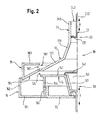
- FIG. 1 shows a schematic representation of a section through the coffee machine according to the invention. It is characterized in that on a vertical axis of rotation a, a centrifuging chamber 10 as a brewing chamber, a grinder 20 and a pump 30 are arranged coaxially one above the other.
- the centrifuging chamber 10 is composed of a frusto-conical chamber upper part 12 and a disk-shaped chamber lower part 14.
- the chamber upper part 12 is formed as a double truncated cone and comprises an upper steeper cone portion 121 and a lower shallower cone portion 122.
- the chamber base 14 is formed substantially disc-shaped.
- the annular surface 141 and the flatter cone portion 122 converge in a radially outward direction away from the axis a to a filtering or centrifuging gap 123 extending circumferentially on both of them in an outer periphery of the annular surface 141 and the flat cone portion 122. It can be designed and take on the same function as the filter gap and the annular gap according to the DE 33 28 396 C2 of the applicant.
- the annular surface 141 merges in its opposite region close to the axis into a downwardly tapered cone 301, which in the illustrated position projects into the water bowl 32 with its lower third.
- a perforated disc 302 connects radially to the cone 301. It contains several breakthroughs 303 that are water-passable.
- the hole shell 302, the cone 301 and the lid 142 include a space 143.
- the lid 142 rests with its outer edge on the annular surface 141, but can happen water in the radial direction. He has thus largely the same function as the insert 340 with the annular gap 342 according to the DE 33 28 396 ,
- the cone 301 projects into the water bowl 32 with its lower third. He thus represents an essential part of the pump 30, which operates on the principle of the centrifugal pump. So that the cone 301 can supply enough water, the water bowl 32 can be displaced in the vertical direction along the axis a.
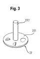
- the grinder 20 connects. It comprises a fixed grinding tool 22, the principle of which in FIG. 3 is shown enlarged.
- the grinding tool 22 thus consists of a radial Rasperface 221, which is attached to an axial stem 222.
- the grinding tool 22 is surrounded by a cylindrical grinder container 24, whose vertical lateral surface 241 merges at its lower end into the steeper cone portion 121 of the centrifuging chamber 10.
- the grinder container 24 can be loaded via a filling opening 242 with coffee beans.
- the annular collecting container 18 connects. Its inner radius corresponds to the outer radius of the centrifuging chamber 10. On its inner side 181 facing it, it has a ring-shaped and slot-shaped collecting opening 182, with which the gap 123 is aligned. On the vertical inner side 181, a horizontal annular cover 183 adjoins the upper side radially, with an inclined bottom 184 lying opposite to it. Its inclination corresponds to that of the flatter cone portion 122.
- the outer wall 162 is so far up that the collecting container 18 partially in the Dust container 16 immersed in the upper area.
- the annular inner wall 163 is aligned with the annular wall 144 of the lower chamber part 14, which projects downwardly from the annular surface 141 in its outer region.
- FIG. 1 shows the grinding and brewing position of the coffee machine according to the invention.
- the coffee machine After filling the grinder container 24 through its filling opening 42 with coffee beans, the coffee machine can be put into operation.
- An unillustrated motor drives the grinder 20 and that the grinder container 24 and puts it into rotation.
- the fixed grinding tool 22 grates the coffee beans in the rotating grinder container 24 and mills them.
- the resulting coffee powder falls by gravity vertically downwards into the centrifuging chamber 10. There it first passes into the steeper cone portion 121 and finally into the flatter cone portion 122. At the latest, when it comes up on the chamber base 14, the rotation of the centrifuging chamber 10 drives the coffee powder radially outward.
- the upper chamber part 12 Since the grinder container 24 in The chamber upper part 12 rotates in one piece, the upper chamber part 12 at the same angular velocity as the grinder 20.
- the upper chamber part 12 is in the region of the gap 123 in a frictional connection to the lower chamber part 14, so that this is driven at the same angular velocity and rotated.
- the centrifugal force pushes the water in the centrifugal chamber 10 at its outer edge and thus through the coffee powder. After elution of the coffee powder, the centrifugal force pushes the brewed beverage through the centrifuging gap 123 so that it sprays into the collecting container 18. Due to the inclined bottom surface 184 it collects at an outer edge of the collection container 18, from where it can drain into a provided cup.
- the grinder 20 Since only the required amount of coffee beans and water in the grinder 20 and in the pump 30 are passed, the grinder 20 does not need to be switched off after completion of the grinding process, whereby a coupling and its actuator can be omitted.
- the pump 30 does not need to be separately activated or deactivated, but runs along with it and is merely put into action by adding brewing water into the water bowl 32. If the metered for the desired beverage water is used up, the pump 30 does not need to be disabled and thus operated separately. It runs as long as empty until the brewing water has passed the centrifuging 10 completely and the drink is ready made. Therefore, no additional switching and coupling devices are required for them.
- the centrifuging chamber 10 is moved vertically downward, as in FIG. 2 shown. Once the flat cone portion 122 and the bottom surface 184 of the collection container 18 are aligned with each other, the centrifuging chamber 10 can be opened. For this, the lower chamber part 14 is lowered further. As a result, the centrifuging gap 123 ( FIG. 1 ) to a larger opening gap 124, so that it can happen to coffee trester.
- the water bowl 32 can be moved down. In a fully lowered position of the chamber lower part 14, the cone 301 then sits on the bottom of the water bowl 32.
- the vertical mobility of the otherwise rotationally fixed water bowl serves to supply less water to the water bowl 32 in a preparation process.
- the water bowl 32 can rather be traced to the lower chamber part 14 or the cone 301, so that it can dive as deeply as possible into the water bowl 32.
- the chamber upper part 12 and the immediately adjacent jacket 241 of the grinder are set in a motor by rotation. In addition, they can be moved vertically by a smaller displacement.
- the lower chamber part 14 with the cone 301 connected thereto are not driven directly by the motor, but by the frictional engagement in the region of the centrifuging gap 123 and thus indirectly via the upper chamber part 12. However, they can be moved vertically over a larger displacement path f move vertically so that the gap 123 can be opened after a shift of the upper chamber part 12 in the direction e for ejecting the pomace in the pulp container 16.
- the compact design of the described coffee machine means that a transmission for driving the grinder, the pump or the centrifuging can be omitted. All components, ie the centrifuging chamber 10, the grinder 20 and the pump 30 can be driven by one and the same motor. Couplings between them and the engine and their controls can also be omitted. In addition, no elaborate fluid system possibly with a ceramic multiple valve is required, which further simplifies the structure. Overall, results in an extremely simple and compact design, which can be expected low production costs.
- the preceding grinder, pump and centrifuging chamber of a fully automatic coffee machine described in detail are one embodiment, they can be modified in a customary manner by a person skilled in the art to a large extent, without departing from the scope of the invention.
- the concrete configurations of the grinding tool can also follow in a different form than described here.
- the residue container and the collecting container can be configured in another form, if this is necessary for reasons of space or designerischen reasons.
- the use of the indefinite article "on" does not preclude that the features in question may also be duplicated.
Abstract
Ein Kaffeevollautomat für Haushaltszwecke mit einer Zentrifugierkammer (10) mit einem Kammeroberteil (12) und einem ihm gegenüber bewegbaren Kammerunterteil (14) als Brühraum, mit einem Motor zum Antreiben der Zentrifugierkammer (10), mit einem Mahlwerk (20), das koaxial zur Zentrifugierkammer (10) und über ihr angeordnet ist und vom Motor antreibar ist, wird durch eine starre Kopplung zwischen dem Kammeroberteil (12) und dem Mahlwerk (20) weitergebildet.A coffee machine for domestic use comprising a centrifuging chamber (10) having a chamber top (12) and a chamber bottom part (14) movable opposite it as a brewing chamber, with a motor for driving the centrifuging chamber (10), with a grinder (20) coaxial with the centrifuging chamber (10) and is arranged above it and is driven by the motor, is further developed by a rigid coupling between the chamber upper part (12) and the grinder (20).
Description
Die Erfindung betrifft einen Kaffeevollautomaten für Haushaltszwecke mit einer Zentrifugierkammer mit einem Oberteil und einem ihm gegenüber axial bewegbaren Unterteil als Brühraum, wobei eine Bewegung des Oberteils gegenüber dem Unterteil einen vergrößerbaren Spalt zwischen beiden ausbildet, mit einem Motor zum Antreiben der Zentrifugierkammer und mit einem Mahlwerk, das koaxial zur Zentrifugierkammer und über ihr angeordnet ist und ebenfalls vom Motor antreibbar ist.The invention relates to a coffee machine for domestic use with a centrifuging chamber with an upper part and an axially movable lower part as a brewing chamber, wherein a movement of the upper part relative to the lower part forms an enlargeable gap between the two, with a motor for driving the centrifuging and a grinder, which is arranged coaxially to the centrifuging and above it and is also driven by the motor.
Die
Aufgabe der Erfindung ist es, einen Kaffeevollautomat für Haushaltszwecke anzugeben, der ebenfalls Zentrifugalkräfte zur Kaffeebereitung nutzt, dessen Aufbau jedoch einfacher ist.The object of the invention is to provide a coffee machine for household purposes, which also uses centrifugal forces for coffee making, but whose structure is simpler.
Diese Aufgabe wird bei einem eingangs genannten Kaffeevollautomaten erfindungsgemäß dadurch gelöst, dass zwischen dem Kammeroberteil und dem Mahlwerk eine unmittelbare rotatorische Kopplung besteht. Die Kopplung stellt folglich einen Kraftschluss zwischen dem Kammeroberteil und dem Mahlwerk ohne Zwischenschaltung eines Getriebes oder dergleichen her. Das Mahlwerk ist vorteihafterweise oberhalb der Zentrifugierkammer angeordnet, damit das Mahlgut allein aufgrund der Schwerkraft in die Zentrifugierkammer gelangen kann. Daher kann die Kopplung zwischen dem Mahlwerk und der Zentrifugierkammer an deren Kammeroberteil angreifen. Bei aktivierter Kopplung kann der Motor das Kammeroberteil und das Mahlwerk in derselben Winkelgeschwindigkeit antreiben. Die Erfindung ermöglicht damit also den Wegfall eines separaten Antriebs oder eines Getriebestrangs entweder für die Zentrifugierkammer oder für das Mahlwerk. Sie verfolgt vielmehr das Prinzip, die Zentrifugierkammer bzw. das Kammeroberteil und das Mahlwerk nicht nur mit Hilfe desselben Motors anzutreiben, sondern beide mit derselben Geschwindigkeit zu betreiben. Dadurch können ein aufwändiger Antrieb und ein entsprechendes Getriebe für eine der beiden Bestandteile des Kaffeevollautomaten entfallen, also entweder für das Mahlwerk oder für die Zentrifugierkammer. Sobald also beispielsweise das Kammeroberteil durch den Motor angetrieben wird und die Kopplung zwischen dem Kammeroberteil einerseits und dem Mahlwerk andererseits aktiv ist, ist zugleich auch das Mahlwerk in Betrieb genommen. Mit einer deaktivierbaren Kopplung lässt sich ggf. nur eines der beiden Bestandteile, also entweder die Zentrifugierkammer oder das Mahlwerk, separat betreiben, ohne dass der andere Bestandteil angetrieben wird. Eine dauerhafte Kopplung zwischen dem Kammeroberteil und dem Mahlwerk dagegen begünstigt einen besonders einfachen Aufbau des Kaffeevollautomaten, weil sowohl die Kopplung selbst als auch ihre Betätigungs- und Steuerungsvorrichtung entfallen können.This object is achieved according to the invention in a coffee machine mentioned above in that there is an immediate rotational coupling between the upper chamber part and the grinder. The coupling thus produces a frictional connection between the upper chamber part and the grinder without the interposition of a transmission or the like. The grinder is vorteihafterweise arranged above the centrifuging, so that the material to be ground can get into the centrifuging alone due to gravity. Therefore, the coupling between the grinder and the Zentrifugierkammer at the Attack the upper part of the chamber. When coupling is enabled, the motor can drive the chamber top and grinder at the same angular velocity. Thus, the invention thus allows the elimination of a separate drive or a gear train either for the centrifuging or for the grinder. Rather, it pursues the principle of not only driving the centrifuging chamber or the chamber upper part and the grinding mechanism with the aid of the same motor, but also operating both at the same speed. As a result, a complex drive and a corresponding transmission for one of the two components of the coffee machine omitted, so either for the grinder or for Zentrifugierkammer. As soon as, for example, the upper chamber part is driven by the motor and the coupling between the upper chamber part on the one hand and the grinder on the other hand is active, at the same time the grinder is put into operation. With a deactivatable coupling, if necessary, only one of the two components, ie either the centrifuging chamber or the grinder, can be operated separately, without the other component being driven. A permanent coupling between the upper chamber part and the grinder on the other hand favors a particularly simple construction of the coffee machine because both the coupling itself and its actuating and control device can be omitted.
Bekannte Mahlwerke umfassen regelmäßig ein feststehendes Mahlwerksgehäuse, das eine Mahlkammer bildet und in dem das Mahlgut aufgenommen wird, und ein angetriebenes Mahlwerkzeug, um das Mahlgut zu zerkleinern. Nach einer vorteilhaften Ausgestaltung der Erfindung umfasst der Kaffeevollautomat demgegenüber ein Mahlwerk mit einem feststehenden Mahlwerkzeug und einem antreibbaren Mahlwerksbehälter. Erfindungsgemäß erfolgt also eine kinematische Umkehr des Mahlwerksaufbaus bezüglich des Mahlwerksbehälters einerseits und des Mahlwerkzeugs andererseits. Durch den erfindungsgemäßen Antrieb des Mahlwerksbehälters und das feststehende Mahlwerkzeug lässt sich insbesondere eine dauerhafte Kopplung zwischen dem Kammeroberteil und dem Mahlwerk konstruktiv einfach und damit kostengünstig herstellen. Das Kammeroberteil und der Mahlwerksbehälter können beispielsweise über einen gemeinsamen Mantel verfügen und durch einen radialen Zwischenboden voneinander getrennt sein. Damit kann insbesondere eine Antriebsachse für das Mahlwerk entfallen, die die Zentrifugierkammer durchdringt und ihr gegenüber regelmäßig gelagert und abgedichtet sein muss. Nicht zuletzt dadurch kann der Kaffeevollautomat einen wesentlich kompakteren Aufbau erhalten. Als Mahlwerksprinzip eignen sich so gut wie alle bekannten Prinzipien, beispielsweise Schlag-, Kegel-, Walzen-, Scheiben- oder Raspelmahlwerke. Oberhalb des Mahlwerks kann ein Bohnenbehälter angeordnet sein, von dem aus eine Tassenportion an Bohnen in das Mahlwerk abgegeben werden kann.Known grinders regularly comprise a fixed grinder housing, which forms a grinding chamber and in which the material to be ground is received, and a driven grinding tool to comminute the material to be ground. According to an advantageous embodiment of the invention, the coffee machine on the other hand comprises a grinder with a fixed grinding tool and a driven grinder container. According to the invention, therefore, a kinematic reversal of the grinder assembly with respect to the grinder container on the one hand and the grinding tool on the other hand. Due to the drive according to the invention of the grinding container and the fixed grinding tool, in particular, a permanent coupling between the chamber upper part and the grinding mechanism can be produced in a structurally simple and hence cost-effective manner. The chamber upper part and the grinder container may, for example, have a common jacket and be separated from each other by a radial intermediate bottom. Thus, in particular a drive axle for the grinder can be omitted, which penetrates the Zentrifugierkammer and her regularly stored and sealed. Not least because of this, the coffee machine can get a much more compact design. As a grinder principle are as well as all known principles, such as impact, cone, roller, disc or Raspelmahlwerke. Above the grinder, a bean container may be arranged, from which a cup portion of beans can be discharged into the grinder.
Bei vielen bekannten Kaffeezubereitungsgeräten, die Zentrifugalkräfte nutzen, muss das Wasser separat, zum Beispiel von Hand, zugegeben werden. Nach einer vorteilhaften Ausgestaltung der Erfindung kann der Kaffeevollautomat eine unterhalb der Zentrifugierkammer angeordnete Wasservorratsschale und eine Pumpe zur Wasserförderung von Zubereitungswasser aus der Wasservorratsschale in die Zentrifugierkammer umfassen. Die Wasservorratsschale kann koaxial zur Zentrifugierkammer angeordnet sein, um dem Kaffeevollautomaten einen weitgehend symmetrischen Aufbau zu verleihen. Alternativ können die Pumpe und die Wasserschale aus Platzgründen nebeneinander angeordnet sein, solange die Förderung von Wasser aus der Wasserschale in die Zentrifugierkammer gewährleistet ist. Die Wasservorratsschale enthält einen Wasservorrat für mindestens eine Getränkeportion und kann vorteilhafterweise zugleich eine Heizeinrichtung umfassen, mit der das Vorratswasser auf Brühtemperatur gebracht werden kann, bevor die Pumpe es in die Zentrifugierkammer fördert. Eine größere Wasservorratsschale kann das Wasser für mehr als nur eine Getränkeportion aufnehmen und damit ein häufigeres Nachfüllen erübrigen.In many known coffee makers that use centrifugal forces, the water must be added separately, for example by hand. According to an advantageous embodiment of the invention, the coffee machine can comprise a arranged below the centrifuging water reservoir and a pump for conveying water from the preparation water from the water reservoir into the centrifuging. The water reservoir can be arranged coaxially to the centrifuging chamber to give the coffee machine a largely symmetrical structure. Alternatively, the pump and the water bowl can be arranged side by side for reasons of space, as long as the delivery of water from the water bowl is ensured in the centrifuging. The water reservoir contains a supply of water for at least one portion of beverage and may advantageously at the same time comprise a heating device with which the supply water can be brought to brewing temperature before the pump delivers it to the centrifuging. A larger reservoir of water can hold the water for more than just a portion of drinks, thus eliminating the need for frequent refills.
Auch die Pumpe benötigt eine Energiezufuhr bzw. einen Antrieb, um das Wasser zu fördern. Sie kann vorteilhafterweise ebenfalls vom Motor antreibbar sein, der die Zentrifugierkammer und das Mahlwerk betätigt. Vorteilhafterweise kann eine Pumpe vorgesehen sein, deren Antrieb ebenfalls durch eine Kopplung mit der Zentrifugalkammer erfolgen kann, insbesondere mit deren Kammerunterteil. Bei aktivierter Kopplung und angetriebener Zentrifugierkammer wird folglich auch die Pumpe aktiviert und fördert Wasser aus der Wasserschale in die Zentrifugierkammer. Um die Pumpe zu deaktivieren, braucht lediglich die Kopplung deaktiviert zu werden. Damit entfällt wiederum ein aufwändiger Getriebestrang zum separaten Antreiben der Pumpe, was den Aufbau und damit die Herstellungskosten des Kaffeevollautomaten reduziert. Eine aktivierbare Kopplung zwischen der Pumpe und der Zentrifugierkammer kann deren unabhängigen Betrieb von der Pumpe ermöglichen. Im Betrieb der Pumpe gelangt das Zubereitungswasser aus der Wasserschale über das Kammerunterteil in die Zentrifugierkammer. Alternativ kann die Pumpe starr mit der Zentrifugierkammer gekoppelt sein, so dass die Pumpe immer dann aktiviert ist, wenn die Zentrifugierkammer angetrieben ist. Dadurch kann eine Betätigung einer Kupplungseinrichtung zur Kopplung der Pumpe an die Zentrifugierkammer entfallen. Dies kann wiederum zu einer Reduktion des mechanischen bzw. konstruktiven Aufwands der Kaffeemaschine führen.Also, the pump requires a power supply or a drive to promote the water. It can advantageously also be driven by the motor, which actuates the centrifuging chamber and the grinder. Advantageously, a pump may be provided, the drive can also be done by a coupling with the centrifugal chamber, in particular with the lower chamber part. With activated coupling and driven centrifuging consequently the pump is activated and promotes water from the water bowl into the centrifuging. To deactivate the pump, only the coupling needs to be deactivated. This eliminates again a complex gear train for separately driving the pump, which reduces the structure and thus the manufacturing cost of the coffee machine. An activatable coupling between the pump and the centrifuging chamber may allow its independent operation by the pump. During operation of the pump, the preparation water from the water bowl passes through the lower chamber part into the centrifuging chamber. Alternatively, the pump may be rigidly coupled to the centrifuging chamber so that the pump is always activated when the centrifuging chamber is driven. As a result, an actuation of a coupling device for coupling the pump to the centrifuging chamber can be dispensed with. This can turn to lead to a reduction of the mechanical or constructive effort of the coffee machine.
Nach einer vorteilhaften Ausgestaltung der Erfindung kann die Pumpe als Kreiselpumpe ausgebildet sein, die durch Kopplung an die Zentrifugierkammer vom Motor antreibbar ist. In einer konstruktiv einfachen Ausführungsform kann sie ausgebildet sein wie in der
Bei einer starren Kopplung sowohl des Mahlwerks als auch der Kreiselpumpe an die Zentrifugierkammer ist die Pumpe bereits zeitgleich mit dem Mahlwerk aktiviert. Durch eine rechtzeitige Zugabe des Zubereitungswassers in den Saugbereich der Pumpe kann dafür gesorgt werden, dass es erst dann in die Zentrifugierkammer gelangt, wenn jene bereits mit Kaffeepulver gefüllt ist. Nach einer vorteilhaften Ausgestaltung der Erfindung kann der Kaffeevollautomat über einen separaten Wasservorratsbehälter oberhalb der Wasserschale und eine verschließbare Leitungsverbindung dorthin verfügen. Der Wasservorratsbehälter kann ein Volumen an Zubereitungswasser vorzugsweise für mehrere Getränkeportionen umfassen. Weil er über die verschließbare Leitungsverbindung an die Wasserschale gekoppelt ist, kann eine Teilmenge entsprechend einer Getränkeportion in die Wasserschale abgegeben werden. Die Leitungsverbindung kann beispielsweise über ein hand- oder elektrisch betätigtes Ventil verfügen, das zum geeigneten Zeitpunkt während der Zubereitung des Brühgetränks, beispielsweise für eine bestimmte Zeitdauer, geöffnet wird. Auf diese Weise kann zwar die Kreiselpumpe gleichzeitig mit dem Mahlwerk aktiviert werden. Mangels Wasser in der Wasserschale allerdings gelangt kein Wasser in die Zentrifugierkammer, bevor sie nicht mit der gewünschten Menge an Kaffeepulver gefüllt ist. Erst dann kann die Leitungsverbindung zwischen dem Wasservorratsbehälter und der Wasserschale gezielt oder gesteuert geöffnet werden, um Zubereitungswasser in die Wasserschale gelangen zu lassen. Da die Pumpe bei sich drehender Zentrifugierkammer ebenfalls in Betrieb ist, wird das Wasser unmittelbar aus der Wasserschale in die Zentrifugierkammer geleitet. Damit braucht nicht die Pumpe separat angesteuert zu werden, sondern lediglich die Wasserzufuhr, wofür ein geringerer technischer Aufwand erforderlich ist. Zwischen dem Wasservorratsbehälter und der Wasserschale kann eine Heizeinrichtung angeordnet sein, die das Wasser auf Brühtemperatur bringt. Statt eines separaten Wasservorratsbehälters kann der erfindungsgemäße Kaffeevollautomat alternativ an ein Haushaltswassernetz angeschlossen sein.In a rigid coupling of both the grinder and the centrifugal pump to the centrifuging the pump is already activated simultaneously with the grinder. By a timely addition of the preparation water in the suction of the pump can be taken to ensure that it only enters the centrifuging when that is already filled with coffee powder. According to an advantageous embodiment of the invention, the coffee machine can have a separate water reservoir above the water bowl and a closable line connection there. The water reservoir may preferably comprise a volume of cooking water for a plurality of beverage portions. Because it is coupled via the closable line connection to the water bowl, a partial amount corresponding to a beverage portion can be dispensed into the water bowl. The line connection may, for example, have a manually or electrically actuated valve which is opened at the appropriate time during the preparation of the brewing beverage, for example for a certain period of time. In this way, although the centrifugal pump can be activated simultaneously with the grinder. However, in the absence of water in the water bowl, no water enters the centrifugation chamber until it is filled with the desired amount of coffee powder. Only then can the line connection between the water storage tank and the water bowl be opened in a targeted or controlled manner to allow water of preparation to enter the water bowl. Since the pump is also in operation with rotating centrifuging, the water is passed directly from the water bowl in the centrifuging. Thus, the pump does not need to be controlled separately, but only the water supply, for which a lesser technical effort is required. Between the water reservoir and the water bowl, a heater may be arranged, the water to brewing temperature brings. Instead of a separate water reservoir, the coffee machine according to the invention can alternatively be connected to a domestic water network.
Nach Ausgabe des gebrühten Kaffeegetränks kann die Zentrifugalkraft zur Selbstreinigung der Zentrifugalkammer genutzt werden. Dazu kann die Zentrifugierkammer aus einem kegelförmigen Kammeroberteil und einem scheibenförmigen Kammerunterteil aufgebaut sein, die gegeneinander in axialer Richtung verfahrbar sind. Nach Abschluss des Brühverfahrens können das Kammeroberteil und das Kammerunterteil auseinander gefahren werden, so dass zwischen ihnen ein größerer Spalt entsteht. Die Zentrifugalkraft bewirkt nun, dass der ausgelaugte Kaffeetrester von dem scheibenförmigen Kammerunterteil in radialer Richtung abgeschleudert wird. Auf Kaffeetrester, der am Kammeroberteil haftet, wirkt die Zentrifugalkraft ebenfalls, die ihn durch den entstehenden Spalt radial nach außen befördert. Vorteilhafterweise besteht zwischen dem Kammeroberteil und dem Kammerunterteil eine Reibschlusskupplung, so dass bei Anlage der beiden Teile aneinander das nicht angetriebene Kammerteil der Zentrifugierkammer über den Reibschluss am anderen Kammerteil ebenfalls angetrieben wird. Vorzugsweise besteht die Reibschlusskupplung umfangsseitig zwischen dem Kammeroberteil und dem Kammerunterteil, weil sie dort ohnehin aneinander anliegen, wenn sie gemeinsam die Zentrifugierkammer zur Zubereitung eines Kaffeegetränks bilden. Das Auseinanderfahren beider Kammerteile kann vorzugsweise gegen die Kraft einer axial wirkenden Feder erfolgen, so dass die aktivierte Reibschlusskupplung unter Federvorspannung steht.After dispensing the brewed coffee beverage, the centrifugal force can be used for self-cleaning of the centrifugal chamber. For this purpose, the centrifuging chamber can be constructed from a conical chamber upper part and a disk-shaped chamber lower part, which can be moved in the axial direction relative to one another. After completion of the brewing process, the chamber upper part and the lower chamber part can be moved apart so that a larger gap is created between them. The centrifugal force now causes the leached coffee residue is thrown off the disc-shaped chamber base in the radial direction. On coffee residue, which adheres to the upper chamber part, the centrifugal force also acts, which carries him through the resulting gap radially outwards. Advantageously, there is a frictionally engaging coupling between the upper chamber part and the lower chamber part, so that when the two parts bear against each other, the non-driven chamber part of the centrifuging chamber is likewise driven via the frictional connection on the other chamber part. Preferably, the frictional coupling is circumferentially between the upper chamber part and the lower chamber part because they abut each other there anyway, if they together form the centrifuging chamber for preparing a coffee beverage. The moving apart of the two chamber parts can preferably take place against the force of an axially acting spring, so that the activated friction clutch is spring-loaded.
Nach einer weiteren vorteilhaften Ausgestaltung der Erfindung umfasst der Kaffeevollautomat einen Tresterbehälter, der ringförmig und koaxial zur Zentrifugierkammer und konzentrisch zur Wasserschale angeordnet ist. Dadurch lässt sich eine kompakte Anordnung der Wasserschale einerseits und des Tresterbehälters andererseits erreichen. Die Wasserschale kann den Bereich unterhalb des Kammerunterteils einnehmen, wohin ohnehin kein Trester abgegeben werden kann. Da der Trester die Zentrifugierkammer der Zentrifugalkraft folgend radial verlässt, sollte der Tresterbehälter jedenfalls einen größeren Außenradius aufweisen als sie.According to a further advantageous embodiment of the invention, the coffee machine comprises a pulp container, which is arranged annularly and coaxially to the centrifuging and concentric with the water bowl. This makes it possible to achieve a compact arrangement of the water bowl on the one hand and the pulp container on the other. The water bowl can occupy the area below the chamber base, where anyway no pomace can be delivered. In any case, since the pomace leaves the centrifuging chamber radially following the centrifugal force, the pomace container should have a larger outer radius than it does.
Nach einer weiteren vorteilhaften Ausgestaltung der Erfindung umfasst der Kaffeevollautomat einen Auffangbehälter für das Brühgetränk, der ringförmig und koaxial zur Wasserschale und zum Tresterbehälter angeordnet ist. Anders als der Trester verlässt das Brühgetränk die Zentrifugierkammer, solange sie noch weitgehend geschlossen ist, durch einen engen Filter- oder Zentrifugierspalt, den das Kammeroberteil und das Kammerunterteil an ihrem Umfang zwischen sich bilden. Zum Öffnen des Zentrifugierspalts beim Tresterentleeren können das Kammeroberteil und das Kammerunterteil auseinander gefahren werden, um einen größeren Spalt zwischen sich zu bilden. Wird dazu nur das Kammeroberteil angehoben, so findet die Getränkeausgabe weitgehend auf dem gleichen Niveau statt wie das Ausschleudern des Tresters. Daher kann der Tresterbehälter beim Auseinanderfahren der Zentrifugierkammer ebenfalls angehoben werden. Vorteilhafterweise kann daher das Kammerunterteil abgesenkt werden. Damit ergibt sich ein unterschiedliches Ausgabeniveau zwischen dem Getränk, nämlich durch den Zentrifugierspalt, einerseits, und dem Trester, nämlich bei geöffneter Zentrifugierkammer und abgesenktem Kammerunterteil, andererseits. Das Ausgabeniveau des Tresters liegt tiefer, so dass der Auffangbehälter einerseits und der Tresterbehälter andererseits lediglich in unterschiedlichen Höhen angebracht werden müssen, um das Getränk nicht durch die Tresterausgabe zu beeinträchtigen. Vorteilhafterweise kann zusätzlich auch das Kammeroberteil geringfügig abgesenkt werden. Zusätzlich kann eine Unterseite des Auffangbehälters für das Kaffeegetränk als Trennfläche die Neigung des Kammeroberteils radial nach außen fortsetzen, so dass abgeschleuderter Trester vom Kammerunterteil gegen die Schrägfläche gelangt und von dort abwärts in den Tresterbehälter fällt. Dadurch ergibt sich insgesamt ein sehr kompakter Aufbau des Kaffeevollautomaten, weil Getriebe, separate Antriebe und Steuerungen für die einzelnen Bestandteile wie Mahlwerk, Zentrifugierkammer und Pumpe entfallen können und sich auch weitere, insbesondere mechanische Steuerungseinrichtungen, beispielsweise Mehrfachventile, ebenfalls erübrigen.According to a further advantageous embodiment of the invention, the coffee machine comprises a collecting container for the brewing beverage, which is arranged in a ring and coaxial with the water bowl and the pomace container. Unlike the pomace leaves the brewed drink the Zentrifugierkammer, as long as it is still largely closed, through a narrow filter or Zentrifugierspalt which form the upper chamber part and the lower chamber part at its periphery between them. To open the Zentrifugierspalts pomace emptying the chamber upper part and the lower chamber part can be moved apart to form a larger gap between them. If only the upper part of the chamber is raised for this purpose, the beverage output will largely be at the same level as the purging of the pomace. Therefore, the pulp container can also be raised when moving apart of the centrifuging. Advantageously, therefore, the lower chamber part can be lowered. This results in a different level of expenditure between the drink, namely by the Zentrifugierspalt, on the one hand, and the pomace, namely with open centrifuging and lowered chamber base, on the other. The level of expenditure of the pomace is lower, so that the container on the one hand and the pomace container on the other hand only need to be mounted at different heights, so as not to affect the drink by the pomace issue. Advantageously, in addition, the chamber upper part can also be lowered slightly. In addition, an underside of the collecting container for the coffee beverage as a separating surface continue the inclination of the upper chamber part radially outward, so that thrown-off pomace from the lower chamber part passes against the inclined surface and falls down from there into the residue container. This results overall in a very compact design of the coffee machine, because transmission, separate drives and controls for the individual components such as grinder, centrifuging and pump can be omitted and also other, in particular mechanical control devices, such as multiple valves, also unnecessary.
Das Prinzip der Erfindung wird im Folgenden anhand einer Zeichnung beispielshalber noch näher erläutert. In der Zeichnung zeigen:
- Figur 1:
- Eine Prinzipdarstellung der Erfindung in einer ersten Schnittansicht während eines Brühvorgangs,
- Figur 2:
- die Schnittansicht während des Tresterausstoßens, und
- Figur 3:
- das Mahlwerkzeug.
- FIG. 1:
- A schematic diagram of the invention in a first sectional view during a brewing process,
- FIG. 2:
- the sectional view during the pomace ejection, and
- FIG. 3:
- the grinding tool.
Die Ringfläche 141 und der flachere Kegelabschnitt 122 konvergieren in einer radialen, nach außen weisenden Richtung von der Achse a weg zu einem Filter- oder Zentrifugierspalt 123, der sich in einem äußeren Randbereich der Ringfläche 141 und des flachen Kegelabschnitts 122 umfangsseitig an beiden erstreckt. Er kann so ausgebildet sein und die gleiche Funktion übernehmen wie der Filterspalt und der Ringspalt gemäß der
Die Ringfläche 141 geht in ihrem gegenüberliegenden, achsnahen Bereich in einen abwärts gerichteten und sich dorthin verjüngenden Konus 301 über, der in der dargestellten Position mit seinem unteren Drittel in die Wasserschale 32 hineinragt. Dort schließt eine Lochscheibe 302 radial an den Konus 301 an. Sie enthält mehrere Durchbrüche 303, die wasserpassierbar sind. Die Lochschale 302, der Konus 301 und der Deckel 142 schließen einen Raum 143 ein. Der Deckel 142 liegt mit seinem äußeren Rand auf der Ringfläche 141 an, lässt aber Wasser in radialer Richtung passieren. Er hat damit weitgehend die gleiche Funktion wie der Einsatz 340 mit dem Ringspalt 342 gemäß der
Der Konus 301 ragt mit seinem unteren Drittel in die Wasserschale 32 hinein. Er stellt damit einen wesentlichen Bestandteil der Pumpe 30 dar, die nach dem Prinzip der Kreiselpumpe arbeitet. Damit der Konus 301 genügend Wasser fördern kann, lässt sich die Wasserschale 32 in vertikaler Richtung entlang der Achse a verschieben.The
Oberhalb an die Zentrifugierkammer 10 schließt sich das Mahlwerk 20 an. Es umfasst ein feststehendes Mahlwerkzeug 22, dessen Prinzip in
Radial außerhalb der Zentrifugierkammer 10 und in etwa auf Höhe des Spalts 123 schließt sich der ringförmige Auffangbehälter 18 an. Sein Innenradius entspricht dem Außenradius der Zentrifugierkammer 10. An seiner ihr zugewandten Innenseite 181 weist er eine ring- und schlitzförmige Auffangöffnung 182 auf, mit der der Spalt 123 fluchtet. An die vertikale Innenseite 181 schließt sich oberseitig radial ein horizontaler ringförmiger Deckel 183 an, dem ein geneigter Boden 184 gegenüberliegt. Seine Neigung entspricht derjenigen des flacheren Kegelabschnitts 122.Radially outside the centrifuging
Unter dem Auffangbehälter 18 liegt der ringförmige Tresterbehälter 16. Er hat einen weitgehend U-förmigen Querschnitt mit einem waagrechten Boden 161, einer höher aufragenden Außenwand 162 und einer niedrigeren Innenwand 163. Die Außenwand 162 steht soweit nach oben, dass der Auffangbehälter 18 teilweise in den Tresterbehälter 16 in dessen oberen Bereich eintaucht. Die ringförmige Innenwand 163 fluchtet mit der Ringwand 144 des Kammerunterteils 14, die von der Ringfläche 141 in deren äußeren Bereich nach unten absteht.It has a substantially U-shaped cross-section with a
Sobald die abgegebene Kaffeebohnenportion für ein Brühgetränk vermahlen und in die Zentrifugierkammer 10 gelangt ist, wird Wasser aus einem Vorratsbehälter oder einem Haushaltswasseranschluss in die Wasserschale 32 geleitet. Die eingeleitete Wassermenge entspricht derjenigen Zubereitungsmenge für ein gewünschtes Kaffeegetränk. Da das Kammerunterteil 14 und der daran anschließende Konus 301 der Pumpe 30 in die Wasserschale hineinreichen, versetzt der rotierende Konus 301 das Wasser in Rotation. Wasser, das innerhalb des Konus 301 und sich damit im Raum 143 befindet, steigt der Fliehkraft folgend am Konus 301 auf, strömt durch die Durchbrüche 303 hindurch und gelangt schließlich in einen oberen Bereich des Konus 301. Unterhalb des Deckels 142 und unter ihm hindurch fließt es auf die Ringfläche 141. Insofern zeigt sich die gleiche Funktion der Kreiselpumpe 30 wie der Hohlkegel 324 der
Die Fliehkraft drückt das Wasser in der Zentrifugalkammer 10 an deren äußeren Rand und damit durch das Kaffeepulver hindurch. Nach Eluieren des Kaffeepulvers drückt die Fliehkraft das gebrühte Getränk durch den Zentrifugierspalt 123 hindurch, so dass es in den Auffangbehälter 18 spritzt. Aufgrund der geneigten Bodenfläche 184 sammelt es sich an einem äußeren Rand des Auffangbehälters 18, von wo aus es in eine bereitgestellte Tasse ablaufen kann.The centrifugal force pushes the water in the
Da jeweils nur die benötigten Menge an Kaffeebohnen und Wasser in das Mahlwerk 20 bzw. in die Pumpe 30 geleitet werden, braucht das Mahlwerk 20 nach Abschluss des Mahlvorgangs nicht abgeschaltet zu werden, wodurch eine Kupplung und deren Betätigungseinrichtung entfallen kann. Ebenso braucht die Pumpe 30 nicht separat aktiviert bzw. deaktiviert zu werden, sondern läuft gleichsam mit und wird lediglich durch Zugabe von Brühwasser in die Wasserschale 32 in Aktion versetzt. Ist das für das gewünschte Getränk dosierte Wasser aufgebraucht, braucht auch die Pumpe 30 nicht deaktiviert und damit separat betätigt zu werden. Sie läuft solange leer mit, bis das Brühwasser die Zentrifugierkammer 10 vollständig passiert hat und das Getränk fertig zubereitet ist. Auch für sie sind daher keine zusätzlichen Schalt- und Kopplungsvorrichtungen erforderlich.Since only the required amount of coffee beans and water in the
Die kegelstumpfförmige Gestaltung der Zentrifugierkammer 10, die gegenüber der Zentrifugierkammer der
Auch die Wasserschale 32 lässt sich abwärts bewegen. In einer vollständig abgesenkten Position des Kammerunterteils 14 setzt dann der Konus 301 auf dem Boden der Wasserschale 32 auf. Die vertikale Bewegbarkeit der ansonsten rotatorisch feststehenden Wasserschale dient dazu, bei einem Zubereitungsvorgang weniger Wasser der Wasserschale 32 zuführen zu müssen. Die Wasserschale 32 kann vielmehr dem Kammerunterteil 14 bzw. dem Konus 301 nachgefahren werden, so dass er möglichst tief in die Wasserschale 32 eintauchen kann. Bei einer feststehenden Wasserschale, die in einer Position gemäß
Das Kammeroberteil 12 und der unmittelbar daran angeschlossene Mantel 241 des Mahlwerks werden motorisch in eine Rotation versetzt. Außerdem lassen sie sich um einen kleineren Verschiebeweg e vertikal verschieben. Das Kammerunterteil 14 mit dem daran angeschlossenen Konus 301 dagegen werden nicht unmittelbar motorisch angetrieben, sondern durch den Reibschluss im Bereich des Zentrifugierspalts 123 und damit mittelbar über das Kammeroberteil 12. Vertikal lassen sie sich allerdings über einen größeren Verschiebeweg f vertikal verschieben, damit der Spalt 123 nach einer Verschiebung des Kammeroberteils 12 in Richtung e zum Auswurf des Tresters in den Tresterbehälter 16 geöffnet werden kann.The chamber
Der kompakte Aufbau des beschriebenen Kaffeevollautomaten führt dazu, dass ein Getriebe zum Antrieb des Mahlwerks, der Pumpe oder der Zentrifugierkammer entfallen kann. Alle Bestandteile, also die Zentrifugierkammer 10, das Mahlwerk 20 und die Pumpe 30 können von ein- und demselben Motor angetrieben werden. Kopplungen zwischen ihnen und zum Motor sowie deren Betätigungseinrichtungen können ebenfalls entfallen. Außerdem ist kein aufwändiges Fluidsystem ggf. mit einem keramischen Mehrfachventil erforderlich, was den Aufbau weiter vereinfacht. Insgesamt ergibt sich ein extrem einfacher und kompakter Aufbau, der niedrige Herstellungskosten erwarten lässt.The compact design of the described coffee machine means that a transmission for driving the grinder, the pump or the centrifuging can be omitted. All components, ie the centrifuging
Da es sich bei den vorhergehenden, detailliert beschriebenen Mahlwerk, Pumpe und Zentrifugierkammer eines Kaffeevollautomaten um ein Ausführungsbeispiel handelt, können sie in üblicher Weise vom Fachmann in einem weiten Umfang modifiziert werden, ohne den Bereich der Erfindung zu verlassen. Insbesondere können auch die konkreten Ausgestaltungen des Mahlwerkzeugs in anderer Form als in der hier beschriebenen folgen. Ebenso können der Tresterbehälter und der Auffangbehälter in einer anderen Form ausgestaltet werden, wenn dies aus Platzgründen bzw. designerischen Gründen notwendig ist. Weiter schließt die Verwendung der unbestimmten Artikel "ein" bzw. "eine" nicht aus, dass die betreffenden Merkmale auch mehrfach vorhanden sein können.Since the preceding grinder, pump and centrifuging chamber of a fully automatic coffee machine described in detail are one embodiment, they can be modified in a customary manner by a person skilled in the art to a large extent, without departing from the scope of the invention. In particular, the concrete configurations of the grinding tool can also follow in a different form than described here. Likewise, the residue container and the collecting container can be configured in another form, if this is necessary for reasons of space or designerischen reasons. Further, the use of the indefinite article "on" does not preclude that the features in question may also be duplicated.
- 1010
- Zentrifugierkammercentrifugation
- 1212
- KammeroberteilChamber top
- 1414
- KammerunterteilChamber part
- 1616
- Tresterbehälterpulp container
- 1818
- Auffangbehälterreceptacle
- 2020
- Mahlwerkgrinder
- 2222
- Mahlwerkzeuggrinding tool
- 2424
- Mahlwerksbehältergrinder container
- 3030
- Pumpepump
- 3232
- Wasserschalewater bowl
- 121121
- steiler Kegelabschnittsteep cone section
- 122122
- flacher Kegelabschnittflat cone section
- 123123
- ZentrifugierspaltZentrifugierspalt
- 124124
- Auswurfspaltdischarge gap
- 141141
- Ringflächering surface
- 142142
- Deckelcover
- 143143
- Raumroom
- 144144
- Ringwandring wall
- 161161
- Bodenground
- 162162
- Außenwandouter wall
- 163163
- Innenwandinner wall
- 181181
- Innenseiteinside
- 182182
- Auffangöffnungcollection opening
- 183183
- Deckelcover
- 184184
- Bodenflächefloor area
- 221221
- Raspelscheiberasping
- 222222
- Stielstalk
- 241241
- Mantelcoat
- 242242
- Befüllöffnungfilling
- 301301
- Konuscone
- 302302
- Lochscheibeperforated disc
- 303303
- Durchbruchbreakthrough
- aa
- Rotationsachseaxis of rotation
- e, fe, f
- Verschiebewegdisplacement
Claims (9)
Applications Claiming Priority (1)
| Application Number | Priority Date | Filing Date | Title |
|---|---|---|---|
| DE102013210107.4A DE102013210107A1 (en) | 2013-05-29 | 2013-05-29 | Coffee machine with a centrifuging chamber |
Publications (2)
| Publication Number | Publication Date |
|---|---|
| EP2807962A1 true EP2807962A1 (en) | 2014-12-03 |
| EP2807962B1 EP2807962B1 (en) | 2017-07-12 |
Family
ID=50735986
Family Applications (1)
| Application Number | Title | Priority Date | Filing Date |
|---|---|---|---|
| EP14169397.8A Active EP2807962B1 (en) | 2013-05-29 | 2014-05-22 | Fully automatic coffee maker with a centrifuge chamber |
Country Status (2)
| Country | Link |
|---|---|
| EP (1) | EP2807962B1 (en) |
| DE (1) | DE102013210107A1 (en) |
Cited By (1)
| Publication number | Priority date | Publication date | Assignee | Title |
|---|---|---|---|---|
| WO2022048783A1 (en) * | 2020-09-07 | 2022-03-10 | Spinn Holding B.V. | Improved self-cleaning centrifugal coffee brewer |
Families Citing this family (1)
| Publication number | Priority date | Publication date | Assignee | Title |
|---|---|---|---|---|
| DE102019135389A1 (en) * | 2019-12-20 | 2021-06-24 | 10 X Innovation GmbH & Co. KG | Device for preparing a brewed beverage |
Citations (4)
| Publication number | Priority date | Publication date | Assignee | Title |
|---|---|---|---|---|
| DE2428188A1 (en) | 1973-07-09 | 1975-01-30 | Cailliot Serge | METHOD AND DEVICE FOR THE PRODUCTION OF A COFFEE I |
| DE3328396A1 (en) | 1982-08-20 | 1984-02-23 | Bosch-Siemens Hausgeräte GmbH, 7000 Stuttgart | Electrical coffee machine having a centrifugal filter |
| EP0367600A1 (en) * | 1988-11-02 | 1990-05-09 | Kabushiki Kaisha Toshiba | Centrifugal brewing type coffee maker |
| US20070079708A1 (en) * | 2005-10-11 | 2007-04-12 | Zhiping Li | Coffee maker |
-
2013
- 2013-05-29 DE DE102013210107.4A patent/DE102013210107A1/en not_active Ceased
-
2014
- 2014-05-22 EP EP14169397.8A patent/EP2807962B1/en active Active
Patent Citations (5)
| Publication number | Priority date | Publication date | Assignee | Title |
|---|---|---|---|---|
| DE2428188A1 (en) | 1973-07-09 | 1975-01-30 | Cailliot Serge | METHOD AND DEVICE FOR THE PRODUCTION OF A COFFEE I |
| DE3328396A1 (en) | 1982-08-20 | 1984-02-23 | Bosch-Siemens Hausgeräte GmbH, 7000 Stuttgart | Electrical coffee machine having a centrifugal filter |
| DE3328396C2 (en) | 1982-08-20 | 1992-04-30 | Bosch-Siemens Hausgeraete Gmbh, 8000 Muenchen, De | |
| EP0367600A1 (en) * | 1988-11-02 | 1990-05-09 | Kabushiki Kaisha Toshiba | Centrifugal brewing type coffee maker |
| US20070079708A1 (en) * | 2005-10-11 | 2007-04-12 | Zhiping Li | Coffee maker |
Cited By (1)
| Publication number | Priority date | Publication date | Assignee | Title |
|---|---|---|---|---|
| WO2022048783A1 (en) * | 2020-09-07 | 2022-03-10 | Spinn Holding B.V. | Improved self-cleaning centrifugal coffee brewer |
Also Published As
| Publication number | Publication date |
|---|---|
| EP2807962B1 (en) | 2017-07-12 |
| DE102013210107A1 (en) | 2014-12-04 |
Similar Documents
| Publication | Publication Date | Title |
|---|---|---|
| DE102005007852A1 (en) | Coffee maker in particular working with centrifugal forces, comprising lid permanently joined to drive shaft | |
| EP2119383A1 (en) | Brewing machine | |
| CH663887A5 (en) | COFFEE MACHINE WITH A CENTRIFUGAL FILTER. | |
| DE1429799B2 (en) | Coffee machine with a device to prevent sewage drops from the shower head | |
| DE3529053A1 (en) | Electric coffee machine with a centrifugal filter | |
| DE60004402T2 (en) | GROUP FOR THE PREPARATION OF INFUSION BEVERAGES AND MACHINERY WITH SUCH A GROUP | |
| EP2807962B1 (en) | Fully automatic coffee maker with a centrifuge chamber | |
| DE1135635B (en) | Machine for the production of coffee drinks | |
| EP0156206B1 (en) | Apparatus for grinding and compacting refuse | |
| DE3241606A1 (en) | Electric coffee machine with a centrifugal filter | |
| EP0773734B1 (en) | Tea filter for a coffee or tea machine | |
| EP0152370B1 (en) | Machine comprising a centrifugal drum | |
| CH622695A5 (en) | Cleaning device for a beverage-making container | |
| DE102019104976A1 (en) | Vending machine with automatic care device | |
| DE3126630A1 (en) | CENTRIFUG BASKET | |
| DE2616296A1 (en) | DEVICE FOR PREPARING BEVERAGES, IN PARTICULAR COFFEE, BY CENTRIFUGATING | |
| DE3639804A1 (en) | Juice centrifuge, in particular domestic centrifuge | |
| CH701625B1 (en) | A device for brewing coffee. | |
| DE102020119008B3 (en) | Separating device, device with such a separating device and method for separating solids from a liquid | |
| EP3415049A1 (en) | Tea machine with a pressing device and method of operating same | |
| AT515309B1 (en) | Filter for automatic coffee machines | |
| DE3152990C2 (en) | Coffee machine with a centrifugal filter | |
| DE1804218C (en) | Tea maker with a container that is open at the top in a vertical filling position | |
| DE3204255C2 (en) | Electric coffee maker with centrifugal filter | |
| EP3915447A1 (en) | Hot beverage maker with a dispensing device |
Legal Events
| Date | Code | Title | Description |
|---|---|---|---|
| PUAI | Public reference made under article 153(3) epc to a published international application that has entered the european phase |
Free format text: ORIGINAL CODE: 0009012 |
|
| 17P | Request for examination filed |
Effective date: 20140522 |
|
| AK | Designated contracting states |
Kind code of ref document: A1 Designated state(s): AL AT BE BG CH CY CZ DE DK EE ES FI FR GB GR HR HU IE IS IT LI LT LU LV MC MK MT NL NO PL PT RO RS SE SI SK SM TR |
|
| AX | Request for extension of the european patent |
Extension state: BA ME |
|
| RAP1 | Party data changed (applicant data changed or rights of an application transferred) |
Owner name: BSH HAUSGERAETE GMBH |
|
| R17P | Request for examination filed (corrected) |
Effective date: 20150603 |
|
| RBV | Designated contracting states (corrected) |
Designated state(s): AL AT BE BG CH CY CZ DE DK EE ES FI FR GB GR HR HU IE IS IT LI LT LU LV MC MK MT NL NO PL PT RO RS SE SI SK SM TR |
|
| RIC1 | Information provided on ipc code assigned before grant |
Ipc: A47J 31/22 20060101AFI20161017BHEP Ipc: A47J 31/42 20060101ALI20161017BHEP |
|
| GRAP | Despatch of communication of intention to grant a patent |
Free format text: ORIGINAL CODE: EPIDOSNIGR1 |
|
| INTG | Intention to grant announced |
Effective date: 20170125 |
|
| GRAS | Grant fee paid |
Free format text: ORIGINAL CODE: EPIDOSNIGR3 |
|
| GRAA | (expected) grant |
Free format text: ORIGINAL CODE: 0009210 |
|
| AK | Designated contracting states |
Kind code of ref document: B1 Designated state(s): AL AT BE BG CH CY CZ DE DK EE ES FI FR GB GR HR HU IE IS IT LI LT LU LV MC MK MT NL NO PL PT RO RS SE SI SK SM TR |
|
| REG | Reference to a national code |
Ref country code: GB Ref legal event code: FG4D Free format text: NOT ENGLISH |
|
| REG | Reference to a national code |
Ref country code: CH Ref legal event code: EP |
|
| REG | Reference to a national code |
Ref country code: AT Ref legal event code: REF Ref document number: 907535 Country of ref document: AT Kind code of ref document: T Effective date: 20170715 |
|
| REG | Reference to a national code |
Ref country code: IE Ref legal event code: FG4D Free format text: LANGUAGE OF EP DOCUMENT: GERMAN |
|
| REG | Reference to a national code |
Ref country code: DE Ref legal event code: R096 Ref document number: 502014004531 Country of ref document: DE |
|
| REG | Reference to a national code |
Ref country code: NL Ref legal event code: MP Effective date: 20170712 |
|
| REG | Reference to a national code |
Ref country code: LT Ref legal event code: MG4D |
|
| PG25 | Lapsed in a contracting state [announced via postgrant information from national office to epo] |
Ref country code: NL Free format text: LAPSE BECAUSE OF FAILURE TO SUBMIT A TRANSLATION OF THE DESCRIPTION OR TO PAY THE FEE WITHIN THE PRESCRIBED TIME-LIMIT Effective date: 20170712 Ref country code: HR Free format text: LAPSE BECAUSE OF FAILURE TO SUBMIT A TRANSLATION OF THE DESCRIPTION OR TO PAY THE FEE WITHIN THE PRESCRIBED TIME-LIMIT Effective date: 20170712 Ref country code: LT Free format text: LAPSE BECAUSE OF FAILURE TO SUBMIT A TRANSLATION OF THE DESCRIPTION OR TO PAY THE FEE WITHIN THE PRESCRIBED TIME-LIMIT Effective date: 20170712 Ref country code: FI Free format text: LAPSE BECAUSE OF FAILURE TO SUBMIT A TRANSLATION OF THE DESCRIPTION OR TO PAY THE FEE WITHIN THE PRESCRIBED TIME-LIMIT Effective date: 20170712 Ref country code: NO Free format text: LAPSE BECAUSE OF FAILURE TO SUBMIT A TRANSLATION OF THE DESCRIPTION OR TO PAY THE FEE WITHIN THE PRESCRIBED TIME-LIMIT Effective date: 20171012 Ref country code: SE Free format text: LAPSE BECAUSE OF FAILURE TO SUBMIT A TRANSLATION OF THE DESCRIPTION OR TO PAY THE FEE WITHIN THE PRESCRIBED TIME-LIMIT Effective date: 20170712 |
|
| PG25 | Lapsed in a contracting state [announced via postgrant information from national office to epo] |
Ref country code: PL Free format text: LAPSE BECAUSE OF FAILURE TO SUBMIT A TRANSLATION OF THE DESCRIPTION OR TO PAY THE FEE WITHIN THE PRESCRIBED TIME-LIMIT Effective date: 20170712 Ref country code: BG Free format text: LAPSE BECAUSE OF FAILURE TO SUBMIT A TRANSLATION OF THE DESCRIPTION OR TO PAY THE FEE WITHIN THE PRESCRIBED TIME-LIMIT Effective date: 20171012 Ref country code: GR Free format text: LAPSE BECAUSE OF FAILURE TO SUBMIT A TRANSLATION OF THE DESCRIPTION OR TO PAY THE FEE WITHIN THE PRESCRIBED TIME-LIMIT Effective date: 20171013 Ref country code: LV Free format text: LAPSE BECAUSE OF FAILURE TO SUBMIT A TRANSLATION OF THE DESCRIPTION OR TO PAY THE FEE WITHIN THE PRESCRIBED TIME-LIMIT Effective date: 20170712 Ref country code: IS Free format text: LAPSE BECAUSE OF FAILURE TO SUBMIT A TRANSLATION OF THE DESCRIPTION OR TO PAY THE FEE WITHIN THE PRESCRIBED TIME-LIMIT Effective date: 20171112 Ref country code: RS Free format text: LAPSE BECAUSE OF FAILURE TO SUBMIT A TRANSLATION OF THE DESCRIPTION OR TO PAY THE FEE WITHIN THE PRESCRIBED TIME-LIMIT Effective date: 20170712 Ref country code: ES Free format text: LAPSE BECAUSE OF FAILURE TO SUBMIT A TRANSLATION OF THE DESCRIPTION OR TO PAY THE FEE WITHIN THE PRESCRIBED TIME-LIMIT Effective date: 20170712 |
|
| REG | Reference to a national code |
Ref country code: DE Ref legal event code: R097 Ref document number: 502014004531 Country of ref document: DE |
|
| PG25 | Lapsed in a contracting state [announced via postgrant information from national office to epo] |
Ref country code: RO Free format text: LAPSE BECAUSE OF FAILURE TO SUBMIT A TRANSLATION OF THE DESCRIPTION OR TO PAY THE FEE WITHIN THE PRESCRIBED TIME-LIMIT Effective date: 20170712 Ref country code: CZ Free format text: LAPSE BECAUSE OF FAILURE TO SUBMIT A TRANSLATION OF THE DESCRIPTION OR TO PAY THE FEE WITHIN THE PRESCRIBED TIME-LIMIT Effective date: 20170712 Ref country code: DK Free format text: LAPSE BECAUSE OF FAILURE TO SUBMIT A TRANSLATION OF THE DESCRIPTION OR TO PAY THE FEE WITHIN THE PRESCRIBED TIME-LIMIT Effective date: 20170712 |
|
| PLBE | No opposition filed within time limit |
Free format text: ORIGINAL CODE: 0009261 |
|
| STAA | Information on the status of an ep patent application or granted ep patent |
Free format text: STATUS: NO OPPOSITION FILED WITHIN TIME LIMIT |
|
| PG25 | Lapsed in a contracting state [announced via postgrant information from national office to epo] |
Ref country code: EE Free format text: LAPSE BECAUSE OF FAILURE TO SUBMIT A TRANSLATION OF THE DESCRIPTION OR TO PAY THE FEE WITHIN THE PRESCRIBED TIME-LIMIT Effective date: 20170712 Ref country code: SK Free format text: LAPSE BECAUSE OF FAILURE TO SUBMIT A TRANSLATION OF THE DESCRIPTION OR TO PAY THE FEE WITHIN THE PRESCRIBED TIME-LIMIT Effective date: 20170712 Ref country code: SM Free format text: LAPSE BECAUSE OF FAILURE TO SUBMIT A TRANSLATION OF THE DESCRIPTION OR TO PAY THE FEE WITHIN THE PRESCRIBED TIME-LIMIT Effective date: 20170712 |
|
| 26N | No opposition filed |
Effective date: 20180413 |
|
| PG25 | Lapsed in a contracting state [announced via postgrant information from national office to epo] |
Ref country code: SI Free format text: LAPSE BECAUSE OF FAILURE TO SUBMIT A TRANSLATION OF THE DESCRIPTION OR TO PAY THE FEE WITHIN THE PRESCRIBED TIME-LIMIT Effective date: 20170712 |
|
| PG25 | Lapsed in a contracting state [announced via postgrant information from national office to epo] |
Ref country code: MT Free format text: LAPSE BECAUSE OF FAILURE TO SUBMIT A TRANSLATION OF THE DESCRIPTION OR TO PAY THE FEE WITHIN THE PRESCRIBED TIME-LIMIT Effective date: 20170712 |
|
| GBPC | Gb: european patent ceased through non-payment of renewal fee |
Effective date: 20180522 |
|
| REG | Reference to a national code |
Ref country code: BE Ref legal event code: MM Effective date: 20180531 |
|
| PG25 | Lapsed in a contracting state [announced via postgrant information from national office to epo] |
Ref country code: MC Free format text: LAPSE BECAUSE OF FAILURE TO SUBMIT A TRANSLATION OF THE DESCRIPTION OR TO PAY THE FEE WITHIN THE PRESCRIBED TIME-LIMIT Effective date: 20170712 |
|
| REG | Reference to a national code |
Ref country code: IE Ref legal event code: MM4A |
|
| PG25 | Lapsed in a contracting state [announced via postgrant information from national office to epo] |
Ref country code: LU Free format text: LAPSE BECAUSE OF NON-PAYMENT OF DUE FEES Effective date: 20180522 |
|
| PG25 | Lapsed in a contracting state [announced via postgrant information from national office to epo] |
Ref country code: GB Free format text: LAPSE BECAUSE OF NON-PAYMENT OF DUE FEES Effective date: 20180522 Ref country code: IE Free format text: LAPSE BECAUSE OF NON-PAYMENT OF DUE FEES Effective date: 20180522 Ref country code: FR Free format text: LAPSE BECAUSE OF NON-PAYMENT OF DUE FEES Effective date: 20180531 |
|
| PG25 | Lapsed in a contracting state [announced via postgrant information from national office to epo] |
Ref country code: BE Free format text: LAPSE BECAUSE OF NON-PAYMENT OF DUE FEES Effective date: 20180531 |
|
| PG25 | Lapsed in a contracting state [announced via postgrant information from national office to epo] |
Ref country code: TR Free format text: LAPSE BECAUSE OF FAILURE TO SUBMIT A TRANSLATION OF THE DESCRIPTION OR TO PAY THE FEE WITHIN THE PRESCRIBED TIME-LIMIT Effective date: 20170712 |
|
| PG25 | Lapsed in a contracting state [announced via postgrant information from national office to epo] |
Ref country code: PT Free format text: LAPSE BECAUSE OF FAILURE TO SUBMIT A TRANSLATION OF THE DESCRIPTION OR TO PAY THE FEE WITHIN THE PRESCRIBED TIME-LIMIT Effective date: 20170712 Ref country code: HU Free format text: LAPSE BECAUSE OF FAILURE TO SUBMIT A TRANSLATION OF THE DESCRIPTION OR TO PAY THE FEE WITHIN THE PRESCRIBED TIME-LIMIT; INVALID AB INITIO Effective date: 20140522 |
|
| PG25 | Lapsed in a contracting state [announced via postgrant information from national office to epo] |
Ref country code: CY Free format text: LAPSE BECAUSE OF FAILURE TO SUBMIT A TRANSLATION OF THE DESCRIPTION OR TO PAY THE FEE WITHIN THE PRESCRIBED TIME-LIMIT Effective date: 20170712 Ref country code: MK Free format text: LAPSE BECAUSE OF NON-PAYMENT OF DUE FEES Effective date: 20170712 |
|
| PG25 | Lapsed in a contracting state [announced via postgrant information from national office to epo] |
Ref country code: AL Free format text: LAPSE BECAUSE OF FAILURE TO SUBMIT A TRANSLATION OF THE DESCRIPTION OR TO PAY THE FEE WITHIN THE PRESCRIBED TIME-LIMIT Effective date: 20170712 |
|
| REG | Reference to a national code |
Ref country code: AT Ref legal event code: MM01 Ref document number: 907535 Country of ref document: AT Kind code of ref document: T Effective date: 20190522 |
|
| PG25 | Lapsed in a contracting state [announced via postgrant information from national office to epo] |
Ref country code: AT Free format text: LAPSE BECAUSE OF NON-PAYMENT OF DUE FEES Effective date: 20190522 |
|
| PGFP | Annual fee paid to national office [announced via postgrant information from national office to epo] |
Ref country code: IT Payment date: 20230531 Year of fee payment: 10 Ref country code: DE Payment date: 20230531 Year of fee payment: 10 Ref country code: CH Payment date: 20230605 Year of fee payment: 10 |