EP2807912B1 - Anbaugerät - Google Patents
Anbaugerät Download PDFInfo
- Publication number
- EP2807912B1 EP2807912B1 EP14401057.6A EP14401057A EP2807912B1 EP 2807912 B1 EP2807912 B1 EP 2807912B1 EP 14401057 A EP14401057 A EP 14401057A EP 2807912 B1 EP2807912 B1 EP 2807912B1
- Authority
- EP
- European Patent Office
- Prior art keywords
- link connection
- frame
- lower link
- point
- attachment
- Prior art date
- Legal status (The legal status is an assumption and is not a legal conclusion. Google has not performed a legal analysis and makes no representation as to the accuracy of the status listed.)
- Active
Links
Images

Classifications
-
- A—HUMAN NECESSITIES
- A01—AGRICULTURE; FORESTRY; ANIMAL HUSBANDRY; HUNTING; TRAPPING; FISHING
- A01B—SOIL WORKING IN AGRICULTURE OR FORESTRY; PARTS, DETAILS, OR ACCESSORIES OF AGRICULTURAL MACHINES OR IMPLEMENTS, IN GENERAL
- A01B59/00—Devices specially adapted for connection between animals or tractors and agricultural machines or implements
- A01B59/06—Devices specially adapted for connection between animals or tractors and agricultural machines or implements for machines mounted on tractors
- A01B59/066—Devices specially adapted for connection between animals or tractors and agricultural machines or implements for machines mounted on tractors of the type comprising at least two lower arms and one upper arm generally arranged in a triangle (e.g. three-point hitches)
Definitions
- the invention relates to an attachment according to the preamble of claim 1.
- Another attachment is in the DE 33 37 654 A1 described.
- This attachment has on its Ankuppelseite arranged on the frame three-point coupling elements for mounting on a three-point coupler with lower link arms and top link having tractor.
- the three-point coupling elements of the attachment have a top link connecting element and two lower link connecting elements for coupling to the lower link arms and the upper link.
- the lower link connecting elements with the lower link connection points are arranged in different positions by means of a sliding guide on supporting arms attached to the frame of the attachment and can be adjusted and fixed in different positions by means of adjusting devices in and against the direction of travel, so that the respective sub-connection point are brought into the respectively desired position can.
- the support arms, on which the lower link connecting elements are arranged displaceably with the lower link connection points, must absorb and / or transmit both thrust forces or tensile forces in the horizontal direction as well as lifting forces in the vertical direction. For this reason, the support arms must be made relatively stable and solid. It is also disadvantageous that in the further pushing of the lower link connecting elements on the support arms, the support arms over the lower link connecting elements survive, which is a hindrance in the Ankoppelungsvorgang the lower links to the lower link connecting points of the lower link connecting elements, especially in cramped cultivation conditions. Thus, the protruding ends of the support arms protrude far far in the space of the tractor with far deferred lower link connecting elements in a disadvantageous and obstructive manner.
- the invention has for its object to provide a simple and stable adjustable adjustment for adjustable lower link connections even in cramped conditions.
- a preferred placement of the joints for the pivot lever results from the fact that the joints for the pivot lever are located approximately at the height of the upper link connecting point.
- a good setting and force transmission between the lower link connecting elements and the frame of the attachment is achieved in that the respective adjusting device is located between the respective joint and the respective lower link connecting point, that the respective adjusting device is closer to the respective lower link connecting point than at the respective joint.
- the attachment has the frame 1.
- the attachment may be designed as a lawnmower, tillage implement, spreader, mower, hay harvester, etc.
- the upper link terminal 4 has a plurality of trained as bores 6 Oberscher connection points at which the upper link of the three-point coupler is to be connected according to the respective mounting conditions by means of a bolt.
- the lower link connecting elements 3 of the attachment are located on pivoting levers 7. At the lower ends of the pivot lever 7 are each formed as a breakthrough 8 lower link connecting point. Through the opening 8, a pin 9 is inserted to connect the respective lower link of the three-point coupler. This makes it possible to connect the respective lower link of the three-point coupler with the lower link connection point 8 in a fixable manner.
- the lower link connecting points 8 have the pivot lever 7 are fastened by means of a hinge 10 to the frame 1 of the attachment.
- this joint 10 is above the lower link connecting points 8.
- these joints are 10 for the pivot lever 7 approximately at the height of the upper link connecting point 4, as can be seen from the drawings.
- the two lower link connecting elements 8 are respectively arranged on pivoting levers 7 which are articulated on the frame 1 by means of a joint 10 located at a distance from the respective lower link connecting element 3.
- the respective adjusting device 11 is located between the respective joint 10 and the respective lower link connecting point 8. The respective adjusting device 11 is located closer to the respective lower link connecting point 8 than to the respective joint 10.
- the respective sub-connection point 8 is to be set and fixed in different positions in and against the direction of travel 15.
- the pivot lever 7 are set by the adjustment 13 in different positions and distances for the lower link connecting points 8 of the lower link connecting elements 3 to the frame 1, in which the bolts 14 of the adjusting device 13 in the respective bore of the lower link connecting point elements 3 and pivot lever 7 after the corresponding pivoting of the pivot lever 7 are inserted in the desired position.
- the lower link connection point 8 of the respective lower link connection point 3 forms, so to speak, in each case the front end of the attachment.
- the lower link connecting point elements 3 can be easily adapted to the respective mounting conditions of the three-point coupler of the tractor on which the attachment is to be installed.
Landscapes
- Life Sciences & Earth Sciences (AREA)
- Zoology (AREA)
- Engineering & Computer Science (AREA)
- Mechanical Engineering (AREA)
- Soil Sciences (AREA)
- Environmental Sciences (AREA)
- Agricultural Machines (AREA)
Description
- Die Erfindung betrifft ein Anbaugerät gemäß des Oberbegriffes des Patentanspruches 1.
- Ein derartiges Anbaugerät ist der
GB-A-2146212 - Eine weiteres Anbaugerät ist in der
DE 33 37 654 A1 beschrieben. Dieses Anbaugerät weist auf seiner Ankuppelseite an dessen Rahmen angeordnete Dreipunktkupplungselemente zum Anbau an einen einen Dreipunktkuppler mit Unterlenkerarmen und Oberlenker aufweisenden Schlepper auf. Die Dreipunktkupplungselemente des Anbaugerätes weisen ein Oberlenkeranschlusselement und zwei Unterlenkeranschlusselemente zum Ankuppeln an die Unterlenkerarme und den Oberlenker auf. Die Unterlenkeranschlusselemente mit den Unterlenkeranschlusspunkten sind mittels einer Schiebeführung auf an dem Rahmen des Anbaugerätes befestigten Tragarmen in unterschiedlichen Positionen angeordnet und können mittels Verstellvorrichtungen in und entgegen der Fahrtrichtung in unterschiedlichen Positionen einstellt und festlegt werden, so dass der jeweilige Unteranschlusspunkt in die jeweils gewünschte Position gebracht werden kann. - Die Tragarme, auf denen die Unterlenkeranschlusselemente mit den Unterlenkeranschlusspunkten verschiebbar angeordnet sind, müssen sowohl Schubkräfte oder Zugkräfte in horizontaler Richtung wie auch Hubkräfte in vertikaler Richtung aufnehmen und/oder übertragen. Aus diesem Grunde müssen die Tragarme relativ stabil und massiv ausgestaltet sein. Auch ist nachteilig, dass bei dem weiteren Aufschieben der Unterlenkeranschlusselemente auf die Tragarme, die Tragarme über die Unterlenkeranschlusselemente überstehen, welches beim Ankoppelungsvorgang der Unterlenker an die Unterlenkeranschlusspunkte der Unterlenkeranschlusselemente, insbesondere bei beengten Anbauverhältnissen hinderlich ist. So ragen die überstehenden Enden der Tragarme bei weit aufgeschobenen Unterlenkeranschlusselementen in nachteiliger und behindernder Weise weit in den Raum des Schleppers hinein.
- Der Erfindung liegt die Aufgabe zugrunde, auch bei beengten Anbauverhältnissen eine einfach und stabil ausgestaltete Verstellmöglichkeit für verstellbare Unterlenkeranschlüsse zu schaffen.
- Diese Aufgabe wird erfindungsgemäß durch die kennzeichnenden Merkmale des Anspruches 1 gelöst.
- Infolge Maßnahmen ergibt sich eine leicht aufgebaute und trotzdem stabile Ausgestaltung verstellbarer Unterlenkeranschlusselemente. Lediglich die in horizontaler Richtung wirkenden Schub- und Zugkräfte sind von der im unteren Bereich angeordneten Verstelleinrichtung aufzunehmen, während die in vertikaler Richtung wirkenden Kräfte von den nach oben ragenden Schwenkhebeln und den zugeordneten Gelenken aufgenommen werden. In jeder möglichen Position der Unterlenkeranschlusselemente sind die Unterlenkeranschlusspunkte der jeweils die am weitesten vorstehende Bereiche. Somit gibt es keine hinderlichen überstehenden Teile im Bereich der Unterlenkeranschlusspunkte, welche in den Raum des Schleppers hindert hineinragen oder den Anbau des Anbaugerätes an den Dreipunktkuppler erschweren oder behindern.
- So wird eine vorteilhafte Anordnung der Schwenkhebel für die Unterlenkeranschlusselemente erreicht.
- Eine bevorzugte Platzierung der Gelenke für die Schwenkhebel ergibt sich dadurch, dass die Gelenke für die Schwenkhebel sich etwa auf der Höhe des Oberlenkeranschlusspunktes befinden.
- Eine gute Einstellung und Krafteinleitung zwischen den Unterlenkeranschlusselementen und dem Rahmen des Anbaugerätes wird dadurch erreicht, dass die jeweilige Verstellvorrichtung sich zwischen dem jeweiligen Gelenk und dem jeweiligen Unterlenkeranschlusspunkt befindet, dass die jeweilige Verstellvorrichtung sich näher bei dem jeweiligen Unterlenkeranschlusspunkt als bei dem jeweiligen Gelenk befindet.
- Weitere Einzelheiten der Erfindung sind der Beispielsbeschreibung zu entnehmen. Die Zeichnungen zeigen
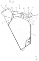
- Fig.1
- das Anbaugerät in Prinzipdarstellung und in perspektivischer Ansicht, wobei die Unterlenkeranschlusselemente mit ihren Unterlenkeranschlusspunkten in dichtstmöglicher Position zum Rahmen des Anbaugerätes eingestellt sind,
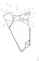
- Fig.2
- das Anbaugerät in Seitenansicht mit der Einstellung der Unterlenkeranschlusselemente mit ihren Unterlenkeranschlusspunkten gemäß
Fig. 1 und - Fig.3
- das Anbaugerät in Seitenansicht mit einer Einstellung der Unterlenkeranschlusselemente mit ihren Unterlenkeranschlusspunkten in entfernterer Stellung vom Rahmen.
- Das Anbaugerät weist den Rahmen 1 auf. Das Anbaugerät kann als Rasenmäher, Bodenbearbeitungsgerät, Verteilmaschine, Mähgerät, Heuerntemaschine, etc. ausgebildet sein. Auf der Vorderseite, die in den meisten Fällen die Ankuppelseite 2 des Anbaugerätes an einen das Anbaugerät ziehenden Schlepper ist, sind an dem Rahmen 1 des Anbaugerätes die Unterlenkeranschlusselemente 3 und der Oberlenkeranschluss 4 der Dreipunktkupplungselemente 5 zum Anbau an einen Dreipunktkuppler Unterlenkerarmen und Oberlenker aufweisenden Schlepper angeordnet.
- Der Oberlenkeranschluss 4 weist mehrere als Bohrungen 6 ausgebildete Oberlenkeranschlusspunkte auf, an denen entsprechend der jeweiligen Anbauverhältnisse mittels eines Bolzens der Oberlenker des Dreipunktkupplers anzuschließen ist.
- Die Unterlenkeranschlusselemente 3 des Anbaugerätes befinden sich an Schwenkhebeln 7. An den unteren Enden der Schwenkhebel 7 befindet sich jeweils ein als Durchbruch 8 ausgebildeter Unterlenkeranschlusspunkt. Durch den Durchbruch 8 wird zum Anschluss des jeweiligen Unterlenkers des Dreipunktkupplers ein Bolzen 9 gesteckt. Hierdurch lässt sich der jeweilige Unterlenker des Dreipunktkupplers mit dem Unterlenkeranschlusspunkt 8 in festlegbarer Weise verbinden.
- Die die Unterlenkeranschlusspunkte 8 aufweisen den Schwenkhebel 7 sind mittels eines Gelenkes 10 an dem Rahmen 1 des Anbaugerätes befestigt. Hierbei befindet sich dieses Gelenk 10 oberhalb der Unterlenkeranschlusspunkte 8. Weiterhin befinden sich diese Gelenke 10 für die Schwenkhebel 7 etwa auf der Höhe des Oberlenkeranschlusspunktes 4, wie den Zeichnungen zu entnehmen ist. Somit sind die beiden Unterlenkeranschlusselemente 8 jeweils an Schwenkhebeln 7, die an dem Rahmen 1 jeweils mittels eines beabstandet zu dem jeweiligen Unterlenkeranschlusselement 3 sich befindlichen Gelenkes 10 angelenkt sind, angeordnet. Hierbei befindet sich die jeweilige Verstellvorrichtung 11 zwischen dem jeweiligen Gelenk 10 und dem jeweiligen Unterlenkeranschlusspunkt 8. Die jeweilige Verstellvorrichtung 11 befindet sich näher bei dem jeweiligen Unterlenkeranschlusspunkt 8 als bei dem jeweiligen Gelenk 10.
- Im unteren Bereich der Schwenkhebel 7 sind an dem Rahmen 1 Verstellhalterungen 12 mit den Verstellhalterungen 12 und den unteren Enden der Schwenkhebel 7 zugeordneten Verstelleinrichtungen 13 angeordnet. Den Verstellhalterungen 12 und den Schwenkhebeln 7 sind je nach Verschwenkung der Schwenkhebel 7 um die Gelenksachse der Gelenke 10 miteinander korrespondierende Bohrungen, durch welche jeweils ein Bolzen 14 der Verstelleinrichtung 11 steckbar ist, angeordnet.
- Durch diese Anordnung sind die Schwenkhebel 7 mit den Unterlenkeranschlusspunktelementen 3 um die Gelenksachse der Gelenke 10, mit denen die Schwenkhebel 7 an dem Rahmen 1 angelenkt sind, in und entgegen der Fahrtrichtung 15 verschwenkbar und in unterschiedliche Positionen und Abständen zu dem Rahmen 1 zu bringen. Mittels 8 der zugeordneten Verstellvorrichtungen 13 ist der jeweilige Unteranschlusspunkt 8 in und entgegen der Fahrtrichtung 15 in unterschiedlichen Positionen einzustellen und festzulegen. Somit sind die Schwenkhebel 7 durch die Verstellvorrichtungen 13 in unterschiedlichen Positionen und Abständen für die Unterlenkeranschlusspunkte 8 der Unterlenkeranschlusselemente 3 zum Rahmen 1 festzulegen, in dem die Bolzen 14 der Verstellvorrichtung 13 in die jeweiligen Bohrung der Unterlenkeranschlusspunktelemente 3 und Schwenkhebel 7 nach dem entsprechenden Verschwenken der Schwenkhebel 7 in die gewünschte Position gesteckt werden.
- In den
Fig. 1 und2 sind die Schwenkhebel 7 möglichst dicht an den Rahmen 1 des Anbaugerätes herangeschwenkt und festgelegt sind, während die Schwenkhebel 7 in derFig. 3 in der weitest möglichen Position vom Rahmen 1 weggeschwenkt und in dieser Position festgelegt sind. - Wie leicht zu erkennen ist, bildet der Unterlenkeranschlusspunkt 8 des jeweiligen Unterlenkeranschlusspunktes 3 quasi jeweils das vordere Ende des Anbaugerätes. Durch das Verstellen und Festlegen der Schwenkhebel 7 mit den Unterlenkeranschlusspunktelementen 3 und -anschlusspunkten 8 lassen sich die Unterlenkeranschlusspunktelemente 3 an die jeweiligen Anbauverhältnisse des Dreipunktkupplers des Schleppers, an dem das Anbaugerät eingebaut werden soll, in einfacher Weise anpassen.
- Durch die entsprechende Ausgestaltung der feststellbaren Unterlenkeranschlusspunktelemente 3 werden die in horizontaler Richtung wirkenden wesentlichen Kräfte über die Verstellhalterungen 12 in den Rahmen 1 des Anbaugerätes eingeleitet, während die in vertikaler Richtung wirkenden Kräfte über die Gelenke 10, mit dem die Schwenkhebel 7 an dem Rahmen 1 angelenkt sind, in den Rahmen 1 eingeleitet.
Claims (3)
- Anbaugerät mit auf seiner Ankuppelseite an dessen Rahmen (1) angeordneten Dreipunktkupplungselementen (5) zum Anbau an einen einen Dreipunktkuppler mit Unterlenkerarmen und Oberlenker aufweisenden Schlepper, wobei die Dreipunktkupplungselemente (5) des Anbaugerätes ein Oberlenkeranschlusselement (4) und zwei Unterlenkeranschlusselemente (3) zum Ankuppeln an die Unterlenkerarme und den Oberlenker aufweisen, wobei den beiden Unterlenkeranschlusselementen (3) Verstellvorrichtungen (11), mittels denen der jeweilige Unteranschlusspunkt (8) in und entgegen der Fahrtrichtung (15) in unterschiedlichen Positionen einstell- und festlegbar ist, zugeordnet sind, wobei die beiden Unterlenkeranschlusselemente (3) jeweils an Schwenkhebeln (7), die an dem Rahmen (1) jeweils mittels eines beabstandet zu dem jeweiligen Unterlenkeranschlusselement (3) sich befindlichen Gelenkes (10) angelenkt sind, angeordnet sind, wobei die Schwenkhebel (7) durch die Verstellvorrichtungen (11) in unterschiedlichen Positionen und Abständen für die Unterlenkeranschlusspunkte (8) der Unterlenkeranschlusselemente (3) zum Rahmen (1) festlegbar sind, dadurch gekennzeichnet, dass die Gelenke (10) für die Schwenkhebel (7) sich oberhalb der Unterlenkeranschlusspunkte (8) befinden, dass die Schwenkhebel (7) nach oben ragend verlaufend und in und entgegen der Fahrtrichtung (15) verschwenkbar an dem Rahmen (1) angeordnet und in unterschiedlichen Positionen und Abständen zu dem Rahmen (1) festzulegen sind, dass in dem unteren Bereich der Schwenkhebel (7) am Rahmen (1) die Verstellhalterungen (12) der Verstellvorrichtungen (11) und die den unteren Enden der Verschwenkhebel (7) zugeordneten Verstelleinrichtungen (13) angeordnet sind.
- Anbaugerät nach Anspruch 1, dadurch gekennzeichnet, dass die Gelenke (10) für die Schwenkhebel (7) sich etwa auf der Höhe des Oberlenkeranschlusspunktes (4) befinden.
- Anbaugerät nach zumindest einem der vorstehenden Ansprüche, dadurch gekennzeichnet, dass die jeweilige Verstellvorrichtung (11) sich zwischen dem jeweiligen Gelenk (11) und dem jeweiligen Unterlenkeranschlusspunkt (8) befindet, dass die jeweilige Verstellvorrichtung (11) sich näher bei dem jeweiligen Unterlenkeranschlusspunkt (8) als bei dem jeweiligen Gelenk (10) befindet.
Applications Claiming Priority (1)
| Application Number | Priority Date | Filing Date | Title |
|---|---|---|---|
| DE201310105440 DE102013105440A1 (de) | 2013-05-28 | 2013-05-28 | Anbaugerät |
Publications (2)
| Publication Number | Publication Date |
|---|---|
| EP2807912A1 EP2807912A1 (de) | 2014-12-03 |
| EP2807912B1 true EP2807912B1 (de) | 2018-07-04 |
Family
ID=50842220
Family Applications (1)
| Application Number | Title | Priority Date | Filing Date |
|---|---|---|---|
| EP14401057.6A Active EP2807912B1 (de) | 2013-05-28 | 2014-05-12 | Anbaugerät |
Country Status (2)
| Country | Link |
|---|---|
| EP (1) | EP2807912B1 (de) |
| DE (1) | DE102013105440A1 (de) |
Family Cites Families (3)
| Publication number | Priority date | Publication date | Assignee | Title |
|---|---|---|---|---|
| FR1275045A (fr) * | 1960-09-23 | 1961-11-03 | Monerie & Cie H | Dispositif d'attelage universel pour outils aratoires |
| NL8303097A (nl) * | 1983-09-07 | 1985-04-01 | Lely Nv C Van Der | Landbouwwerktuig. |
| DE3337654A1 (de) | 1983-10-17 | 1985-05-02 | Maschinenfabriken Bernard Krone Gmbh, 4441 Spelle | Anbaurahmen fuer bodenbearbeitungsgeraete |
-
2013
- 2013-05-28 DE DE201310105440 patent/DE102013105440A1/de not_active Withdrawn
-
2014
- 2014-05-12 EP EP14401057.6A patent/EP2807912B1/de active Active
Non-Patent Citations (1)
| Title |
|---|
| None * |
Also Published As
| Publication number | Publication date |
|---|---|
| DE102013105440A1 (de) | 2014-12-18 |
| EP2807912A1 (de) | 2014-12-03 |
Similar Documents
| Publication | Publication Date | Title |
|---|---|---|
| EP1880590B1 (de) | Vorrichtung einer Landmaschine | |
| DE9213091U1 (de) | Kreiselegge | |
| DE3047675C2 (de) | Doppelfederzinke für landwirtschaftlich genutzte Arbeitsgeräte | |
| EP3351074B1 (de) | Anbaugerät mit einer anbauvorrichtung und gespann aus dem anbaugerät und einem fahrzeug | |
| EP2807912B1 (de) | Anbaugerät | |
| EP2965599A1 (de) | Bodenbearbeitungsvorrichtung | |
| EP1982854A1 (de) | Lenkervorrichtung für eine Dreipunkt-Anhängevorrichtung | |
| EP2965603B1 (de) | Landwirtschaftliches gerät | |
| EP2415336B1 (de) | Bodenbearbeitungsgerät | |
| EP2154010A1 (de) | Lenkervorrichtung für eine Dreipunkt-Anhängevorrichtung | |
| EP2977237B1 (de) | Anhängerkupplung für ein fahrzeug | |
| EP0613340B1 (de) | Egge, insbesondere schmiegeegge | |
| DE102007019190A1 (de) | Lenkervorrichtung für eine Dreipunkt-Anhängevorrichtung | |
| EP0427149B1 (de) | Vorrichtung zum Anbau einer Landmaschine an einen Dreipunktbock | |
| DE202014103208U1 (de) | An Baumaschine angeordneter Ausleger für Anbaugeräte | |
| EP4062727B1 (de) | Landwirtschaftliches gerät | |
| DE102019007751A1 (de) | Anbauvorrichtung zum Anbauen von mindestens einer landwirtschaftlichen Arbeitsmaschine an eine Zugmaschine sowie Arbeitszug mit der Zugmaschine, der Anbauvorrichtung und der landwirtschaftlichen Arbeitsmaschine | |
| EP2705740B1 (de) | Drehpflug | |
| EP1763982B1 (de) | Landwirtschaftliches Bodenbearbeitungsgerät | |
| DE1263383B (de) | Vorrichtung zum Anbauen landwirtschaftlicher Geraete an Schlepper | |
| DE102014112499B4 (de) | Landwirtschaftliches Arbeitsgerät | |
| DE4042401C2 (de) | Kupplungsgerät oder Kupplungselement für ein Mähwerk, insbesondere Sichelmähwerk | |
| DE3739237A1 (de) | Anordnung eines zur kupplung mit zu schleppenden geraeten bestimmten auslegers an einem pflug oder dergl. land- oder forstwirtschaftlichem geraet | |
| EP2965605A1 (de) | Landwirtschaftliches gerät | |
| DE1989217U (de) | Geraeteanbauvorrichtung, insbesondere fuer geraetekombinationen zur bodenbearbeitung. |
Legal Events
| Date | Code | Title | Description |
|---|---|---|---|
| PUAI | Public reference made under article 153(3) epc to a published international application that has entered the european phase |
Free format text: ORIGINAL CODE: 0009012 |
|
| 17P | Request for examination filed |
Effective date: 20140512 |
|
| AK | Designated contracting states |
Kind code of ref document: A1 Designated state(s): AL AT BE BG CH CY CZ DE DK EE ES FI FR GB GR HR HU IE IS IT LI LT LU LV MC MK MT NL NO PL PT RO RS SE SI SK SM TR |
|
| AX | Request for extension of the european patent |
Extension state: BA ME |
|
| R17P | Request for examination filed (corrected) |
Effective date: 20150529 |
|
| RBV | Designated contracting states (corrected) |
Designated state(s): AL AT BE BG CH CY CZ DE DK EE ES FI FR GB GR HR HU IE IS IT LI LT LU LV MC MK MT NL NO PL PT RO RS SE SI SK SM TR |
|
| STAA | Information on the status of an ep patent application or granted ep patent |
Free format text: STATUS: EXAMINATION IS IN PROGRESS |
|
| 17Q | First examination report despatched |
Effective date: 20161205 |
|
| GRAP | Despatch of communication of intention to grant a patent |
Free format text: ORIGINAL CODE: EPIDOSNIGR1 |
|
| STAA | Information on the status of an ep patent application or granted ep patent |
Free format text: STATUS: GRANT OF PATENT IS INTENDED |
|
| INTG | Intention to grant announced |
Effective date: 20180418 |
|
| GRAS | Grant fee paid |
Free format text: ORIGINAL CODE: EPIDOSNIGR3 |
|
| GRAA | (expected) grant |
Free format text: ORIGINAL CODE: 0009210 |
|
| STAA | Information on the status of an ep patent application or granted ep patent |
Free format text: STATUS: THE PATENT HAS BEEN GRANTED |
|
| AK | Designated contracting states |
Kind code of ref document: B1 Designated state(s): AL AT BE BG CH CY CZ DE DK EE ES FI FR GB GR HR HU IE IS IT LI LT LU LV MC MK MT NL NO PL PT RO RS SE SI SK SM TR |
|
| REG | Reference to a national code |
Ref country code: GB Ref legal event code: FG4D Free format text: NOT ENGLISH |
|
| REG | Reference to a national code |
Ref country code: CH Ref legal event code: EP |
|
| REG | Reference to a national code |
Ref country code: AT Ref legal event code: REF Ref document number: 1013491 Country of ref document: AT Kind code of ref document: T Effective date: 20180715 |
|
| REG | Reference to a national code |
Ref country code: IE Ref legal event code: FG4D Free format text: LANGUAGE OF EP DOCUMENT: GERMAN |
|
| REG | Reference to a national code |
Ref country code: DE Ref legal event code: R096 Ref document number: 502014008728 Country of ref document: DE |
|
| REG | Reference to a national code |
Ref country code: NL Ref legal event code: MP Effective date: 20180704 |
|
| REG | Reference to a national code |
Ref country code: LT Ref legal event code: MG4D |
|
| PG25 | Lapsed in a contracting state [announced via postgrant information from national office to epo] |
Ref country code: NL Free format text: LAPSE BECAUSE OF FAILURE TO SUBMIT A TRANSLATION OF THE DESCRIPTION OR TO PAY THE FEE WITHIN THE PRESCRIBED TIME-LIMIT Effective date: 20180704 |
|
| PG25 | Lapsed in a contracting state [announced via postgrant information from national office to epo] |
Ref country code: CZ Free format text: LAPSE BECAUSE OF FAILURE TO SUBMIT A TRANSLATION OF THE DESCRIPTION OR TO PAY THE FEE WITHIN THE PRESCRIBED TIME-LIMIT Effective date: 20180704 Ref country code: FI Free format text: LAPSE BECAUSE OF FAILURE TO SUBMIT A TRANSLATION OF THE DESCRIPTION OR TO PAY THE FEE WITHIN THE PRESCRIBED TIME-LIMIT Effective date: 20180704 Ref country code: NO Free format text: LAPSE BECAUSE OF FAILURE TO SUBMIT A TRANSLATION OF THE DESCRIPTION OR TO PAY THE FEE WITHIN THE PRESCRIBED TIME-LIMIT Effective date: 20181004 Ref country code: GR Free format text: LAPSE BECAUSE OF FAILURE TO SUBMIT A TRANSLATION OF THE DESCRIPTION OR TO PAY THE FEE WITHIN THE PRESCRIBED TIME-LIMIT Effective date: 20181005 Ref country code: RS Free format text: LAPSE BECAUSE OF FAILURE TO SUBMIT A TRANSLATION OF THE DESCRIPTION OR TO PAY THE FEE WITHIN THE PRESCRIBED TIME-LIMIT Effective date: 20180704 Ref country code: IS Free format text: LAPSE BECAUSE OF FAILURE TO SUBMIT A TRANSLATION OF THE DESCRIPTION OR TO PAY THE FEE WITHIN THE PRESCRIBED TIME-LIMIT Effective date: 20181104 Ref country code: PL Free format text: LAPSE BECAUSE OF FAILURE TO SUBMIT A TRANSLATION OF THE DESCRIPTION OR TO PAY THE FEE WITHIN THE PRESCRIBED TIME-LIMIT Effective date: 20180704 Ref country code: BG Free format text: LAPSE BECAUSE OF FAILURE TO SUBMIT A TRANSLATION OF THE DESCRIPTION OR TO PAY THE FEE WITHIN THE PRESCRIBED TIME-LIMIT Effective date: 20181004 Ref country code: SE Free format text: LAPSE BECAUSE OF FAILURE TO SUBMIT A TRANSLATION OF THE DESCRIPTION OR TO PAY THE FEE WITHIN THE PRESCRIBED TIME-LIMIT Effective date: 20180704 Ref country code: LT Free format text: LAPSE BECAUSE OF FAILURE TO SUBMIT A TRANSLATION OF THE DESCRIPTION OR TO PAY THE FEE WITHIN THE PRESCRIBED TIME-LIMIT Effective date: 20180704 |
|
| PG25 | Lapsed in a contracting state [announced via postgrant information from national office to epo] |
Ref country code: LV Free format text: LAPSE BECAUSE OF FAILURE TO SUBMIT A TRANSLATION OF THE DESCRIPTION OR TO PAY THE FEE WITHIN THE PRESCRIBED TIME-LIMIT Effective date: 20180704 Ref country code: AL Free format text: LAPSE BECAUSE OF FAILURE TO SUBMIT A TRANSLATION OF THE DESCRIPTION OR TO PAY THE FEE WITHIN THE PRESCRIBED TIME-LIMIT Effective date: 20180704 Ref country code: HR Free format text: LAPSE BECAUSE OF FAILURE TO SUBMIT A TRANSLATION OF THE DESCRIPTION OR TO PAY THE FEE WITHIN THE PRESCRIBED TIME-LIMIT Effective date: 20180704 Ref country code: ES Free format text: LAPSE BECAUSE OF FAILURE TO SUBMIT A TRANSLATION OF THE DESCRIPTION OR TO PAY THE FEE WITHIN THE PRESCRIBED TIME-LIMIT Effective date: 20180704 |
|
| REG | Reference to a national code |
Ref country code: DE Ref legal event code: R097 Ref document number: 502014008728 Country of ref document: DE |
|
| PG25 | Lapsed in a contracting state [announced via postgrant information from national office to epo] |
Ref country code: IT Free format text: LAPSE BECAUSE OF FAILURE TO SUBMIT A TRANSLATION OF THE DESCRIPTION OR TO PAY THE FEE WITHIN THE PRESCRIBED TIME-LIMIT Effective date: 20180704 Ref country code: RO Free format text: LAPSE BECAUSE OF FAILURE TO SUBMIT A TRANSLATION OF THE DESCRIPTION OR TO PAY THE FEE WITHIN THE PRESCRIBED TIME-LIMIT Effective date: 20180704 Ref country code: EE Free format text: LAPSE BECAUSE OF FAILURE TO SUBMIT A TRANSLATION OF THE DESCRIPTION OR TO PAY THE FEE WITHIN THE PRESCRIBED TIME-LIMIT Effective date: 20180704 |
|
| PLBE | No opposition filed within time limit |
Free format text: ORIGINAL CODE: 0009261 |
|
| STAA | Information on the status of an ep patent application or granted ep patent |
Free format text: STATUS: NO OPPOSITION FILED WITHIN TIME LIMIT |
|
| PG25 | Lapsed in a contracting state [announced via postgrant information from national office to epo] |
Ref country code: SM Free format text: LAPSE BECAUSE OF FAILURE TO SUBMIT A TRANSLATION OF THE DESCRIPTION OR TO PAY THE FEE WITHIN THE PRESCRIBED TIME-LIMIT Effective date: 20180704 Ref country code: SK Free format text: LAPSE BECAUSE OF FAILURE TO SUBMIT A TRANSLATION OF THE DESCRIPTION OR TO PAY THE FEE WITHIN THE PRESCRIBED TIME-LIMIT Effective date: 20180704 Ref country code: DK Free format text: LAPSE BECAUSE OF FAILURE TO SUBMIT A TRANSLATION OF THE DESCRIPTION OR TO PAY THE FEE WITHIN THE PRESCRIBED TIME-LIMIT Effective date: 20180704 |
|
| 26N | No opposition filed |
Effective date: 20190405 |
|
| PG25 | Lapsed in a contracting state [announced via postgrant information from national office to epo] |
Ref country code: SI Free format text: LAPSE BECAUSE OF FAILURE TO SUBMIT A TRANSLATION OF THE DESCRIPTION OR TO PAY THE FEE WITHIN THE PRESCRIBED TIME-LIMIT Effective date: 20180704 |
|
| REG | Reference to a national code |
Ref country code: CH Ref legal event code: PL |
|
| PG25 | Lapsed in a contracting state [announced via postgrant information from national office to epo] |
Ref country code: CH Free format text: LAPSE BECAUSE OF NON-PAYMENT OF DUE FEES Effective date: 20190531 Ref country code: MC Free format text: LAPSE BECAUSE OF FAILURE TO SUBMIT A TRANSLATION OF THE DESCRIPTION OR TO PAY THE FEE WITHIN THE PRESCRIBED TIME-LIMIT Effective date: 20180704 Ref country code: LI Free format text: LAPSE BECAUSE OF NON-PAYMENT OF DUE FEES Effective date: 20190531 |
|
| REG | Reference to a national code |
Ref country code: BE Ref legal event code: MM Effective date: 20190531 |
|
| PG25 | Lapsed in a contracting state [announced via postgrant information from national office to epo] |
Ref country code: LU Free format text: LAPSE BECAUSE OF NON-PAYMENT OF DUE FEES Effective date: 20190512 |
|
| PG25 | Lapsed in a contracting state [announced via postgrant information from national office to epo] |
Ref country code: TR Free format text: LAPSE BECAUSE OF FAILURE TO SUBMIT A TRANSLATION OF THE DESCRIPTION OR TO PAY THE FEE WITHIN THE PRESCRIBED TIME-LIMIT Effective date: 20180704 |
|
| PG25 | Lapsed in a contracting state [announced via postgrant information from national office to epo] |
Ref country code: IE Free format text: LAPSE BECAUSE OF NON-PAYMENT OF DUE FEES Effective date: 20190512 |
|
| PG25 | Lapsed in a contracting state [announced via postgrant information from national office to epo] |
Ref country code: BE Free format text: LAPSE BECAUSE OF NON-PAYMENT OF DUE FEES Effective date: 20190531 |
|
| PG25 | Lapsed in a contracting state [announced via postgrant information from national office to epo] |
Ref country code: PT Free format text: LAPSE BECAUSE OF FAILURE TO SUBMIT A TRANSLATION OF THE DESCRIPTION OR TO PAY THE FEE WITHIN THE PRESCRIBED TIME-LIMIT Effective date: 20181105 |
|
| REG | Reference to a national code |
Ref country code: AT Ref legal event code: MM01 Ref document number: 1013491 Country of ref document: AT Kind code of ref document: T Effective date: 20190512 |
|
| PG25 | Lapsed in a contracting state [announced via postgrant information from national office to epo] |
Ref country code: AT Free format text: LAPSE BECAUSE OF NON-PAYMENT OF DUE FEES Effective date: 20190512 |
|
| REG | Reference to a national code |
Ref country code: DE Ref legal event code: R081 Ref document number: 502014008728 Country of ref document: DE Owner name: AMAZONEN-WERKE H. DREYER SE & CO. KG, DE Free format text: FORMER OWNER: AMAZONEN-WERKE H. DREYER GMBH & CO. KG, 49205 HASBERGEN, DE |
|
| PG25 | Lapsed in a contracting state [announced via postgrant information from national office to epo] |
Ref country code: CY Free format text: LAPSE BECAUSE OF FAILURE TO SUBMIT A TRANSLATION OF THE DESCRIPTION OR TO PAY THE FEE WITHIN THE PRESCRIBED TIME-LIMIT Effective date: 20180704 |
|
| PG25 | Lapsed in a contracting state [announced via postgrant information from national office to epo] |
Ref country code: HU Free format text: LAPSE BECAUSE OF FAILURE TO SUBMIT A TRANSLATION OF THE DESCRIPTION OR TO PAY THE FEE WITHIN THE PRESCRIBED TIME-LIMIT; INVALID AB INITIO Effective date: 20140512 Ref country code: MT Free format text: LAPSE BECAUSE OF FAILURE TO SUBMIT A TRANSLATION OF THE DESCRIPTION OR TO PAY THE FEE WITHIN THE PRESCRIBED TIME-LIMIT Effective date: 20180704 |
|
| PG25 | Lapsed in a contracting state [announced via postgrant information from national office to epo] |
Ref country code: MK Free format text: LAPSE BECAUSE OF FAILURE TO SUBMIT A TRANSLATION OF THE DESCRIPTION OR TO PAY THE FEE WITHIN THE PRESCRIBED TIME-LIMIT Effective date: 20180704 |
|
| P01 | Opt-out of the competence of the unified patent court (upc) registered |
Effective date: 20230523 |
|
| PGFP | Annual fee paid to national office [announced via postgrant information from national office to epo] |
Ref country code: FR Payment date: 20250310 Year of fee payment: 12 |
|
| PGFP | Annual fee paid to national office [announced via postgrant information from national office to epo] |
Ref country code: GB Payment date: 20250320 Year of fee payment: 12 |
|
| PGFP | Annual fee paid to national office [announced via postgrant information from national office to epo] |
Ref country code: DE Payment date: 20250319 Year of fee payment: 12 |