EP2807708B1 - Panel mounted connector assembly - Google Patents
Panel mounted connector assembly Download PDFInfo
- Publication number
- EP2807708B1 EP2807708B1 EP13702863.5A EP13702863A EP2807708B1 EP 2807708 B1 EP2807708 B1 EP 2807708B1 EP 13702863 A EP13702863 A EP 13702863A EP 2807708 B1 EP2807708 B1 EP 2807708B1
- Authority
- EP
- European Patent Office
- Prior art keywords
- cap
- panel
- housing
- plug
- terminal block
- Prior art date
- Legal status (The legal status is an assumption and is not a legal conclusion. Google has not performed a legal analysis and makes no representation as to the accuracy of the status listed.)
- Active
Links
Images


Classifications
-
- H—ELECTRICITY
- H01—ELECTRIC ELEMENTS
- H01R—ELECTRICALLY-CONDUCTIVE CONNECTIONS; STRUCTURAL ASSOCIATIONS OF A PLURALITY OF MUTUALLY-INSULATED ELECTRICAL CONNECTING ELEMENTS; COUPLING DEVICES; CURRENT COLLECTORS
- H01R13/00—Details of coupling devices of the kinds covered by groups H01R12/70 or H01R24/00 - H01R33/00
- H01R13/62—Means for facilitating engagement or disengagement of coupling parts or for holding them in engagement
-
- H—ELECTRICITY
- H01—ELECTRIC ELEMENTS
- H01R—ELECTRICALLY-CONDUCTIVE CONNECTIONS; STRUCTURAL ASSOCIATIONS OF A PLURALITY OF MUTUALLY-INSULATED ELECTRICAL CONNECTING ELEMENTS; COUPLING DEVICES; CURRENT COLLECTORS
- H01R13/00—Details of coupling devices of the kinds covered by groups H01R12/70 or H01R24/00 - H01R33/00
- H01R13/73—Means for mounting coupling parts to apparatus or structures, e.g. to a wall
- H01R13/74—Means for mounting coupling parts in openings of a panel
- H01R13/741—Means for mounting coupling parts in openings of a panel using snap fastening means
- H01R13/743—Means for mounting coupling parts in openings of a panel using snap fastening means integral with the housing
Definitions
- the subject matter herein relates generally to electrical connectors mounted to a panel.
- TPA terminal position assurance
- latch beam design can require very high elongation of the material properties for the hinges to flex but not break.
- Current connectors also rely on the overall fit between the components of the mating connectors to stabilize the design during high vibration.
- a prior art connector for mounting to a panel is described in patent EP 1710874 A2 .
- the connector includes a housing holding a plurality of terminals and having a shroud from which a flange projects outwardly. Resilient latches project outwardly from the shroud.
- the shroud is configured to be pushed through an aperture in a panel until the panel is trapped between the latches and the flange.
- a connector assembly for mounting to a panel comprising: a cap connector having a cap housing and a cap terminal block held in the cap housing and holding a plurality of cap terminals; wherein the cap housing includes an inner shroud, an inner flange surrounding the inner shroud and an outer flange extending outward from the inner flange, the inner flange having panel retention features extending therefrom, the inner shroud being loaded through an opening in the panel until the panel retention features engage the panel and temporarily secure the cap housing to the panel between the panel retention features and the outer flange, and wherein the connector assembly further comprises a mounting clip coupled to the cap housing to secure the cap housing to the panel wherein the mounting clip is coupled to the cap housing to secure the cap housing to the panel between the mounting clip and the outer flange.
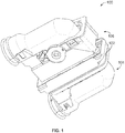
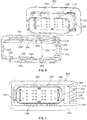
- FIG. 1 is an isometric view of a connector assembly 100 formed in accordance with an exemplary embodiment.
- the connector assembly 100 is configured to be panel mounted to a panel 102, such as a chassis, bulkhead, casing, and the like of a vehicle or machine.
- the connector assembly 100 is durable and capable of use in outdoor, rugged or extreme environments.
- the connector assembly 100 includes a cap connector 104 and a plug connector 106.
- the cap connector 104 is configured to be mounted to the panel 102 and the plug connector 106 is configured to be mated with the cap connector 104.
- Embodiments of the connector assembly 100 described herein provide a tool-less mounting arrangement. Embodiments of the connector assembly 100 provide temporary retention features that allow proper positioning and orientation of components, which may be further secured at a later time to complete the mating of the connectors 104, 106. Embodiments described herein have features that do not require a large access area around the connectors 104, 106 for assembly, allowing the connector assembly 100 to be positioned closer to other components or mounted into a smaller area of the panel 102. Embodiments of the connector assembly 100 provide features used to stabilize the terminal blocks of the cap and plug connectors 104, 106, thus reducing vibration and/or damage to the terminals of the connectors 104, 106.
- Embodiments of the connector assembly 100 allow for release of terminal position assurance (TPA) latches used to hold terminals in terminal blocks for ease of use.
- TPA terminal position assurance
- Embodiments of the connector assembly 100 provide a low stress hinge design for connection of various components that will work with a wide variety of materials.
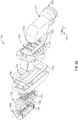
- Figures 2a and 2b show an exploded view of the connector assembly 100 showing the cap connector 104 and the plug connector 106.
- the cap connector 104 includes a cap housing 110, a wire cover 112, a mounting clip 114, a wire seal 116, a cap terminal block 118 and a cap TPA device 120.
- the plug connector 106 includes a plug housing 130, a wire cover 132, a slide lock mechanism 134, a wire seal 136, a plug terminal block 138 and a plug TPA device 140.
- An interface seal 142 is provided which may be positioned between the plug housing 130 and the cap housing 110 to seal the interface between the connectors 104, 106.
- the cap and plug connectors 104, 106 may include other components in alternative embodiments.
- the cap and plug connectors 104, 106 may be used without one or more of the components shown in Figures 2a and 2b , such as without the TPA devices 120, 140. Some of the components may be integral with other components rather than being separate components as shown in Figures 2a and 2b .
- the cap housing 110 holds wires and/or terminals 144 of the cap connector 104.
- the wire cover 112 is secured to the back end of the cap housing 110 to cover the wires and direct the wires through a cable exit 150 of the cap connector 104.
- the cable exit 150 may be defined in part by the cap housing 110 and in part by the wire cover 112.
- the wire cover 112 diverts high pressure spray, dirt and debris from entering the cap housing 110.
- the cap housing 110 includes channels 152 extending therethrough.
- the wires and/or terminals 144 may be loaded into the channels 152 and into the cap terminal block 118.
- the wires extending from the back end of the channels 152 are directed to the cable exit 150 by the wire cover 112.
- the cap housing 110 is configured to be mounted to the panel 102.
- the mounting clip 114 is used to securely couple the cap housing 110 to the panel 102.
- the cap housing 110 includes temporary retention features that temporarily secure the cap housing 110 to the panel 102 until the mounting clip 114 is able to be positioned and secured to the cap housing 110.
- the wire seal 116, cap terminal block 118 and cap TPA device 120 are loaded into the front end of the cap housing 110.
- the wire seal 116 seals against the wires associated with the cap terminals 144 of the cap connector 104.
- the wire seal 116 prevents exposure of the cap terminals 144 to dirt, debris and/or moisture through the cap housing 110.
- the cap terminal block 118 may be integral with and held in the cap housing 110 and thus not separately loaded into the cap housing 110.
- the cap terminal block 118 is used to hold the cap terminals 144.
- the cap terminal block 118 may have a plurality of individual cap terminal channels 154 that receive corresponding cap terminals 144. Latches 158 within each cap terminal channel 154 abut and hold the terminals 144 in the cap terminal channels 154.
- the cap TPA device 120 is coupled to the front of the cap terminal block 118.
- the cap TPA device 120 includes support walls 156 that extend into the cap terminal block 118. The support walls 156 provide support for the latches 158 in the cap terminal channels 154 to block the latches 158 from releasing, thus ensuring that the cap terminals 144 remain in the cap terminal channels 154.
- the cap TPA device 120 is movable between a blocking position and a retracted position. In the blocking position, the latches 158 are blocked by the support walls 156. In the retracted position, the support walls 156 are moved clear of the latches 158 to allow the latches 158 to release, allowing the cap terminals 144 to be removed from the cap terminal channels 154.
- the cap connector 104 may be used without the cap TPA device 120.
- the plug housing 130 holds wires and/or terminals 164 of the plug connector 106.
- the wire cover 132 is secured to the back end of the plug housing 130 to cover the wires and direct the wires through a cable exit 170 of the plug connector 106.
- the cable exit 170 may be defined in part by the plug housing 130 and in part by the wire cover 132.
- the wire cover 132 diverts high pressure spray, dirt and debris from entering the plug housing 130.
- the wires and/or terminals 164 may be loaded into the plug terminal block 138 from the plug housing 130. The wires are directed to the cable exit 170 by the wire cover 132.
- the plug housing 130 is configured to be coupled to the cap housing 110.
- the slide lock mechanism 134 is used to securely couple the plug housing 130 to the cap housing 110.
- the plug housing 130 may include temporary retention features that temporarily secure the plug housing 130 to the cap housing 110 until the slide lock mechanism 134 is able to be actuated to secure the plug housing 130 to the cap housing 110.
- the wire seal 136, plug terminal block 138 and plug TPA device 140 are loaded into the front end of the plug housing 130.
- the wire seal 136 seals against the wires associated with the plug terminals 164 of the plug connector 106.
- the wire seal 136 prevent exposure of the plug terminals 164 to dirt, debris and/or moisture through the plug housing 130.
- the plug terminal block 138 may be integral with and held in the plug housing 130 and thus not separately loaded into the plug housing 130.
- the plug terminal block 138 is used to hold the plug terminals.
- the plug terminal block 138 may have a plurality of individual plug terminal channels 174 that receive corresponding plug terminals. Latches 178 within each plug terminal channel 174 abut and hold the terminals in the plug terminal channels 174.
- the plug TPA device 140 is coupled to the front of the plug terminal block 138.
- the plug TPA device 140 includes support walls 176 that extend into the plug terminal block 138.
- the support walls 176 provide support for the latches 178 in the plug terminal channels 174 to block the latches 178 from releasing, thus ensuring that the plug terminals remain in the plug terminal channels 174.
- the plug TPA device 140 is movable between a blocking position and a retracted position.
- the plug connector 106 may be used without the plug TPA device 140.
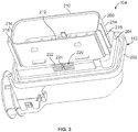
- FIG. 3 is an isometric view of the cap housing 110.
- the cap housing 110 includes an inner shroud 200 at a front of the cap housing 110 and an outer flange 202 proximate to a rear of the cap housing 110.
- the cap housing 110 includes an inner flange 204 between the inner shroud 200 and the outer flange 202.
- the inner flange 204 surrounds the inner shroud 200.
- the inner flange 204 may have a different periphery than the inner shroud 200.
- the inner flange 204 may be thicker than the inner shroud 200.
- the inner flange 204 may extend outward from one or more sides of the inner shroud 200.
- the inner flange 204 may have a different shape than the inner shroud 200.
- the inner shroud 200 has a generally rectangular shape with rounded corners.
- the inner shroud 200 may have other shapes in alternative embodiments.
- the inner shroud 200 includes a top 210, a bottom 212, a first side 214 and a second side 216 opposite the first side 214.
- the inner shroud 200 includes guide rails 218 along the sides 214, 216.
- the guide rails 218 may provide keyed mating with the plug connector 106 (shown in Figure 2b ).
- the inner flange 204 has a generally rectangular shape with rounded corners.
- the inner flange 204 extends outward beyond the top 210, bottom 212, and sides 214, 216.
- the inner flange 204 includes panel retention features 220 used to temporarily retain the cap housing 110 to the panel 102 (shown in Figures 4 and 5 ).
- the panel retention features 220 each include a plurality of ribs 222 independently movable with respect to one another and detents 224 extending from corresponding ribs 222.
- the ribs 222 and detents 224 are staged at different distances from the outer flange 202 to accommodate different panel thicknesses.
- the panel retention features 220 are provided along the top and the bottom of the inner flange 204 generally centrally positioned between the sides thereof. Other locations are possible in alternative embodiments. For example, the panel retention features 220 may be positioned at the corners in addition to or in lieu of being positioned at the centers of the top and the bottom. The panel retention features 220 may be positioned along the sides in addition to or in lieu of being positioned along the top and bottom.
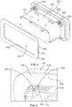
- FIGS. 4 and 5 show the cap housing 110 being mounted to the panel 102.
- the panel 102 includes an opening 230 defined by an edge 232.
- the panel 102 includes a front surface 234 and a rear surface 236.
- the opening 230 extends between the front and rear surfaces 234, 236.
- the cap housing 110 is mounted to the panel 102 by loading the inner shroud 200 through the opening 230.
- the panel retention features 220 engage the panel 102 and temporarily retain the cap housing 110 to the panel 102.
- the panel retention features 220 are provided in the corners as opposed to centered along the top and bottom of the inner flange 204.
- the cap housing 110 may be loaded into the opening 230 until the outer flange 202 engages the rear surface 236 of the panel 102.
- One or more of the detents 224 engage the front surface 234 (e.g. one detent 224 on the top and one detent 224 on the bottom) such that the cap housing 110 is held in place relative to the panel 102 between the outer flange 202 and the detents 224.
- the detents 224 may have sufficient strength to hold the cap housing 110 in place without the operator assisting or touching the cap housing 110. As such, the operator is able to use both hands to install the mounting clip 114 (shown in Figure 2a ) without needing to also hold the cap housing 110. A second operator is not needed to help install the cap housing 110 in position on the panel 102 as the cap housing 110 is temporarily self supporting.
- the panel retention features 220 are staged at different distances from the outer flange 202 to accommodate panels of different thicknesses.
- the panel retention feature 220 includes three ribs 222 each with a corresponding detent 224.
- the ribs 222 are independently movable to allow some flexibility when the detents 224 engage the panel 102.
- the detents 224 are ramped to allow the detents 224 to easily pass through the opening 230 during assembly.
- the detents 224 include generally vertical faces that engage the panel 102 and retain the cap housing 110 in position against the panel 102.
- Figure 6 illustrates a portion of the cap connector 104 showing the cap housing 110 temporarily mounted to the panel 102 and the mounting clip 114 poised for coupling to the cap housing 110.
- the mounting clip 114 is used to securely couple the cap housing 110 to the panel 102.
- the mounting clip 114 is designed to pass over the front of the cap housing 110 in a loading direction (e.g. generally toward the outer flange 202 and the panel 102) to engage the panel 102 and then slide along the panel 102 in a securing direction (e.g. generally parallel to the outer flange 202 and the panel 102). As the mounting clip 114 is slid in the securing direction, the cap housing 110 (e.g. the outer flange 202) is pulled tightly against the panel 102.
- a loading direction e.g. generally toward the outer flange 202 and the panel 102
- a securing direction e.g. generally parallel to the outer flange 202 and the panel 102
- the cap housing 110 When the mounting clip 114 is secured to the cap housing 110, the cap housing 110 is held tightly against the panel 102 and cannot be removed without removing the mounting clip 114. In contrast, when the panel retention features 220 temporarily retain the cap housing 110 to the panel 102, the cap housing 110 may be pressed out of the opening 230 by overcoming the retaining forces of the detents 224.
- the mounting clip 114 is a generally rectangular plate having a flange section 238 surrounding an opening 240.
- the flange section 238 is configured to be pressed against the panel 102 to secure the cap connector 104 to the panel 102.
- the opening 240 is surrounded by an edge 242.
- the edge 242 is defined by an upper wall 244, a lower wall 246, a first side wall 248 and a second side wall 250.
- the opening 240 is completely enclosed on all sides by the walls 244, 246, 248, 250.
- the opening 240 has a height 252 approximately equal to the height of the inner shroud 200 and/or inner flange 204.
- the opening 240 has a length 254 that is longer than a length of the inner shroud 200 and/or inner flange 204.
- the thickness of the mounting clip 114 may correspond to the thickness of the panel 102 to securely fit the mounting clip 114 between the panel 102 and the features of the cap housing 110 used to hold the mounting clip 114.
- the mounting clip 114 is slid sideways along the inner shroud 200 and the additional length 254 of the opening 240 allows the mounting clip 114 to slide relative to the cap housing 110.
- the inner shroud 200 includes detents 256 spaced apart from the outer flange 202.
- the detents 256 extend from the top 210 and the bottom 212; however the detents 256 may extend from other portions of the cap housing 110.
- the detents 256 are used to secure the mounting clip 114 to the cap housing 110.
- the mounting clip 114 includes windows 258 aligned with the detents 256.
- the windows 258 are sized and shaped to allow the detents 256 to pass through when the mounting clip 114 is loaded onto the cap housing 110.
- the mounting clip 114 is loaded onto the cap housing 110 in a loading direction generally toward the outer flange 202.
- the mounting clip 114 is loaded onto the cap housing 110 behind the detents 256 against the panel 102.
- the windows 258 allow the mounting clip 114 to be loaded straight over the inner shroud 200 and allow the mounting clip 114 to be positioned behind the detents 256.
- Figure 7 illustrates the cap connector 104 with the mounting clip 114 in a loaded but unlocked position.
- the mounting clip 114 In the loaded position, the mounting clip 114 is loaded over the inner shroud 200 and abuts against the front surface 234 of the panel 102.
- the mounting clip 114 is shifted to one side (e.g. to the right side) of the inner shroud 200 such that the inner shroud 200 is positioned proximate to the second side wall 250 and is positioned away from the first side wall 248.
- the mounting clip 114 includes rails 260 extending from the upper wall 244 and the lower wall 246.
- the rails 260 are configured to engage the detents 256 extending from the cap housing 110 to secure the cap housing 110 to the panel 102.
- the mounting clip 114 is slid in a securing direction along the panel 102 and the cap housing 110.
- the mounting clip 114 is slid to the left such that the position of the inner shroud 200 within the opening 240 changes as the mounting clip 114 is moved in the securing direction.
- the securing direction is generally parallel to the outer flange 202 and the panel 102.
- the rails 260 engage the detents 256.
- the rails 260 and/or the detents 256 are ramped or angled to drive the cap housing 110 forward, which snugs the outer flange 202 against the rear surface 236 of the panel 102.
- the mounting clip 114 is slid in the securing direction, the mounting clip 114 is pressed generally toward the outer flange 202 decreasing the spacing between the outer flange 202 and the mounting clip 114.
- the outer flange 202 and the mounting clip 114 are pressed against the panel 102 to hold the cap housing 110 tightly against the panel 102.
- Figure 8 illustrates the cap connector 104 showing the mounting clip 114 in a loaded and locked position.
- the mounting clip 114 is shown after being slid sideways along the panel 102 to secure the cap housing 110 to the panel 102.
- the mounting clip 114 includes a manual pad 262 that is used by the operator to push or press the mounting clip 114 in the securing direction.
- Latches 264 extending from the first side wall 248 on the mounting clip 114 engage the inner flange 204 to stop movement of the mounting clip 114 in the securing direction.
- the latches 264 position the mounting clip 114 with respect to the cap housing 110 in a locked position.
- the rails 260 engage the detents 256.
- the detents 256 and/or rails 260 may be shaped to hold the mounting clip 114 in the locked position.
- the cap connector 104 is configured for mating with the plug connector 106 (shown in Figure 1 ).
- Current mounting clips having a generally c-shaped design where the mounting clip is aligned extending from the side of the cap housing 110 to slide the open end of the c-shaped mounting clip onto the inner shroud 200.
- the closed mounting clip 114 is front loaded over the inner shroud 200 so that the inner shroud 200 fits within the opening 240.
- the closed mounting clip design shown in Figures 6-8 significantly less space is required to position the mounting clip 114 onto the cap housing 110 as compared to c-shape mounting clips.
- the amount of clearance space needed to the side (e.g. to the right) of the cap connector 104 is greatly reduced by the closed mounting clip design of the mounting clip 114 as compared to the c shaped design of the other mounting clips.
- Other components may be positioned closer to the connector assembly 100 by using such a design.
- Figures 9a and 9b illustrate a portion of the cap connector 104 showing the cap TPA device 120 poised for mounting to the cap terminal block 118.
- the cap terminal block 118 includes a top 270, a bottom 272 and sides 274 (only one side 274 shown in Figures 9a and 9b ) extending between the top 270 and the bottom 272.
- the cap terminal block 118 is elongated such that the top 270 and bottom 272 are longer than the sides 274.
- the cap terminal block 118 includes a plurality of detents 276 extending from the sides 274.
- the detents 276 are used to secure the cap TPA device 120 to the cap terminal block 118.
- the detents 276 include a ramp 278 and a catch surface 280.
- the ramps 278 are generally forward facing while the catch surfaces 280 are generally rearward facing.
- each side 274 of the cap terminal block 118 includes a plurality of detents 276 arranged in a staged configuration at different distances from a front 282 of the cap terminal block 118.
- the detents 276 are arranged at two stages with the catch surfaces 280 of the detents 276 at two different distances from the front 282.
- the near stage e.g. closer to the front 282 includes two detents 276 vertically offset toward the top 270 and bottom 272, respectively.
- the far stage (e.g. further from the front 282) includes a single detents 276 approximately centered between the top 270 and the bottom 272.
- Each of the stages may include any number of detents 276. Any number of stages may be provided.
- the stages of detents 276 are used to hold the cap TPA device 120 at different staged positions with respect to the cap terminal block 118. Staging of the cap TPA device 120 is used in assembly of the cap connector 104, such as for loading and unloading the cap terminals from the cap terminal block 118. For example, the cap terminals may only be loaded and unloaded from the cap terminal block 118 when the cap TPA device 120 is in a forward position, while insertion and removal of the cap terminals with respect to the cap terminal block 118 may be restricted when the cap TPA device 120 is in a rearward or locked position.
- the near detents 276 may be used to hold the cap TPA device 120 in the forward position while the far detents 276 may be used to hold the cap TPA device 120 in the rearward or locked position.
- the cap TPA device 120 includes hinged latches 290 extending from sides 292 of the cap TPA device 120 (only one latch 290 and side 292 is illustrated in Figures 9a and 9b , however a similar latch may be provided on the opposite side of the cap TPA device 120).
- the latches 290 each include a strap 294 supported by multiple hinges 296.
- the hinges 296 allow the strap 294 to rotate or move relative to the cap terminal block 118 to release the cap TPA device 120 from the cap terminal block 118.
- the hinges 296 define multiple connection points for connecting the latches 290 to the sides 292 of the cap TPA device 120.
- the cap TPA device 120 is coupled to the cap terminal block 118 such that the hinged latches 290 engage corresponding detents 276 of the cap terminal block 118.
- the hinged latched 290 are configured to be released from the detents 276 to uncouple the cap TPA device 120 from the cap terminal block 118, such as to allow the cap TPA device 120 to move from the rearward or locked positioned to the forward position and/or to allow the cap TPA device 120 to be entirely removed from the cap terminal block 118.
- the support walls 156 (shown in Figure 2a ) are moved out of a blocking position when the cap TPA device 120 is uncoupled from the cap terminal block 118 and moved to the forward or unblocking position and/or entirely removed from the cap terminal block 118.
- the latches 158 shown in Figure 2a
- the cap terminal block 118 are allowed to be released to remove the cap terminals from the cap terminal channels 154 (shown in Figure 2a ).
- the latches 290 distribute the stresses from securing the cap TPA device 120 to the cap terminal block 118 over a large surface area thus reducing stress concentrations for latch breakage.
- providing multiple hinges 296 provides multiple connection points increasing the surface area of connection between the latches 290 and the cap TPA device 120.
- the latches 290 have a rocker latch design rather than using a flexible wall which cannot be directly disengaged like a rocker latch.
- the hinges 296 provide both torsional and flexural hinge movements which spread the stresses out over a larger area and reduce stress concentrations that could lead to hinge fracture with some material.
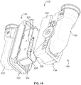
- Figure 10 is a partially exploded view of the connector assembly 100 showing the plug connector 106 poised for mating with the cap connector 104.
- Figure 11 is a partially exploded view of the connector assembly 100 showing the plug connector 106 poised for mating with the cap connector 104.
- the cap and plug connectors 104, 106 are shown in assembled states.
- the cap TPA device 120 is fully coupled to the cap terminal block 118 (shown in Figure 2a ) and received in the cap housing 110.
- the wire cover 112 is coupled to the cap housing 110.
- the mounting clip 114 is locked to secure the cap connector 104 to the panel 102.
- the plug TPA device 140 is shown coupled to the plug terminal block 138 (shown in Figure 2b ).
- the plug TPA device 140 may be secured to the plug terminal block 138 in a similar manner as the cap TPA device 120.
- the plug TPA device 140 may include hinged latches that are secured to detents extending from the plug terminal block 138.
- the wire cover 132 is coupled to the plug housing 130.
- the slide lock mechanism 134 is shown in an actuated position.
- the slide lock mechanism 134 is used to couple the plug connector 106 to the cap connector 104.
- the slide lock mechanism 134 may pull the plug connector 106 into the cap connector 104 as the slide lock mechanism 134 is actuated.
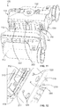
- the cap connector 104 includes a plurality of stabilizing post 300 extending from the cap terminal block 118.
- the stabilizing post 300 extend through the cap TPA device 120.
- the stabilizing posts 300 are coupled to the cap terminal block 118.
- the stabilizing post 300 may be integrally formed with the cap terminal block 118.
- the stabilizing posts 300 are coupled to the cap housing 110 and extend through the cap terminal block 118 and cap TPA device 120.
- the stabilizing post 300 may be coupled to the cap TPA device 120 and extend therefrom into the cap terminal block 118 to locate the cap TPA device 120 with respect to the cap terminal block 118 during assembly.
- the stabilizing posts 300 extend beyond the front of the cap TPA device 120 such that the stabilizing post 300 may extend into the plug connector 106.
- the plug TPA device 140 and plug terminal block 138 include holes 302 extending therethrough that received the stabilizing post 300.
- the stabilizing post 300 extend into the holes 302.
- the stabilizing post 300 link together the cap terminal block 118, the cap TPA device 120, the plug TPA device 140, and the plug terminal block 138 to stabilize the connection between the plug terminals and the cap terminals.
- the stabilizing post 300 may be received in the holes 302 by an interference fit such that any movement of the cap terminal block 118 may be transferred to the plug terminal block 138, and vice versa, by the stabilizing post 300.
- the stabilizing post 300 and corresponding holes 302 are located in each of the corners of the terminal blocks 118, 138 as well as in a central position along the tops and bottom thereof. Other locations are possible in alternative embodiments.
- the stabilizing post 300 provide for vibration stabilization.
- the stabilizing posts 300 may be used to just tie the terminal blocks 118, 138 together rather than the TPA devices 120, 140.
- some embodiments may not include TPA devices 120, 140 or the stabilizing posts 300 may not directly engage and hold the TPA devices 120, 140.
- Figure 12 illustrates a portion of the plug connector 100 showing the cap housing 110 and the plug housing 130. Internal components of the plug connector 106 are removed for clarity to illustrate an interior wall surface of the plug housing 130.
- the plug housing 130 includes temporary retention latches 310 on the interior of the top and bottom of the plug housing 130. The temporary retention latches 310 are used to temporarily secure the plug housing 130 to the cap housing 110 during assembly prior to using the slide lock mechanism 134 (shown in Figure 2b ) to more permanently secure the plug connector 106 to the cap connector 104.
- the temporary retention latches 310 includes flexible straps 312 that are able to be deflected outward when the plug housing 130 is loaded over the cap housing 110.
- the cap housing 110 includes detents 314 extending from the top 210 and from the bottom 212 (shown in Figure 3 ). The detents 314 cause the straps 312 to flex outward as the plug housing 130 is loaded over the cap housing 110. The detents 314 engage the back side of the straps 312 to temporarily secure the plug housing 130 to the cap housing 110.
- the securing force provided between the detents 314 and the temporary retention latches 310 is enough to support the plug housing 130 on the cap housing 110, however, such a securing force may be overcome by pulling the plug housing 130 off of the cap housing 110.
- the retention force between the detents 314 and the temporary retention latches 310 may be enough that the operator does not need to provide additional support to the plug housing 130 to retain the plug housing 130 temporarily on the cap housing 110.
- the slide lock mechanism 134 is used to more permanently secure the plug connector 106 to the cap connector 104.
- the cap housing 110 includes guide posts 320 extending from the top 210 and the bottom 212.
- the guide post 320 are loaded into the plug connector 106.
- the slide lock mechanism 134 engages the guide post 320 to secure the plug connector 106 to the cap connector 104.
- the plug housing 130 includes openings 322 in the top and bottom of the plug housing 130. The guide post 320 past thru the openings 322 and into the slide lock mechanism 134.
- the slide lock mechanism 134 includes a pair of slide locks 330 and a lever 332 used to actuate the slide locks 330.
- the lever 332 causes the slide locks 330 to translate in a sliding direction within the plug housing 130.
- the slide locks 330 receive the guide post 320 (shown in Figure 12 ).
- the slide locks 330 force the guide post 320 along a predefined path which pulls the plug connector 106 onto the cap connector 104.
- the lever 332 is actuated, the plug connector 106 is pulled into the cap connector 104.
- the plug terminals mate with the cap terminals. The mating force between the many plug and cap terminals is overcome by the force exerted by the lever 332 to tighten down the plug connector 106 to the cap connector 104.
- Embodiments of a panel mounted connector assembly include a series of retention latches to hold a cap connector into a panel mounting opening so a securing device can be applied on the other side of the panel.
- the retention latches temporarily retain the cap connector in the panel mounting opening so a single operator can insert and then move around to the other side of the panel to secure it in place.
- the retention features retain the cap connector and a lever or plug connector in position so an operator can remove their hand and re-grip the lever assist handle to complete the mating sequence.
- one panel retention feature can accommodate multiple panel thicknesses.
- Embodiments of a panel mounted connector assembly provide a tool-less mounting process that does not occupy a large access area in the process, provides terminal block-to-terminal block direct contact thus stabilizing one to the other, allows for release of the terminal position assurance (TPA) latches for ease of use, and provides a low-stress hinge design that will work with a wide variety of materials.
- TPA terminal position assurance
Landscapes
- Connector Housings Or Holding Contact Members (AREA)
Applications Claiming Priority (3)
| Application Number | Priority Date | Filing Date | Title |
|---|---|---|---|
| US201261632581P | 2012-01-26 | 2012-01-26 | |
| US13/749,473 US9033729B2 (en) | 2012-01-26 | 2013-01-24 | Panel mounted connector assembly |
| PCT/US2013/023091 WO2013112800A1 (en) | 2012-01-26 | 2013-01-25 | Panel mounted connector assembly |
Publications (2)
| Publication Number | Publication Date |
|---|---|
| EP2807708A1 EP2807708A1 (en) | 2014-12-03 |
| EP2807708B1 true EP2807708B1 (en) | 2017-03-22 |
Family
ID=48870593
Family Applications (1)
| Application Number | Title | Priority Date | Filing Date |
|---|---|---|---|
| EP13702863.5A Active EP2807708B1 (en) | 2012-01-26 | 2013-01-25 | Panel mounted connector assembly |
Country Status (5)
| Country | Link |
|---|---|
| US (1) | US9033729B2 (enExample) |
| EP (1) | EP2807708B1 (enExample) |
| JP (1) | JP6041903B2 (enExample) |
| CN (1) | CN104106183B (enExample) |
| WO (1) | WO2013112800A1 (enExample) |
Families Citing this family (7)
| Publication number | Priority date | Publication date | Assignee | Title |
|---|---|---|---|---|
| DE102014103991A1 (de) * | 2014-03-24 | 2015-09-24 | Phoenix Contact Gmbh & Co. Kg | Verbindungsanordnung |
| KR102226323B1 (ko) * | 2014-06-25 | 2021-03-11 | 타이코에이엠피 주식회사 | 헤더 어셈블리 및 이를 구비하는 차량용 커넥터 장치 |
| US9620265B2 (en) * | 2015-01-21 | 2017-04-11 | Te Connectivity Corporation | Sealed header assembly |
| JP6185960B2 (ja) * | 2015-05-27 | 2017-08-23 | 矢崎総業株式会社 | コネクタ |
| JP6580548B2 (ja) * | 2016-12-22 | 2019-09-25 | 矢崎総業株式会社 | コネクタ |
| JP6943917B2 (ja) * | 2019-03-29 | 2021-10-06 | 矢崎総業株式会社 | コネクタ |
| JP2021031000A (ja) * | 2019-08-29 | 2021-03-01 | ロベルト・ボッシュ・ゲゼルシャフト・ミト・ベシュレンクテル・ハフツングRobert Bosch Gmbh | 液圧制御ユニット、ブレーキシステム及び鞍乗型車両 |
Family Cites Families (19)
| Publication number | Priority date | Publication date | Assignee | Title |
|---|---|---|---|---|
| JPS6035976Y2 (ja) * | 1982-11-12 | 1985-10-25 | ヒロセ電機株式会社 | 電気コネクタのパネル取付け機構 |
| US5037325A (en) * | 1990-10-05 | 1991-08-06 | Molex Incorporated | Panel mounted electrical connector |
| US5181865A (en) | 1992-02-21 | 1993-01-26 | Amp Incorporated | Electrical connector with secondary locking |
| GB9219328D0 (en) * | 1992-09-11 | 1992-10-28 | Amp Gmbh | Automotive door-to-body electrical |
| US5607323A (en) * | 1994-12-19 | 1997-03-04 | Itt Corporation | Snap adapter |
| JPH08306439A (ja) * | 1995-05-08 | 1996-11-22 | Yazaki Corp | コネクタのパネルへの取付構造 |
| JP3278048B2 (ja) * | 1997-10-01 | 2002-04-30 | 住友電装株式会社 | コネクタ |
| US5904584A (en) * | 1997-10-28 | 1999-05-18 | General Motors Corporation | Slide assisted grommet assembly |
| JP3541695B2 (ja) * | 1998-11-11 | 2004-07-14 | 住友電装株式会社 | パネル取付型コネクタ |
| US6312285B1 (en) * | 1999-02-25 | 2001-11-06 | Molex Incorporated | Panel mounting system for electrical connectors |
| US6247966B1 (en) * | 1999-10-04 | 2001-06-19 | Tyco Electronics Corp. | Electrical connector with exposed molded latches |
| US6126484A (en) * | 1999-11-01 | 2000-10-03 | The Whitaker Corporation | Electrical connector with molded latch stop |
| US6513206B1 (en) | 2001-07-20 | 2003-02-04 | International Business Machines Corporation | Retaining clip for panel mounted input/output connector |
| JP3944180B2 (ja) * | 2004-03-12 | 2007-07-11 | 矢崎総業株式会社 | コネクタ |
| US7601913B2 (en) | 2005-04-04 | 2009-10-13 | Samsung Gwangju Electronics Co., Ltd. | Wire harness fixing device |
| KR100684550B1 (ko) * | 2005-04-04 | 2007-02-20 | 삼성광주전자 주식회사 | 와이어 하네스 고정장치 |
| KR101552353B1 (ko) * | 2006-10-18 | 2015-09-10 | 타이코에이엠피 주식회사 | 차량 도어용 케이블 연결 커넥터 |
| US7637766B2 (en) * | 2007-09-21 | 2009-12-29 | Howard Industries, Inc. | Photocontrol receptacle |
| TWI353431B (en) | 2008-11-21 | 2011-12-01 | Au Optronics Corp | Back light unit and lamp socket thereof |
-
2013
- 2013-01-24 US US13/749,473 patent/US9033729B2/en active Active
- 2013-01-25 EP EP13702863.5A patent/EP2807708B1/en active Active
- 2013-01-25 WO PCT/US2013/023091 patent/WO2013112800A1/en not_active Ceased
- 2013-01-25 CN CN201380006624.8A patent/CN104106183B/zh active Active
- 2013-01-25 JP JP2014554842A patent/JP6041903B2/ja not_active Expired - Fee Related
Non-Patent Citations (1)
| Title |
|---|
| None * |
Also Published As
| Publication number | Publication date |
|---|---|
| US9033729B2 (en) | 2015-05-19 |
| CN104106183A (zh) | 2014-10-15 |
| JP2015510227A (ja) | 2015-04-02 |
| CN104106183B (zh) | 2016-11-23 |
| US20130196537A1 (en) | 2013-08-01 |
| EP2807708A1 (en) | 2014-12-03 |
| JP6041903B2 (ja) | 2016-12-14 |
| WO2013112800A1 (en) | 2013-08-01 |
Similar Documents
| Publication | Publication Date | Title |
|---|---|---|
| EP2807708B1 (en) | Panel mounted connector assembly | |
| EP1914847B1 (en) | Cable connector for vehicle door | |
| KR100946917B1 (ko) | 위치 확정 장치를 구비하는 레버 결합식 커넥터 어셈블리 | |
| EP2311151B1 (en) | Checkable plug-in connection and method for checking the connection state of a plug-in connection | |
| EP3176804B1 (en) | Snap-lock relay socket | |
| KR102887879B1 (ko) | 커넥터 및 이 커넥터를 포함하는 커넥터조립체 | |
| KR20160032682A (ko) | 수리 가능한 커넥터용 고정 시스템 | |
| KR20140139577A (ko) | 커넥터를 조립하기 위한 구조 및 방법 | |
| KR101632557B1 (ko) | 레버 타입 커넥터 | |
| CN114597692A (zh) | 用于插接式连接器的保持框架和组装保持框架的方法 | |
| CN101971434B (zh) | 连接器护盖 | |
| CA2603263A1 (en) | Plug-in connection | |
| EP3849025A1 (en) | Hv connector having a rear grid with strain relief means and method for assembling thereof | |
| JP6521066B2 (ja) | コネクタ | |
| WO2008084339A1 (en) | Electrical connector assembly with improved locking means | |
| EP2111674B1 (en) | Confined envelope connector system | |
| KR20180010934A (ko) | 보호판을 구비한 커넥터 어셈블리 | |
| JP2011138984A (ja) | 脱着機構及びそれを用いた電子装置 | |
| US10135188B2 (en) | Enclosure assembly for an electrical connector and same | |
| WO2021015992A1 (en) | Din rail mounting clamp | |
| EP3799222A1 (en) | Male plug, pin cover, system and method for providing a male plug of a system | |
| KR20170063255A (ko) | 커넥터 장치 | |
| KR102882006B1 (ko) | 전기 커넥터 | |
| EP1117157B1 (en) | Holding means for electrical connector | |
| EP3716743B1 (en) | Removable cable arm bracket |
Legal Events
| Date | Code | Title | Description |
|---|---|---|---|
| PUAI | Public reference made under article 153(3) epc to a published international application that has entered the european phase |
Free format text: ORIGINAL CODE: 0009012 |
|
| 17P | Request for examination filed |
Effective date: 20140716 |
|
| AK | Designated contracting states |
Kind code of ref document: A1 Designated state(s): AL AT BE BG CH CY CZ DE DK EE ES FI FR GB GR HR HU IE IS IT LI LT LU LV MC MK MT NL NO PL PT RO RS SE SI SK SM TR |
|
| DAX | Request for extension of the european patent (deleted) | ||
| GRAP | Despatch of communication of intention to grant a patent |
Free format text: ORIGINAL CODE: EPIDOSNIGR1 |
|
| INTG | Intention to grant announced |
Effective date: 20161011 |
|
| GRAS | Grant fee paid |
Free format text: ORIGINAL CODE: EPIDOSNIGR3 |
|
| RAP1 | Party data changed (applicant data changed or rights of an application transferred) |
Owner name: TE CONNECTIVITY CORPORATION |
|
| GRAA | (expected) grant |
Free format text: ORIGINAL CODE: 0009210 |
|
| AK | Designated contracting states |
Kind code of ref document: B1 Designated state(s): AL AT BE BG CH CY CZ DE DK EE ES FI FR GB GR HR HU IE IS IT LI LT LU LV MC MK MT NL NO PL PT RO RS SE SI SK SM TR |
|
| REG | Reference to a national code |
Ref country code: GB Ref legal event code: FG4D |
|
| REG | Reference to a national code |
Ref country code: CH Ref legal event code: EP |
|
| REG | Reference to a national code |
Ref country code: AT Ref legal event code: REF Ref document number: 878602 Country of ref document: AT Kind code of ref document: T Effective date: 20170415 |
|
| REG | Reference to a national code |
Ref country code: IE Ref legal event code: FG4D |
|
| REG | Reference to a national code |
Ref country code: DE Ref legal event code: R096 Ref document number: 602013018846 Country of ref document: DE |
|
| REG | Reference to a national code |
Ref country code: NL Ref legal event code: FP |
|
| REG | Reference to a national code |
Ref country code: SE Ref legal event code: TRGR |
|
| PG25 | Lapsed in a contracting state [announced via postgrant information from national office to epo] |
Ref country code: FI Free format text: LAPSE BECAUSE OF FAILURE TO SUBMIT A TRANSLATION OF THE DESCRIPTION OR TO PAY THE FEE WITHIN THE PRESCRIBED TIME-LIMIT Effective date: 20170322 Ref country code: LT Free format text: LAPSE BECAUSE OF FAILURE TO SUBMIT A TRANSLATION OF THE DESCRIPTION OR TO PAY THE FEE WITHIN THE PRESCRIBED TIME-LIMIT Effective date: 20170322 Ref country code: HR Free format text: LAPSE BECAUSE OF FAILURE TO SUBMIT A TRANSLATION OF THE DESCRIPTION OR TO PAY THE FEE WITHIN THE PRESCRIBED TIME-LIMIT Effective date: 20170322 Ref country code: GR Free format text: LAPSE BECAUSE OF FAILURE TO SUBMIT A TRANSLATION OF THE DESCRIPTION OR TO PAY THE FEE WITHIN THE PRESCRIBED TIME-LIMIT Effective date: 20170623 Ref country code: NO Free format text: LAPSE BECAUSE OF FAILURE TO SUBMIT A TRANSLATION OF THE DESCRIPTION OR TO PAY THE FEE WITHIN THE PRESCRIBED TIME-LIMIT Effective date: 20170622 |
|
| REG | Reference to a national code |
Ref country code: LT Ref legal event code: MG4D |
|
| REG | Reference to a national code |
Ref country code: AT Ref legal event code: MK05 Ref document number: 878602 Country of ref document: AT Kind code of ref document: T Effective date: 20170322 |
|
| PG25 | Lapsed in a contracting state [announced via postgrant information from national office to epo] |
Ref country code: BG Free format text: LAPSE BECAUSE OF FAILURE TO SUBMIT A TRANSLATION OF THE DESCRIPTION OR TO PAY THE FEE WITHIN THE PRESCRIBED TIME-LIMIT Effective date: 20170622 Ref country code: LV Free format text: LAPSE BECAUSE OF FAILURE TO SUBMIT A TRANSLATION OF THE DESCRIPTION OR TO PAY THE FEE WITHIN THE PRESCRIBED TIME-LIMIT Effective date: 20170322 Ref country code: RS Free format text: LAPSE BECAUSE OF FAILURE TO SUBMIT A TRANSLATION OF THE DESCRIPTION OR TO PAY THE FEE WITHIN THE PRESCRIBED TIME-LIMIT Effective date: 20170322 |
|
| PG25 | Lapsed in a contracting state [announced via postgrant information from national office to epo] |
Ref country code: EE Free format text: LAPSE BECAUSE OF FAILURE TO SUBMIT A TRANSLATION OF THE DESCRIPTION OR TO PAY THE FEE WITHIN THE PRESCRIBED TIME-LIMIT Effective date: 20170322 Ref country code: AT Free format text: LAPSE BECAUSE OF FAILURE TO SUBMIT A TRANSLATION OF THE DESCRIPTION OR TO PAY THE FEE WITHIN THE PRESCRIBED TIME-LIMIT Effective date: 20170322 Ref country code: SK Free format text: LAPSE BECAUSE OF FAILURE TO SUBMIT A TRANSLATION OF THE DESCRIPTION OR TO PAY THE FEE WITHIN THE PRESCRIBED TIME-LIMIT Effective date: 20170322 Ref country code: CZ Free format text: LAPSE BECAUSE OF FAILURE TO SUBMIT A TRANSLATION OF THE DESCRIPTION OR TO PAY THE FEE WITHIN THE PRESCRIBED TIME-LIMIT Effective date: 20170322 Ref country code: ES Free format text: LAPSE BECAUSE OF FAILURE TO SUBMIT A TRANSLATION OF THE DESCRIPTION OR TO PAY THE FEE WITHIN THE PRESCRIBED TIME-LIMIT Effective date: 20170322 Ref country code: RO Free format text: LAPSE BECAUSE OF FAILURE TO SUBMIT A TRANSLATION OF THE DESCRIPTION OR TO PAY THE FEE WITHIN THE PRESCRIBED TIME-LIMIT Effective date: 20170322 |
|
| PG25 | Lapsed in a contracting state [announced via postgrant information from national office to epo] |
Ref country code: IS Free format text: LAPSE BECAUSE OF FAILURE TO SUBMIT A TRANSLATION OF THE DESCRIPTION OR TO PAY THE FEE WITHIN THE PRESCRIBED TIME-LIMIT Effective date: 20170722 Ref country code: SM Free format text: LAPSE BECAUSE OF FAILURE TO SUBMIT A TRANSLATION OF THE DESCRIPTION OR TO PAY THE FEE WITHIN THE PRESCRIBED TIME-LIMIT Effective date: 20170322 Ref country code: PL Free format text: LAPSE BECAUSE OF FAILURE TO SUBMIT A TRANSLATION OF THE DESCRIPTION OR TO PAY THE FEE WITHIN THE PRESCRIBED TIME-LIMIT Effective date: 20170322 Ref country code: PT Free format text: LAPSE BECAUSE OF FAILURE TO SUBMIT A TRANSLATION OF THE DESCRIPTION OR TO PAY THE FEE WITHIN THE PRESCRIBED TIME-LIMIT Effective date: 20170724 |
|
| REG | Reference to a national code |
Ref country code: FR Ref legal event code: PLFP Year of fee payment: 6 |
|
| REG | Reference to a national code |
Ref country code: DE Ref legal event code: R097 Ref document number: 602013018846 Country of ref document: DE |
|
| PLBE | No opposition filed within time limit |
Free format text: ORIGINAL CODE: 0009261 |
|
| STAA | Information on the status of an ep patent application or granted ep patent |
Free format text: STATUS: NO OPPOSITION FILED WITHIN TIME LIMIT |
|
| PG25 | Lapsed in a contracting state [announced via postgrant information from national office to epo] |
Ref country code: DK Free format text: LAPSE BECAUSE OF FAILURE TO SUBMIT A TRANSLATION OF THE DESCRIPTION OR TO PAY THE FEE WITHIN THE PRESCRIBED TIME-LIMIT Effective date: 20170322 |
|
| 26N | No opposition filed |
Effective date: 20180102 |
|
| PG25 | Lapsed in a contracting state [announced via postgrant information from national office to epo] |
Ref country code: SI Free format text: LAPSE BECAUSE OF FAILURE TO SUBMIT A TRANSLATION OF THE DESCRIPTION OR TO PAY THE FEE WITHIN THE PRESCRIBED TIME-LIMIT Effective date: 20170322 Ref country code: IT Free format text: LAPSE BECAUSE OF FAILURE TO SUBMIT A TRANSLATION OF THE DESCRIPTION OR TO PAY THE FEE WITHIN THE PRESCRIBED TIME-LIMIT Effective date: 20170322 |
|
| REG | Reference to a national code |
Ref country code: CH Ref legal event code: PL |
|
| PG25 | Lapsed in a contracting state [announced via postgrant information from national office to epo] |
Ref country code: LU Free format text: LAPSE BECAUSE OF NON-PAYMENT OF DUE FEES Effective date: 20180125 |
|
| REG | Reference to a national code |
Ref country code: IE Ref legal event code: MM4A |
|
| REG | Reference to a national code |
Ref country code: BE Ref legal event code: MM Effective date: 20180131 |
|
| PG25 | Lapsed in a contracting state [announced via postgrant information from national office to epo] |
Ref country code: CH Free format text: LAPSE BECAUSE OF NON-PAYMENT OF DUE FEES Effective date: 20180131 Ref country code: LI Free format text: LAPSE BECAUSE OF NON-PAYMENT OF DUE FEES Effective date: 20180131 Ref country code: BE Free format text: LAPSE BECAUSE OF NON-PAYMENT OF DUE FEES Effective date: 20180131 |
|
| PG25 | Lapsed in a contracting state [announced via postgrant information from national office to epo] |
Ref country code: IE Free format text: LAPSE BECAUSE OF NON-PAYMENT OF DUE FEES Effective date: 20180125 |
|
| PG25 | Lapsed in a contracting state [announced via postgrant information from national office to epo] |
Ref country code: MC Free format text: LAPSE BECAUSE OF FAILURE TO SUBMIT A TRANSLATION OF THE DESCRIPTION OR TO PAY THE FEE WITHIN THE PRESCRIBED TIME-LIMIT Effective date: 20170322 |
|
| PG25 | Lapsed in a contracting state [announced via postgrant information from national office to epo] |
Ref country code: MT Free format text: LAPSE BECAUSE OF NON-PAYMENT OF DUE FEES Effective date: 20180125 |
|
| PGFP | Annual fee paid to national office [announced via postgrant information from national office to epo] |
Ref country code: FR Payment date: 20191216 Year of fee payment: 8 |
|
| PG25 | Lapsed in a contracting state [announced via postgrant information from national office to epo] |
Ref country code: TR Free format text: LAPSE BECAUSE OF FAILURE TO SUBMIT A TRANSLATION OF THE DESCRIPTION OR TO PAY THE FEE WITHIN THE PRESCRIBED TIME-LIMIT Effective date: 20170322 |
|
| PGFP | Annual fee paid to national office [announced via postgrant information from national office to epo] |
Ref country code: GB Payment date: 20200115 Year of fee payment: 8 Ref country code: SE Payment date: 20200110 Year of fee payment: 8 Ref country code: NL Payment date: 20200130 Year of fee payment: 8 |
|
| PG25 | Lapsed in a contracting state [announced via postgrant information from national office to epo] |
Ref country code: HU Free format text: LAPSE BECAUSE OF FAILURE TO SUBMIT A TRANSLATION OF THE DESCRIPTION OR TO PAY THE FEE WITHIN THE PRESCRIBED TIME-LIMIT; INVALID AB INITIO Effective date: 20130125 |
|
| PG25 | Lapsed in a contracting state [announced via postgrant information from national office to epo] |
Ref country code: MK Free format text: LAPSE BECAUSE OF NON-PAYMENT OF DUE FEES Effective date: 20170322 Ref country code: CY Free format text: LAPSE BECAUSE OF FAILURE TO SUBMIT A TRANSLATION OF THE DESCRIPTION OR TO PAY THE FEE WITHIN THE PRESCRIBED TIME-LIMIT Effective date: 20170322 |
|
| PG25 | Lapsed in a contracting state [announced via postgrant information from national office to epo] |
Ref country code: AL Free format text: LAPSE BECAUSE OF FAILURE TO SUBMIT A TRANSLATION OF THE DESCRIPTION OR TO PAY THE FEE WITHIN THE PRESCRIBED TIME-LIMIT Effective date: 20170322 |
|
| REG | Reference to a national code |
Ref country code: SE Ref legal event code: EUG |
|
| REG | Reference to a national code |
Ref country code: NL Ref legal event code: MM Effective date: 20210201 |
|
| GBPC | Gb: european patent ceased through non-payment of renewal fee |
Effective date: 20210125 |
|
| PG25 | Lapsed in a contracting state [announced via postgrant information from national office to epo] |
Ref country code: FR Free format text: LAPSE BECAUSE OF NON-PAYMENT OF DUE FEES Effective date: 20210131 Ref country code: NL Free format text: LAPSE BECAUSE OF NON-PAYMENT OF DUE FEES Effective date: 20210201 |
|
| PG25 | Lapsed in a contracting state [announced via postgrant information from national office to epo] |
Ref country code: GB Free format text: LAPSE BECAUSE OF NON-PAYMENT OF DUE FEES Effective date: 20210125 Ref country code: SE Free format text: LAPSE BECAUSE OF NON-PAYMENT OF DUE FEES Effective date: 20210126 |
|
| PGFP | Annual fee paid to national office [announced via postgrant information from national office to epo] |
Ref country code: DE Payment date: 20251203 Year of fee payment: 14 |