EP2807661B1 - Compact structure for an electromagnetic component, and electromagnetic component for, in particular, heat-engine coils - Google Patents
Compact structure for an electromagnetic component, and electromagnetic component for, in particular, heat-engine coils Download PDFInfo
- Publication number
- EP2807661B1 EP2807661B1 EP13704205.7A EP13704205A EP2807661B1 EP 2807661 B1 EP2807661 B1 EP 2807661B1 EP 13704205 A EP13704205 A EP 13704205A EP 2807661 B1 EP2807661 B1 EP 2807661B1
- Authority
- EP
- European Patent Office
- Prior art keywords
- electromagnetic component
- winding
- component structure
- electromagnetic
- structure according
- Prior art date
- Legal status (The legal status is an assumption and is not a legal conclusion. Google has not performed a legal analysis and makes no representation as to the accuracy of the status listed.)
- Active
Links
Images

Classifications
-
- H—ELECTRICITY
- H01—ELECTRIC ELEMENTS
- H01F—MAGNETS; INDUCTANCES; TRANSFORMERS; SELECTION OF MATERIALS FOR THEIR MAGNETIC PROPERTIES
- H01F3/00—Cores, Yokes, or armatures
- H01F3/02—Cores, Yokes, or armatures made from sheets
-
- H—ELECTRICITY
- H01—ELECTRIC ELEMENTS
- H01F—MAGNETS; INDUCTANCES; TRANSFORMERS; SELECTION OF MATERIALS FOR THEIR MAGNETIC PROPERTIES
- H01F5/00—Coils
- H01F5/02—Coils wound on non-magnetic supports, e.g. formers
-
- H—ELECTRICITY
- H01—ELECTRIC ELEMENTS
- H01F—MAGNETS; INDUCTANCES; TRANSFORMERS; SELECTION OF MATERIALS FOR THEIR MAGNETIC PROPERTIES
- H01F38/00—Adaptations of transformers or inductances for specific applications or functions
- H01F38/12—Ignition, e.g. for IC engines
Definitions
- the present invention relates to the technical field of electromagnetic components in the general sense and more specifically to the electromagnetic components used in the field of motor vehicles.
- the object of the invention finds a particularly advantageous application in the field of producing ignition coils for combustion engines internal combustion.
- the object of the invention also finds particularly advantageous applications for electromagnetic sensors or for electromagnetic actuators for controlling a movable member for a heat engine and in particular for an injector of a heat engine.
- the patent FR 2,661,216 discloses an ignition coil comprising a magnetic circuit provided on the one hand, a magnetic core around which are wound a primary winding and a secondary winding and secondly, a closing loop of the magnetic circuit having an extended main branch on both sides, by branches of return.
- an ignition coil comprising a perforated coil carcass internally defining a housing of a magnetic core and externally, a tubular winding casing for a primary winding.
- the electronic component structure comprises at least a first winding carcass internally delimiting a housing of a magnetic core and externally, a tubular winding envelope of at least one winding of an electrical conductor wire.
- the magnetic core has a transverse cross section with four branches defining two by two, four housings and in that the winding carcass comprises four longitudinal members extending in the housing parallel to each other by delimiting the tubular winding casing, the beams being connected together at each of their ends by two connecting frames.
- Another object of the invention is to provide an electromagnetic component forming an ignition module, comprising an electromagnetic component structure according to the invention.
- Another object of the invention is to provide an ignition coil for an internal combustion engine comprising an ignition module.
- Another object of the invention is to provide an electromagnetic actuator for controlling a movable member for a heat engine, comprising an electromagnetic component structure according to the invention.
- Another object of the invention is to propose an electromagnetic component forming an electromagnetic control actuator a shutter for an engine injector, comprising an electromagnetic component structure according to the invention.
- Another object of the invention is to propose an electromagnetic component forming an electromagnetic measurement sensor, comprising an electromagnetic component structure according to the invention.
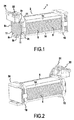
- the Fig. 1 to 5 illustrate an exemplary embodiment of a structure 1 for an electromagnetic component comprising at least a first winding carcass 2 for an electrical conductor wire 3.
- the winding carcass 2 internally defines a housing 4 for a magnetic core 5 and externally, an envelope tubular winding E for at least one winding of an electrical conductor wire 3.
- the magnetic core 5 is in the form of a parallelepipedal body having a cross-sectional cross-section with four branches to namely two opposite vertical branches 8 1 , 8 2 and two opposite horizontal branches 8 3 , 8 4 .
- the four branches 8 1 to 8 4 delimit two by two, four housings 11.
- the magnetic core 5 is constituted by magnetic sheets stacked parallel to each other and cut so that in assembled position, they form together the magnetic core 5 in the form of a cross.
- the magnetic core 5 comprises a first series of magnetic sheets 5 1 having a specific profile and a second series of magnetic sheets 5 2 having a cutting profile forming part of the cutting profile of the magnetic sheets 5 1 of the first series.
- the magnetic sheets 5 2 of the second series which all have the same profile are disposed on both sides of the magnetic sheets 5 1 of the first series also.
- the laminations 5 2 of the second series have a width which is less than the width of the laminations 5 1 of the first series.
- the laminations 5 2 of the second group are centered with respect to laminations 5 1 of the first series so as to define the housing 11 of identical volume.
- the ends of the magnetic sheets 5 1 protruding from the magnetic sheets 5 2 of the second series constitute the horizontal branches 8 3 , 8 4 while the opposite vertical branches 8 1 , 8 2 are formed by the sheets Magnetic 5 2 of the second series.
- the winding carcass 2 comprises four longitudinal members 13 defining together the tubular winding envelope E, of which only one section is shown schematically in FIG. Fig. 3 . More specifically, the longitudinal members 13 each have a rounded surface 14 on which the electrical conductor wire 3 is wound. The rounded surfaces 14 of the longitudinal members 13 delimit the tubular winding envelope E extending over the entire length of the longitudinal members 13. For example, each rounded surface 14 has a shape comparable to a quarter circle.
- each spar 13 extends parallel to each other by defining between them a parallelepiped whose interior corresponding to the housing 4 for the magnetic core 5.
- each spar 13 extends into a housing 11.
- the longitudinal members 13 are located at the four corners of the magnetic core 5.
- the rounded surfaces 14 of the longitudinal members 13 are positioned in such a way that the tubular winding envelope E defined by these surfaces extends in projection relative to the magnetic core 5.
- the The tubular winding envelope E is spaced apart from the outer surface of the magnetic core 5 by a gap or a determined interval so that the winding of the electrical conductor wire 3 does not touch the magnetic core 5. It should be understood that most of the the thickness of the longitudinal members 13 is positioned inside the housings 11 to limit the bulk of the structure.
- the longitudinal members 13 are connected together at one of their ends by means of a first connecting frame 15 and at the other of their ends, by means of a second connecting frame 16.
- the longitudinal members 13 have a length less than the length of the magnetic core 5 so that the connecting frames 15, 16 surround the magnetic core 5 near each of its ends.
- the connecting frames 15, 16 thus serve to hold the magnetic sheets 5 1 , 5 2 which are engaged inside the connecting frames 15, 16.
- the magnetic sheets 5 2 of the second series are positioned between the two lower longitudinal members and between the two upper longitudinal members, in consideration of the position of the winding carcass 2 illustrated in the drawings.
- the magnetic sheets 5 1 of the first series are positioned between the upper spars and the lower spars.
- each spar 13 is provided with two lateral faces 18 perpendicular to each other.
- a side surface 18 extends on either side of a rounded surface 14 of a spar 13.
- the two lateral faces 18 ensure the positioning and maintenance of the magnetic core 5 and in particular, magnetic sheets 5 1 , 5 2 .
- the two lateral faces 18 may be contiguous. However, preferably, the two lateral faces 18 are interconnected by an oblique connecting surface 19 making it possible to truncate the angle between the two lateral faces 18.
- At least one connecting frame namely the connecting frame 15 in the illustrated example, comprises a mechanical holding system 21 of the ends of the electrical conductor wire 3 of the winding.
- the mechanical winding system 21 which protrudes from the connecting frame 15 can be made in any suitable manner.
- the mechanical holding system 21 may include retaining pins for the electrical conductor wire 3.
- at least one connecting frame, namely, the connecting frame 15 is provided with a system electrical connection 22 for the conductive wire 3 of the winding.
- the electrical connection system 22 is for example made by a connector carried by the connecting frame 15.
- At least the second connecting part 16 is equipped with a location device 24 and holding a magnet or a gap wedge 25.
- the holding device 24 is made in illustrated example, by lugs 25 extending axially from the connecting frame 16, opposite the housing 4.
- the connecting frames 15, 16 comprise a positioning system 26 for a second winding carcass 27 inside which the first winding carcass 2 is engaged .
- the system positioning device 26 is constituted by pins arranged on the connecting frames 15 and 16 to constitute a receiving surface of a second winding carcass 27 on which can be wound an electrical conductor wire to constitute a second winding of a conductive wire electric.
- the first winding carcass 2 provided with the electrical conductor wire 3 is fitted inside the second winding carcass 27. It is thus possible to produce an electromagnetic component structure comprising two concentric windings.
- the bulk of the electromagnetic component structure 1 is optimized by the production of a winding carcass 2 limited to the longitudinal members 13 , part of which extends inside the magnetic core 5.
- winding of the electrical conductor wire 3 is provided in good conditions by its winding on the rounded surfaces 14 of the side members 13.
- Such a structure has an improved compactness compared to the structures of the state of the art.
- the electromagnetic component structure 1 as described above can be used for many applications.
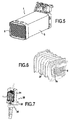
- the Fig. 7 illustrates an example of integration of the structure 1 in an electromagnetic component such as a coil 30 of the type top plug.
- this coil comprises a housing 31 for receiving the structure 1 provided with a winding structure 2 for an excitation winding of an electrical conductor wire and a second winding housing 27 for an excitation winding. an electrical conductor wire.
- the magnetic core 5 of this structure and the two excitation windings wound on the carcasses 2, 27 are part of a magnetic circuit which can be completed by a closure branch including or not, a magnet.
- the housing 31 for receiving the structure 1 is provided with fixing means 32 to the motor.
- This coil 31 also comprises connecting means 33 and connection to a spark plug.
- the structure 1 according to the invention can also be used for an electromagnetic actuator for controlling a movable member for a heat engine, such as for an engine injector.
- the structure 1 according to the invention can be used for an electromagnetic measuring sensor.
Landscapes
- Engineering & Computer Science (AREA)
- Power Engineering (AREA)
- Electromagnets (AREA)
- Windings For Motors And Generators (AREA)
Description
La présente invention concerne le domaine technique des composants électromagnétiques au sens général et elle vise plus précisément les composants électromagnétiques utilisés dans le domaine des véhicules automobiles.The present invention relates to the technical field of electromagnetic components in the general sense and more specifically to the electromagnetic components used in the field of motor vehicles.
L'objet de l'invention trouve une application particulièrement avantageuse dans le domaine de la réalisation de bobines d'allumage pour moteurs thermiques à combustion interne.The object of the invention finds a particularly advantageous application in the field of producing ignition coils for combustion engines internal combustion.
L'objet de l'invention trouve également des applications particulièrement avantageuses pour des capteurs électromagnétiques ou pour des actuateurs électromagnétiques de commande d'un organe mobile pour moteur thermique et en particulier, pour un injecteur d'un moteur thermique.The object of the invention also finds particularly advantageous applications for electromagnetic sensors or for electromagnetic actuators for controlling a movable member for a heat engine and in particular for an injector of a heat engine.
Dans le domaine technique des bobines d'allumage pour moteurs thermiques, il est connu de nombreuses formes de réalisation de bobines d'allumage à même d'alimenter une bougie ou une paire de bougies. Par exemple, le brevet
De même, la demande de brevet
Il est également connu par le
Pour apporter une solution au problème de l'encombrement des bobines d'allumage, la demande de
Sans la mise en oeuvre de mesures particulières, il est à noter qu'une telle solution est à même de poser des problèmes pour l'enroulement du fil électrique. En effet, il apparaît un risque d'endommagement du revêtement isolant du fil électrique et une difficulté pour garantir une distance déterminée d'isolation entre le fil et le noyau.Without the implementation of particular measures, it should be noted that such a solution is able to cause problems for the winding of the electric wire. Indeed, it appears a risk of damage to the insulating coating of the electric wire and a difficulty to ensure a determined distance of insulation between the wire and the core.
Il apparaît donc le besoin de pouvoir réaliser un composant électromagnétique de faible encombrement dont la structure permet de réaliser le bobinage du fil électrique sans risque d'endommagement de son revêtement tout en maîtrisant la distance entre l'enroulement et le noyau.It therefore appears to be necessary to be able to produce an electromagnetic component of small size whose structure makes it possible to wind the electric wire without risk of damaging its coating while controlling the distance between the winding and the core.
Pour atteindre un tel objectif, la structure de composant électronique comporte au moins une première carcasse de bobinage délimitant intérieurement un logement d'un noyau magnétique et extérieurement, une enveloppe tubulaire de bobinage d'au moins un enroulement d'un fil conducteur électrique.To achieve such an objective, the electronic component structure comprises at least a first winding carcass internally delimiting a housing of a magnetic core and externally, a tubular winding envelope of at least one winding of an electrical conductor wire.
Selon l'invention, le noyau magnétique possède une section transversale en forme de croix à quatre branches délimitant deux à deux, quatre logements et en ce que la carcasse de bobinage comporte quatre longerons s'étendant dans les logements parallèlement entre eux en délimitant l'enveloppe tubulaire de bobinage, les longerons étant reliés ensemble à chacune de leurs extrémités par deux cadres de liaison.According to the invention, the magnetic core has a transverse cross section with four branches defining two by two, four housings and in that the winding carcass comprises four longitudinal members extending in the housing parallel to each other by delimiting the tubular winding casing, the beams being connected together at each of their ends by two connecting frames.
De plus, la structure de composant électronique selon l'invention peut présenter en outre en combinaison au moins l'une et/ou l'autre des caractéristiques additionnelles suivantes :
- les longerons possèdent chacun une surface arrondie délimitant l'enveloppe tubulaire de bobinage,
- chaque surface arrondie d'un longeron est raccordée à deux faces latérales perpendiculaires entre elles,
- les surfaces arrondies des longerons définissent l'enveloppe tubulaire de bobinage qui s'étend en saillie par rapport au noyau magnétique,
- le noyau magnétique est constitué par des tôles magnétiques empilées parallèlement les unes aux autres et réparties en une première série présentant un profil déterminé et en une seconde série présentant un profil de découpe inscrit dans le profil de découpe de la première série, les tôles magnétiques de la seconde série étant disposées de part et d'autre des tôles magnétiques de la première série,
- les tôles magnétiques sont engagées et maintenues par les cadres de liaison,
- au moins un cadre de liaison comporte un système de maintien mécanique des extrémités du fil conducteur électrique de l'enroulement,
- au moins un cadre de liaison est pourvu d'un système de raccordement électrique pour le fil conducteur de l'enroulement,
- au moins un cadre de liaison est équipé d'un dispositif de localisation et de maintien d'un aimant ou d'une cale d'entrefer,
- les cadres de liaison comportent un système de positionnement pour une deuxième carcasse de bobinage à l'intérieur de laquelle est emboîtée la première carcasse de bobinage.
- the longitudinal members each have a rounded surface delimiting the tubular winding casing,
- each rounded surface of a spar is connected to two lateral faces perpendicular to each other,
- the rounded surfaces of the longitudinal members define the tubular winding casing which protrudes from the magnetic core,
- the magnetic core consists of magnetic sheets stacked parallel to each other and distributed in a first series having a determined profile and in a second series having a cutting profile inscribed in the cutting profile of the first series, the magnetic sheets of the second series being arranged on both sides of the magnetic sheets of the first series,
- the magnetic sheets are engaged and maintained by the connecting frames,
- at least one connecting frame comprises a system for mechanically holding the ends of the electrical conductor wire of the winding,
- at least one connecting frame is provided with an electrical connection system for the winding conductor wire,
- at least one connecting frame is equipped with a device for locating and holding a magnet or an air gap,
- the connecting frames comprise a positioning system for a second winding carcass inside which is fitted the first winding carcass.
Un autre objet de l'invention est de proposer un composant électromagnétique formant un module d'allumage, comportant une structure de composant électromagnétique conforme à l'invention.Another object of the invention is to provide an electromagnetic component forming an ignition module, comprising an electromagnetic component structure according to the invention.
Un autre objet de l'invention est de proposer une bobine d'allumage pour moteur thermique à combustion interne comportant un module d'allumage.Another object of the invention is to provide an ignition coil for an internal combustion engine comprising an ignition module.
Un autre objet de l'invention est de proposer un actuateur électromagnétique de commande d'un organe mobile pour moteur thermique, comportant une structure de composant électromagnétique conforme à l'invention.Another object of the invention is to provide an electromagnetic actuator for controlling a movable member for a heat engine, comprising an electromagnetic component structure according to the invention.
Un autre objet de l'invention est de proposer un composant électromagnétique formant un actuateur électromagnétique de commande d'un obturateur pour injecteur de moteur thermique, comportant une structure de composant électromagnétique conforme à l'invention.Another object of the invention is to propose an electromagnetic component forming an electromagnetic control actuator a shutter for an engine injector, comprising an electromagnetic component structure according to the invention.
Un autre objet de l'invention est de proposer un composant électromagnétique formant un capteur électromagnétique de mesure, comportant une structure de composant électromagnétique conforme à l'invention.Another object of the invention is to propose an electromagnetic component forming an electromagnetic measurement sensor, comprising an electromagnetic component structure according to the invention.
Diverses autres caractéristiques ressortent de la description faite ci-dessous en référence aux dessins annexés qui montrent, à titre d'exemples non limitatifs, des formes de réalisation de l'objet de l'invention.
- Les
Figures 1 et 2 sont des vues en perspective trois quart avant et trois quart arrière d'un exemple de réalisation d'une structure de composant électromagnétique conforme à l'invention. - Les
Figures 3 et 4 sont des vues en perspective d'une carcasse de bobinage faisant partie de la structure de composant électromagnétique illustré auxFig. 1 et 2 . - La
Figure 5 est une vue de la structure de composant électromagnétique illustrée auxFig. 1 et 2 et munie d'un enroulement de fil conducteur électrique. - La
Figure 6 est une vue en perspective illustrant un exemple de réalisation d'un composant électromagnétique formant un module d'allumage. - La
Figure 7 est une vue illustrant une bobine d'allumage pour moteur thermique équipé d'un module d'allumage conforme à l'invention.
- The
Figures 1 and 2 are perspective views three quarter front and three quarter rear of an embodiment of an electromagnetic component structure according to the invention. - The
Figures 3 and 4 are perspective views of a winding carcass forming part of the electromagnetic component structure illustrated in FIGS.Fig. 1 and 2 . - The
Figure 5 is a view of the electromagnetic component structure illustrated inFig. 1 and 2 and provided with a winding of electrical conductor wire. - The
Figure 6 is a perspective view illustrating an exemplary embodiment of an electromagnetic component forming an ignition module. - The
Figure 7 is a view illustrating an ignition coil for an engine equipped with an ignition module according to the invention.
Les
Tel que cela ressort plus précisément de la
Par exemple, le noyau magnétique 5 comporte une première série de tôles magnétiques 51 présentant un profil déterminé et une deuxième série de tôles magnétiques 52 présentant un profil de découpe s'inscrivant dans le profil de découpe des tôles magnétiques 51 de la première série. Tel que cela ressort plus précisément de la
Selon une caractéristique de l'invention, la carcasse de bobinage 2 comporte quatre longerons 13 définissant ensemble l'enveloppe tubulaire E de bobinage dont seulement une section est schématisée à la
Les quatre longerons 13 s'étendent parallèlement les uns aux autres en définissant entre eux un parallélépipède dont l'intérieur correspondant au logement 4 pour le noyau magnétique 5. Selon une caractéristique de réalisation, chaque longeron 13 s'étend dans un logement 11. En d'autres termes, les longerons 13 sont situés au niveau des quatre coins du noyau magnétique 5. The four spars 13 extend parallel to each other by defining between them a parallelepiped whose interior corresponding to the housing 4 for the
Selon une caractéristique préférée de réalisation, les surfaces arrondies 14 des longerons 13 sont positionnées de manière que l'enveloppe tubulaire de bobinage E définie par ces surfaces s'étende en saillie par rapport au noyau magnétique 5. En d'autres termes, l'enveloppe tubulaire de bobinage E est écartée de la surface externe du noyau magnétique 5 selon un écart ou un intervalle déterminé de sorte que l'enroulement du fil conducteur électrique 3 ne touche pas le noyau magnétique 5. Il doit être compris que la majeure partie de l'épaisseur des longerons 13 est positionnée à l'intérieur des logements 11 permettant de limiter l'encombrement de la structure.According to a preferred embodiment, the
Les longerons 13 sont reliés ensemble à l'une de leurs extrémités par l'intermédiaire d'un premier cadre de liaison 15 et à l'autre de leurs extrémités, par l'intermédiaire d'un deuxième cadre de liaison 16. Avantageusement, les longerons 13 présentent une longueur inférieure à la longueur du noyau magnétique 5 de manière que les cadres de liaison 15, 16 entourent le noyau magnétique 5 à proximité de chacune de ses extrémités. Les cadres de liaison 15, 16 servent ainsi de maintien des tôles magnétiques 51, 52 qui sont engagés à l'intérieur des cadres de liaisons 15, 16. Ainsi, comme expliqué ci-dessus, les tôles magnétiques 52 de la deuxième série sont positionnées entre les deux longerons inférieurs et entre les deux longerons supérieurs, en considération de la position de la carcasse de bobinage 2 illustrée sur les dessins. Les tôles magnétiques 51 de la première série sont positionnées entre les longerons supérieurs et les longerons inférieurs.The
Avantageusement, chaque longeron 13 est pourvu de deux faces latérales 18 perpendiculaires entre elles. Ainsi, une surface latérale 18 s'étend de part et d'autre d'une surface arrondie 14 d'un longeron 13. Les deux faces latérales 18 assurent le positionnement et le maintien du noyau magnétique 5 et en particulier, des tôles magnétiques 51, 52. Les deux faces latérales 18 peuvent être jointives. Toutefois de préférence, les deux faces latérales 18 sont reliées entre elles par une surface de liaison oblique 19 permettant de tronquer l'angle entre les deux faces latérales 18. Advantageously, each
Selon une autre caractéristique avantageuse de réalisation, au moins un cadre de liaison à savoir le cadre de liaison 15 dans l'exemple illustré, comporte un système de maintien mécanique 21 des extrémités du fil conducteur électrique 3 de l'enroulement. Le système d'enroulement mécanique 21 qui s'étend en saillie à partir du cadre de liaison 15, peut être réalisé de toute manière appropriée. Par exemple, le système de maintien mécanique 21 peut comporter des picots de retenue pour le fil conducteur électrique 3. Selon une autre caractéristique avantageuse de réalisation, au moins un cadre de liaison à savoir, le cadre de liaison 15 est pourvu d'un système de raccordement électrique 22 pour le fil conducteur 3 de l'enroulement. Le système de raccordement électrique 22 est par exemple réalisé par un connecteur porté par le cadre de liaison 15. According to another advantageous embodiment, at least one connecting frame, namely the connecting
Selon une variante avantageuse de réalisation, au moins le deuxième cadre de liaison 16 est équipé d'un dispositif 24 de localisation et de maintien d'un aimant ou d'une cale d'entrefer 25. Le dispositif de maintien 24 est réalisé dans l'exemple illustré, par des pattes 25 s'étendant axialement à partir du cadre de liaison 16, à l'opposé du logement 4. According to an advantageous variant embodiment, at least the second connecting
Selon une variante préférée de réalisation, les cadres de liaison 15, 16 comportent un système de positionnement 26 pour une deuxième carcasse de bobinage 27 à l'intérieur de laquelle est emboitée la première carcasse de bobinage 2. Dans l'exemple illustré, le système de positionnement 26 est constitué par des tétons aménagés sur les cadres de liaison 15 et 16 pour constituer une surface de réception d'une deuxième carcasse de bobinage 27 sur laquelle peut être bobiné un fil conducteur électrique pour constituer un deuxième enroulement d'un fil conducteur électrique. Comme cela ressort clairement de la
Il ressort de la description qui précède que l'encombrement de la structure 1 de composant électromagnétique est optimisé par la réalisation d'une carcasse de bobinage 2 limitée aux longerons 13 dont une partie s'étend à l'intérieur du noyau magnétique 5. Le bobinage du fil conducteur électrique 3 est assuré dans de bonnes conditions par son enroulement sur les surfaces arrondies 14 des longerons 13. Une telle structure présente une compacité améliorée par rapport aux structures de l'état de la technique.It emerges from the above description that the bulk of the electromagnetic component structure 1 is optimized by the production of a winding
La structure 1 de composant électromagnétique telle que décrite ci-dessus peut être utilisée pour de nombreuses applications. Par exemple, la
La structure 1 selon l'invention peut également être utilisée pour un actuateur électromagnétique de commande d'un organe mobile pour moteur thermique, tel que pour un injecteur de moteur thermique.The structure 1 according to the invention can also be used for an electromagnetic actuator for controlling a movable member for a heat engine, such as for an engine injector.
De même, la structure 1 selon l'invention peut être utilisée pour un capteur électromagnétique de mesure.Similarly, the structure 1 according to the invention can be used for an electromagnetic measuring sensor.
Claims (15)
- An electromagnetic component structure comprising at least one first winding former (2) internally defining a housing (4) for a magnetic core (5) and externally defining a tubular winding shell (E) for at least one winding of an electrically conductive wire (3), the structure being characterized in that the magnetic core (5) possesses a cross-section in the form of a cross having four branches (81, 84) that, in pairs, define four housings (11), and in that the winding former (2) has four mutually parallel splines (13) extending into the housings (11) and defining the tubular winding shell, the splines (13) being connected together by a respective connection frame (15, 16) at each of their ends.
- An electromagnetic component structure according to claim 1, characterized in that each spline (13) possesses a rounded surface (14) defining the tubular winding shell (E).
- An electromagnetic component structure according to claim 1, characterized in that each rounded surface (14) of a spline (13) is connected to two mutually perpendicular side faces (18).
- An electromagnetic component structure according to claim 2 or claim 3, characterized in that the rounded surfaces (14) of the splines (13) define the tubular winding shell (E) that projects relative to the magnetic core (5).
- An electromagnetic component structure according to any one of claims 1 to 4, characterized in that the magnetic core (5) is made up of magnetic laminations stacked parallel to one another and distributed in a first series (51) presenting a determined profile and in a second series (52) presenting a cutout profile inscribed in the cutout profile of the first series, the laminations (52) of the second series being arranged on either side of the laminations (51) of the first series.
- An electromagnetic component structure according to claim 5, characterized in that the laminations are engaged in and held by the connection frames (15, 16).
- An electromagnetic component structure according to any one of claims 1 to 6, characterized in that at least one connection frame (15) includes a mechanical holder system (21) for holding the ends of the electrically conductive wire (3) of the winding.
- An electromagnetic component structure according to any one of claims 1 to 7, characterized in that at least one connection frame (15) is provided with an electrical connection system (22) for the conductive wire (3) of the winding.
- An electromagnetic component structure according to any one of claims 1 to 8, characterized in that at least one connection frame (16) is provided with a locating and holder device (24) for locating and holding a magnet or an airgap spacer (25).
- An electromagnetic component structure according to any one of claims 1 to 9, characterized in that the connection frames (15, 16) include a positioning system (26) for positioning a second winding former (27) inside which the first winding former (2) is engaged.
- An electromagnetic component forming an ignition module, the component being characterized in that it includes an electromagnetic component structure (1) according to claim 1.
- An ignition winding for an internal combustion engine, characterized in that it includes an ignition module in accordance with claim 11.
- An electromagnetic component forming an electromagnetic actuator for controlling a movable member of an engine, characterized in that it includes an electromagnetic component structure (1) in accordance with claim 1.
- An electromagnetic component forming an electromagnetic actuator for controlling a shutter for an engine injector, the component being characterized in that it includes an electromagnetic component structure (1) in accordance with claim 1.
- An electromagnetic component forming an electromagnetic measurement sensor, characterized in that it includes an electromagnetic component structure (1) in accordance with claim 1.
Applications Claiming Priority (2)
| Application Number | Priority Date | Filing Date | Title |
|---|---|---|---|
| FR1250721A FR2986112B1 (en) | 2012-01-25 | 2012-01-25 | ELECTROMAGNETIC COMPONENT STRUCTURE WITH LIMITED ENCOMBREMENT AND ELECTROMAGNETIC COMPONENT, IN PARTICULAR THERMAL MOTOR COILS |
| PCT/FR2013/050156 WO2013110898A1 (en) | 2012-01-25 | 2013-01-25 | Compact structure for an electromagnetic component, and electromagnetic component for, in particular, heat-engine coils |
Publications (2)
| Publication Number | Publication Date |
|---|---|
| EP2807661A1 EP2807661A1 (en) | 2014-12-03 |
| EP2807661B1 true EP2807661B1 (en) | 2016-03-30 |
Family
ID=47714443
Family Applications (1)
| Application Number | Title | Priority Date | Filing Date |
|---|---|---|---|
| EP13704205.7A Active EP2807661B1 (en) | 2012-01-25 | 2013-01-25 | Compact structure for an electromagnetic component, and electromagnetic component for, in particular, heat-engine coils |
Country Status (3)
| Country | Link |
|---|---|
| EP (1) | EP2807661B1 (en) |
| FR (1) | FR2986112B1 (en) |
| WO (1) | WO2013110898A1 (en) |
Family Cites Families (7)
| Publication number | Priority date | Publication date | Assignee | Title |
|---|---|---|---|---|
| GB640462A (en) * | 1946-06-25 | 1950-07-19 | British Thomson Houston Co Ltd | Improvements in and relating to electromagnetic induction apparatus |
| JPS5717121A (en) * | 1980-07-04 | 1982-01-28 | Matsushita Electric Works Ltd | Stabilizer for electric-discharge lamp |
| FR2641038B1 (en) * | 1988-12-23 | 1994-02-11 | Marchal Equip Automobiles | |
| FR2661216B1 (en) | 1990-04-23 | 1992-08-14 | Electricfil Ind Sarl | INTEGRATED INDIVIDUAL IGNITION COIL OF AN INTERNAL COMBUSTION AND CONTROLLED IGNITION THERMAL ENGINE SPARK PLUG. |
| US6448878B1 (en) * | 2000-03-21 | 2002-09-10 | Hitachi Automotive Products (Usa), Inc. | Ignition coil assembly |
| US7733208B2 (en) * | 2008-04-21 | 2010-06-08 | Wolfgram Industries, Inc. | High voltage pulse type transformer with increased coupling coefficient through primary and secondary winding proximity |
| FR2933528B1 (en) | 2008-07-07 | 2010-08-27 | Electricfil Automotive | IGNITION MODULE FOR THERMAL MOTOR COIL WITH INTERNAL COMBUSTION AND IGNITION CONTROL |
-
2012
- 2012-01-25 FR FR1250721A patent/FR2986112B1/en not_active Expired - Fee Related
-
2013
- 2013-01-25 EP EP13704205.7A patent/EP2807661B1/en active Active
- 2013-01-25 WO PCT/FR2013/050156 patent/WO2013110898A1/en active Application Filing
Also Published As
| Publication number | Publication date |
|---|---|
| FR2986112B1 (en) | 2014-03-07 |
| EP2807661A1 (en) | 2014-12-03 |
| FR2986112A1 (en) | 2013-07-26 |
| WO2013110898A1 (en) | 2013-08-01 |
Similar Documents
| Publication | Publication Date | Title |
|---|---|---|
| EP2286492B1 (en) | Brush holder device, and use thereof for producing a motor vehicle starter | |
| WO2011045498A1 (en) | Ignition coil having closed magnetic core and permanent magnet, and method for manufacturing said coil | |
| EP1269604B1 (en) | Multicontact electrical connector and rotating electrical machine bearing same | |
| EP0395512B1 (en) | Ignition coil, particularly for internal combustion engines for motor vehicles, and means for securing the primary and secondary assemblies | |
| EP1445618B1 (en) | Device for measuring the electrical current | |
| EP2807661B1 (en) | Compact structure for an electromagnetic component, and electromagnetic component for, in particular, heat-engine coils | |
| FR3006508A1 (en) | ELECTRICAL CONNECTION SYSTEM FOR SHOCK ROD | |
| FR3025947A1 (en) | INSULATING BODY FOR DETACHABLE CONNECTOR | |
| EP2849295B1 (en) | Electric distribution assembly comprising a multipole electric power distribution comb. | |
| EP3840557B1 (en) | Electrical equipment comprising an electrical connection bar cooled by two surfaces of a heat sink | |
| FR3009900A1 (en) | ELECTRICAL CONNECTOR FOR FUEL INJECTOR | |
| FR2933528A1 (en) | IGNITION MODULE FOR THERMAL MOTOR COIL WITH INTERNAL COMBUSTION AND IGNITION CONTROL | |
| FR2721431A1 (en) | Automated mfg. process for transformer used in motor vehicle electronics | |
| FR2878658A1 (en) | NEW METHOD FOR MOUNTING A CANDLE AND SPOOL ASSEMBLY USING A TORQUE TRANSMISSION BY THE SPOOL BODY | |
| EP3349305B1 (en) | Improved electrical connection kit | |
| EP2850697B1 (en) | Connector for shielded electric cables and corresponding assembly method | |
| FR3062000B1 (en) | RIGID INSULATION FOR ROTOR COILING OF ELECTRIC MOTOR | |
| FR3018003B1 (en) | IMPEDANCE ADAPTATION SYSTEM AND CONTACT SYSTEM WITH SUCH AN IMPEDANCE ADAPTATION SYSTEM | |
| CA2959576A1 (en) | Fuel gauge | |
| EP3301764A1 (en) | High-voltage electrical connector for an electric compressor | |
| WO2012107387A1 (en) | Modular connector and associated assembly method | |
| BE1002498A6 (en) | Manufacturing process of a magnetic core using a continuous metal ribbon | |
| FR3072517A1 (en) | POLYPHASED TOROIDAL ELECTRIC MACHINE | |
| FR2963591A1 (en) | Battery pack for electric battery in e.g. goods or persons transporting hybrid motor vehicle, has cells placed in cell arrangement so as to connect positive terminal of one of cells to negative terminal of other cells | |
| FR2657995A1 (en) | Ignition coil, especially for an internal combustion engine of a motor vehicle |
Legal Events
| Date | Code | Title | Description |
|---|---|---|---|
| PUAI | Public reference made under article 153(3) epc to a published international application that has entered the european phase |
Free format text: ORIGINAL CODE: 0009012 |
|
| 17P | Request for examination filed |
Effective date: 20140707 |
|
| AK | Designated contracting states |
Kind code of ref document: A1 Designated state(s): AL AT BE BG CH CY CZ DE DK EE ES FI FR GB GR HR HU IE IS IT LI LT LU LV MC MK MT NL NO PL PT RO RS SE SI SK SM TR |
|
| DAX | Request for extension of the european patent (deleted) | ||
| RIN1 | Information on inventor provided before grant (corrected) |
Inventor name: DUFOUR, LAURENT |
|
| REG | Reference to a national code |
Ref country code: DE Ref legal event code: R079 Ref document number: 602013005944 Country of ref document: DE Free format text: PREVIOUS MAIN CLASS: H01F0027320000 Ipc: H01F0003020000 |
|
| RIC1 | Information provided on ipc code assigned before grant |
Ipc: H01F 5/02 20060101ALI20150730BHEP Ipc: H01F 38/12 20060101ALI20150730BHEP Ipc: H01F 3/02 20060101AFI20150730BHEP |
|
| GRAP | Despatch of communication of intention to grant a patent |
Free format text: ORIGINAL CODE: EPIDOSNIGR1 |
|
| INTG | Intention to grant announced |
Effective date: 20150917 |
|
| GRAS | Grant fee paid |
Free format text: ORIGINAL CODE: EPIDOSNIGR3 |
|
| GRAA | (expected) grant |
Free format text: ORIGINAL CODE: 0009210 |
|
| AK | Designated contracting states |
Kind code of ref document: B1 Designated state(s): AL AT BE BG CH CY CZ DE DK EE ES FI FR GB GR HR HU IE IS IT LI LT LU LV MC MK MT NL NO PL PT RO RS SE SI SK SM TR |
|
| REG | Reference to a national code |
Ref country code: GB Ref legal event code: FG4D Free format text: NOT ENGLISH |
|
| REG | Reference to a national code |
Ref country code: CH Ref legal event code: EP |
|
| REG | Reference to a national code |
Ref country code: AT Ref legal event code: REF Ref document number: 786143 Country of ref document: AT Kind code of ref document: T Effective date: 20160415 |
|
| REG | Reference to a national code |
Ref country code: IE Ref legal event code: FG4D Free format text: LANGUAGE OF EP DOCUMENT: FRENCH |
|
| REG | Reference to a national code |
Ref country code: DE Ref legal event code: R096 Ref document number: 602013005944 Country of ref document: DE |
|
| REG | Reference to a national code |
Ref country code: CH Ref legal event code: NV Representative=s name: BOVARD AG, CH |
|
| REG | Reference to a national code |
Ref country code: LT Ref legal event code: MG4D |
|
| PG25 | Lapsed in a contracting state [announced via postgrant information from national office to epo] |
Ref country code: NO Free format text: LAPSE BECAUSE OF FAILURE TO SUBMIT A TRANSLATION OF THE DESCRIPTION OR TO PAY THE FEE WITHIN THE PRESCRIBED TIME-LIMIT Effective date: 20160630 Ref country code: HR Free format text: LAPSE BECAUSE OF FAILURE TO SUBMIT A TRANSLATION OF THE DESCRIPTION OR TO PAY THE FEE WITHIN THE PRESCRIBED TIME-LIMIT Effective date: 20160330 Ref country code: FI Free format text: LAPSE BECAUSE OF FAILURE TO SUBMIT A TRANSLATION OF THE DESCRIPTION OR TO PAY THE FEE WITHIN THE PRESCRIBED TIME-LIMIT Effective date: 20160330 Ref country code: GR Free format text: LAPSE BECAUSE OF FAILURE TO SUBMIT A TRANSLATION OF THE DESCRIPTION OR TO PAY THE FEE WITHIN THE PRESCRIBED TIME-LIMIT Effective date: 20160701 |
|
| REG | Reference to a national code |
Ref country code: NL Ref legal event code: MP Effective date: 20160330 |
|
| REG | Reference to a national code |
Ref country code: AT Ref legal event code: MK05 Ref document number: 786143 Country of ref document: AT Kind code of ref document: T Effective date: 20160330 |
|
| PG25 | Lapsed in a contracting state [announced via postgrant information from national office to epo] |
Ref country code: SE Free format text: LAPSE BECAUSE OF FAILURE TO SUBMIT A TRANSLATION OF THE DESCRIPTION OR TO PAY THE FEE WITHIN THE PRESCRIBED TIME-LIMIT Effective date: 20160330 Ref country code: LT Free format text: LAPSE BECAUSE OF FAILURE TO SUBMIT A TRANSLATION OF THE DESCRIPTION OR TO PAY THE FEE WITHIN THE PRESCRIBED TIME-LIMIT Effective date: 20160330 Ref country code: RS Free format text: LAPSE BECAUSE OF FAILURE TO SUBMIT A TRANSLATION OF THE DESCRIPTION OR TO PAY THE FEE WITHIN THE PRESCRIBED TIME-LIMIT Effective date: 20160330 Ref country code: LV Free format text: LAPSE BECAUSE OF FAILURE TO SUBMIT A TRANSLATION OF THE DESCRIPTION OR TO PAY THE FEE WITHIN THE PRESCRIBED TIME-LIMIT Effective date: 20160330 |
|
| PG25 | Lapsed in a contracting state [announced via postgrant information from national office to epo] |
Ref country code: NL Free format text: LAPSE BECAUSE OF FAILURE TO SUBMIT A TRANSLATION OF THE DESCRIPTION OR TO PAY THE FEE WITHIN THE PRESCRIBED TIME-LIMIT Effective date: 20160330 |
|
| PG25 | Lapsed in a contracting state [announced via postgrant information from national office to epo] |
Ref country code: EE Free format text: LAPSE BECAUSE OF FAILURE TO SUBMIT A TRANSLATION OF THE DESCRIPTION OR TO PAY THE FEE WITHIN THE PRESCRIBED TIME-LIMIT Effective date: 20160330 Ref country code: PL Free format text: LAPSE BECAUSE OF FAILURE TO SUBMIT A TRANSLATION OF THE DESCRIPTION OR TO PAY THE FEE WITHIN THE PRESCRIBED TIME-LIMIT Effective date: 20160330 Ref country code: IS Free format text: LAPSE BECAUSE OF FAILURE TO SUBMIT A TRANSLATION OF THE DESCRIPTION OR TO PAY THE FEE WITHIN THE PRESCRIBED TIME-LIMIT Effective date: 20160730 |
|
| PG25 | Lapsed in a contracting state [announced via postgrant information from national office to epo] |
Ref country code: RO Free format text: LAPSE BECAUSE OF FAILURE TO SUBMIT A TRANSLATION OF THE DESCRIPTION OR TO PAY THE FEE WITHIN THE PRESCRIBED TIME-LIMIT Effective date: 20160330 Ref country code: AT Free format text: LAPSE BECAUSE OF FAILURE TO SUBMIT A TRANSLATION OF THE DESCRIPTION OR TO PAY THE FEE WITHIN THE PRESCRIBED TIME-LIMIT Effective date: 20160330 Ref country code: SK Free format text: LAPSE BECAUSE OF FAILURE TO SUBMIT A TRANSLATION OF THE DESCRIPTION OR TO PAY THE FEE WITHIN THE PRESCRIBED TIME-LIMIT Effective date: 20160330 Ref country code: SM Free format text: LAPSE BECAUSE OF FAILURE TO SUBMIT A TRANSLATION OF THE DESCRIPTION OR TO PAY THE FEE WITHIN THE PRESCRIBED TIME-LIMIT Effective date: 20160330 Ref country code: PT Free format text: LAPSE BECAUSE OF FAILURE TO SUBMIT A TRANSLATION OF THE DESCRIPTION OR TO PAY THE FEE WITHIN THE PRESCRIBED TIME-LIMIT Effective date: 20160801 Ref country code: CZ Free format text: LAPSE BECAUSE OF FAILURE TO SUBMIT A TRANSLATION OF THE DESCRIPTION OR TO PAY THE FEE WITHIN THE PRESCRIBED TIME-LIMIT Effective date: 20160330 Ref country code: ES Free format text: LAPSE BECAUSE OF FAILURE TO SUBMIT A TRANSLATION OF THE DESCRIPTION OR TO PAY THE FEE WITHIN THE PRESCRIBED TIME-LIMIT Effective date: 20160330 |
|
| REG | Reference to a national code |
Ref country code: DE Ref legal event code: R097 Ref document number: 602013005944 Country of ref document: DE |
|
| REG | Reference to a national code |
Ref country code: FR Ref legal event code: PLFP Year of fee payment: 5 |
|
| PG25 | Lapsed in a contracting state [announced via postgrant information from national office to epo] |
Ref country code: DK Free format text: LAPSE BECAUSE OF FAILURE TO SUBMIT A TRANSLATION OF THE DESCRIPTION OR TO PAY THE FEE WITHIN THE PRESCRIBED TIME-LIMIT Effective date: 20160330 |
|
| PLBE | No opposition filed within time limit |
Free format text: ORIGINAL CODE: 0009261 |
|
| STAA | Information on the status of an ep patent application or granted ep patent |
Free format text: STATUS: NO OPPOSITION FILED WITHIN TIME LIMIT |
|
| 26N | No opposition filed |
Effective date: 20170103 |
|
| PG25 | Lapsed in a contracting state [announced via postgrant information from national office to epo] |
Ref country code: BE Free format text: LAPSE BECAUSE OF NON-PAYMENT OF DUE FEES Effective date: 20170131 Ref country code: SI Free format text: LAPSE BECAUSE OF FAILURE TO SUBMIT A TRANSLATION OF THE DESCRIPTION OR TO PAY THE FEE WITHIN THE PRESCRIBED TIME-LIMIT Effective date: 20160330 |
|
| PG25 | Lapsed in a contracting state [announced via postgrant information from national office to epo] |
Ref country code: MC Free format text: LAPSE BECAUSE OF FAILURE TO SUBMIT A TRANSLATION OF THE DESCRIPTION OR TO PAY THE FEE WITHIN THE PRESCRIBED TIME-LIMIT Effective date: 20160330 |
|
| REG | Reference to a national code |
Ref country code: IE Ref legal event code: MM4A |
|
| PG25 | Lapsed in a contracting state [announced via postgrant information from national office to epo] |
Ref country code: LU Free format text: LAPSE BECAUSE OF NON-PAYMENT OF DUE FEES Effective date: 20170125 |
|
| REG | Reference to a national code |
Ref country code: FR Ref legal event code: PLFP Year of fee payment: 6 |
|
| REG | Reference to a national code |
Ref country code: BE Ref legal event code: MM Effective date: 20170131 |
|
| PG25 | Lapsed in a contracting state [announced via postgrant information from national office to epo] |
Ref country code: IE Free format text: LAPSE BECAUSE OF NON-PAYMENT OF DUE FEES Effective date: 20170125 |
|
| PG25 | Lapsed in a contracting state [announced via postgrant information from national office to epo] |
Ref country code: MT Free format text: LAPSE BECAUSE OF FAILURE TO SUBMIT A TRANSLATION OF THE DESCRIPTION OR TO PAY THE FEE WITHIN THE PRESCRIBED TIME-LIMIT Effective date: 20160330 |
|
| PG25 | Lapsed in a contracting state [announced via postgrant information from national office to epo] |
Ref country code: AL Free format text: LAPSE BECAUSE OF FAILURE TO SUBMIT A TRANSLATION OF THE DESCRIPTION OR TO PAY THE FEE WITHIN THE PRESCRIBED TIME-LIMIT Effective date: 20160330 |
|
| PGFP | Annual fee paid to national office [announced via postgrant information from national office to epo] |
Ref country code: IT Payment date: 20190718 Year of fee payment: 13 Ref country code: DE Payment date: 20190114 Year of fee payment: 7 Ref country code: GB Payment date: 20190118 Year of fee payment: 7 |
|
| PG25 | Lapsed in a contracting state [announced via postgrant information from national office to epo] |
Ref country code: HU Free format text: LAPSE BECAUSE OF FAILURE TO SUBMIT A TRANSLATION OF THE DESCRIPTION OR TO PAY THE FEE WITHIN THE PRESCRIBED TIME-LIMIT; INVALID AB INITIO Effective date: 20130125 |
|
| PG25 | Lapsed in a contracting state [announced via postgrant information from national office to epo] |
Ref country code: BG Free format text: LAPSE BECAUSE OF FAILURE TO SUBMIT A TRANSLATION OF THE DESCRIPTION OR TO PAY THE FEE WITHIN THE PRESCRIBED TIME-LIMIT Effective date: 20160330 |
|
| PG25 | Lapsed in a contracting state [announced via postgrant information from national office to epo] |
Ref country code: CY Free format text: LAPSE BECAUSE OF FAILURE TO SUBMIT A TRANSLATION OF THE DESCRIPTION OR TO PAY THE FEE WITHIN THE PRESCRIBED TIME-LIMIT Effective date: 20160330 |
|
| PG25 | Lapsed in a contracting state [announced via postgrant information from national office to epo] |
Ref country code: MK Free format text: LAPSE BECAUSE OF FAILURE TO SUBMIT A TRANSLATION OF THE DESCRIPTION OR TO PAY THE FEE WITHIN THE PRESCRIBED TIME-LIMIT Effective date: 20160330 |
|
| PG25 | Lapsed in a contracting state [announced via postgrant information from national office to epo] |
Ref country code: TR Free format text: LAPSE BECAUSE OF FAILURE TO SUBMIT A TRANSLATION OF THE DESCRIPTION OR TO PAY THE FEE WITHIN THE PRESCRIBED TIME-LIMIT Effective date: 20160330 |
|
| REG | Reference to a national code |
Ref country code: DE Ref legal event code: R119 Ref document number: 602013005944 Country of ref document: DE |
|
| REG | Reference to a national code |
Ref country code: CH Ref legal event code: PL |
|
| GBPC | Gb: european patent ceased through non-payment of renewal fee |
Effective date: 20200125 |
|
| PG25 | Lapsed in a contracting state [announced via postgrant information from national office to epo] |
Ref country code: GB Free format text: LAPSE BECAUSE OF NON-PAYMENT OF DUE FEES Effective date: 20200125 Ref country code: DE Free format text: LAPSE BECAUSE OF NON-PAYMENT OF DUE FEES Effective date: 20200801 |
|
| PG25 | Lapsed in a contracting state [announced via postgrant information from national office to epo] |
Ref country code: CH Free format text: LAPSE BECAUSE OF NON-PAYMENT OF DUE FEES Effective date: 20200131 Ref country code: LI Free format text: LAPSE BECAUSE OF NON-PAYMENT OF DUE FEES Effective date: 20200131 |
|
| PG25 | Lapsed in a contracting state [announced via postgrant information from national office to epo] |
Ref country code: IT Free format text: LAPSE BECAUSE OF NON-PAYMENT OF DUE FEES Effective date: 20200125 |
|
| PGFP | Annual fee paid to national office [announced via postgrant information from national office to epo] |
Ref country code: FR Payment date: 20230120 Year of fee payment: 11 |