EP2807589B1 - Verfahren und vorrichtung zur berechnung der modellparameter einer zu modellierenden spule - Google Patents
Verfahren und vorrichtung zur berechnung der modellparameter einer zu modellierenden spule Download PDFInfo
- Publication number
- EP2807589B1 EP2807589B1 EP13709299.5A EP13709299A EP2807589B1 EP 2807589 B1 EP2807589 B1 EP 2807589B1 EP 13709299 A EP13709299 A EP 13709299A EP 2807589 B1 EP2807589 B1 EP 2807589B1
- Authority
- EP
- European Patent Office
- Prior art keywords
- coil
- voltage
- current
- basis
- converter
- Prior art date
- Legal status (The legal status is an assumption and is not a legal conclusion. Google has not performed a legal analysis and makes no representation as to the accuracy of the status listed.)
- Active
Links
Images


Classifications
-
- G—PHYSICS
- G01—MEASURING; TESTING
- G01R—MEASURING ELECTRIC VARIABLES; MEASURING MAGNETIC VARIABLES
- G01R21/00—Arrangements for measuring electric power or power factor
- G01R21/133—Arrangements for measuring electric power or power factor by using digital technique
-
- G—PHYSICS
- G01—MEASURING; TESTING
- G01R—MEASURING ELECTRIC VARIABLES; MEASURING MAGNETIC VARIABLES
- G01R19/00—Arrangements for measuring currents or voltages or for indicating presence or sign thereof
-
- G—PHYSICS
- G01—MEASURING; TESTING
- G01R—MEASURING ELECTRIC VARIABLES; MEASURING MAGNETIC VARIABLES
- G01R27/00—Arrangements for measuring resistance, reactance, impedance, or electric characteristics derived therefrom
- G01R27/02—Measuring real or complex resistance, reactance, impedance, or other two-pole characteristics derived therefrom, e.g. time constant
- G01R27/08—Measuring resistance by measuring both voltage and current
-
- G—PHYSICS
- G01—MEASURING; TESTING
- G01R—MEASURING ELECTRIC VARIABLES; MEASURING MAGNETIC VARIABLES
- G01R27/00—Arrangements for measuring resistance, reactance, impedance, or electric characteristics derived therefrom
- G01R27/02—Measuring real or complex resistance, reactance, impedance, or other two-pole characteristics derived therefrom, e.g. time constant
- G01R27/26—Measuring inductance or capacitance; Measuring quality factor, e.g. by using the resonance method; Measuring loss factor; Measuring dielectric constants ; Measuring impedance or related variables
- G01R27/2611—Measuring inductance
-
- G—PHYSICS
- G06—COMPUTING OR CALCULATING; COUNTING
- G06F—ELECTRIC DIGITAL DATA PROCESSING
- G06F30/00—Computer-aided design [CAD]
- G06F30/30—Circuit design
- G06F30/36—Circuit design at the analogue level
- G06F30/367—Design verification, e.g. using simulation, simulation program with integrated circuit emphasis [SPICE], direct methods or relaxation methods
-
- G—PHYSICS
- G01—MEASURING; TESTING
- G01R—MEASURING ELECTRIC VARIABLES; MEASURING MAGNETIC VARIABLES
- G01R27/00—Arrangements for measuring resistance, reactance, impedance, or electric characteristics derived therefrom
- G01R27/02—Measuring real or complex resistance, reactance, impedance, or other two-pole characteristics derived therefrom, e.g. time constant
- G01R27/26—Measuring inductance or capacitance; Measuring quality factor, e.g. by using the resonance method; Measuring loss factor; Measuring dielectric constants ; Measuring impedance or related variables
- G01R27/2688—Measuring quality factor or dielectric loss, e.g. loss angle, or power factor
Definitions
- the present invention relates to a method and a system for calculating model parameters for at least one coil to be modelled.
- This at least one coil to be modelled can form part of a transformer.
- the properties of a coil depend on the voltage applied across the coil and/or the current applied through the coil, and depend particularly on the amplitude, frequency and waveform of these signals.
- a known technique for measuring a coil uses a so-called LCR meter. A sine wave is used as signal source in an LCR meter. In accordance with other techniques the B-H curve is plotted and measured.
- the present invention has for its object to provide a system and method of the type stated in the preamble with which a coil can be modelled in a wide range in a manner which is accurate and can be readily implemented in practice, i.e. a system and method with which model parameters, such as the inductance and the losses and non-linearities of a coil can be modelled for a wide range of applications.
- the method according to the invention has the features of claim 1.
- the at least one coil to be modelled is incorporated into a DC to DC converter with at least one switching element.
- a resistive load is connected between the output terminals of the DC to DC converter.
- An input voltage is applied at the input terminals of the DC to DC converter.
- the first switching element is controlled in accordance with a set frequency and duty cycle to obtain a voltage varying periodically in time across a coil of the at least one coil to be modelled, this such that the voltage across the coil depends on the input voltage for at least a part of a period of the periodic voltage.
- At least a first quantity representative of the voltage across the coil and at least a second quantity representative of the current through the coil are then measured at successive points in time in at least said part of a period.
- At least one voltage value for the voltage across the coil is determined on the basis of the measured first quantity.
- At least one current value for the current through the coil is determined on the basis of the measured second quantity.
- a loss resistance and/or a loss power of the coil is subsequently calculated on the basis of the at least one voltage value and the at least one current value.
- Incorporating the coil into a DC to DC converter creates a realistic operational environment of the coil.
- Such an operational environment further allows a number of input parameters such as the input voltage, the frequency, the duty cycle and the resistance value of the load to be varied in accordance with the operating range over which it is desired to characterize the coil.
- An accurate result can further be obtained by making use of successive measurements.
- the method further comprises of determining on the basis of the measured second quantity at least one first and second current value for the current through the coil at respectively a first and second point in time of the successive points in time.
- the inductance of the coil is then calculated on the basis of the voltage value, the loss resistance and/or the loss power and at least the first and second current values.
- the loss power can for instance be calculated as an average of the product of the voltage across the coil and the current through the coil, based on the measurements of the first and second quantities at the successive points in time.
- the successive points in time preferably cover a substantially complete period.
- U Lg1/2 can be an average voltage of a number of successive measurements, but can also be based on one measurement if U Lg1/2 is substantially constant, as will typically be the case.
- the loss resistance is calculated as the quotient of the loss power and the square of an effective current through the coil, wherein the effective current is calculated on the basis of the measurements of the second quantity.
- U Lg1 can be an average voltage of a number of successive measurements, but can also be based on one measurement if U Lg1 is substantially constant, as will typically be the case.
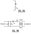
- the model of figure 11A can be used in order to simulate a circuit in which the coil is incorporated, i.e. a series connection of an inductance L and the loss resistance R LS .
- the voltage value is preferably calculated as an average making use of the measurements of the first quantity.
- said first part of the period is the part in which the coil is charged, and this first part has a duration t on .
- the DC to DC converter further comprises a second switching element, typically a diode, in particular a Schottky or fast reverse recovery diode, or an active switching element such as a transistor.
- the DC to DC converter is preferably one of the following: a buck converter, boost converter, buck-boost converter, non-inverting buck-boost converter, serial or parallel resonant converter, fly-back converter, full or half bridge buck converter. Note that this list is not exhaustive and that variants hereof also fall within the scope of the invention. Any DC to DC converter in which a coil can be incorporated such that the voltage across the coil changes in controllable manner will in principle be suitable for the present invention. The skilled person will further appreciate that the present invention can also be applied for the purpose of modelling one or more coils of a transformer, and/or for modelling the behaviour of a transformer or of coupled coils.
- the coil is incorporated such that for a part of the period the voltage across the coil is substantially equal to the difference between the input voltage and the output voltage.
- the input voltage will in this way influence the voltage across the coil during this part of the period, and the input voltage thus forms one of the parameters which can be varied in order to characterize the coil.
- the first switching element is preferably incorporated such that the voltage across the coil varies with the same frequency and duty cycle as the signal with which the first switching element is controlled.
- the first switching element can for instance be connected between an input terminal of the DC to DC converter and the coil.
- an input capacitor is preferably connected between the input terminals of the DC to DC converter and an output capacitor between the output terminals of the DC to DC converter.
- the present invention also relates to a storage medium for storing computer instructions for performing one or more steps of an embodiment of the method of the invention.
- the computer instructions can for instance thus comprise instructions for determining a voltage value for the voltage across the coil on the basis of the measured first quantity, determining at least one current value for the current through the coil on the basis of the measured second quantity and calculating a loss power and/or loss resistance and/or inductance of the coil on the basis of the at least one voltage value and the at least one current value.
- These instructions preferably calculate a loss resistance and/or loss power and/or induction in one of the above described ways.
- the system comprises a DC to DC converter with at least a first switching element and the coil to be modelled incorporated therein.
- a resistive load is connected between the output terminals of the converter.
- a voltage source for providing an input voltage at the input terminals of the converter
- control means for controlling the first switching element according to a frequency and duty cycle in order to obtain a voltage across the coil varying periodically in time
- first measuring means for measuring a first quantity representative of the voltage across the coil
- second measuring means for measuring a second quantity representative of the current through the coil
- computer means for determining at least one voltage value for the voltage across the coil on the basis of the measured first quantity; for determining at least one current value for the current through the coil on the basis of the measured second quantity; and for calculating a loss resistance and/or loss power and/or inductance of the coil on the basis of the at least one voltage value and the at least one current value.
- system is further adapted to perform one or more of the calculation steps described in the method claims and/or the DC to DC converter is provided with one or more of the measures described in the method claims.
- the system comprises a DC to DC converter 1 with a first switching element 2.
- the coil 3 to be modelled is incorporated into the DC to DC converter 1.
- Converter 1 has input terminals 4a, 4b and output terminals 5a, 5b. Connected between output terminals 5a, 5b is a resistive load 6 with an adjustable resistor R L . Further provided is an adjustable voltage source 7 for the purpose of providing an input voltage U in at input terminals 4a, 4b of the converter.
- Control means (not shown) are further provided for the purpose of providing a signal ⁇ for controlling the first switching element 2 at a frequency f sw and a duty cycle ⁇ .
- the limits must be determined for the input parameters U in , f sw , ⁇ and R L in order to define the measurement range, see step 20 of figure 2 .
- a value is set for U in , f sw and 5 on the basis of the defined measurement range, and the resistance R L of the load is set in a second step 22.
- Verification then takes place of whether the converter circuit is operating in a Discontinuous Current Mode (DCM) or in a Continuous Current Mode (CCM).
- DCM Discontinuous Current Mode
- CCM Continuous Current Mode
- measurements are performed only in the CCM mode. If it is determined that the circuit is in a DCM mode, the input parameters are modified in steps 21 and/or 22. Note however that it is also possible to apply the method according to the invention when the converter is in a DCM mode.
- the input parameters are modified in steps 21 and/or 22.
- the skilled person will appreciate that it is possible to proceed in many different ways here, and can for instance first vary the input voltage U in , while the other input parameters f sw , ⁇ and R L are kept constant, after which f sw and/or ⁇ can be varied and finally R L .
- Other sequences can of course also be envisaged.
- the DC to DC converter is a buck converter.
- the first switching element 102 is connected between an input terminal 104a and a first terminal of coil 103.
- Coil 103 is connected in series to the first switching element 102.
- the other terminal of coil 103 is connected via current measuring means 108b to an output terminal 105a.
- a second switching element in the form of a Schottky diode 110 is further connected between the one terminal of coil 103 and input terminal 104b.
- Voltage measuring means 108a are also provided for measuring the voltage u L across the coil.
- An input capacitor C dec is connected between the input terminals 104a, 104b.
- An output capacitor C out is connected between output terminals 105a, 105b.
- additional measuring means 111, 112, 113 can be provided for the purpose of measuring respectively the output voltage u out , the output current i out , the input current I in and the input voltage U in in order to verify the other measurements.
- FIG. 4 illustrates schematically typical measurement results for i L and u L as a function of time.
- This schematic graph shows a linear current progression, while the skilled person will appreciate that this progression is typically exponential.
- the voltage progression is further shown schematically as a block wave, and the skilled person will appreciate that the voltage across the coil is not wholly constant during charging (t on ) and discharging (t off ) of the coil.
- the current i L through the coil varies between a minimum value I min and a maximum value I max .
- I min minimum value
- I max maximum value
- the measuring means 108 for measuring the current through the coil are connected in series to the coil.
- Figures 5-10 show a number of other possible measurement setups which can be used in an embodiment of the method according to the invention.
- Figure 5 illustrates a boost converter, figure 6 a buck-boost converter, figure 7 a non-inverting buck-boost converter and figure 8 a series resonant converter. Since the measurement and calculation principles are similar to those described with reference to figure 2 , they will not be further elucidated.
- FIGS 9 and 10 illustrate two further alternative measurement setups which can for instance be used to characterize transformers.
- Figure 9 illustrates a fly-back converter and figure 10 a full bridge buck converter. In both circuits the voltage U L1 across the primary winding as well as the voltage U L2 across the secondary winding are measured. In addition, the current I L1 through the primary winding and the current I L2 through the secondary winding are measured. Note that in the circuit of figure 10 two identical windings are connected in series. Since these windings are identical, it suffices to measure the current through one of these windings and the voltage across one of these windings.
- Figure 11B illustrates a possible model for a transformer in which all losses of the transformer are modelled on the primary side.
- the model further comprises a magnetization inductance L M as a result of the finite permeability of the core material of the transformer, a loss resistance R M as a result of the core, i.e. as a result of the so-called iron losses, an equivalent leakage inductance L eq as a result of the finite coupling between the primary and the secondary winding, and an equivalent loss resistance R eq as a result of the serial resistance of the primary and secondary windings.
Landscapes
- Engineering & Computer Science (AREA)
- Physics & Mathematics (AREA)
- Computer Hardware Design (AREA)
- General Physics & Mathematics (AREA)
- Theoretical Computer Science (AREA)
- Microelectronics & Electronic Packaging (AREA)
- Evolutionary Computation (AREA)
- Geometry (AREA)
- General Engineering & Computer Science (AREA)
- Power Engineering (AREA)
- Dc-Dc Converters (AREA)
Claims (15)
- Verfahren zur Berechnung von Modellparametern für wenigstens eine zu modellierende Spule, wobei das Verfahren die folgenden Schritte aufweist:- Aufnehmen der wenigstens einen zu modellierenden Spule in einen Gleichstrom-Gleichstrom-Wandler mit wenigstens einem ersten Schaltelement, wobei der Wandler Eingangsanschlüsse und Ausgangsanschlüsse hat;- Schalten einer Widerstandslast zwischen die Ausgangsanschlüsse des Gleichstrom-Gleichstrom-Wandlers;- Anlegen einer Eingangsspannung an die Eingangsanschlüsse des Wandlers;- Steuern des ersten Schaltelements gemäß einer Frequenz und einem Tastverhältnis, um eine Spannung an einer Spule der wenigstens einen zu modellierenden Spule zu erhalten, die zeitlich periodisch variiert, wobei die Spannung wenigstens in einem Teil einer Periode von der Eingangsspannung abhängt;- Messen wenigstens einer ersten Größe, die die Spannung an der Spule zu aufeinanderfolgenden Zeitpunkten wenigstens in dem genannten Teil einer Periode darstellt;- Messen wenigstens einer zweiten Größe, die den Strom durch die Spule zu aufeinanderfolgenden Zeitpunkten wenigstens in dem genannten Teil einer Periode darstellt;- Bestimmen wenigstens eines Spannungswerts für die Spannung an der Spule auf der Basis der gemessenen ersten Größe;- Bestimmen wenigstens eines Stromwerts für den Strom durch die Spule auf der Basis der gemessenen zweiten Größe;- Berechnen eines Verlustwiderstands und/oder einer Verlustleistung der Spule auf der Basis des wenigstens einen Spannungswerts und des wenigstens einen Stromwerts;- Bestimmen wenigstens eines ersten und zweiten Stromwerts für den Strom durch die Spule jeweils zu einem ersten und zweiten Zeitpunkt der aufeinanderfolgenden Zeitpunkte in dem genannten Teil der Periode auf der Basis der gemessenen zweiten Größe;- Berechnen einer Induktivität der Spule auf der Basis des Spannungswerts, des Verlustwiderstands oder der Verlustleistung und wenigstens der ersten und zweiten Stromwerte;- Wiederholen der vorstehend dargelegten Schritte für eine andere Eingangsspannung und/oder für eine andere Frequenz und/oder für ein anderes Tastverhältnis und/oder für eine andere Widerstandslast.
- Verfahren nach Anspruch 1, wobei die aufeinanderfolgenden Zeitpunkte im Wesentlichen eine vollständige Periode abdecken.
- Verfahren nach einem der vorangehenden Ansprüche, wobei die Verlustleistung als ein Mittel des Produkts der Spannung an der Spule und dem Strom durch die Spule basierend auf den Messungen der ersten und zweiten Größen zu den aufeinanderfolgenden Zeitpunkten berechnet wird, wobei die aufeinanderfolgenden Zeitpunkte vorzugsweise im Wesentlichen eine vollständige Periode abdecken.
- Verfahren nach einem der vorangehenden Ansprüche, wobei der Verlustwiderstand als der Quotient der Verlustleistung und dem Quadrat eines effektiven Stroms durch die Spule berechnet wird, wobei der effektive Strom auf der Basis der Messungen der zweiten Größe und vorzugsweise auf der Basis der ersten und zweiten Stromwerte berechnet wird.
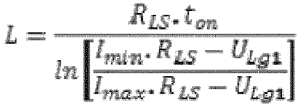
- Verfahren nach den Ansprüchen 1 und 4, dadurch gekennzeichnet, dass die Induktivität berechnet wird als
- Verfahren nach einem der vorangehenden Ansprüche, dadurch gekennzeichnet, dass der Spannungswert als ein Mittel unter Verwendung der Messungen der ersten Größe berechnet wird.
- Verfahren nach Anspruch 6, wobei der Spannungswert berechnet wird als

- Verfahren nach einem der vorangehenden Ansprüche, dadurch gekennzeichnet, dass der erste Teil der Periode der Teil ist, in dem die Spule aufgeladen wird, und dass dieser Teil eine Dauer ton hat.
- Verfahren nach einem der vorangehenden Ansprüche, wobei der Gleichstrom-Gleichstrom-Wandler ferner ein zweites Schaltelement aufweist.
- Verfahren nach einem der vorangehenden Ansprüche, wobei der Gleichstrom-Gleichstrom-Wandler einer der Folgenden ist: ein Abwärtswandler, ein Aufwärtswandler, ein Tief-Hochsetzsteller, ein nicht invertierender Tief-Hochsetzsteller, ein Reihen- oder Parallelresonanzwandler, ein Sperrwandler, ein Voll- oder Halbbrücken-Aufwärtswandler.
- Verfahren nach einem der vorangehenden Ansprüche, wobei es eine Ausgangsspannung an der Widerstandslast gibt und die Spule derart aufgenommen ist, dass die Spannung an der Spule in einem Teil der Periode im Wesentlichen gleich der Differenz zwischen der Eingangsspannung und der Ausgangsspannung ist.
- Verfahren nach einem der vorangehenden Ansprüche, wobei das erste Schaltelement zwischen einen Eingangsanschluss des Gleichstrom-Gleichstrom-Wandlers und die Spule geschaltet ist.
- Verfahren nach einem der vorangehenden Ansprüche, wobei die wenigstens eine Spule einen Teil eines Transformators mit einer ersten Spule und einer zweiten Spule bildet, wobei die Messung der wenigstens einen ersten Größe besteht aus:- Messen wenigstens einer ersten Größe, die die Spannung an der ersten Spule darstellt; und- Messen wenigstens einer ersten Größe, die die Spannung an der zweiten Spule darstellt;wobei die Messung der wenigstens einen zweiten Größe besteht aus:- Messen wenigstens einer zweiten Größe, die den Strom durch die erste Spule darstellt; und- Messen wenigstens einer zweiten Größe, die den Strom durch die zweite Spule darstellt;wobei die Bestimmung des wenigstens einen Spannungswerts besteht aus:- Bestimmen wenigstens eines Spannungswerts für die Spannung an der ersten Spule auf der Basis der gemessenen ersten Größe; und- Bestimmen wenigstens eines Spannungswerts für die Spannung an der zweiten Spule auf der Basis der gemessenen ersten Größe;wobei die Bestimmung des wenigstens einen Stromwerts besteht aus:- Bestimmen wenigstens eines Stromwerts für den Strom durch die erste Spule auf der Basis der gemessenen zweiten Größe; und- Bestimmen wenigstens eines Stromwerts für den Strom durch die zweite Spule auf der Basis der gemessenen zweiten Größe;wobei die Berechnung eines Verlustwiderstands und/oder einer Verlustleistung besteht aus:- Berechnen einer Magnetisierungsinduktivität und eines Magnetisierungsverlustwiderstands auf der Basis des wenigstens einen Spannungswerts für die erste und zweite Spule und des wenigstens einen Stromwerts für die erste und zweite Spule;- Berechnen einer äquivalenten Streuinduktivität und eines äquivalenten Verlustwiderstands auf der Basis des wenigstens einen Spannungswerts für die erste und zweite Spule und des wenigstens einen Stromwerts für die erste und zweite Spule.
- Speichermedium, auf dem Computeranweisungen gespeichert werden, um das Verfahren nach einem der vorangehenden Ansprüche auf einem System nach Anspruch 15 durchzuführen.
- System zur Berechnung von Modellparametern für wenigstens eine zu modellierende Spule nach dem Verfahren von Anspruch 1, wobei das System aufweist:- einen Gleichstrom-Gleichstrom-Wandler mit wenigstens einem ersten Schaltelement und wenigstens einer zu modellierenden Spule, die darin aufgenommen sind; wobei der Wandler Eingangsanschlüsse und Ausgangsanschlüsse hat;- eine Widerstandslast zwischen den Ausgangsanschlüssen des Wandlers;- eine Spannungsquelle, die zu dem Zweck angeschlossen ist, eine Eingangsspannung an die Eingangsanschlüsse des Wandlers bereitzustellen;- Steuereinrichtungen zum Steuern des ersten Schaltelements gemäß einer Sollfrequenz und einem Tastverhältnis, um eine Spannung an der Spule der wenigstens einen zu modellierenden Spule zu erhalten, die zeitlich periodisch variiert, so dass die Spannung wenigstens in einem Teil einer Periode von der Eingangsspannung abhängt;- eine erste Messeinrichtung zum Messen wenigstens einer ersten Größe, die die Spannung an der Spule zu aufeinanderfolgenden Zeitpunkten wenigstens in dem genannten Teil einer Periode darstellt;- eine zweite Messeinrichtung zum Messen wenigstens einer zweiten Größe, die den Strom durch die Spule zu aufeinanderfolgenden Zeitpunkten wenigstens in dem genannten Teil einer Periode darstellt;- Computereinrichtungen zum Bestimmen wenigstens eines Spannungswerts für die Spannung an der Spule auf der Basis der gemessenen ersten Größe; zum Bestimmen wenigstens eines Stromwerts für den Strom durch die Spule auf der Basis der gemessenen zweiten Größe; und zum Berechnen eines Verlustwiderstands und/oder einer Verlustleistung der Spule auf der Basis des wenigstens einen Spannungswerts und des wenigstens einen Stromwerts; wobei die Computereinrichtungen ferner geeignet sind, um wenigstens einen ersten und zweiten Stromwert für den Strom durch die Spule jeweils zu einem ersten und zweiten Zeitpunkt der aufeinanderfolgenden Zeitpunkte in dem genannten Teil der Periode auf der Basis der gemessenen zweiten Größe zu bestimmen; und eine Induktivität der Spule auf der Basis des Spannungswerts, des Verlustwiderstands oder der Verlustleistung und wenigstens der ersten und zweiten Stromwerte zu berechnen.
Applications Claiming Priority (2)
| Application Number | Priority Date | Filing Date | Title |
|---|---|---|---|
| BE2012/0054A BE1020014A5 (nl) | 2012-01-27 | 2012-01-27 | Werkwijzen en systeem voor het berekenen van modelparameters voor een te modelleren spoel. |
| PCT/BE2013/000001 WO2013110145A1 (en) | 2012-01-27 | 2013-01-08 | Method and system for calculating model parameters for a coil to be modelled |
Publications (3)
| Publication Number | Publication Date |
|---|---|
| EP2807589A1 EP2807589A1 (de) | 2014-12-03 |
| EP2807589B1 true EP2807589B1 (de) | 2018-03-07 |
| EP2807589B8 EP2807589B8 (de) | 2018-04-18 |
Family
ID=45922616
Family Applications (1)
| Application Number | Title | Priority Date | Filing Date |
|---|---|---|---|
| EP13709299.5A Active EP2807589B8 (de) | 2012-01-27 | 2013-01-08 | Verfahren und vorrichtung zur berechnung der modellparameter einer zu modellierenden spule |
Country Status (4)
| Country | Link |
|---|---|
| US (1) | US10901015B2 (de) |
| EP (1) | EP2807589B8 (de) |
| BE (1) | BE1020014A5 (de) |
| WO (1) | WO2013110145A1 (de) |
Cited By (2)
| Publication number | Priority date | Publication date | Assignee | Title |
|---|---|---|---|---|
| IT202000026599A1 (it) | 2020-11-06 | 2022-05-06 | Ipera S R L | Metodo, stazione di misurazione e sistema di determinazione del comportamento di un componente elettrico o elettronico di potenza |
| EP4549961A1 (de) * | 2023-10-31 | 2025-05-07 | Abb Schweiz Ag | Verfahren zur bestimmung der leckimpedanz eines transformators und elektrischer leistungswandler |
Families Citing this family (10)
| Publication number | Priority date | Publication date | Assignee | Title |
|---|---|---|---|---|
| WO2015082440A1 (en) | 2013-12-02 | 2015-06-11 | Dsm Ip Assets B.V. | Rod core inductors |
| BE1022933B1 (nl) * | 2014-11-07 | 2016-10-20 | Mindcet Bvba | Werkwijze en systeem voor het berekenen van modelparameters voor een te modelleren condensator |
| CN104635018A (zh) * | 2015-02-15 | 2015-05-20 | 中国电力工程顾问集团中南电力设计院有限公司 | 基于等效电路模型的海底电缆载流量计算方法 |
| CN106154040B (zh) * | 2015-03-24 | 2019-09-06 | 国家电网公司 | 一种用于计算电网单点等值时等效谐波阻抗方法 |
| DE102016103075A1 (de) * | 2016-02-22 | 2017-08-24 | Knorr-Bremse Systeme für Nutzfahrzeuge GmbH | Verfahren und vorrichtung zum messen zumindest einer eigenschaft einer spule, verfahren und vorrichtung zum messen der position eines betätigungsglieds, sowie kraftfahrzeug |
| CN106339535A (zh) * | 2016-08-20 | 2017-01-18 | 哈尔滨锅炉厂有限责任公司 | U型管式换热器内置节流孔板孔径的计算方法 |
| CN113271061B (zh) * | 2021-04-21 | 2023-02-10 | 华为数字能源技术有限公司 | 一种光伏系统、功率变换器及测量电感感值的方法 |
| CN113341202B (zh) * | 2021-06-09 | 2023-09-26 | 国网陕西省电力公司电力科学研究院 | 一种用于消弧线圈电容电流测量精度检测的方法及系统 |
| CN113761793B (zh) * | 2021-08-16 | 2024-02-27 | 固德威技术股份有限公司 | 逆变器输出阻抗检测装置及方法、逆变器运行控制方法 |
| CN115963326B (zh) * | 2023-02-03 | 2025-08-05 | 国网河北省电力有限公司沧州供电分公司 | 一种软磁材料铁心损耗检测方法 |
Family Cites Families (17)
| Publication number | Priority date | Publication date | Assignee | Title |
|---|---|---|---|---|
| US3173053A (en) * | 1960-08-05 | 1965-03-09 | Bendix Corp | Transistorized rotating field ppi deflection system |
| US4032836A (en) * | 1975-11-28 | 1977-06-28 | The Gillette Company | Transformer circuit |
| US6321169B1 (en) * | 1998-02-27 | 2001-11-20 | Taiyo Yuden Co., Ltd. | Equivalent circuit of inductance element, method of analyzing circuit constants, simulator, and record media |
| JP3776752B2 (ja) * | 2001-06-07 | 2006-05-17 | 新電元工業株式会社 | Dc−dcコンバータ |
| US6876936B2 (en) * | 2003-07-25 | 2005-04-05 | Tektronix, Inc. | Measurement of inductance using a digital storage oscilloscope under real-time operating environments |
| US6856127B1 (en) * | 2003-07-25 | 2005-02-15 | Tektronix, Inc. | Oscilloscope-based automatic finder for locating high power dissipation areas in switch-mode power supply (SMPS) switching devices |
| US7222034B2 (en) * | 2003-09-19 | 2007-05-22 | Tektronix, Inc. | In-circuit measurement of saturation flux density Bsat, coercivity Hc, and permiability of magnetic components using a digital storage oscilloscope |
| KR100597415B1 (ko) * | 2004-12-16 | 2006-07-05 | 삼성전자주식회사 | 가변저항 조절에 의해 개선된 스위칭 동작을 수행하는동기 정류형 직류/직류 컨버터 |
| US7990120B2 (en) * | 2006-08-04 | 2011-08-02 | Linear Technology Corporation | Circuits and methods for adjustable peak inductor current and hysteresis for burst mode in switching regulators |
| US7944153B2 (en) * | 2006-12-15 | 2011-05-17 | Intersil Americas Inc. | Constant current light emitting diode (LED) driver circuit and method |
| US7969694B2 (en) * | 2008-08-13 | 2011-06-28 | Infineon Technologies Ag | Diode loss detection for low side MOSFET of a synchronous output stage |
| WO2010095078A2 (en) * | 2009-02-19 | 2010-08-26 | Koninklijke Philips Electronics N. V. | Output current sensing method in discontinuous dc-to-dc voltage converter |
| US9106201B1 (en) * | 2010-06-23 | 2015-08-11 | Volterra Semiconductor Corporation | Systems and methods for DC-to-DC converter control |
| EP2432107B1 (de) * | 2010-09-15 | 2013-10-23 | Nxp B.V. | Gleichspannungswandler mit einem Eingang und mehreren Ausgängen |
| US8482268B2 (en) * | 2010-09-16 | 2013-07-09 | System General Corporation | Correction circuit of a switching-current sample for power converters in both CCM and DCM operation |
| CN104221209B (zh) * | 2010-12-03 | 2016-10-26 | 晨星公司 | 具有带反向mosfet的降压转换器的光伏系统充电控制器 |
| US8736246B2 (en) * | 2011-09-22 | 2014-05-27 | Acbel Polytech Inc. | Power factor control circuit and power factor control method |
-
2012
- 2012-01-27 BE BE2012/0054A patent/BE1020014A5/nl active
-
2013
- 2013-01-08 WO PCT/BE2013/000001 patent/WO2013110145A1/en not_active Ceased
- 2013-01-08 US US14/372,815 patent/US10901015B2/en active Active
- 2013-01-08 EP EP13709299.5A patent/EP2807589B8/de active Active
Cited By (2)
| Publication number | Priority date | Publication date | Assignee | Title |
|---|---|---|---|---|
| IT202000026599A1 (it) | 2020-11-06 | 2022-05-06 | Ipera S R L | Metodo, stazione di misurazione e sistema di determinazione del comportamento di un componente elettrico o elettronico di potenza |
| EP4549961A1 (de) * | 2023-10-31 | 2025-05-07 | Abb Schweiz Ag | Verfahren zur bestimmung der leckimpedanz eines transformators und elektrischer leistungswandler |
Also Published As
| Publication number | Publication date |
|---|---|
| EP2807589B8 (de) | 2018-04-18 |
| EP2807589A1 (de) | 2014-12-03 |
| WO2013110145A1 (en) | 2013-08-01 |
| US10901015B2 (en) | 2021-01-26 |
| BE1020014A5 (nl) | 2013-03-05 |
| US20140372059A1 (en) | 2014-12-18 |
Similar Documents
| Publication | Publication Date | Title |
|---|---|---|
| US10901015B2 (en) | Method and system for calculating model parameters for a coil to be modelled | |
| EP3018813B1 (de) | Verfahren und system zur berechnung von modellparametern für einen zu modellierenden kondensator | |
| Foo et al. | A step-by-step guide to extracting winding resistance from an impedance measurement | |
| Stenglein et al. | Core loss model for arbitrary excitations with DC bias covering a wide frequency range | |
| CN107703368B (zh) | 一种变压器深度饱和状态下的电感的测量方法 | |
| CN107947592B (zh) | 一种基于路耦合的全桥式开关电源纹波系数预测方法 | |
| CN102915059A (zh) | 提供关于电子负载的可变电抗性负载能力的手段 | |
| CN116046191A (zh) | 一种测温装置、测温方法和气溶胶生成设备 | |
| Stenglein et al. | Novel fit formula for the calculation of hysteresis losses including DC-premagnetization | |
| Ravera et al. | A nonlinear behavioral model of a ferrite-core inductor with fixed-frequency sinusoidal voltage input | |
| Stenglein et al. | Influence of magnetic history and accommodation on hysteresis loss for arbitrary core excitations | |
| Hlavacek et al. | The Rogowski coil design software | |
| Faba et al. | Measurements of magnetic characteristics of laminated Fe-Si steel filter inductors in grid interface converters | |
| Nutwong et al. | Load monitoring and output voltage control for SP topology IPT system using a single-side controller without any output measurement | |
| CN113654678A (zh) | 一种加热测温电路及其测温方法、烹饪装置、存储介质 | |
| Sato et al. | Study on an accurate iron loss calculation method considering the non-uniformity of the magnetic flux density | |
| Zhang et al. | Estimating switching loss and core loss in dual active bridge DC-DC converters | |
| CN114158149B (zh) | 电磁炉功率估算方法、装置、电磁炉及存储介质 | |
| Stenglein et al. | Novel gan half-bridge configuration for the measurement of core losses under rectangular voltages and dc-bias | |
| Joshi et al. | Estimation of core loss of high frequency nanocrystalline transformer for non-sinusoidal excitation | |
| CN105528506B (zh) | 一种饱和电抗器等值电路模型的参数获取方法 | |
| Bramanpalli | Accurate calculation of AC losses of inductors in power electronic applications | |
| CN223139712U (zh) | 一种直流偏置电感感值测试电路 | |
| Note | Selecting IHLP composite inductors for non-isolated converters utilizing Vishay’s application sheet | |
| CN119689353B (zh) | 一种基于磁动势的变压器剩磁测量方法 |
Legal Events
| Date | Code | Title | Description |
|---|---|---|---|
| PUAI | Public reference made under article 153(3) epc to a published international application that has entered the european phase |
Free format text: ORIGINAL CODE: 0009012 |
|
| 17P | Request for examination filed |
Effective date: 20140813 |
|
| AK | Designated contracting states |
Kind code of ref document: A1 Designated state(s): AL AT BE BG CH CY CZ DE DK EE ES FI FR GB GR HR HU IE IS IT LI LT LU LV MC MK MT NL NO PL PT RO RS SE SI SK SM TR |
|
| DAX | Request for extension of the european patent (deleted) | ||
| REG | Reference to a national code |
Ref country code: DE Ref legal event code: R079 Ref document number: 602013033994 Country of ref document: DE Free format text: PREVIOUS MAIN CLASS: G06F0017500000 Ipc: G01R0019000000 |
|
| RIC1 | Information provided on ipc code assigned before grant |
Ipc: G01R 27/26 20060101ALN20170703BHEP Ipc: G01R 27/08 20060101ALI20170703BHEP Ipc: G06F 17/50 20060101ALI20170703BHEP Ipc: G01R 21/133 20060101ALI20170703BHEP Ipc: G01R 19/00 20060101AFI20170703BHEP |
|
| GRAP | Despatch of communication of intention to grant a patent |
Free format text: ORIGINAL CODE: EPIDOSNIGR1 |
|
| STAA | Information on the status of an ep patent application or granted ep patent |
Free format text: STATUS: GRANT OF PATENT IS INTENDED |
|
| INTG | Intention to grant announced |
Effective date: 20170811 |
|
| GRAS | Grant fee paid |
Free format text: ORIGINAL CODE: EPIDOSNIGR3 |
|
| GRAA | (expected) grant |
Free format text: ORIGINAL CODE: 0009210 |
|
| STAA | Information on the status of an ep patent application or granted ep patent |
Free format text: STATUS: THE PATENT HAS BEEN GRANTED |
|
| AK | Designated contracting states |
Kind code of ref document: B1 Designated state(s): AL AT BE BG CH CY CZ DE DK EE ES FI FR GB GR HR HU IE IS IT LI LT LU LV MC MK MT NL NO PL PT RO RS SE SI SK SM TR |
|
| REG | Reference to a national code |
Ref country code: GB Ref legal event code: FG4D |
|
| REG | Reference to a national code |
Ref country code: CH Ref legal event code: EP Ref country code: AT Ref legal event code: REF Ref document number: 977136 Country of ref document: AT Kind code of ref document: T Effective date: 20180315 |
|
| RAP2 | Party data changed (patent owner data changed or rights of a patent transferred) |
Owner name: MINDCET NV |
|
| REG | Reference to a national code |
Ref country code: IE Ref legal event code: FG4D |
|
| REG | Reference to a national code |
Ref country code: DE Ref legal event code: R096 Ref document number: 602013033994 Country of ref document: DE |
|
| REG | Reference to a national code |
Ref country code: NL Ref legal event code: FP |
|
| REG | Reference to a national code |
Ref country code: LT Ref legal event code: MG4D Ref country code: BE Ref legal event code: PD Owner name: MINDCET NV; BE Free format text: DETAILS ASSIGNMENT: CHANGE OF OWNER(S), CHANGEMENT DE FORME JURIDIQUE, + ADRESSE; FORMER OWNER NAME: MINDCET BVBA Effective date: 20180522 |
|
| PG25 | Lapsed in a contracting state [announced via postgrant information from national office to epo] |
Ref country code: CY Free format text: LAPSE BECAUSE OF FAILURE TO SUBMIT A TRANSLATION OF THE DESCRIPTION OR TO PAY THE FEE WITHIN THE PRESCRIBED TIME-LIMIT Effective date: 20180307 Ref country code: LT Free format text: LAPSE BECAUSE OF FAILURE TO SUBMIT A TRANSLATION OF THE DESCRIPTION OR TO PAY THE FEE WITHIN THE PRESCRIBED TIME-LIMIT Effective date: 20180307 Ref country code: FI Free format text: LAPSE BECAUSE OF FAILURE TO SUBMIT A TRANSLATION OF THE DESCRIPTION OR TO PAY THE FEE WITHIN THE PRESCRIBED TIME-LIMIT Effective date: 20180307 Ref country code: NO Free format text: LAPSE BECAUSE OF FAILURE TO SUBMIT A TRANSLATION OF THE DESCRIPTION OR TO PAY THE FEE WITHIN THE PRESCRIBED TIME-LIMIT Effective date: 20180607 Ref country code: ES Free format text: LAPSE BECAUSE OF FAILURE TO SUBMIT A TRANSLATION OF THE DESCRIPTION OR TO PAY THE FEE WITHIN THE PRESCRIBED TIME-LIMIT Effective date: 20180307 Ref country code: HR Free format text: LAPSE BECAUSE OF FAILURE TO SUBMIT A TRANSLATION OF THE DESCRIPTION OR TO PAY THE FEE WITHIN THE PRESCRIBED TIME-LIMIT Effective date: 20180307 |
|
| REG | Reference to a national code |
Ref country code: AT Ref legal event code: MK05 Ref document number: 977136 Country of ref document: AT Kind code of ref document: T Effective date: 20180307 |
|
| PG25 | Lapsed in a contracting state [announced via postgrant information from national office to epo] |
Ref country code: RS Free format text: LAPSE BECAUSE OF FAILURE TO SUBMIT A TRANSLATION OF THE DESCRIPTION OR TO PAY THE FEE WITHIN THE PRESCRIBED TIME-LIMIT Effective date: 20180307 Ref country code: SE Free format text: LAPSE BECAUSE OF FAILURE TO SUBMIT A TRANSLATION OF THE DESCRIPTION OR TO PAY THE FEE WITHIN THE PRESCRIBED TIME-LIMIT Effective date: 20180307 Ref country code: LV Free format text: LAPSE BECAUSE OF FAILURE TO SUBMIT A TRANSLATION OF THE DESCRIPTION OR TO PAY THE FEE WITHIN THE PRESCRIBED TIME-LIMIT Effective date: 20180307 Ref country code: BG Free format text: LAPSE BECAUSE OF FAILURE TO SUBMIT A TRANSLATION OF THE DESCRIPTION OR TO PAY THE FEE WITHIN THE PRESCRIBED TIME-LIMIT Effective date: 20180607 Ref country code: GR Free format text: LAPSE BECAUSE OF FAILURE TO SUBMIT A TRANSLATION OF THE DESCRIPTION OR TO PAY THE FEE WITHIN THE PRESCRIBED TIME-LIMIT Effective date: 20180608 |
|
| PG25 | Lapsed in a contracting state [announced via postgrant information from national office to epo] |
Ref country code: PL Free format text: LAPSE BECAUSE OF FAILURE TO SUBMIT A TRANSLATION OF THE DESCRIPTION OR TO PAY THE FEE WITHIN THE PRESCRIBED TIME-LIMIT Effective date: 20180307 Ref country code: EE Free format text: LAPSE BECAUSE OF FAILURE TO SUBMIT A TRANSLATION OF THE DESCRIPTION OR TO PAY THE FEE WITHIN THE PRESCRIBED TIME-LIMIT Effective date: 20180307 Ref country code: RO Free format text: LAPSE BECAUSE OF FAILURE TO SUBMIT A TRANSLATION OF THE DESCRIPTION OR TO PAY THE FEE WITHIN THE PRESCRIBED TIME-LIMIT Effective date: 20180307 Ref country code: AL Free format text: LAPSE BECAUSE OF FAILURE TO SUBMIT A TRANSLATION OF THE DESCRIPTION OR TO PAY THE FEE WITHIN THE PRESCRIBED TIME-LIMIT Effective date: 20180307 |
|
| PG25 | Lapsed in a contracting state [announced via postgrant information from national office to epo] |
Ref country code: SK Free format text: LAPSE BECAUSE OF FAILURE TO SUBMIT A TRANSLATION OF THE DESCRIPTION OR TO PAY THE FEE WITHIN THE PRESCRIBED TIME-LIMIT Effective date: 20180307 Ref country code: SM Free format text: LAPSE BECAUSE OF FAILURE TO SUBMIT A TRANSLATION OF THE DESCRIPTION OR TO PAY THE FEE WITHIN THE PRESCRIBED TIME-LIMIT Effective date: 20180307 Ref country code: AT Free format text: LAPSE BECAUSE OF FAILURE TO SUBMIT A TRANSLATION OF THE DESCRIPTION OR TO PAY THE FEE WITHIN THE PRESCRIBED TIME-LIMIT Effective date: 20180307 Ref country code: CZ Free format text: LAPSE BECAUSE OF FAILURE TO SUBMIT A TRANSLATION OF THE DESCRIPTION OR TO PAY THE FEE WITHIN THE PRESCRIBED TIME-LIMIT Effective date: 20180307 |
|
| REG | Reference to a national code |
Ref country code: DE Ref legal event code: R097 Ref document number: 602013033994 Country of ref document: DE |
|
| PG25 | Lapsed in a contracting state [announced via postgrant information from national office to epo] |
Ref country code: PT Free format text: LAPSE BECAUSE OF FAILURE TO SUBMIT A TRANSLATION OF THE DESCRIPTION OR TO PAY THE FEE WITHIN THE PRESCRIBED TIME-LIMIT Effective date: 20180709 |
|
| PLBE | No opposition filed within time limit |
Free format text: ORIGINAL CODE: 0009261 |
|
| STAA | Information on the status of an ep patent application or granted ep patent |
Free format text: STATUS: NO OPPOSITION FILED WITHIN TIME LIMIT |
|
| PG25 | Lapsed in a contracting state [announced via postgrant information from national office to epo] |
Ref country code: DK Free format text: LAPSE BECAUSE OF FAILURE TO SUBMIT A TRANSLATION OF THE DESCRIPTION OR TO PAY THE FEE WITHIN THE PRESCRIBED TIME-LIMIT Effective date: 20180307 |
|
| 26N | No opposition filed |
Effective date: 20181210 |
|
| PG25 | Lapsed in a contracting state [announced via postgrant information from national office to epo] |
Ref country code: SI Free format text: LAPSE BECAUSE OF FAILURE TO SUBMIT A TRANSLATION OF THE DESCRIPTION OR TO PAY THE FEE WITHIN THE PRESCRIBED TIME-LIMIT Effective date: 20180307 Ref country code: IT Free format text: LAPSE BECAUSE OF FAILURE TO SUBMIT A TRANSLATION OF THE DESCRIPTION OR TO PAY THE FEE WITHIN THE PRESCRIBED TIME-LIMIT Effective date: 20180307 |
|
| PG25 | Lapsed in a contracting state [announced via postgrant information from national office to epo] |
Ref country code: MC Free format text: LAPSE BECAUSE OF FAILURE TO SUBMIT A TRANSLATION OF THE DESCRIPTION OR TO PAY THE FEE WITHIN THE PRESCRIBED TIME-LIMIT Effective date: 20180307 |
|
| REG | Reference to a national code |
Ref country code: CH Ref legal event code: PL |
|
| PG25 | Lapsed in a contracting state [announced via postgrant information from national office to epo] |
Ref country code: LU Free format text: LAPSE BECAUSE OF NON-PAYMENT OF DUE FEES Effective date: 20190108 |
|
| REG | Reference to a national code |
Ref country code: IE Ref legal event code: MM4A |
|
| PG25 | Lapsed in a contracting state [announced via postgrant information from national office to epo] |
Ref country code: LI Free format text: LAPSE BECAUSE OF NON-PAYMENT OF DUE FEES Effective date: 20190131 Ref country code: CH Free format text: LAPSE BECAUSE OF NON-PAYMENT OF DUE FEES Effective date: 20190131 |
|
| PG25 | Lapsed in a contracting state [announced via postgrant information from national office to epo] |
Ref country code: IE Free format text: LAPSE BECAUSE OF NON-PAYMENT OF DUE FEES Effective date: 20190108 |
|
| PG25 | Lapsed in a contracting state [announced via postgrant information from national office to epo] |
Ref country code: TR Free format text: LAPSE BECAUSE OF FAILURE TO SUBMIT A TRANSLATION OF THE DESCRIPTION OR TO PAY THE FEE WITHIN THE PRESCRIBED TIME-LIMIT Effective date: 20180307 |
|
| PG25 | Lapsed in a contracting state [announced via postgrant information from national office to epo] |
Ref country code: MT Free format text: LAPSE BECAUSE OF NON-PAYMENT OF DUE FEES Effective date: 20190108 |
|
| PG25 | Lapsed in a contracting state [announced via postgrant information from national office to epo] |
Ref country code: IS Free format text: LAPSE BECAUSE OF FAILURE TO SUBMIT A TRANSLATION OF THE DESCRIPTION OR TO PAY THE FEE WITHIN THE PRESCRIBED TIME-LIMIT Effective date: 20180707 |
|
| PG25 | Lapsed in a contracting state [announced via postgrant information from national office to epo] |
Ref country code: HU Free format text: LAPSE BECAUSE OF FAILURE TO SUBMIT A TRANSLATION OF THE DESCRIPTION OR TO PAY THE FEE WITHIN THE PRESCRIBED TIME-LIMIT; INVALID AB INITIO Effective date: 20130108 |
|
| PG25 | Lapsed in a contracting state [announced via postgrant information from national office to epo] |
Ref country code: MK Free format text: LAPSE BECAUSE OF FAILURE TO SUBMIT A TRANSLATION OF THE DESCRIPTION OR TO PAY THE FEE WITHIN THE PRESCRIBED TIME-LIMIT Effective date: 20180307 |
|
| P01 | Opt-out of the competence of the unified patent court (upc) registered |
Effective date: 20230528 |
|
| PGFP | Annual fee paid to national office [announced via postgrant information from national office to epo] |
Ref country code: NL Payment date: 20260126 Year of fee payment: 14 |
|
| PGFP | Annual fee paid to national office [announced via postgrant information from national office to epo] |
Ref country code: GB Payment date: 20260127 Year of fee payment: 14 |
|
| PGFP | Annual fee paid to national office [announced via postgrant information from national office to epo] |
Ref country code: DE Payment date: 20260128 Year of fee payment: 14 |
|
| PGFP | Annual fee paid to national office [announced via postgrant information from national office to epo] |
Ref country code: BE Payment date: 20260127 Year of fee payment: 14 |
|
| PGFP | Annual fee paid to national office [announced via postgrant information from national office to epo] |
Ref country code: FR Payment date: 20260126 Year of fee payment: 14 |