EP2807500B1 - Dispositif de détection d'environnement et procédé correspondant pour la détermination de la position et/ou du déplacement d'un objet - Google Patents
Dispositif de détection d'environnement et procédé correspondant pour la détermination de la position et/ou du déplacement d'un objet Download PDFInfo
- Publication number
- EP2807500B1 EP2807500B1 EP12808719.4A EP12808719A EP2807500B1 EP 2807500 B1 EP2807500 B1 EP 2807500B1 EP 12808719 A EP12808719 A EP 12808719A EP 2807500 B1 EP2807500 B1 EP 2807500B1
- Authority
- EP
- European Patent Office
- Prior art keywords
- signal
- damping
- electroacoustic transducer
- environment sensing
- sensing apparatus
- Prior art date
- Legal status (The legal status is an assumption and is not a legal conclusion. Google has not performed a legal analysis and makes no representation as to the accuracy of the status listed.)
- Active
Links
- 238000000034 method Methods 0.000 title claims description 8
- 238000001514 detection method Methods 0.000 title description 24
- 238000013016 damping Methods 0.000 claims description 77
- 230000005540 biological transmission Effects 0.000 claims description 43
- 238000011156 evaluation Methods 0.000 claims description 42
- 230000003247 decreasing effect Effects 0.000 claims description 3
- 230000004044 response Effects 0.000 claims description 3
- 230000007423 decrease Effects 0.000 claims 2
- 238000010586 diagram Methods 0.000 description 19
- 239000003990 capacitor Substances 0.000 description 15
- 230000002238 attenuated effect Effects 0.000 description 8
- 230000008859 change Effects 0.000 description 6
- 230000008878 coupling Effects 0.000 description 6
- 238000010168 coupling process Methods 0.000 description 6
- 238000005859 coupling reaction Methods 0.000 description 6
- 230000003321 amplification Effects 0.000 description 5
- 230000001419 dependent effect Effects 0.000 description 5
- 238000003199 nucleic acid amplification method Methods 0.000 description 5
- 230000006378 damage Effects 0.000 description 4
- 230000002829 reductive effect Effects 0.000 description 4
- 230000000694 effects Effects 0.000 description 3
- 230000001681 protective effect Effects 0.000 description 3
- 238000002604 ultrasonography Methods 0.000 description 3
- 230000006835 compression Effects 0.000 description 2
- 238000007906 compression Methods 0.000 description 2
- 238000002592 echocardiography Methods 0.000 description 2
- 238000012544 monitoring process Methods 0.000 description 2
- 230000009467 reduction Effects 0.000 description 2
- 230000004913 activation Effects 0.000 description 1
- 230000008901 benefit Effects 0.000 description 1
- 238000013461 design Methods 0.000 description 1
- 238000011161 development Methods 0.000 description 1
- 230000018109 developmental process Effects 0.000 description 1
- 238000005516 engineering process Methods 0.000 description 1
- 230000002349 favourable effect Effects 0.000 description 1
- 238000001914 filtration Methods 0.000 description 1
- 238000012423 maintenance Methods 0.000 description 1
- 238000005259 measurement Methods 0.000 description 1
- 230000008569 process Effects 0.000 description 1
- 238000012545 processing Methods 0.000 description 1
- 230000008439 repair process Effects 0.000 description 1
- 238000010187 selection method Methods 0.000 description 1
- 239000004065 semiconductor Substances 0.000 description 1
- 239000007787 solid Substances 0.000 description 1
- 239000013589 supplement Substances 0.000 description 1
- 230000036962 time dependent Effects 0.000 description 1
- 238000012549 training Methods 0.000 description 1
- 230000001052 transient effect Effects 0.000 description 1
- 238000011144 upstream manufacturing Methods 0.000 description 1
Images


Classifications
-
- G—PHYSICS
- G01—MEASURING; TESTING
- G01S—RADIO DIRECTION-FINDING; RADIO NAVIGATION; DETERMINING DISTANCE OR VELOCITY BY USE OF RADIO WAVES; LOCATING OR PRESENCE-DETECTING BY USE OF THE REFLECTION OR RERADIATION OF RADIO WAVES; ANALOGOUS ARRANGEMENTS USING OTHER WAVES
- G01S7/00—Details of systems according to groups G01S13/00, G01S15/00, G01S17/00
- G01S7/52—Details of systems according to groups G01S13/00, G01S15/00, G01S17/00 of systems according to group G01S15/00
- G01S7/523—Details of pulse systems
- G01S7/526—Receivers
- G01S7/529—Gain of receiver varied automatically during pulse-recurrence period
Definitions
- the present invention relates to an environment detection device for determining the position and / or the movement of at least one object in the vicinity of a movement aid by means of at least one emitted and reflected on the object acoustic pulse.
- the invention also relates to a corresponding method which can be carried out by means of the surroundings detection device according to the invention and to a vehicle having an environment detection device according to the invention.
- ultrasound systems For acoustic environment detection of vehicles usually pulse-measuring ultrasound systems are currently used, in which short pulse signals modulated with signal pulses with a pulse duration of 0.3 ms, sinusoidal carrier signals are emitted at a frequency of 48 kHz via an electro-acoustic transducer.
- the distance to objects of the environment is determined by the duration of the reflections of the emitted pulses on these objects and the speed of sound.
- a transmit pulse generator 20 generates a high-power transmit signal corresponding to the pulse 30 to be transmitted by supplying an electrical signal to the electro-acoustic transducer 40 during the transmit pulse duration.
- the converter 40 begins to oscillate in the frequency f 0 of the transmission pulse and thus output an acoustic transmission pulse.
- the echo cycle ie receiving the echoes, begins in particular with the Transmission pulse generation. If the emitted acoustic pulse is reflected at an object, a portion of the emitted acoustic energy returns to the electro-acoustic transducer 40, which transforms the incoming acoustic signals (not shown) back into electrical signals. Via the coupling capacitor 50, the electrical echo signals reach the amplifier 60, which subjects them to the subsequent evaluation carried out by means of the evaluation unit 70.
- the capacitance C of the coupling capacitor 50 is usually designed so that its impedance 1 / (2 ⁇ * f 0 * C) at the operating frequency f 0 relative to the resistance value R i of the resistor 80 is negligible, so that the input resistance of the connection 71 is determined at the electro-acoustic transducer 40 electrically coupled evaluation unit 70 for small useful voltages mainly by the resistance value R i of the resistor 80.
- the resistance value R i of the resistor 80 electrically coupled to the input 61 of the amplifier 60 is also determined by the amplifier circuit.
- a protection circuit 90 prevents the destruction of the amplifier 60 during transmission and at high echo amplitudes.
- the acoustic-to-electro converter 40 includes circuit portions (not shown) for matching the transducer 40 to the amplifier impedance and / or the transmit pulse generator 20 and / or to certain climatic conditions such as humidity and / or operating temperature.
- Objects with particularly small distances of, for example, less than 10 cm can not be measured with this known architecture, since the acousto-electric converter 40 generates an amplitude of 1 V and higher for such objects.
- the dynamic range of conventional amplifiers is not sufficient.
- an ultrasonic sensor device in which in the receiving path an amplifier is grounded by means of a transistor for a certain time in order to dampen the decay of the ultrasonic transducer after the transmission of ultrasonic pulses and before receiving an ultrasonic pulse reflected at an object of the environment.
- WO 2010/076061 A1 is a gain of the echo signal with a transit time of the echo signal dependent gain factor described.
- amplitude compression of the echo signal may occur to reduce signal strengths that are too great for further transmission. can take place. It is complicated that, if an amplitude compression must be performed, a determination of the signal strength of the echo signals is necessary so that only the echo signals can be compressed, which are too large for further transmission.
- US 5,231,608 A an object detection device having a transmitter for emitting ultrasonic pulses and a receiver for receiving emitted and reflected on an object ultrasonic pulses, which are referred to here as echo pulses.
- the object detection device comprises a damping device for attenuating the electrical signals generated by the receiver from the received echo pulses. It is the Damping device designed to generate a decreasing with the elapsed after the transmission of the ultrasonic pulses time damping by means of a suitable change in a resistance value of a arranged in the damping device resistance circuit.
- the resistance circuit comprises a plurality of switches switchable by means of switches, and the change in the resistance value of the resistance circuit takes place by means of a switching of the plurality of resistors dependent on a time elapsed after the transmission of the ultrasonic pulses.
- the object detection device comprises two transmission paths for transmitting electrical signals generated from echo pulses.
- the two transmission paths can be connected in series with a display device by means of switches. Further, the two transmission paths each include an amplifier for amplifying an electrical signal to be transmitted with each other gain increasing with time.
- a first of the transmission paths is connected to the transmission of the acoustic pulses to the display device.
- the amplifier of a second of the two transmission paths is connected to a threshold detector. In the presence of an amplified by the amplifier of the second transmission path and generated from an echo pulse electrical signal that exceeds a predefined threshold, the second transmission path is connected to the display device.
- an object detection device for detecting objects by means of emitted and reflected on objects acoustic pulses known.
- the reflected on the objects acoustic pulses are referred to here as echo pulses.
- the object detection device in this case comprises a damping device, which is designed to attenuate electrical signals generated from the echo pulses by means of attenuation that reduces over time.
- an environment detection device for determining the position and / or the movement of at least one object in the vicinity of a movement aid by means of at least one emitted and reflected on the object acoustic pulse and a corresponding method according to the independent claims 1 and 3.
- the dependent claims show preferred developments of the invention.
- the surroundings detection device is designed to attenuate the signal of the acoustic electric converter present in the reception path by means of a damping device contained in an input stage of the evaluation unit, at least during the reception time of the echo pulse.
- the surroundings detection device comprises a time control, which is designed to control the damping device in such a way that a reduction in the attenuation of the signal of the electroacoustic transducer occurs at least during the reception time of the echo pulse.
- the method according to the invention for determining the position and / or the movement of at least one object in the vicinity of a movement aid by means of at least one emitted and reflected on the object acoustic pulse is performed by means of an environment detection device according to the invention.
- the signal of an acoustic electric transducer present in the receiving path of the surroundings detection device is switched by means of a damping device contained in an input stage of an evaluation unit for evaluating the signal of the acoustic / electrical converter attenuated during reception time-decreasing.
- the environment detecting device is adapted to the position and / or movement of objects in the vicinity of movement aids such as ambulances, Segways, bicycles, electric cars, other vehicles such as cars, buses and trucks by means of emitted pulse-shaped modulated acoustic signals with a pulse duration of 0 in particular To determine 3 ms.
- the signal of the acoustic-electric converter with the beginning of the echo cycle in particular at the latest immediately after the end of the sound pulse emission or even slightly before, attenuated circuitry with a damping, which is reduced during the echo cycle.
- the dynamic range of a subsequent signal evaluation can be increased in particular during and immediately after the emission of the pulses to be transmitted.
- both small and large signals can be evaluated with little effort by means of the environment detecting device according to the invention.
- a low-noise distinction of the signal strengths that occur and a low-interference Doppler shift detection can be realized.
- the damping device comprises a plurality of electrically coupled by at least one switch components and the timing is adapted to switch the plurality of components such that the desired attenuation of the signal of the electro-acoustic transducer is carried out, wherein the environment sensing device preferably further is designed to take into account the switching times and / or the technical consequences of the switching in the evaluation of the signal of the electro-acoustic transducer.
- the attenuation of the signal of the electro-acoustic transducer is changed according to the invention in a simple manner by switching operations.
- the switching times and optionally the technical consequences of the switching, such as transient (Umschwingvor réelle) of the subsequent evaluation are known and are considered by her in the evaluation.
- the damping device comprises a first damping circuit, which at a first terminal with the electro-acoustic transducer and at a second terminal with an input of a subsequent, in the input stage of a Following evaluation unit contained amplifier is electrically coupled.
- the first damping circuit comprises a resistor connected between its terminals with adjustable resistance and / or more between their terminals by means of at least one switch each electrically coupled resistors with different resistance values.
- the time control is designed to generate such a resistance characteristic curve of the variable resistor and / or to switch the plurality of resistors in such a way that the attenuation of the signal of the acoustic-electric converter takes place as desired.
- the damping device comprises a second damping circuit, which at a first terminal with the electro-acoustic transducer, at a second terminal to the input of the subsequent amplifier included in the input stage of the evaluation and at least one third terminal is electrically coupled to a fixed reference point.
- the second damping circuit comprises an adjustable resistor and / or a plurality of electrically switchable by means of at least one switch resistors, wherein the variable resistor and / or the plurality of resistors are electrically coupled at a first end to the first and second terminals of the second damping circuit respectively a second end to a third terminal of the second damping circuit are electrically coupled or by means of the at least one switch in each case can be coupled.
- the time control is designed to generate such a resistance value profile of the variable resistor and / or to switch the plurality of resistors in such a way that the attenuation of the signal of the electroacoustic transducer takes place as desired.
- damping circuits according to the invention with a plurality of switchable resistors with different resistance values, by means of which a non-continuous damping is realized by switching the plurality of resistance values, provides a simplified, thereby cost-effective and also very reliable by taking into account the consequences of sudden switching in the signal evaluation Solution.
- damping circuits according to the invention with resistors, each one-sided at one point connected to a fixed reference potential, to a great simplification of the technical realization of such damping devices.
- the damping device comprises a plurality of transmission paths with different signal attenuations contained in the reception path, each of which forms an input stage of the evaluation unit, the respective input stages of the evaluation unit each comprising in particular an input amplification stage.
- the environment detection device is adapted to transmit the signal of the electro-acoustic transducer during different periods of time via different transmission paths with different attenuations and thereby dampen.
- the attenuation according to the invention is carried out in that the receiving path contains at least in pieces several transmission paths with different attenuation.
- the surroundings detection device is designed to determine the time behavior and / or the amplitude of the attenuated by the damping device signal of the electro-acoustic transducer and in particular the signal of the acoustic-to-electrical converter also before the beginning of the reception of the echo pulse, preferably before and / or after the end of the transmission of an acoustic pulse generated by means of the electro-acoustic transducer.
- the signal of the electro-acoustic transducer is examined by means of the inventivefilled balancedsvorraum particularly with respect to its time behavior, such as by determining the period using zero crossings and / or by determining the equivalent to the period durations signal frequency and / or by means of Determination of the amplitudes.
- the electrical waveforms can be detected, in particular during transmission, i. at amplitudes of over 100 V, for the detection of the resonance characteristics, bandwidths, efficiency, self-monitoring, etc. are observed and evaluated in terms of their amplitude characteristic.
- a vehicle is provided with an environment detection device according to the invention.
- FIG. 2a a schematic block diagram of a damping device 101 according to the invention is shown according to a first embodiment of the invention, wherein a schematic diagram of the series resistance of the input stage 72 of an evaluation unit 70 of an ultrasonic sensor according to the invention is shown.
- the damping device 101 comprises a first damping circuit 102, which is connected to a first terminal (not shown) with an output 71 of the electro-acoustic transducer (not shown) in particular via the coupling capacitor 50 and at a second terminal (not shown) with an input 61 of a subsequent, contained in the evaluation unit 70 and in particular a conventional protection circuit 90 comprising amplifier 60 is electrically coupled, wherein the first damping circuit 102 comprises between its terminals (not shown) connected resistor 110 with adjustable resistance value.
- the input stage 72 further includes the timing controller 100 configured to generate such resistance characteristic of the variable resistor 110 such that the attenuation of the signal of the electro-acoustic transducer is time-decreasing at least during the echo cycle.
- the adjustable resistance 110 at the beginning of the echo cycle, ie during the transmission of the transmission pulse by means of the electro-acoustic transducer, preferably high impedance set so that during transmission to the amplifier internal resistance 80 with the between the input 61 of the amplifier 60 and a point with fixed reference potential 120 switched resistor R i only a negligible voltage in relation to the voltage applied to the electro-acoustic transducer voltage drops.
- the adjustable resistor 110 is to be reduced by the timing controller 100 depending on the transmission scheme. This should be preferred as in the FIG. 2b is shown.
- FIG. 2b is a possible change in the logarithm of the quotient between the resistance value R s of the "series resistance” 110 and a resistance value R 0 of a reference resistance of, for example, 1 ⁇ , which is characterized by log (R s / R 0 ), depending on the measured in particular in milliseconds Time t shown.
- FIG. 3a is a schematic block diagram of the input stage 72 of an evaluation unit 70 of an ultrasonic sensor according to the invention (not shown) with a damping device according to the invention 101 shown according to a second embodiment of the invention, wherein the schematic diagram Parallel resistance of the input stage 72 of the evaluation unit 70 of an ultrasonic sensor is shown.
- the damping device 101 comprises a second damping circuit 103 which is connected to a first terminal (not shown) via the coupling capacitor 50 and a resistor 111 of fixed resistance R to the output 71 of the electro-acoustic transducer (not marked). is electrically coupled to an input 61 of the following amplifier 60 included in the input stage 72 of the evaluation unit 70 and to at least one third terminal (not marked) to a fixed reference potential point 120 at a second terminal (not marked)
- Bedämpfungs circuit 103 comprises an adjustable resistor 81.
- the adjustable resistor 81 is electrically coupled at a first end (not labeled) to the first and second terminals of the second damping circuit 103 and at a second end to the third terminal of the second damping circuit 103 connected at the fixed reference point 120 ,
- the timing controller 100 is designed to generate such a resistance value profile of the adjustable resistor 81 that the signal of the electroacoustic transducer is attenuated in a time-decreasing manner.
- adjustable resistor 81 initially be very low.
- the variable resistor 81 should have a timing as shown in FIG. 3b shown, have.
- FIG. 3b is a possible change in the logarithm of the quotient between the resistance value R p of the "parallel resistor" 81 and a resistance value R 0 of a reference resistor of, for example, 1 ⁇ , which is characterized by log (R p / R 0 ), depending on the measured in particular in milliseconds Time t shown.
- FIG. 4 is a schematic block diagram of the input stage 72 of an evaluation unit 70 of an ultrasonic sensor according to the invention (not marked) with a damping device according to the invention 101 shown according to a third embodiment of the invention, wherein the principle of "series resistance" of the input stage 72 of the ultrasonic sensor according to the invention is shown in which the desired Attenuation by switching from a plurality of resistors 112, 113 takes place.
- the in the FIG. 4 illustrated damping device 101 comprises a first damping circuit 102, which at a first terminal (not shown) to the output 71 of the electro-acoustic transducer preferably via the coupling capacitor 50 and at a second terminal (not shown) with the input 61 of the following, in particular the protection circuit 90 having and contained in the evaluation unit 70 amplifier 60 is electrically coupled, wherein the first damping circuit 102 comprises a plurality of between their terminals by means of at least one switch 130 electrically coupled resistors 112, 113. Between the input 61 and a fixed reference point 120, a resistor 80 having a resistance R i is connected. The timing controller 100 is configured to switch the plurality of resistors 112, 113 such that the attenuation of the signal of the electro-acoustic transducer is as desired.
- FIGS. 5a and 5b show two schematic block diagrams of the input stage 72 of an evaluation unit 70 of an ultrasonic sensor with a damping device 101 according to the invention according to a fourth embodiment of the invention.
- Each of the damping devices 101 shown has a second damping circuit 103 connected to a first terminal (not shown) having an output 71 of the electro-acoustic transducer (not shown) at a second terminal (not shown) having an input 61 of the following one Input stage 72 of the evaluation unit 70 included, in particular a protective device 90 comprising amplifier 60 and at least one third terminal (not shown) is electrically coupled to a point 120 with a fixed reference potential.
- each shown damping circuits 103 in each case a plurality of electrically switchable by means of at least one switch 130 resistors 83, 84, 85, 86, wherein the plurality of resistors 83, 84, 85, 86 at a first end to the first and the second terminal of the second damping circuit 103 respectively are coupled and at a second end by means of the at least one switch 130 with the third terminal of the second damping circuit 103 are each coupled.
- the timing controller 100 (not shown) is configured to switch the plurality of resistors 83, 84, 85, 86 in such a way that the attenuation of the signal of the acousto-electrical transducer takes place as desired.
- the horizontal triple points 89 indicate the possibility that in the input stages 72 of the evaluation units 70 each additional damping circuits may be included.
- the first switchable resistor 83 having a resistance value R 1 at its first end to the input 61 of the amplifier 60 and at its second end, in particular by means of a switch (not shown) connected to the point 120 with a fixed reference potential.
- the first switchable resistor 83 is connected at its first end by means of a first capacitor 52 having a capacitance C 1, in particular to the first end of the last resistor 84 having a resistance R N.
- the latter resistor 84 is connected at its first end in particular by means of a latter capacitor 51 with a capacitance C N to the output 71 of the electro-acoustic transducer and electrically coupled at its second end by means of a switch 130 to the point 120 with a fixed reference potential.
- FIG. 5b concretizes the in the FIG. 5a shown solution and shows an embodiment of the in the FIG. 3a illustrated schematic diagrams "parallel resistance" of the input stage 72 of an evaluation unit 70 of an ultrasonic sensor according to the invention (not marked) as switched resistors 85, 86 and as amplifiers 60 with switched amplification, this embodiment can optionally be used to compensate and / or supplement the gain switching.
- the latter resistor 86 is connected at its first end by means of a resistor 111 having a resistance R and a coupling capacitor 50 to the output 71 of the electro-acoustic transducer (not shown) and at its second end to the point 120 with fixed Reference potential by means of a switch 130 electrically coupled.
- the latter switchable resistor 86 having a resistance of, for example, 10 * R is connected at its first end, in particular, to the first end of the first switchable resistor 87 having a resistance of, for example, 0.001 * R or less.
- the first switchable resistor 87 is also connected at its first end to the input 61 of the amplifier 60 and at its second end to the point 120 with a fixed reference potential by means of a switch 130 electrically coupled.
- the resistance values of the resistors 85 and 86 may be selected such that the signal strength at the positive input 61 of the amplifier 60 is very low in relation to the signal strength applied to the output 71 of the electro-acoustic transducer (not shown).
- FIG. 5b It is shown how the operational amplifier 60 is attenuated according to the invention in non-inverting form by an input-side network (second attenuation circuit) 103 of switchable parallel resistors 85, 86.
- the network 104 located at the negative input 62 of the operational amplifier 60 which comprises a plurality of switchable resistors 87, 88, has already been described in US Pat FIG. 7 of the document WO 2010/0760661 A1 described. In the cited document, the network 104 was used to generate a non-continuous gain dependent on the propagation time of the echo signal of the signal of the electro-acoustic transducer (not shown).
- FIG. 5b shows in particular how both solutions can be combined well.
- An advantage of this solution is also that the switches 130 are all connected on one side at a point 120 with a fixed reference potential, such as the ground or the supply voltage, which greatly simplifies the technical realization.
- resistors 85, 86, 87, 88 of the networks 103, 104 are each connected in parallel to each other so that they can be easily controlled by a digital parallel word from a digital computer (not shown) and depending on the combination of parallel-connected resistors a plurality of resistance values can be realized with relatively little hardware.
- the concept presented so far is not a regulation, but a very simple and therefore inexpensive time control.
- the attenuation switching takes place exclusively from the time of transmission of the sound pulses.
- the presence of switches 130 in the input stages 72 of the evaluation units 70 can cause irreparable signal interference. This occurs especially when using semiconductor devices as switches. By using multiple input amplifier stages this effect can be suppressed by using the switch only after a first amplification.
- FIG. 6 shows a schematic block diagram of a damping device 101 according to the invention according to a fifth embodiment of the invention, wherein the damping device 101 comprises a plurality of paths included in the reception path 72, 73 with different attenuations.
- FIG. 6 an embodiment of the schematic diagram "series resistance" of the input stage of an evaluation unit 70 of an ultrasonic sensor (not marked) as a multi-way input stage and especially as a switched amplifier outputs 72, 73 shown. Due to the gain and the optionally implemented with the amplifier impedance matching of the front of the switch amplifier of the signal disturbing influence of a switch, in particular an electronic switch can be reduced.
- amplifier path 72 corresponds to the prior art.
- the input impedance results from the resistor 80 having the resistance R i and the upstream capacitor 50 connected in series therewith.
- the protection circuit 90 at the operational amplifier input which is also partially integrated in the operational amplifier 60, prevents destruction of the amplifier at high input voltages 60. Due to the limited dynamic range of the However, amplifiers 60 can not be transmitted with an amplifier stage 72 both very quietly and extremely loud input signals.
- FIG. 6 To be able to process extremely loud input signals with the same amplifier architecture is in the FIG. 6 below, another amplifier path 73 shown, in which by means of the resistor network 105, the input voltage is first strongly attenuated before it reaches the amplifier 60. As also in lower path 73 in the FIG. 6 is represented, thanks to the particularly high attenuation by the additional input network 105 - as far as economically necessary - can be dispensed with the protective circuit 90.
- the individual amplifier paths 72, 73 as shown by the dashed line 140, each connected by means of a separate capacitor 50 at a common point 71.
- a material-saving alternative to the connection of the amplifier paths 72, 73 at a common contact point 61 represents the immediately following the capacitor 50 following vertical solid connection 141, which can be selected with suitable component dimensioning.
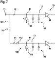
- FIG. 7 shows a schematic block diagram of a damping device 101 according to the invention according to a sixth embodiment of the invention, wherein the damping device 101 comprises a plurality of transmission paths 72, 73 with different attenuations.
- FIG. 7 an embodiment of the schematic diagram "parallel resistance" of the input stage of an evaluation unit 70 of an ultrasonic sensor (not marked) is shown as a multi-way input stage.
- FIG. 7 shows an alternative realization possibility of a piecewise signal attenuation.
- Small input signals pass through the capacitor 52 with the capacitance C 1 to the amplifier 60 included in the upper amplifier path 72, the small-signal impedance 83 of which has an impedance value R 1 . If the input signals clearly exceed the activation voltage of the protective circuit 90 of the upper amplifier path 72, in these cases the input impedance of the upper amplifier stage 72 is reduced to the impedance value of the capacitor 52 with the capacitance C 1, which is designed to be low impedance at most.
- Amplifier stages connected in parallel, such as the solution shown in the lower circuit 73, may pass such an input signal to the evaluation unit 70 after attenuation, using an additional attenuation such as that represented by the network 106.
- the network 106 includes a resistor 112 having a resistance R N1 and another resistor 113 having a resistance R N2 .
- the electro-acoustic converters are usually narrow-band and thus easily oscillatable structures, in particular, if they work together as usual with a transformer located in the transmit signal generator (transformer), the time response of the waveform with respect to the amplitude, the period and / or the frequency etc. characteristic of the state of the transducer and the objects in front of it.
- a transformer located in the transmit signal generator transmitter
- the time response of the waveform with respect to the amplitude, the period and / or the frequency etc. characteristic of the state of the transducer and the objects in front of it For example, an object located in front of the converter, such as, for example, an ice layer or a layer of mud on the vehicle and / or an object located closely in front of the vehicle, can be detected.
- a deviation of the sensor characteristics from the specified values may be determined to cause the repair and / or replacement of the converter at the next vehicle maintenance and / or sensor-dependent vehicle functions, such as Do not offer sensor-controlled training and / or parking due to the non-specification sensor parameters and / or to detect the damage to the vehicle or in time to detect the approaching of a damage causing objects, as they typically occur in an accident or near the vehicle.
- the resistors used in the realization can also be implemented as complex components, such as a combination of resistor and capacitor.
- complex resistance calculation The person skilled in the necessary rules of the complex resistance calculation are generally known and therefore not explained in detail.
Claims (5)
- Dispositif de balayage d'environnement destiné à déterminer la position et/ou le mouvement d'au moins un objet dans l'environnement d'un accessoire de mouvement au moyen d'au moins une impulsion sonore émise et réfléchie au niveau de l'objet, le dispositif de balayage d'environnement comprenant dans le trajet de réception un convertisseur électroacoustique (40) destiné à recevoir l'au moins une impulsion sonore réfléchie au niveau de l'objet et nommée impulsion d'écho et une unité d'interprétation (70) destinée à interpréter le signal du convertisseur électroacoustique (40), le dispositif de balayage d'environnement étant configuré pour atténuer le signal du convertisseur électroacoustique présent dans le trajet de réception au moyen d'un dispositif d'atténuation (101) au moins pendant le temps de réception de l'impulsion d'écho, et le dispositif de balayage d'environnement comprenant en outre une commande de temporisation (100) qui est configurée pour commander le dispositif d'atténuation (101) de telle sorte qu'une réduction de l'atténuation du signal du convertisseur électroacoustique (40) a lieu au moins pendant le temps de réception de l'impulsion d'écho, caractérisé en ce que le dispositif d'atténuation (101) possède plusieurs chemins de transmission (72, 73) ayant des atténuations différentes contenus dans le trajet de réception, lesquels forment respectivement un étage amplificateur d'entrée (72, 73) de l'unité d'interprétation (70), le dispositif de balayage d'environnement étant configuré pour transmettre le signal du convertisseur électroacoustique (40) pendant des périodes différentes au moyen des chemins de transmission (72, 73) du dispositif d'atténuation (101) commandé au moyen de la commande de temporisation et atténuer ainsi au moyen de l'atténuation qui est réduite au moins pendant le temps de réception de l'impulsion d'écho.
- Dispositif de balayage d'environnement selon la revendication 1, caractérisé en ce que le dispositif de balayage d'environnement est configuré pour déterminer le comportement dans le temps et/ou l'amplitude du signal du convertisseur électroacoustique (40) atténué au moyen du dispositif d'atténuation (101) et pour atténuer le signal du convertisseur électroacoustique (40) avant et/ou après la fin de l'émission d'une impulsion sonore générée au moyen du convertisseur électroacoustique (40).
- Procédé de détermination de la position et/ou du mouvement d'au moins un objet dans l'environnement d'un accessoire de mouvement au moyen d'au moins une impulsion sonore émise et réfléchie au niveau de l'objet, le procédé étant mis en oeuvre au moyen d'un dispositif de balayage d'environnement selon l'une des revendications précédentes, caractérisé en ce que le signal du convertisseur électroacoustique (40) présent dans le trajet de réception du dispositif de balayage d'environnement est atténué au moins pendant le temps de réception de l'impulsion sonore réfléchie au niveau de l'objet et nommée impulsion d'écho par technologie de circuit au moyen d'un dispositif d'atténuation (101) qui possède plusieurs chemins de transmission (72, 73) ayant des atténuations différentes contenus dans le trajet de réception, lesquels forment respectivement un étage amplificateur d'entrée (72, 73) d'une unité d'interprétation (70) configurée pour interpréter le signal du convertisseur électroacoustique (40), avec une atténuation qui est réduite au moins pendant le temps de réception, en ce que le signal du convertisseur électroacoustique (40) est transmis pendant des périodes différentes au moyen des chemins de transmission (72, 73) du dispositif d'atténuation (101).
- Procédé selon la revendication 3, caractérisé en ce que le comportement dans le temps et/ou l'amplitude du signal du convertisseur électroacoustique (40) atténué au moyen du dispositif d'atténuation (101) est déterminé(e), le signal du convertisseur électroacoustique (40) étant atténué avant et/ou après la fin de l'émission d'une impulsion sonore générée au moyen du convertisseur électroacoustique (40).
- Véhicule comprenant un dispositif de balayage d'environnement selon l'une des revendications 1 ou 2.
Applications Claiming Priority (2)
| Application Number | Priority Date | Filing Date | Title |
|---|---|---|---|
| DE102012200991A DE102012200991A1 (de) | 2012-01-24 | 2012-01-24 | Umfelderfassungsvorrichtung und dazugehöriges Verfahren zur Bestimmung der Position und/oder der Bewegung von einem Objekt |
| PCT/EP2012/074764 WO2013110389A1 (fr) | 2012-01-24 | 2012-12-07 | Dispositif de détection d'environnement et procédé correspondant pour la détermination de la position et/ou du déplacement d'un objet |
Publications (2)
| Publication Number | Publication Date |
|---|---|
| EP2807500A1 EP2807500A1 (fr) | 2014-12-03 |
| EP2807500B1 true EP2807500B1 (fr) | 2018-11-21 |
Family
ID=47469901
Family Applications (1)
| Application Number | Title | Priority Date | Filing Date |
|---|---|---|---|
| EP12808719.4A Active EP2807500B1 (fr) | 2012-01-24 | 2012-12-07 | Dispositif de détection d'environnement et procédé correspondant pour la détermination de la position et/ou du déplacement d'un objet |
Country Status (4)
| Country | Link |
|---|---|
| EP (1) | EP2807500B1 (fr) |
| CN (1) | CN104067140A (fr) |
| DE (1) | DE102012200991A1 (fr) |
| WO (1) | WO2013110389A1 (fr) |
Families Citing this family (6)
| Publication number | Priority date | Publication date | Assignee | Title |
|---|---|---|---|---|
| EP2852057B1 (fr) | 2013-09-20 | 2018-05-16 | Nxp B.V. | Circuit de traitement de signal audio et à ultrasons et circuit de traitement de signal ultrasonore et procédés associés |
| DE102014202869A1 (de) * | 2014-02-17 | 2015-08-20 | Robert Bosch Gmbh | Vorrichtung zur Umfeldsensorik mit verbesserter Dynamikanpassung |
| JP6388957B2 (ja) * | 2014-04-11 | 2018-09-12 | エスゼット ディージェイアイ テクノロジー カンパニー リミテッドSz Dji Technology Co.,Ltd | 近接感知システムおよび方法 |
| DE102015213989A1 (de) * | 2015-07-24 | 2017-01-26 | Robert Bosch Gmbh | Akustischer Sensor zum Aussenden und/oder Empfangen akustischer Signale |
| RU2627977C1 (ru) * | 2016-06-17 | 2017-08-14 | Акционерное Общество "Концерн "Океанприбор" | Способ обнаружения объекта и измерения его параметров |
| PL3724615T3 (pl) | 2017-12-15 | 2023-08-14 | Kistler Holding Ag | Czujnik wim z elektroakustycznymi przetwornikami |
Family Cites Families (16)
| Publication number | Priority date | Publication date | Assignee | Title |
|---|---|---|---|---|
| BE742465A (fr) * | 1968-12-11 | 1970-05-14 | ||
| US3624596A (en) * | 1970-03-10 | 1971-11-30 | Sona Labs Inc | Ultrasonic range-attenuable depth-measuring system |
| DE2155588C3 (de) * | 1970-11-10 | 1975-01-09 | Simrad A/S, Horten (Norwegen) | Echolotanlage mit einer automatischen Steuerung der Verstärkung der empfangenen Echosignale |
| JPS57500304A (fr) * | 1980-02-22 | 1982-02-18 | ||
| GB8418216D0 (en) * | 1984-07-17 | 1984-08-22 | Fisco Electronics Ltd | Distance sensing |
| GB8718717D0 (en) * | 1987-08-07 | 1987-09-16 | Sonin Inc | Measuring distances |
| DE3834158A1 (de) * | 1988-10-07 | 1990-04-12 | E T R Gmbh | Ultraschall-sensorsystem mit geregeltem verstaerker und sektoren definiert begrenzter daempfung |
| JP2543234B2 (ja) * | 1990-06-29 | 1996-10-16 | 松下電器産業株式会社 | 超音波式物体感知装置 |
| CN2081005U (zh) * | 1990-11-14 | 1991-07-17 | 李德恒 | 电扇阵风自动控制器 |
| DE19919227A1 (de) | 1999-04-28 | 2000-11-02 | Valeo Schalter & Sensoren Gmbh | Flexible Ansteuerung für KFZ-Nahbereichs-Pulsradar |
| JP2001221851A (ja) | 2000-02-07 | 2001-08-17 | Niles Parts Co Ltd | 超音波センサ装置 |
| CN2880611Y (zh) * | 2006-03-30 | 2007-03-21 | 刘振强 | 光学电子汽车安全自动控制装置 |
| CN101054086A (zh) * | 2006-04-12 | 2007-10-17 | 刘振强 | 微波(远近红外)汽车安全自控装置 |
| DE102008054789A1 (de) | 2008-12-17 | 2010-07-15 | Robert Bosch Gmbh | Verfahren und Vorrichtung zum Verstärken eines zur Fahrzeugumfelddetektion geeigneten Signals |
| DE102009000003A1 (de) | 2009-01-02 | 2010-07-08 | Robert Bosch Gmbh | Kameraanordnung zur Erfassung eines Scheibenzustandes einer Fahrzeugscheibe |
| DE102010020023A1 (de) * | 2010-05-10 | 2011-11-10 | Valeo Schalter Und Sensoren Gmbh | Verfahren und Vorrichtung zur Rauschoptimierung eines Echosignals zur Fahrzeugumfelderfassung sowie zugehörige Vorrichtung zur Fahrzeugumfelderfassung |
-
2012
- 2012-01-24 DE DE102012200991A patent/DE102012200991A1/de not_active Withdrawn
- 2012-12-07 WO PCT/EP2012/074764 patent/WO2013110389A1/fr active Application Filing
- 2012-12-07 CN CN201280067852.1A patent/CN104067140A/zh active Pending
- 2012-12-07 EP EP12808719.4A patent/EP2807500B1/fr active Active
Non-Patent Citations (1)
| Title |
|---|
| None * |
Also Published As
| Publication number | Publication date |
|---|---|
| EP2807500A1 (fr) | 2014-12-03 |
| CN104067140A (zh) | 2014-09-24 |
| WO2013110389A1 (fr) | 2013-08-01 |
| DE102012200991A1 (de) | 2013-07-25 |
Similar Documents
| Publication | Publication Date | Title |
|---|---|---|
| EP2807500B1 (fr) | Dispositif de détection d'environnement et procédé correspondant pour la détermination de la position et/ou du déplacement d'un objet | |
| EP1562050B1 (fr) | Procédé et dispositif pour adapter un seuil dans un disposif de détection | |
| EP3084470B1 (fr) | Procédé de détection d'échos de cible dans un signal de réception d'un capteur à ultrasons d'un véhicule automobile, dispositif de détection d'ultrasons et véhicule automobile | |
| DE10103936C2 (de) | Ultraschall-Sonarsystem und -verfahren mit Verwendung einer Sendefrequenz, die von einer Nachschwingungsfrequenz verschieden ist | |
| EP2984503B1 (fr) | Procédé de mesure par ultrason, notamment comme aide au stationnement pour véhicules, et systèmes de mesure par ultrason | |
| EP2144083B1 (fr) | Procédé de détermination dynamique du niveau de bruit | |
| EP2943806A1 (fr) | Dispositif et procédé pour des capteurs d'environnement | |
| DE102011102574B4 (de) | Verfahren zur Erzeugung einer Schwellwertkurve, Verfahren zur Entfernungsbestimmung und Vorrichtung zur Umfelderfassung in einem Fahrzeug | |
| DE102008044088A1 (de) | Verfahren zur dynamischen Ermittlung des Rauschlevels | |
| DE102016118712A1 (de) | Sonar basierend auf Ultraschallrauschen | |
| EP2512870B1 (fr) | Méthode et dispositif pour la détection d'objets prennant en compte les résultats de détection précedents | |
| DE19841154A1 (de) | Verfahren und Gerätesystem zur Messung der Laufzeit von Schallwellen | |
| DE102020000173A1 (de) | Erkennung von rauschinduzierter ultraschallsensorblindheit | |
| DE2157342C3 (de) | Doppler-Radarecho-Verarbeitungseinrichtung mit Bandsperrfilter und Torschaltung | |
| EP3132282A1 (fr) | Dispositif et procédé de détection sonore d'un environnement | |
| DE19721835C2 (de) | Schaltungsanordnung zum Betreiben eines Abstandssensors, insbesondere eines Ultraschallsensors | |
| DE102010020023A1 (de) | Verfahren und Vorrichtung zur Rauschoptimierung eines Echosignals zur Fahrzeugumfelderfassung sowie zugehörige Vorrichtung zur Fahrzeugumfelderfassung | |
| EP2805181B1 (fr) | Procédé pour déterminer la position et/ou le mouvement d'objets situés dans l'environnement d'un moyen d'aide au déplacement au moyen de signaux acoustiques et dispositif pour la mise en oeuvre dudit procédé | |
| DE102012213712A1 (de) | Verfahren zum Betrieb eines Ultraschallwandlers | |
| DE102013200433B4 (de) | Signalwandlereinheit, Vorrichtung und Verfahren zur Umfeldsensorik | |
| EP2800983B1 (fr) | Procédé et dispositif de détection de l'environnement pour déterminer la position d'au moins un objet situé dans l'environnement d'un moyen d'aide au déplacement au moyen d'au moins une impulsion acoustique | |
| DE102010064397B4 (de) | Verfahren und Vorrichtung zur verbesserten Abstandsbesimmung und/oder Freiraumerkennung im Nahbereich | |
| EP2904424B1 (fr) | Suppression de l'oscillation d'un convertisseur pour la détection environnementale | |
| DE102023121262A1 (de) | Bewegungskompensierte abstandserfassung mit gleichzeitigen up-chirp-down-chirp-wellenformen | |
| DE102018112597A1 (de) | Verfahren zum Betreiben einer Ultraschallsensorvorrichtung für ein Kraftfahrzeug, wobei zwei Ultraschallsignale zumindest teilweise gleichzeitig ausgesendet werden, Ultraschallsensorvorrichtung sowie Kraftfahrzeug |
Legal Events
| Date | Code | Title | Description |
|---|---|---|---|
| PUAI | Public reference made under article 153(3) epc to a published international application that has entered the european phase |
Free format text: ORIGINAL CODE: 0009012 |
|
| 17P | Request for examination filed |
Effective date: 20140825 |
|
| AK | Designated contracting states |
Kind code of ref document: A1 Designated state(s): AL AT BE BG CH CY CZ DE DK EE ES FI FR GB GR HR HU IE IS IT LI LT LU LV MC MK MT NL NO PL PT RO RS SE SI SK SM TR |
|
| DAX | Request for extension of the european patent (deleted) | ||
| GRAP | Despatch of communication of intention to grant a patent |
Free format text: ORIGINAL CODE: EPIDOSNIGR1 |
|
| INTG | Intention to grant announced |
Effective date: 20180801 |
|
| GRAS | Grant fee paid |
Free format text: ORIGINAL CODE: EPIDOSNIGR3 |
|
| GRAA | (expected) grant |
Free format text: ORIGINAL CODE: 0009210 |
|
| AK | Designated contracting states |
Kind code of ref document: B1 Designated state(s): AL AT BE BG CH CY CZ DE DK EE ES FI FR GB GR HR HU IE IS IT LI LT LU LV MC MK MT NL NO PL PT RO RS SE SI SK SM TR |
|
| REG | Reference to a national code |
Ref country code: CH Ref legal event code: EP |
|
| REG | Reference to a national code |
Ref country code: IE Ref legal event code: FG4D Free format text: LANGUAGE OF EP DOCUMENT: GERMAN |
|
| REG | Reference to a national code |
Ref country code: DE Ref legal event code: R096 Ref document number: 502012013881 Country of ref document: DE |
|
| REG | Reference to a national code |
Ref country code: AT Ref legal event code: REF Ref document number: 1068192 Country of ref document: AT Kind code of ref document: T Effective date: 20181215 |
|
| REG | Reference to a national code |
Ref country code: NL Ref legal event code: MP Effective date: 20181121 |
|
| PG25 | Lapsed in a contracting state [announced via postgrant information from national office to epo] |
Ref country code: ES Free format text: LAPSE BECAUSE OF FAILURE TO SUBMIT A TRANSLATION OF THE DESCRIPTION OR TO PAY THE FEE WITHIN THE PRESCRIBED TIME-LIMIT Effective date: 20181121 Ref country code: BG Free format text: LAPSE BECAUSE OF FAILURE TO SUBMIT A TRANSLATION OF THE DESCRIPTION OR TO PAY THE FEE WITHIN THE PRESCRIBED TIME-LIMIT Effective date: 20190221 Ref country code: LT Free format text: LAPSE BECAUSE OF FAILURE TO SUBMIT A TRANSLATION OF THE DESCRIPTION OR TO PAY THE FEE WITHIN THE PRESCRIBED TIME-LIMIT Effective date: 20181121 Ref country code: HR Free format text: LAPSE BECAUSE OF FAILURE TO SUBMIT A TRANSLATION OF THE DESCRIPTION OR TO PAY THE FEE WITHIN THE PRESCRIBED TIME-LIMIT Effective date: 20181121 Ref country code: LV Free format text: LAPSE BECAUSE OF FAILURE TO SUBMIT A TRANSLATION OF THE DESCRIPTION OR TO PAY THE FEE WITHIN THE PRESCRIBED TIME-LIMIT Effective date: 20181121 Ref country code: IS Free format text: LAPSE BECAUSE OF FAILURE TO SUBMIT A TRANSLATION OF THE DESCRIPTION OR TO PAY THE FEE WITHIN THE PRESCRIBED TIME-LIMIT Effective date: 20190321 Ref country code: NO Free format text: LAPSE BECAUSE OF FAILURE TO SUBMIT A TRANSLATION OF THE DESCRIPTION OR TO PAY THE FEE WITHIN THE PRESCRIBED TIME-LIMIT Effective date: 20190221 Ref country code: FI Free format text: LAPSE BECAUSE OF FAILURE TO SUBMIT A TRANSLATION OF THE DESCRIPTION OR TO PAY THE FEE WITHIN THE PRESCRIBED TIME-LIMIT Effective date: 20181121 |
|
| PG25 | Lapsed in a contracting state [announced via postgrant information from national office to epo] |
Ref country code: NL Free format text: LAPSE BECAUSE OF FAILURE TO SUBMIT A TRANSLATION OF THE DESCRIPTION OR TO PAY THE FEE WITHIN THE PRESCRIBED TIME-LIMIT Effective date: 20181121 Ref country code: AL Free format text: LAPSE BECAUSE OF FAILURE TO SUBMIT A TRANSLATION OF THE DESCRIPTION OR TO PAY THE FEE WITHIN THE PRESCRIBED TIME-LIMIT Effective date: 20181121 Ref country code: PT Free format text: LAPSE BECAUSE OF FAILURE TO SUBMIT A TRANSLATION OF THE DESCRIPTION OR TO PAY THE FEE WITHIN THE PRESCRIBED TIME-LIMIT Effective date: 20190321 Ref country code: SE Free format text: LAPSE BECAUSE OF FAILURE TO SUBMIT A TRANSLATION OF THE DESCRIPTION OR TO PAY THE FEE WITHIN THE PRESCRIBED TIME-LIMIT Effective date: 20181121 Ref country code: GR Free format text: LAPSE BECAUSE OF FAILURE TO SUBMIT A TRANSLATION OF THE DESCRIPTION OR TO PAY THE FEE WITHIN THE PRESCRIBED TIME-LIMIT Effective date: 20190222 Ref country code: RS Free format text: LAPSE BECAUSE OF FAILURE TO SUBMIT A TRANSLATION OF THE DESCRIPTION OR TO PAY THE FEE WITHIN THE PRESCRIBED TIME-LIMIT Effective date: 20181121 |
|
| PG25 | Lapsed in a contracting state [announced via postgrant information from national office to epo] |
Ref country code: CZ Free format text: LAPSE BECAUSE OF FAILURE TO SUBMIT A TRANSLATION OF THE DESCRIPTION OR TO PAY THE FEE WITHIN THE PRESCRIBED TIME-LIMIT Effective date: 20181121 Ref country code: DK Free format text: LAPSE BECAUSE OF FAILURE TO SUBMIT A TRANSLATION OF THE DESCRIPTION OR TO PAY THE FEE WITHIN THE PRESCRIBED TIME-LIMIT Effective date: 20181121 Ref country code: PL Free format text: LAPSE BECAUSE OF FAILURE TO SUBMIT A TRANSLATION OF THE DESCRIPTION OR TO PAY THE FEE WITHIN THE PRESCRIBED TIME-LIMIT Effective date: 20181121 |
|
| REG | Reference to a national code |
Ref country code: CH Ref legal event code: PL |
|
| REG | Reference to a national code |
Ref country code: DE Ref legal event code: R097 Ref document number: 502012013881 Country of ref document: DE |
|
| PG25 | Lapsed in a contracting state [announced via postgrant information from national office to epo] |
Ref country code: SK Free format text: LAPSE BECAUSE OF FAILURE TO SUBMIT A TRANSLATION OF THE DESCRIPTION OR TO PAY THE FEE WITHIN THE PRESCRIBED TIME-LIMIT Effective date: 20181121 Ref country code: RO Free format text: LAPSE BECAUSE OF FAILURE TO SUBMIT A TRANSLATION OF THE DESCRIPTION OR TO PAY THE FEE WITHIN THE PRESCRIBED TIME-LIMIT Effective date: 20181121 Ref country code: MC Free format text: LAPSE BECAUSE OF FAILURE TO SUBMIT A TRANSLATION OF THE DESCRIPTION OR TO PAY THE FEE WITHIN THE PRESCRIBED TIME-LIMIT Effective date: 20181121 Ref country code: LU Free format text: LAPSE BECAUSE OF NON-PAYMENT OF DUE FEES Effective date: 20181207 Ref country code: EE Free format text: LAPSE BECAUSE OF FAILURE TO SUBMIT A TRANSLATION OF THE DESCRIPTION OR TO PAY THE FEE WITHIN THE PRESCRIBED TIME-LIMIT Effective date: 20181121 Ref country code: SM Free format text: LAPSE BECAUSE OF FAILURE TO SUBMIT A TRANSLATION OF THE DESCRIPTION OR TO PAY THE FEE WITHIN THE PRESCRIBED TIME-LIMIT Effective date: 20181121 |
|
| REG | Reference to a national code |
Ref country code: IE Ref legal event code: MM4A |
|
| PLBE | No opposition filed within time limit |
Free format text: ORIGINAL CODE: 0009261 |
|
| STAA | Information on the status of an ep patent application or granted ep patent |
Free format text: STATUS: NO OPPOSITION FILED WITHIN TIME LIMIT |
|
| REG | Reference to a national code |
Ref country code: BE Ref legal event code: MM Effective date: 20181231 |
|
| 26N | No opposition filed |
Effective date: 20190822 |
|
| PG25 | Lapsed in a contracting state [announced via postgrant information from national office to epo] |
Ref country code: IE Free format text: LAPSE BECAUSE OF NON-PAYMENT OF DUE FEES Effective date: 20181207 Ref country code: SI Free format text: LAPSE BECAUSE OF FAILURE TO SUBMIT A TRANSLATION OF THE DESCRIPTION OR TO PAY THE FEE WITHIN THE PRESCRIBED TIME-LIMIT Effective date: 20181121 |
|
| PG25 | Lapsed in a contracting state [announced via postgrant information from national office to epo] |
Ref country code: BE Free format text: LAPSE BECAUSE OF NON-PAYMENT OF DUE FEES Effective date: 20181231 |
|
| PG25 | Lapsed in a contracting state [announced via postgrant information from national office to epo] |
Ref country code: LI Free format text: LAPSE BECAUSE OF NON-PAYMENT OF DUE FEES Effective date: 20181231 Ref country code: CH Free format text: LAPSE BECAUSE OF NON-PAYMENT OF DUE FEES Effective date: 20181231 |
|
| PG25 | Lapsed in a contracting state [announced via postgrant information from national office to epo] |
Ref country code: MT Free format text: LAPSE BECAUSE OF FAILURE TO SUBMIT A TRANSLATION OF THE DESCRIPTION OR TO PAY THE FEE WITHIN THE PRESCRIBED TIME-LIMIT Effective date: 20181121 |
|
| REG | Reference to a national code |
Ref country code: AT Ref legal event code: MM01 Ref document number: 1068192 Country of ref document: AT Kind code of ref document: T Effective date: 20181207 |
|
| PG25 | Lapsed in a contracting state [announced via postgrant information from national office to epo] |
Ref country code: TR Free format text: LAPSE BECAUSE OF FAILURE TO SUBMIT A TRANSLATION OF THE DESCRIPTION OR TO PAY THE FEE WITHIN THE PRESCRIBED TIME-LIMIT Effective date: 20181121 |
|
| PG25 | Lapsed in a contracting state [announced via postgrant information from national office to epo] |
Ref country code: AT Free format text: LAPSE BECAUSE OF NON-PAYMENT OF DUE FEES Effective date: 20181207 |
|
| PG25 | Lapsed in a contracting state [announced via postgrant information from national office to epo] |
Ref country code: HU Free format text: LAPSE BECAUSE OF FAILURE TO SUBMIT A TRANSLATION OF THE DESCRIPTION OR TO PAY THE FEE WITHIN THE PRESCRIBED TIME-LIMIT; INVALID AB INITIO Effective date: 20121207 Ref country code: CY Free format text: LAPSE BECAUSE OF FAILURE TO SUBMIT A TRANSLATION OF THE DESCRIPTION OR TO PAY THE FEE WITHIN THE PRESCRIBED TIME-LIMIT Effective date: 20181121 Ref country code: MK Free format text: LAPSE BECAUSE OF NON-PAYMENT OF DUE FEES Effective date: 20181121 |
|
| PGFP | Annual fee paid to national office [announced via postgrant information from national office to epo] |
Ref country code: GB Payment date: 20221222 Year of fee payment: 11 Ref country code: FR Payment date: 20221219 Year of fee payment: 11 |
|
| PGFP | Annual fee paid to national office [announced via postgrant information from national office to epo] |
Ref country code: IT Payment date: 20221230 Year of fee payment: 11 |
|
| P01 | Opt-out of the competence of the unified patent court (upc) registered |
Effective date: 20230509 |
|
| PGFP | Annual fee paid to national office [announced via postgrant information from national office to epo] |
Ref country code: DE Payment date: 20240227 Year of fee payment: 12 |