EP2807500B1 - Environment detection device and related method for determining the position and/or motion of an object - Google Patents
Environment detection device and related method for determining the position and/or motion of an object Download PDFInfo
- Publication number
- EP2807500B1 EP2807500B1 EP12808719.4A EP12808719A EP2807500B1 EP 2807500 B1 EP2807500 B1 EP 2807500B1 EP 12808719 A EP12808719 A EP 12808719A EP 2807500 B1 EP2807500 B1 EP 2807500B1
- Authority
- EP
- European Patent Office
- Prior art keywords
- signal
- damping
- electroacoustic transducer
- environment sensing
- sensing apparatus
- Prior art date
- Legal status (The legal status is an assumption and is not a legal conclusion. Google has not performed a legal analysis and makes no representation as to the accuracy of the status listed.)
- Active
Links
Images


Classifications
-
- G—PHYSICS
- G01—MEASURING; TESTING
- G01S—RADIO DIRECTION-FINDING; RADIO NAVIGATION; DETERMINING DISTANCE OR VELOCITY BY USE OF RADIO WAVES; LOCATING OR PRESENCE-DETECTING BY USE OF THE REFLECTION OR RERADIATION OF RADIO WAVES; ANALOGOUS ARRANGEMENTS USING OTHER WAVES
- G01S7/00—Details of systems according to groups G01S13/00, G01S15/00, G01S17/00
- G01S7/52—Details of systems according to groups G01S13/00, G01S15/00, G01S17/00 of systems according to group G01S15/00
- G01S7/523—Details of pulse systems
- G01S7/526—Receivers
- G01S7/529—Gain of receiver varied automatically during pulse-recurrence period
Description
Die vorliegende Erfindung betrifft eine Umfelderfassungsvorrichtung zur Bestimmung der Position und/oder der Bewegung von mindestens einem Objekt in der Umgebung eines Bewegungshilfsmittels mittels mindestens eines ausgesendeten und an dem Objekt reflektierten akustischen Pulses. Auch betrifft die Erfindung ein entsprechendes mittels der erfindungsgemäßen Umfelderfassungsvorrichtung durchführbares Verfahren und ein Fahrzeug mit einer erfindungsgemäßen Umfelderfassungsvorrichtung.The present invention relates to an environment detection device for determining the position and / or the movement of at least one object in the vicinity of a movement aid by means of at least one emitted and reflected on the object acoustic pulse. The invention also relates to a corresponding method which can be carried out by means of the surroundings detection device according to the invention and to a vehicle having an environment detection device according to the invention.
Zur akustischen Umfelderfassung von Fahrzeugen werden derzeit üblicherweise pulsweise messende Ultraschallsysteme verwendet, bei denen über einen Elektro-Akustik-Wandler kurze, mit Signalpulsen mit einer Pulsdauer von 0,3 ms modulierte, sinusförmige Trägersignale mit einer Frequenz von 48 KHz ausgesandt werden. Bei solchen Ultraschallsystemen wird der Abstand zu Objekten der Umgebung anhand der Laufzeit der Reflexe der ausgesandten Pulse an diesen Objekten und der Schallgeschwindigkeit bestimmt.For acoustic environment detection of vehicles usually pulse-measuring ultrasound systems are currently used, in which short pulse signals modulated with signal pulses with a pulse duration of 0.3 ms, sinusoidal carrier signals are emitted at a frequency of 48 kHz via an electro-acoustic transducer. In such ultrasound systems, the distance to objects of the environment is determined by the duration of the reflections of the emitted pulses on these objects and the speed of sound.
In der
Zur effektiven Energieausnutzung ist die Kapazität C des Koppelkondensators 50 zumeist so ausgelegt, dass seine Impedanz 1/(2π*f0*C) bei der Arbeitsfrequenz f0 gegenüber dem Wiederstandswert Ri des Wiederstands 80 vernachlässigbar ist, sodass der Eingangswiderstand der über den Anschluss 71 an dem Elektro-Akustik-Wandler 40 elektrisch gekoppelten Auswerteeinheit 70 für kleine Nutzspannungen vorwiegend durch den Widerstandswert Ri des Widerstands 80 bestimmt wird. Je nach Schaltungsauslegung des Verstärkers 60 wird der Widerstandswert Ri des an dem Eingang 61 des Verstärkers 60 elektrisch gekoppelten Wiederstands 80 auch von der Verstärkerschaltung bestimmt. Eine Schutzbeschaltung 90 verhindert die Zerstörung des Verstärkers 60 beim Senden und bei hohen Echoamplituden.For effective energy utilization, the capacitance C of the
In einigen Fällen enthält der Akustik-Elektro-Wandler 40 Schaltungsanteile (nicht dargestellt) zur Anpassung des Wandlers 40 an die Verstärkerimpedanz und/oder an den Sendeimpulsgenerator 20 und/oder an bestimmte klimatische Einflüsse, wie Feuchtigkeit und/oder Arbeitstemperatur.In some cases, the acoustic-to-
Objekte in besonders geringen Abständen von beispielsweise unter 10 cm können mit dieser bekannten Architektur nicht gemessen werden, da die Akustik-Elektro-Wandler 40 für solche Objekte eine Amplitude von 1 V und höher generiert. Um Objekte in besonders geringen Abständen messen zu können, reicht der Dynamikbereich heute üblicher Verstärker nicht aus.Objects with particularly small distances of, for example, less than 10 cm can not be measured with this known architecture, since the acousto-
Aus dem Dokument
In dem Dokument
In dem Dokument
Ferner beschreibt das Dokument
Weiterhin ist aus dem Dokument
Auch ist aus den Dokumenten
Erfindungsgemäß werden eine Umfelderfassungsvorrichtung zur Bestimmung der Position und/oder der Bewegung von mindestens einem Objekt in der Umgebung eines Bewegungshilfsmittels mittels mindestens eines ausgesendeten und an dem Objekt reflektierten akustischen Pulses und ein entsprechendes Verfahren gemäß den unabhängigen Ansprüchen 1 und 3 bereitgestellt. Die Unteransprüche zeigen bevorzugte Weiterbildungen der Erfindung.According to the invention, an environment detection device is provided for determining the position and / or the movement of at least one object in the vicinity of a movement aid by means of at least one emitted and reflected on the object acoustic pulse and a corresponding method according to the
Die erfindungsgemäße Umfelderfassungsvorrichtung zur Bestimmung der Position und/oder der Bewegung von mindestens einem Objekt in der Umgebung eines Bewegungshilfsmittels mittels mindestens eines ausgesendeten und an dem Objekt reflektierten akustischen Pulse umfasst einen Elektro-Akustik-Wandler zum Empfangen des mindestens einen an dem Objekt reflektierten und als Echopuls bezeichneten akustischen Pulses im Empfangspfad und eine Auswerteeinheit zum Auswerten des Signals des Akustik-Elektro-Wandlers. Dabei ist die Umfelderfassungsvorrichtung dazu ausgebildet, das Signal des im Empfangspfad vorhandenen Akustik-Elektrowandlers mittels einer in einer Eingangsstufe der Auswerteeinheit enthaltenen Bedämpfungsvorrichtung zumindest während der Empfangszeit des Echopulses zu bedämpfen. Weiterhin umfasst die Umfelderfassungsvorrichtung eine Zeitsteuerung, die dazu ausgebildet ist, die Bedämpfungsvorrichtung derart zu steuern, dass eine Verringerung der Bedämpfung des Signals des Elektro-Akustik-Wandlers zumindest während der Empfangszeit des Echopulses auftritt.The surroundings detection device according to the invention for determining the position and / or the movement of at least one object in the vicinity of a movement aid by means of at least one emitted and reflected on the object acoustic pulses comprises an electro-acoustic transducer for receiving the at least one reflected on the object and called echo pulse acoustic pulse in the receive path and an evaluation unit for evaluating the signal of the acoustic-electric converter. In this case, the surroundings detection device is designed to attenuate the signal of the acoustic electric converter present in the reception path by means of a damping device contained in an input stage of the evaluation unit, at least during the reception time of the echo pulse. Furthermore, the surroundings detection device comprises a time control, which is designed to control the damping device in such a way that a reduction in the attenuation of the signal of the electroacoustic transducer occurs at least during the reception time of the echo pulse.
Das erfindungsgemäße Verfahren zur Bestimmung der Position und/oder der Bewegung von mindestens einem Objekt in der Umgebung eines Bewegungshilfsmittels mittels mindestens eines ausgesendeten und an dem Objekt reflektierten akustischen Pulses wird mittels einer erfindungsgemäßen Umfelderfassungsvorrichtung durchgeführt. Dabei wird das Signal eines in dem Empfangspfad der Umfelderfassungsvorrichtung vorhandenen Akustik-Elektrowandlers zumindest während der Empfangszeit des an dem Objekt reflektierten und als Echopuls bezeichneten akustischen Pulses schaltungstechnisch mittels einer in einer Eingangsstufe einer Auswerteeinheit zum Auswerten des Signals des Akustik-Elektro-Wandlers enthaltenen Bedämpfungsvorrichtung zumindest während der Empfangszeit zeitabnehmend bedämpft.The method according to the invention for determining the position and / or the movement of at least one object in the vicinity of a movement aid by means of at least one emitted and reflected on the object acoustic pulse is performed by means of an environment detection device according to the invention. At least during the reception time of the acoustic pulse reflected in the object and referred to as the echo pulse, the signal of an acoustic electric transducer present in the receiving path of the surroundings detection device is switched by means of a damping device contained in an input stage of an evaluation unit for evaluating the signal of the acoustic / electrical converter attenuated during reception time-decreasing.
Die erfindungsgemäße Umfelderfassungsvorrichtung ist dazu ausgebildet, die Position und/oder die Bewegung von Objekten in der Umgebung von Bewegungshilfsmitteln wie Krankenfahrstühle, Segways, Fahrräder, Elektroautos, andere Fahrzeuge wie Autos, Busse und Lastkraftwagen mittels ausgesendeter pulsförmig modulierter akustischer Signale mit eine Pulsdauer von insbesondere 0,3 ms zu bestimmen. Mittels der erfindungsgemäßen Umfelderfassungsvorrichtung wird das Signal des Akustik-Elektro-Wandlers mit Beginn des Echozyklus, insbesondere spätestens unmittelbar nach dem Ende der Schallimpulsaussendung oder sogar etwas davor, schaltungstechnisch mit einer Bedämpfung bedämpft, die während des Echozyklus verringert wird.The environment detecting device according to the invention is adapted to the position and / or movement of objects in the vicinity of movement aids such as ambulances, Segways, bicycles, electric cars, other vehicles such as cars, buses and trucks by means of emitted pulse-shaped modulated acoustic signals with a pulse duration of 0 in particular To determine 3 ms. By means of the environment detecting device according to the invention the signal of the acoustic-electric converter with the beginning of the echo cycle, in particular at the latest immediately after the end of the sound pulse emission or even slightly before, attenuated circuitry with a damping, which is reduced during the echo cycle.
Mittels der Bedämpfung des Signals des Elektro-Akustik-Wandlers während der Empfangszeit der Echopulse wird erreicht, dass auch Objekte im Nahfeld anhand ihrer starken Echos detektiert werden können.By damping the signal of the electro-acoustic transducer during the reception time of the echo pulses is achieved that objects in the near field can be detected based on their strong echoes.
Erfindungsgemäß wurde erkannt, dass zu einem bestimmten Zeitpunkt eines Echozyklus stets nur ein Bruchteil des gesamten Dynamikbereichs des Empfangssignals auftreten kann. Durch die mit Zeit abnehmende Bedämpfung der Signale des Elektro-Akustik-Wandlers kann der Dynamikumfang einer nachfolgenden Signalauswertung insbesondere während und unmittelbar nach dem Aussenden der auszusendenden Pulse vergrößert werden. Dadurch können mittels der erfindungsgemäßen Umfelderfassungsvorrichtung sowohl Klein- als auch Großsignale aufwandsarm ausgewertet werden. Dadurch kann bei der akustischen Umfeldüberwachung mittels der erfindungsgemäßen Umfelderfassungsvorrichtung insbesondere eine störungsarme Unterscheidung der auftretenden Signalstärken sowie eine störungsarme Dopplerverschiebungsdetektion realisiert werden.According to the invention, it has been recognized that only a fraction of the total dynamic range of the received signal can always occur at a specific instant of an echo cycle. Due to the decreasing attenuation of the signals of the electro-acoustic transducer with time, the dynamic range of a subsequent signal evaluation can be increased in particular during and immediately after the emission of the pulses to be transmitted. As a result, both small and large signals can be evaluated with little effort by means of the environment detecting device according to the invention. As a result, in the case of the acoustic environment monitoring by means of the surroundings detection device according to the invention, in particular a low-noise distinction of the signal strengths that occur and a low-interference Doppler shift detection can be realized.
Bei einer besonders vorteilhaften Ausführungsform der Erfindung umfasst die Bedämpfungsvorrichtung mehrere mittels mindestens eines Schalters elektrisch koppelbare Bauelementen und die Zeitsteuerung ist dazu ausgebildet, die mehreren Bauelemente derart umzuschalten, dass die gewünschte Bedämpfung des Signals des Elektro- Akustik-Wandlers erfolgt, wobei die Umfelderfassungsvorrichtung vorzugsweise weiter dazu ausgebildet ist, die Schaltzeitpunkte und/oder die technischen Folgen des Umschaltens bei der Auswertung des Signals des Elektro-Akustik-Wandlers zu berücksichtigen.In a particularly advantageous embodiment of the invention, the damping device comprises a plurality of electrically coupled by at least one switch components and the timing is adapted to switch the plurality of components such that the desired attenuation of the signal of the electro-acoustic transducer is carried out, wherein the environment sensing device preferably further is designed to take into account the switching times and / or the technical consequences of the switching in the evaluation of the signal of the electro-acoustic transducer.
Mit anderen Worten, die Bedämpfung des Signals des Elektro-Akustik-Wandlers wird erfindungsgemäß in einfacher Weise durch Schaltvorgänge verändert. Insbesondere sind die Schaltzeitpunkte und optional die technischen Folgen des Umschaltens, wie zum Beispiel Einschwingvorgänge (Umschwingvorgänge) der nachfolgenden Auswerteeinheit bekannt und werden von ihr bei der Auswertung berücksichtigt.In other words, the attenuation of the signal of the electro-acoustic transducer is changed according to the invention in a simple manner by switching operations. In particular, the switching times and optionally the technical consequences of the switching, such as transient (Umschwingvorgänge) of the subsequent evaluation are known and are considered by her in the evaluation.
Bei einer besonders bevorzugten Ausführungsform der Erfindung umfasst die Bedämpfungsvorrichtung eine erste Bedämpfungsschaltung, die an einem ersten Anschluss mit dem Elektro-Akustik-Wandler und an einem zweiten Anschlusses mit einem Eingang eines nachfolgenden, in der Eingangsstufe einer nachfolgenden Auswerteeinheit enthaltenen Verstärkers elektrisch gekoppelt ist. Dabei umfasst die erste Bedämpfungsschaltung einen zwischen ihren Anschlüssen geschalteten Widerstand mit verstellbarem Widerstandswert und/oder mehrere zwischen ihren Anschlüssen mittels mindestens eines Schalters jeweils elektrisch koppelbare Widerstände mit unterschiedlichen Widerstandswerten. Erfindungsgemäß ist die Zeitsteuerung dazu ausgebildet, einen derartigen Widerstandswertverlauf des verstellbaren Widerstandes zu erzeugen und/oder die mehreren Widerstände derart umzuschalten, dass die Bedämpfung des Signals des Akustik-Elektro-Wandlers wie gewünscht erfolgt.In a particularly preferred embodiment of the invention, the damping device comprises a first damping circuit, which at a first terminal with the electro-acoustic transducer and at a second terminal with an input of a subsequent, in the input stage of a Following evaluation unit contained amplifier is electrically coupled. Here, the first damping circuit comprises a resistor connected between its terminals with adjustable resistance and / or more between their terminals by means of at least one switch each electrically coupled resistors with different resistance values. According to the invention, the time control is designed to generate such a resistance characteristic curve of the variable resistor and / or to switch the plurality of resistors in such a way that the attenuation of the signal of the acoustic-electric converter takes place as desired.
Bei einer weiteren bevorzugten Ausführungsform der Erfindung umfasst die Bedämpfungsvorrichtung eine zweite Bedämpfungsschaltung, die an einem ersten Anschluss mit dem Elektro-Akustik-Wandler, an einem zweiten Anschluss mit dem Eingang des nachfolgenden, in der Eingangsstufe der Auswerteeinheit enthaltenen Verstärkers und an mindestens einem dritten Anschluss mit einem Punkt mit festem Bezugspotential elektrisch gekoppelt ist. Dabei umfasst die zweite Bedämpfungsschaltung einen verstellbaren Widerstand und/oder mehrere mittels mindestens eines Schalters elektrisch koppelbare Widerstände, wobei der verstellbare Widerstand und/oder die mehreren Widerstände an einem ersten Ende mit dem ersten und dem zweiten Anschluss der zweiten Bedämpfungsschaltung jeweils elektrisch gekoppelt sind und an einem zweiten Ende mit einem dritten Anschluss der zweiten Bedämpfungsschaltung elektrisch gekoppelt oder mittels des mindestens eines Schalters jeweils koppelbar sind. Erfindungsgemäß ist die Zeitsteuerung dazu ausgebildet, einen derartigen Widerstandswertverlauf des verstellbaren Widerstandes zu erzeugen und/oder die mehreren Widerstände derart umzuschalten, dass die Bedämpfung des Signals des Elektro-Akustik-Wandlers wie gewünscht erfolgt.In a further preferred embodiment of the invention, the damping device comprises a second damping circuit, which at a first terminal with the electro-acoustic transducer, at a second terminal to the input of the subsequent amplifier included in the input stage of the evaluation and at least one third terminal is electrically coupled to a fixed reference point. In this case, the second damping circuit comprises an adjustable resistor and / or a plurality of electrically switchable by means of at least one switch resistors, wherein the variable resistor and / or the plurality of resistors are electrically coupled at a first end to the first and second terminals of the second damping circuit respectively a second end to a third terminal of the second damping circuit are electrically coupled or by means of the at least one switch in each case can be coupled. According to the invention, the time control is designed to generate such a resistance value profile of the variable resistor and / or to switch the plurality of resistors in such a way that the attenuation of the signal of the electroacoustic transducer takes place as desired.
Die Verwendung der erfindungsgemäßen Bedämpfungsschaltungen mit mehreren schaltbaren Widerständen mit unterschiedlichen Widerstandswerten, mittels denen eine nicht kontinuierliche Bedämpfung durch das Umschalten der mehreren Widerstandswerte realisiert wird, stellt eine vereinfachte, dadurch auch kostengünstige und durch die Berücksichtigung der Folgen des plötzlichen Umschaltens bei der Signalauswertung auch sehr zuverlässige Lösung dar.The use of the damping circuits according to the invention with a plurality of switchable resistors with different resistance values, by means of which a non-continuous damping is realized by switching the plurality of resistance values, provides a simplified, thereby cost-effective and also very reliable by taking into account the consequences of sudden switching in the signal evaluation Solution.
Weiterhin führt die Verwendung der erfindungsgemäßen Bedämpfungsschaltungen mit Widerständen, die jeweils einseitig an einem Punkt mit festem Bezugspotential verbunden sind, zu einer starken Vereinfachung der technischen Realisierung solcher Bedämpfungsvorrichtungen.Furthermore, the use of the damping circuits according to the invention with resistors, each one-sided at one point connected to a fixed reference potential, to a great simplification of the technical realization of such damping devices.
Erfindungsgemäß umfasst die erfindungsgemäße Bedämpfungsvorrichtung mehrere in dem Empfangspfad enthaltene Übertragungswege mit unterschiedlichen Signalbedämpfungen, die jeweils eine Eingangsstufe der Auswerteinheit bilden, wobei die genanten Eingangsstufen der Auswerteeinheit insbesondere jeweils eine Eingangsverstärkungsstufe umfassen. Dabei ist die erfindungsgemäße Umfelderfassungsvorrichtung dazu ausgebildet, das Signal des Elektro-Akustik-Wandlers während unterschiedlicher Zeiträume über unterschiedliche Übertragungswege mit unterschiedlichen Bedämpfungen zu übertragen und dadurch zu bedämpfen.
Mit anderen Worten erfolgt die Bedämpfung erfindungsgemäß dadurch, dass der Empfangspfad zumindest stückweise mehrere Übertragungswege mit unterschiedlicher Bedämpfung enthält.
Insbesondere in hochempfindlichen Verstärkerschaltungen kann das Vorhandensein von Schaltern in den Eingangsstufen, das bei der Erfindung dem Vorhandensein der Schalter in den Bedämpfungsschaltungen entspricht, nicht beseitigbare Störungen verursachen. Durch die Verwendung mehrerer Eingangsverstärkerstufen kann dieser Effekt unterdrückt werden.
Bei einer besonders bevorzugten Ausführungsform der Erfindung ist die Umfelderfassungsvorrichtung dazu ausgebildet, das Zeitverhalten und/oder die Amplitude des mittels der Bedämpfungsvorrichtung bedämpften Signals des Elektro-Akustik-Wandlers zu bestimmen und insbesondere das Signal des Akustik-Elektro-Wandlers auch vor dem Beginn des Empfanges des Echopulses, vorzugsweise vor und/oder nach dem Ende des Sendens eines mittels des Elektro-Akustik-Wandlers erzeugten akustischen Pulses zu bedämpfen.
Mit anderen Worten wird das Signal des Elektro-Akustik-Wandlers mittels der erfindungemäßen Umfelderfassungsvorrichtung insbesondere bezüglich seines Zeitverhaltens untersucht, wie zum Beispiel mittels der Bestimmung der Periodendauer anhand von Nulldurchgängen und/oder mittels der Bestimmung der zu den Periodendauern äquivalenten Signalfrequenz und/oder mittels der Bestimmung der Amplituden.According to the invention, the damping device according to the invention comprises a plurality of transmission paths with different signal attenuations contained in the reception path, each of which forms an input stage of the evaluation unit, the respective input stages of the evaluation unit each comprising in particular an input amplification stage. In this case, the environment detection device according to the invention is adapted to transmit the signal of the electro-acoustic transducer during different periods of time via different transmission paths with different attenuations and thereby dampen.
In other words, the attenuation according to the invention is carried out in that the receiving path contains at least in pieces several transmission paths with different attenuation.
Particularly in high-sensitivity amplifier circuits, the presence of switches in the input stages, which in the invention corresponds to the presence of the switches in the snubber circuits, can cause irreparable disturbances. By using multiple input amplifier stages this effect can be suppressed.
In a particularly preferred embodiment of the invention, the surroundings detection device is designed to determine the time behavior and / or the amplitude of the attenuated by the damping device signal of the electro-acoustic transducer and in particular the signal of the acoustic-to-electrical converter also before the beginning of the reception of the echo pulse, preferably before and / or after the end of the transmission of an acoustic pulse generated by means of the electro-acoustic transducer.
In other words, the signal of the electro-acoustic transducer is examined by means of the inventive Umfeldfassungsvorrichtung particularly with respect to its time behavior, such as by determining the period using zero crossings and / or by determining the equivalent to the period durations signal frequency and / or by means of Determination of the amplitudes.
Mittels der Bedämpfung des Signals des Akustik-Elektro-Wandlers während des Sendens und/oder unmittelbar nach dem Senden können die elektrische Signalverläufe insbesondere während des Sendens, d.h. bei Amplituden von über 100 V, zur Erkennung der Resonanzeigenschaften, Bandbreiten, Wirkungsgrad, Eigenüberwachung, usw. bezüglich ihres Amplitudenverlaufs beobachtet und ausgewertet werden.By means of the attenuation of the signal of the acousto-electric transducer during transmission and / or immediately after transmission, the electrical waveforms can be detected, in particular during transmission, i. at amplitudes of over 100 V, for the detection of the resonance characteristics, bandwidths, efficiency, self-monitoring, etc. are observed and evaluated in terms of their amplitude characteristic.
Erfindungsgemäß wird weiterhin ein Fahrzeug mit einer erfindungsgemäßen Umfelderfassungsvorrichtung bereitgestellt.According to the invention, a vehicle is provided with an environment detection device according to the invention.
Nachfolgend werden Ausführungsbeispiele der Erfindung unter Bezugnahme auf die begleitenden Zeichnungen im Detail beschrieben. In der Zeichnungen ist:
Figur 1- ein schematisches Blockschaltbild eines Ultraschallsensors nach dem Stand der Technik,
- Figur 2a
- ein schematisches Blockschaltbild der Eingangstufe einer Auswerteeinheit eines Ultraschallsensors mit einer erfindungsgemäßen Bedämpfungsvorrichtung nach einer ersten Ausführungsform der Erfindung,
- Figur 2b
- ein Zeitverlauf der in logarithmischen Skalierung dargestellten Widerstandswertänderung eines verstellbaren Widerstandes der Bedämpfungsvorrichtung nach der ersten Ausführungsform der Erfindung,
- Figur 3a
- ein schematisches Blockschaltbild der Eingangstufe einer Auswerteeinheit eines Ultraschallsensors mit einer erfindungsgemäßen Bedämpfungsvorrichtung nach einer zweiten Ausführungsform der Erfindung,
- Figur 3b
- ein Zeitverlauf der in logarithmischen Skalierung dargestellten Widerstandswertänderung eines verstellbaren Widerstandes der Bedämpfungsvorrichtung nach der zweiten Ausführungsform der Erfindung,
- Figur 4
- ein schematisches Blockschaltbild der Eingangstufe einer Auswerteeinheit eines Ultraschallsensors mit einer erfindungsgemäßen Bedämpfungsvorrichtung nach einer dritten Ausführungsform der Erfindung,
- Figuren 5a, 5b
- zwei schematische Blockschaltbilder der Eingangstufe einer Auswerteeinheit eines Ultraschallsensors mit einer erfindungsgemäßen Bedämpfungsvorrichtung nach einer vierten Ausführungsform der Erfindung,
- Figur 6
- ein schematisches Blockschaltbild einer erfindungsgemäßen Bedämpfungsvorrichtung nach einer fünften Ausführungsform der Erfindung, wobei die Bedämpfungsvorrichtung mehrere Übertragungswege mit unterschiedlichen Bedämpfungen umfasst, und
- Figur 7
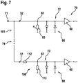
- ein schematisches Blockschaltbild einer erfindungsgemäßen Bedämpfungsvorrichtung nach einer sechsten Ausführungsform der Erfindung, wobei die Bedämpfungsvorrichtung mehrere Übertragungswege mit unterschiedlichen Bedämpfungen umfasst.
- FIG. 1
- a schematic block diagram of a ultrasonic sensor according to the prior art,
- FIG. 2a
- 2 shows a schematic block diagram of the input stage of an evaluation unit of an ultrasonic sensor with a damping device according to the invention according to a first embodiment of the invention,
- FIG. 2b
- a time course of the logarithmic scaling shown resistance value change of an adjustable resistor of the damping device according to the first embodiment of the invention,
- FIG. 3a
- FIG. 2 shows a schematic block diagram of the input stage of an evaluation unit of an ultrasonic sensor with a damping device according to the invention according to a second embodiment of the invention, FIG.
- FIG. 3b
- a time course of the resistance value change of an adjustable resistor shown in logarithmic scaling the damping device according to the second embodiment of the invention,
- FIG. 4
- FIG. 2 shows a schematic block diagram of the input stage of an evaluation unit of an ultrasonic sensor with a damping device according to the invention according to a third embodiment of the invention, FIG.
- FIGS. 5a, 5b
- two schematic block diagrams of the input stage of an evaluation unit of an ultrasonic sensor with a damping device according to the invention according to a fourth embodiment of the invention,
- FIG. 6
- a schematic block diagram of a damping device according to the invention according to a fifth embodiment of the invention, wherein the damping device comprises a plurality of transmission paths with different damping, and
- FIG. 7
- a schematic block diagram of a damping device according to the invention according to a sixth embodiment of the invention, wherein the damping device comprises a plurality of transmission paths with different attenuations.
In der
Die Bedämpfungsvorrichtung 101 nach der ersten Ausführungsform der Erfindung umfasst eine erste Bedämpfungsschaltung 102, die an einem ersten Anschluss (nicht dargestellt) mit einem Ausgang 71 des Elektro-Akustik-Wandlers (nicht dargestellt) insbesondere über den Koppelkondensator 50 und an einem zweiten Anschlusses (nicht dargestellt) mit einem Eingang 61 eines nachfolgenden, in der Auswerteeinheit 70 enthaltenen und insbesondere eine übliche Schutzschaltung 90 umfassenden Verstärkers 60 elektrisch gekoppelt ist, wobei die erste Bedämpfungsschaltung 102 einen zwischen ihren Anschlüssen (nicht dargestellt) geschalteten Widerstand 110 mit verstellbarem Widerstandswert umfasst. Die Eingangsstufe 72 umfasst ferner die Zeitsteuerung 100, die dazu ausgebildet ist, einen derartigen Widerstandswertverlauf des verstellbaren Widerstandes 110 zu erzeugen, dass die Bedämpfung des Signals des Elektro-Akustik-Wandlers zumindest während des Echozyklus zeitabnehmend erfolgt.The damping
Bei der in der
In der
Nachteilig bei der in
In der
Die Bedämpfungsvorrichtung 101 nach der zweiten Ausführungsform der Erfindung umfasst eine zweite Bedämpfungsschaltung 103, die an einem ersten Anschluss (nicht dargestellt) über den Koppelkondensator 50 und einen Widerstand 111 mit festem Widerstandswert R mit dem Ausgang 71 des Elektro-Akustik-Wandlers (nicht kennzeichnet), an einem zweiten Anschluss (nicht gekennzeichnet) mit einem Eingang 61 des nachfolgenden, in der Eingangsstufe 72 der Auswerteeinheit 70 enthaltenen Verstärkers 60 und an mindestens einem dritten Anschluss (nicht kennzeichnet) mit einem Punkt mit festem Bezugspotential 120 elektrisch gekoppelt ist, wobei die zweite Bedämpfungsschaltung 103 einen verstellbaren Widerstand 81 umfasst. Dabei ist der verstellbare Widerstand 81 an einem ersten Ende (nicht gekennzeichnet) mit dem ersten und dem zweiten Anschluss der zweiten Bedämpfungsschaltung 103 und an einem zweiten Ende mit dem dritten, an dem Punkt 120 mit einem festen Bezugspotential verbundenen Anschluss der zweiten Bedämpfungsschaltung 103 elektrisch gekoppelt. Dabei ist die Zeitsteuerung 100 dazu ausgebildet, einen derartigen Widerstandswertverlauf des verstellbaren Widerstandes 81 zu erzeugen, dass das Signals des Elektro- Akustik-Wandlers zeitabnehmend bedämpft wird.The damping
Um die hohen Signale während des Sendens beziehungsweise zu Beginn des Echozyklus, d.h. unmittelbar nach dem Senden den nachfolgenden Empfangsstufen (nicht dargestellt) der Auswerteinheit 70 nur stark bedämpft zur Verfügung zu stellen, muss der in der
In der
Dem Fachmann ist bekannt, dass der "Reihenwiderstand" 110 und der "Parallelwiderstand" 81 durch die Zeitsteuerung 100 gleichzeitig verändert werden können. Diese Lösung ist hier nicht gesondert dargestellt.It is known to the person skilled in the art that the "series resistance" 110 and the "parallel resistance" 81 can be changed simultaneously by the
Sowohl schaltungstechnisch als auch vom Zeitverhalten her sind die in den
In der
Die in der
Bei der in
Die
Die in der
Dabei umfassen die in der
Dabei umfassen die zweiten, in den
Die waagerechten Dreifachpunkte 89 deuten auf die Möglichkeit hin, dass in den Eingangsstufen 72 der Auswerteeinheiten 70 jeweils zusätzliche Bedämpfungsschaltungen enthalten sein können.The horizontal
Bei der zweiten, in der
Dem Fachmann ist bekannt, dass auf die Verwendung der Kondensatoren 51, 52 unter günstigen Randbedingungen auch verzichtet werden kann. Dies ist nicht gesondert dargestellt.It is known to the person skilled in the art that the use of the
Dem Fachmann ist auch bekannt, dass mittels eines Auswahlschalters, der eine von mehreren verfügbaren Verbindungen herstellt, bei der in
Bei der zweiten, in der
In der
Das an dem negativen Eingang 62 des Operationsverstärkers 60 befindliche Netzwerk 104, die mehrere schaltbare Widerstände 87, 88 umfasst, wurde bereits in der
In dem genannten Dokument wurde das Netzwerk 104 zur Erzeugung einer nichtkontinuierlichen, von der Laufzeit des Echosignals abhängigen Verstärkung des Signals des Elektro-Akustik-Wandlers (nicht dargestellt) verwendet.The
In the cited document, the
Vorteilhaft im Vergleich zu der in der
Das bisher dargestellte Konzept ist keine Regelung, sondern eine sehr einfache und daher kostengünstige Zeitsteuerung. Die Dämpfungsumschaltung findet ausschließlich von den Zeitpunkten des Aussendens der Schallimpulse statt. Insbesondere in hochempfindlichen Verstärkerschaltungen kann das Vorhandensein von Schaltern 130 in den Eingangsstufen 72 der Auswerteeinheiten 70 nicht beseitigbare Signalstörungen verursachen. Dies tritt insbesondere bei der Verwendung von Halbleiterbauelementen als Schalter auf. Durch die Verwendung mehreren Eingangsverstärkerstufen kann dieser Effekt unterdrückt werden, indem der Schalter erst nach einer ersten Verstärkung zum Einsatz kommt.The concept presented so far is not a regulation, but a very simple and therefore inexpensive time control. The attenuation switching takes place exclusively from the time of transmission of the sound pulses. Particularly in high-sensitivity amplifier circuits, the presence of
In der
Der obere, in der
Um extrem laute Eingangssignale mit gleicher Verstärkerarchitektur verarbeiten zu können, ist in der
Auf die Möglichkeit der Nutzung weiterer Verstärkerpfade sei durch die Verwendung von senkrechten Dreifachpunkten 74 hingewiesen.The possibility of using further amplifier paths is indicated by the use of vertical
Bei besonders robusten Ausführungen sind die einzelnen Verstärkerpfade 72, 73, wie durch die gestrichelte Linie 140 dargestellt, jeweils mittels eines eigenen Kondensators 50 an einem gemeinsamen Punkt 71 verbunden. Eine materialsparende Alternative zur Verbindung der Verstärkerpfade 72, 73 an einem gemeinsamen Kontaktpunkt 61 stellt die unmittelbar nach dem Kondensator 50 folgende senkrechte durchgezogene Verbindung 141 dar, die bei geeigneter Bauelementedimensionierung gewählt werden kann.In particularly robust embodiments, the
Auf die vielfältigen Möglichkeiten der Signalverarbeitung nach der ersten Verstärkerstufen 72, 73 wie beispielsweise eine weitere Verstärkung und/oder Filterung wird hier nicht eingegangen. Sie werden durch die waagerechte Dreifachpunkte 75 symbolisiert. Erwähnt sei insbesondere die einfache Lösung des mittels mindestens eines Schalters 130 durchgeführten Umschaltens zwischen den verschiedenen Verstärkungspfaden 72, 73, wie sie in der
In der
Auf die Nutzung der hier beschriebenen Großsignalbedämpfung zur Signalbewertung nach und insbesondere auch während des Aussendens von akustischen Messimpulsen sei hier besonders hingewiesen. Da es sich bei den Elektro-Akustik-Wandlern zumeist um schmalbandige und damit leicht schwingfähige Gebilde handelt, insbesondere, wenn sie wie üblich mit einem im Sendesignalgenerator befindlichen Übertrager (Transformator) zusammen arbeiten, ist das Zeitverhalten des Signalverlaufes bezüglich der Amplitude, der Periodendauer und/oder der Frequenz usw. charakteristisch für den Zustand des Wandlers und der vor ihm befindlichen Objekte. Beispielsweise kann ein vor dem Wandler befindliches Objekt wie zum Beispiel eine Eisschicht oder eine Matschschicht am Fahrzeug und/oder ein eng vor dem Fahrzeug befindliches Objekt erkannt werden.Reference should be made in particular to the use of the large-signal damping described here for signal evaluation according to and in particular also during the transmission of acoustic measurement pulses. Since the electro-acoustic converters are usually narrow-band and thus easily oscillatable structures, in particular, if they work together as usual with a transformer located in the transmit signal generator (transformer), the time response of the waveform with respect to the amplitude, the period and / or the frequency etc. characteristic of the state of the transducer and the objects in front of it. For example, an object located in front of the converter, such as, for example, an ice layer or a layer of mud on the vehicle and / or an object located closely in front of the vehicle, can be detected.
Insbesondere kann ein Abweichen der Sensoreigenschaften von den spezifizierten Werten bestimmt werden, um das Reparieren und/oder das Austauschen des Wandlers bei der nächsten Fahrzeugwartung zu veranlassen und/oder um sensorabhängige Fahrzeugfunktionen, wie zum Beispiel das sensorgeführte Aus- und/oder Einparken aufgrund der nicht spezifikationsgerechten Sensorparameter nicht anzubieten und/oder um die Schädigung des Fahrzeuges zu detektieren beziehungsweise um das Annähern von einen Schaden hervorrufenden Objekten, wie sie typischerweise bei einem Unfall oder auch im Fahrzeugnahfeld auftreten, rechtzeitig zu detektieren.In particular, a deviation of the sensor characteristics from the specified values may be determined to cause the repair and / or replacement of the converter at the next vehicle maintenance and / or sensor-dependent vehicle functions, such as Do not offer sensor-controlled training and / or parking due to the non-specification sensor parameters and / or to detect the damage to the vehicle or in time to detect the approaching of a damage causing objects, as they typically occur in an accident or near the vehicle.
Zur Erzielung spezieller Filtereffekte können die hier verwendeten Widerstände in der Realisierung auch als komplexe Bauelemente, wie beispielsweise als Kombination von Widerstand und Kondensator ausgeführt werden. Dem Fachmann sind die dazu notwendigen Regeln der komplexen Widerstandsberechnung im Allgemeinen bekannt und daher nicht im Detail erläutert.To achieve special filter effects, the resistors used in the realization can also be implemented as complex components, such as a combination of resistor and capacitor. The person skilled in the necessary rules of the complex resistance calculation are generally known and therefore not explained in detail.
Neben der voranstehenden schriftlichen Offenbarung wird hiermit zur weiteren Offenbarung der Erfindung ergänzend auf die Darstellung in den
Claims (5)
- Environment sensing apparatus for determining the position and/or the movement of at least one object in the surroundings of a mobility aid by means of at least one emitted acoustic pulse reflected from the object, wherein the environment sensing apparatus comprises, in the reception path, an electroacoustic transducer (40) for receiving the at least one acoustic pulse reflected from the object, and referred to as an echo pulse, and an evaluation unit (70) for evaluating the signal from the electroacoustic transducer (40), the environment sensing apparatus is configured to damp the signal from the electroacoustic transducer present in the reception path by means of a damping apparatus (101) at least during the reception time of the echo pulse, and the environment sensing apparatus further comprises a time controller (100) configured to control the damping apparatus (101) such that a decrease in the damping of the signal from the electroacoustic transducer (40) occurs at least during the reception time of the echo pulse, characterized in that the damping apparatus (101) has multiple transmission paths (72, 73), contained in the reception path, having different dampings that each form an input amplifier stage (72, 73) of the evaluation unit (70), wherein the environment sensing apparatus is configured to transmit the signal from the electroacoustic transducer (40) by means of different transmission paths (72, 73) of the damping apparatus (101) controlled by means of the time controller during different periods and, as a result, to damp said signal by means of the damping that decreases at least during the reception time of the echo pulse.
- Environment sensing apparatus according to Claim 1, characterized in that the environment sensing apparatus is configured to determine the time response and/or the amplitude of the signal from the electroacoustic transducer (40) damped by means of the damping apparatus (101) and to damp the signal from the electroacoustic transducer (40) before and/or after the end of transmission of an acoustic pulse produced by means of the electroacoustic transducer (40).
- Method for determining the position and/or the movement of at least one object in the surroundings of a mobility aid by means of at least one emitted acoustic pulse reflected from the object, wherein the method is performed by means of an environment sensing apparatus according to either of the preceding claims, characterized in that the signal from the electroacoustic transducer (40) present in the reception path of the environment sensing apparatus is damped by circuitry at least during the reception time of the acoustic pulse reflected from the object, and referred to as an echo pulse, by means of a damping apparatus (101) having multiple transmission paths (72, 73), comprised in the reception path, having different dampings, which each form an input amplifier stage (72, 73) of an evaluation unit (70) configured for evaluating the signal from the electroacoustic transducer (40), with a damping that is decreased at least during the reception time, by virtue of the signal from the electroacoustic transducer (40) being transmitted by means of different transmission paths (72, 73) of the damping apparatus (101) during different periods.
- Method according to Claim 3, characterized in that the time response and/or the amplitude of the signal from the electroacoustic transducer (40) that is damped by means of the damping apparatus (101) is determined, wherein the signal from the electroacoustic transducer (40) is damped before and/or after the end of transmission of an acoustic pulse produced by means of the electroacoustic transducer (40) .
- Vehicle having an environment sensing apparatus according to either of Claims 1 and 2.
Applications Claiming Priority (2)
| Application Number | Priority Date | Filing Date | Title |
|---|---|---|---|
| DE102012200991A DE102012200991A1 (en) | 2012-01-24 | 2012-01-24 | Environment detecting device and associated method for determining the position and / or movement of an object |
| PCT/EP2012/074764 WO2013110389A1 (en) | 2012-01-24 | 2012-12-07 | Environment detection device and related method for determining the position and/or motion of an object |
Publications (2)
| Publication Number | Publication Date |
|---|---|
| EP2807500A1 EP2807500A1 (en) | 2014-12-03 |
| EP2807500B1 true EP2807500B1 (en) | 2018-11-21 |
Family
ID=47469901
Family Applications (1)
| Application Number | Title | Priority Date | Filing Date |
|---|---|---|---|
| EP12808719.4A Active EP2807500B1 (en) | 2012-01-24 | 2012-12-07 | Environment detection device and related method for determining the position and/or motion of an object |
Country Status (4)
| Country | Link |
|---|---|
| EP (1) | EP2807500B1 (en) |
| CN (1) | CN104067140A (en) |
| DE (1) | DE102012200991A1 (en) |
| WO (1) | WO2013110389A1 (en) |
Families Citing this family (6)
| Publication number | Priority date | Publication date | Assignee | Title |
|---|---|---|---|---|
| EP2852057B1 (en) * | 2013-09-20 | 2018-05-16 | Nxp B.V. | An audio and ultrasound signal processing circuit and an ultrasound signal processing circuit, and associated methods |
| DE102014202869A1 (en) * | 2014-02-17 | 2015-08-20 | Robert Bosch Gmbh | Device for environment sensor technology with improved dynamic adaptation |
| JP6388957B2 (en) | 2014-04-11 | 2018-09-12 | エスゼット ディージェイアイ テクノロジー カンパニー リミテッドSz Dji Technology Co.,Ltd | Proximity sensing system and method |
| DE102015213989A1 (en) * | 2015-07-24 | 2017-01-26 | Robert Bosch Gmbh | Acoustic sensor for emitting and / or receiving acoustic signals |
| RU2627977C1 (en) * | 2016-06-17 | 2017-08-14 | Акционерное Общество "Концерн "Океанприбор" | Method of object detection and measurement of its parameters |
| EP3724615B1 (en) * | 2017-12-15 | 2023-06-07 | Kistler Holding AG | Wim sensor with electroacoustic transducers |
Family Cites Families (16)
| Publication number | Priority date | Publication date | Assignee | Title |
|---|---|---|---|---|
| BE742465A (en) * | 1968-12-11 | 1970-05-14 | ||
| US3624596A (en) * | 1970-03-10 | 1971-11-30 | Sona Labs Inc | Ultrasonic range-attenuable depth-measuring system |
| GB1363892A (en) * | 1970-11-10 | 1974-08-21 | Simrad As | Echo sounding apparatus with automatically regulated receiver gain |
| ZA811179B (en) * | 1980-02-22 | 1982-03-31 | Sonic Tape Plc | A distance sensing apparatus |
| GB8418216D0 (en) * | 1984-07-17 | 1984-08-22 | Fisco Electronics Ltd | Distance sensing |
| GB8718717D0 (en) * | 1987-08-07 | 1987-09-16 | Sonin Inc | Measuring distances |
| DE3834158A1 (en) * | 1988-10-07 | 1990-04-12 | E T R Gmbh | Ultrasound sensor system having a regulated amplifier and sectors whose attenuation is limited in a defined manner |
| JP2543234B2 (en) * | 1990-06-29 | 1996-10-16 | 松下電器産業株式会社 | Ultrasonic object sensing device |
| CN2081005U (en) * | 1990-11-14 | 1991-07-17 | 李德恒 | Autocontroller for gust wind of electric fan |
| DE19919227A1 (en) | 1999-04-28 | 2000-11-02 | Valeo Schalter & Sensoren Gmbh | Flexible control for automotive short-range pulse radar |
| JP2001221851A (en) | 2000-02-07 | 2001-08-17 | Niles Parts Co Ltd | Ultrasonic sensor apparatus |
| CN2880611Y (en) * | 2006-03-30 | 2007-03-21 | 刘振强 | Optical electronic for car safety auto-controller |
| CN101054086A (en) * | 2006-04-12 | 2007-10-17 | 刘振强 | Microwave (far and near infrared) automobile safety self-control device |
| DE102008054789A1 (en) | 2008-12-17 | 2010-07-15 | Robert Bosch Gmbh | Method and apparatus for amplifying a signal suitable for vehicle environment detection |
| DE102009000003A1 (en) | 2009-01-02 | 2010-07-08 | Robert Bosch Gmbh | Camera arrangement for detecting a wheel condition of a vehicle window |
| DE102010020023A1 (en) * | 2010-05-10 | 2011-11-10 | Valeo Schalter Und Sensoren Gmbh | Method and device for noise optimization of an echo signal for vehicle environment detection and associated device for vehicle environment detection |
-
2012
- 2012-01-24 DE DE102012200991A patent/DE102012200991A1/en not_active Withdrawn
- 2012-12-07 CN CN201280067852.1A patent/CN104067140A/en active Pending
- 2012-12-07 EP EP12808719.4A patent/EP2807500B1/en active Active
- 2012-12-07 WO PCT/EP2012/074764 patent/WO2013110389A1/en active Application Filing
Non-Patent Citations (1)
| Title |
|---|
| None * |
Also Published As
| Publication number | Publication date |
|---|---|
| WO2013110389A1 (en) | 2013-08-01 |
| EP2807500A1 (en) | 2014-12-03 |
| DE102012200991A1 (en) | 2013-07-25 |
| CN104067140A (en) | 2014-09-24 |
Similar Documents
| Publication | Publication Date | Title |
|---|---|---|
| EP2807500B1 (en) | Environment detection device and related method for determining the position and/or motion of an object | |
| EP1562050B1 (en) | Method and apparatus for adapting a threshold in a detection unit | |
| EP3084470B1 (en) | Method for detecting target echoes in a received signal of an ultrasonic sensor of a motor vehicle, ultrasonic sensor device, and motor vehicle | |
| DE10103936C2 (en) | Ultrasound sonar system and method using a transmit frequency that is different from a ringing frequency | |
| EP2984503B1 (en) | Method for measurement by means of ultrasound, in particular as a parking aid for vehicles, and ultrasound measuring systems | |
| EP2144083B1 (en) | Method for dynamic calculation of noise levels | |
| EP2943806A1 (en) | Device and method for environmental sensing | |
| DE102008044088A1 (en) | Method for the dynamic determination of the noise level | |
| DE102011102574A1 (en) | Method for generating threshold curve for evaluation of echo signal of ultrasonic transducer, involves emitting transmission signal over ultrasonic transducer and receiving and evaluating echo signal in response to transmission signal | |
| DE3513270A1 (en) | Device for distance measurement, in particular for motor vehicles | |
| EP2512870B1 (en) | Method and system for detecting objects taking into account previous detection results | |
| DE19841154A1 (en) | Measurement of propagation time of sound waves; involves measuring phase shift between transmitted and received signals at two different frequencies | |
| DE102020000173A1 (en) | DETECTING NOISE-INDUCED ULTRASONIC SENSOR BLINDNESS | |
| DE2157342C3 (en) | Doppler radar echo processing device with band-stop filter and gate circuit | |
| EP3132282A1 (en) | Apparatus and method for sound-based environment detection | |
| DE19721835C2 (en) | Circuit arrangement for operating a distance sensor, in particular an ultrasonic sensor | |
| DE102010020023A1 (en) | Method and device for noise optimization of an echo signal for vehicle environment detection and associated device for vehicle environment detection | |
| DE102012213712A1 (en) | Method for operating an ultrasonic transducer | |
| DE102013200433B4 (en) | Signal converter unit, apparatus and method for environment sensors | |
| EP2800983B1 (en) | Method and surroundings detection device for determining the position of at least one object in the surroundings of a mobility aid using at least one acoustic pulse | |
| DE102010064397B4 (en) | Method and device for improved distance determination and / or free space detection in the close range | |
| EP2805181B1 (en) | Method for determining the position and/or the movement of objects in the environment of a means of transportation by means of acoustic signals and device for carrying out said method | |
| EP2904424B1 (en) | Suppression of post-pulse oscillation of a converter for environmental detection | |
| DE102023121262A1 (en) | MOTION COMPENSATED DISTANCE DETECTION WITH SIMULTANEOUS UP-CHIRP-DOWN-CHIRP WAVEFORMS | |
| DE102018112597A1 (en) | Method for operating an ultrasonic sensor device for a motor vehicle, wherein two ultrasonic signals are transmitted at least partially simultaneously, ultrasonic sensor device and motor vehicle |
Legal Events
| Date | Code | Title | Description |
|---|---|---|---|
| PUAI | Public reference made under article 153(3) epc to a published international application that has entered the european phase |
Free format text: ORIGINAL CODE: 0009012 |
|
| 17P | Request for examination filed |
Effective date: 20140825 |
|
| AK | Designated contracting states |
Kind code of ref document: A1 Designated state(s): AL AT BE BG CH CY CZ DE DK EE ES FI FR GB GR HR HU IE IS IT LI LT LU LV MC MK MT NL NO PL PT RO RS SE SI SK SM TR |
|
| DAX | Request for extension of the european patent (deleted) | ||
| GRAP | Despatch of communication of intention to grant a patent |
Free format text: ORIGINAL CODE: EPIDOSNIGR1 |
|
| INTG | Intention to grant announced |
Effective date: 20180801 |
|
| GRAS | Grant fee paid |
Free format text: ORIGINAL CODE: EPIDOSNIGR3 |
|
| GRAA | (expected) grant |
Free format text: ORIGINAL CODE: 0009210 |
|
| AK | Designated contracting states |
Kind code of ref document: B1 Designated state(s): AL AT BE BG CH CY CZ DE DK EE ES FI FR GB GR HR HU IE IS IT LI LT LU LV MC MK MT NL NO PL PT RO RS SE SI SK SM TR |
|
| REG | Reference to a national code |
Ref country code: CH Ref legal event code: EP |
|
| REG | Reference to a national code |
Ref country code: IE Ref legal event code: FG4D Free format text: LANGUAGE OF EP DOCUMENT: GERMAN |
|
| REG | Reference to a national code |
Ref country code: DE Ref legal event code: R096 Ref document number: 502012013881 Country of ref document: DE |
|
| REG | Reference to a national code |
Ref country code: AT Ref legal event code: REF Ref document number: 1068192 Country of ref document: AT Kind code of ref document: T Effective date: 20181215 |
|
| REG | Reference to a national code |
Ref country code: NL Ref legal event code: MP Effective date: 20181121 |
|
| PG25 | Lapsed in a contracting state [announced via postgrant information from national office to epo] |
Ref country code: ES Free format text: LAPSE BECAUSE OF FAILURE TO SUBMIT A TRANSLATION OF THE DESCRIPTION OR TO PAY THE FEE WITHIN THE PRESCRIBED TIME-LIMIT Effective date: 20181121 Ref country code: BG Free format text: LAPSE BECAUSE OF FAILURE TO SUBMIT A TRANSLATION OF THE DESCRIPTION OR TO PAY THE FEE WITHIN THE PRESCRIBED TIME-LIMIT Effective date: 20190221 Ref country code: LT Free format text: LAPSE BECAUSE OF FAILURE TO SUBMIT A TRANSLATION OF THE DESCRIPTION OR TO PAY THE FEE WITHIN THE PRESCRIBED TIME-LIMIT Effective date: 20181121 Ref country code: HR Free format text: LAPSE BECAUSE OF FAILURE TO SUBMIT A TRANSLATION OF THE DESCRIPTION OR TO PAY THE FEE WITHIN THE PRESCRIBED TIME-LIMIT Effective date: 20181121 Ref country code: LV Free format text: LAPSE BECAUSE OF FAILURE TO SUBMIT A TRANSLATION OF THE DESCRIPTION OR TO PAY THE FEE WITHIN THE PRESCRIBED TIME-LIMIT Effective date: 20181121 Ref country code: IS Free format text: LAPSE BECAUSE OF FAILURE TO SUBMIT A TRANSLATION OF THE DESCRIPTION OR TO PAY THE FEE WITHIN THE PRESCRIBED TIME-LIMIT Effective date: 20190321 Ref country code: NO Free format text: LAPSE BECAUSE OF FAILURE TO SUBMIT A TRANSLATION OF THE DESCRIPTION OR TO PAY THE FEE WITHIN THE PRESCRIBED TIME-LIMIT Effective date: 20190221 Ref country code: FI Free format text: LAPSE BECAUSE OF FAILURE TO SUBMIT A TRANSLATION OF THE DESCRIPTION OR TO PAY THE FEE WITHIN THE PRESCRIBED TIME-LIMIT Effective date: 20181121 |
|
| PG25 | Lapsed in a contracting state [announced via postgrant information from national office to epo] |
Ref country code: NL Free format text: LAPSE BECAUSE OF FAILURE TO SUBMIT A TRANSLATION OF THE DESCRIPTION OR TO PAY THE FEE WITHIN THE PRESCRIBED TIME-LIMIT Effective date: 20181121 Ref country code: AL Free format text: LAPSE BECAUSE OF FAILURE TO SUBMIT A TRANSLATION OF THE DESCRIPTION OR TO PAY THE FEE WITHIN THE PRESCRIBED TIME-LIMIT Effective date: 20181121 Ref country code: PT Free format text: LAPSE BECAUSE OF FAILURE TO SUBMIT A TRANSLATION OF THE DESCRIPTION OR TO PAY THE FEE WITHIN THE PRESCRIBED TIME-LIMIT Effective date: 20190321 Ref country code: SE Free format text: LAPSE BECAUSE OF FAILURE TO SUBMIT A TRANSLATION OF THE DESCRIPTION OR TO PAY THE FEE WITHIN THE PRESCRIBED TIME-LIMIT Effective date: 20181121 Ref country code: GR Free format text: LAPSE BECAUSE OF FAILURE TO SUBMIT A TRANSLATION OF THE DESCRIPTION OR TO PAY THE FEE WITHIN THE PRESCRIBED TIME-LIMIT Effective date: 20190222 Ref country code: RS Free format text: LAPSE BECAUSE OF FAILURE TO SUBMIT A TRANSLATION OF THE DESCRIPTION OR TO PAY THE FEE WITHIN THE PRESCRIBED TIME-LIMIT Effective date: 20181121 |
|
| PG25 | Lapsed in a contracting state [announced via postgrant information from national office to epo] |
Ref country code: CZ Free format text: LAPSE BECAUSE OF FAILURE TO SUBMIT A TRANSLATION OF THE DESCRIPTION OR TO PAY THE FEE WITHIN THE PRESCRIBED TIME-LIMIT Effective date: 20181121 Ref country code: DK Free format text: LAPSE BECAUSE OF FAILURE TO SUBMIT A TRANSLATION OF THE DESCRIPTION OR TO PAY THE FEE WITHIN THE PRESCRIBED TIME-LIMIT Effective date: 20181121 Ref country code: PL Free format text: LAPSE BECAUSE OF FAILURE TO SUBMIT A TRANSLATION OF THE DESCRIPTION OR TO PAY THE FEE WITHIN THE PRESCRIBED TIME-LIMIT Effective date: 20181121 |
|
| REG | Reference to a national code |
Ref country code: CH Ref legal event code: PL |
|
| REG | Reference to a national code |
Ref country code: DE Ref legal event code: R097 Ref document number: 502012013881 Country of ref document: DE |
|
| PG25 | Lapsed in a contracting state [announced via postgrant information from national office to epo] |
Ref country code: SK Free format text: LAPSE BECAUSE OF FAILURE TO SUBMIT A TRANSLATION OF THE DESCRIPTION OR TO PAY THE FEE WITHIN THE PRESCRIBED TIME-LIMIT Effective date: 20181121 Ref country code: RO Free format text: LAPSE BECAUSE OF FAILURE TO SUBMIT A TRANSLATION OF THE DESCRIPTION OR TO PAY THE FEE WITHIN THE PRESCRIBED TIME-LIMIT Effective date: 20181121 Ref country code: MC Free format text: LAPSE BECAUSE OF FAILURE TO SUBMIT A TRANSLATION OF THE DESCRIPTION OR TO PAY THE FEE WITHIN THE PRESCRIBED TIME-LIMIT Effective date: 20181121 Ref country code: LU Free format text: LAPSE BECAUSE OF NON-PAYMENT OF DUE FEES Effective date: 20181207 Ref country code: EE Free format text: LAPSE BECAUSE OF FAILURE TO SUBMIT A TRANSLATION OF THE DESCRIPTION OR TO PAY THE FEE WITHIN THE PRESCRIBED TIME-LIMIT Effective date: 20181121 Ref country code: SM Free format text: LAPSE BECAUSE OF FAILURE TO SUBMIT A TRANSLATION OF THE DESCRIPTION OR TO PAY THE FEE WITHIN THE PRESCRIBED TIME-LIMIT Effective date: 20181121 |
|
| REG | Reference to a national code |
Ref country code: IE Ref legal event code: MM4A |
|
| PLBE | No opposition filed within time limit |
Free format text: ORIGINAL CODE: 0009261 |
|
| STAA | Information on the status of an ep patent application or granted ep patent |
Free format text: STATUS: NO OPPOSITION FILED WITHIN TIME LIMIT |
|
| REG | Reference to a national code |
Ref country code: BE Ref legal event code: MM Effective date: 20181231 |
|
| 26N | No opposition filed |
Effective date: 20190822 |
|
| PG25 | Lapsed in a contracting state [announced via postgrant information from national office to epo] |
Ref country code: IE Free format text: LAPSE BECAUSE OF NON-PAYMENT OF DUE FEES Effective date: 20181207 Ref country code: SI Free format text: LAPSE BECAUSE OF FAILURE TO SUBMIT A TRANSLATION OF THE DESCRIPTION OR TO PAY THE FEE WITHIN THE PRESCRIBED TIME-LIMIT Effective date: 20181121 |
|
| PG25 | Lapsed in a contracting state [announced via postgrant information from national office to epo] |
Ref country code: BE Free format text: LAPSE BECAUSE OF NON-PAYMENT OF DUE FEES Effective date: 20181231 |
|
| PG25 | Lapsed in a contracting state [announced via postgrant information from national office to epo] |
Ref country code: LI Free format text: LAPSE BECAUSE OF NON-PAYMENT OF DUE FEES Effective date: 20181231 Ref country code: CH Free format text: LAPSE BECAUSE OF NON-PAYMENT OF DUE FEES Effective date: 20181231 |
|
| PG25 | Lapsed in a contracting state [announced via postgrant information from national office to epo] |
Ref country code: MT Free format text: LAPSE BECAUSE OF FAILURE TO SUBMIT A TRANSLATION OF THE DESCRIPTION OR TO PAY THE FEE WITHIN THE PRESCRIBED TIME-LIMIT Effective date: 20181121 |
|
| REG | Reference to a national code |
Ref country code: AT Ref legal event code: MM01 Ref document number: 1068192 Country of ref document: AT Kind code of ref document: T Effective date: 20181207 |
|
| PG25 | Lapsed in a contracting state [announced via postgrant information from national office to epo] |
Ref country code: TR Free format text: LAPSE BECAUSE OF FAILURE TO SUBMIT A TRANSLATION OF THE DESCRIPTION OR TO PAY THE FEE WITHIN THE PRESCRIBED TIME-LIMIT Effective date: 20181121 |
|
| PG25 | Lapsed in a contracting state [announced via postgrant information from national office to epo] |
Ref country code: AT Free format text: LAPSE BECAUSE OF NON-PAYMENT OF DUE FEES Effective date: 20181207 |
|
| PG25 | Lapsed in a contracting state [announced via postgrant information from national office to epo] |
Ref country code: HU Free format text: LAPSE BECAUSE OF FAILURE TO SUBMIT A TRANSLATION OF THE DESCRIPTION OR TO PAY THE FEE WITHIN THE PRESCRIBED TIME-LIMIT; INVALID AB INITIO Effective date: 20121207 Ref country code: CY Free format text: LAPSE BECAUSE OF FAILURE TO SUBMIT A TRANSLATION OF THE DESCRIPTION OR TO PAY THE FEE WITHIN THE PRESCRIBED TIME-LIMIT Effective date: 20181121 Ref country code: MK Free format text: LAPSE BECAUSE OF NON-PAYMENT OF DUE FEES Effective date: 20181121 |
|
| PGFP | Annual fee paid to national office [announced via postgrant information from national office to epo] |
Ref country code: GB Payment date: 20221222 Year of fee payment: 11 Ref country code: FR Payment date: 20221219 Year of fee payment: 11 |
|
| PGFP | Annual fee paid to national office [announced via postgrant information from national office to epo] |
Ref country code: IT Payment date: 20221230 Year of fee payment: 11 Ref country code: DE Payment date: 20230223 Year of fee payment: 11 |
|
| P01 | Opt-out of the competence of the unified patent court (upc) registered |
Effective date: 20230509 |