EP2807401B1 - Seilstrumpfs und von einer kordel entfernte äussere schicht - Google Patents
Seilstrumpfs und von einer kordel entfernte äussere schicht Download PDFInfo
- Publication number
- EP2807401B1 EP2807401B1 EP12779034.3A EP12779034A EP2807401B1 EP 2807401 B1 EP2807401 B1 EP 2807401B1 EP 12779034 A EP12779034 A EP 12779034A EP 2807401 B1 EP2807401 B1 EP 2807401B1
- Authority
- EP
- European Patent Office
- Prior art keywords
- assembly
- layer
- tubular fabric
- filaments
- steel cords
- Prior art date
- Legal status (The legal status is an assumption and is not a legal conclusion. Google has not performed a legal analysis and makes no representation as to the accuracy of the status listed.)
- Not-in-force
Links
Images
Classifications
-
- F—MECHANICAL ENGINEERING; LIGHTING; HEATING; WEAPONS; BLASTING
- F16—ENGINEERING ELEMENTS AND UNITS; GENERAL MEASURES FOR PRODUCING AND MAINTAINING EFFECTIVE FUNCTIONING OF MACHINES OR INSTALLATIONS; THERMAL INSULATION IN GENERAL
- F16G—BELTS, CABLES, OR ROPES, PREDOMINANTLY USED FOR DRIVING PURPOSES; CHAINS; FITTINGS PREDOMINANTLY USED THEREFOR
- F16G11/00—Means for fastening cables or ropes to one another or to other objects; Caps or sleeves for fixing on cables or ropes
- F16G11/02—Means for fastening cables or ropes to one another or to other objects; Caps or sleeves for fixing on cables or ropes with parts deformable to grip the cable or cables; Fastening means which engage a sleeve or the like fixed on the cable
-
- D—TEXTILES; PAPER
- D07—ROPES; CABLES OTHER THAN ELECTRIC
- D07B—ROPES OR CABLES IN GENERAL
- D07B7/00—Details of, or auxiliary devices incorporated in, rope- or cable-making machines; Auxiliary apparatus associated with such machines
- D07B7/16—Auxiliary apparatus
- D07B7/169—Auxiliary apparatus for interconnecting two cable or rope ends, e.g. by splicing or sewing
-
- F—MECHANICAL ENGINEERING; LIGHTING; HEATING; WEAPONS; BLASTING
- F16—ENGINEERING ELEMENTS AND UNITS; GENERAL MEASURES FOR PRODUCING AND MAINTAINING EFFECTIVE FUNCTIONING OF MACHINES OR INSTALLATIONS; THERMAL INSULATION IN GENERAL
- F16G—BELTS, CABLES, OR ROPES, PREDOMINANTLY USED FOR DRIVING PURPOSES; CHAINS; FITTINGS PREDOMINANTLY USED THEREFOR
- F16G11/00—Means for fastening cables or ropes to one another or to other objects; Caps or sleeves for fixing on cables or ropes
- F16G11/08—Fastenings for securing ends of driving-cables to one another, the fastenings having approximately the same diameter as the cables
Definitions
- the invention relates to a tubular fabric for connecting two steel cords, and an assembly of two steel cords and a tubular fabric for connecting said steel cords at two connecting ends.
- the invention further relates to a method of connecting two steel cords at two connecting ends by means of a tubular fabric.
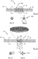
- FIG. 1a shows a longitudinal view
- Figure 1b a cross-section according to plane I-I
- Figure 1c a cross-section according to plane II-II.
- Chinese finger 100 is composed of metal threads or wires 12 helically interwoven or braided to form a cylindrical braiding. Between adjacent successive threads 12 in the axial direction and in the peripheral direction, are spaces 13.
- the resulting network of lozenges is very flexible and facilitates radial expansion and contraction of the tubular fabric when it is positioned on the ends of two steel cords and contraction and gripping of those ends when the joined cords are subjected to forces tending to pull the cords from one another.
- the general purpose is to use such a tubular fabric or Chinese finger to connect two steel cords each time there is a fracture during twisting.
- GB 1462 735 disclosed a tubular fabric which was similar to that shown in Figure 1 a except that the braiding formed by the metal threads or wires were embedded in a rubber cylindrical body. This cylindrical body naturally filled the spaces between the metal threads or wires. However, because of the elastomeric cylindrical body, it might be insufficient to subject the tubular fabric to a slight axial compression to make it expand radially and allow it to be positioned easily on the ends of two steel cords which are to be connected.
- US 2596 513 also disclosed a coupling or joint of a Chinese finger, the two connecting ends of the belt may be cut down to form a shoulder and cylindrical end portions which permit the coupling to surround these end portions and still not enlarge the resulting diameter substantially beyond that of the belt.
- the belt of a rope or the like when the diameter is so small that the paring down of the belt ends to accommodate the coupling is not desirable and a slight increase in diameter will not be detrimental.
- a method to avoid a substantial increase in diameter on the other hand, for a belt of the rope or the like, e.g. steel cord, as the diameter of the filaments is too small to be cut down, it may have undesirable results in operation, e.g. at a high risk of fracture.
- the primary object of the invention is to mitigate drawbacks of the prior arts.
- the further object of the invention is to decrease the diameter over the length of the tubular fabric.
- the another object of the invention is to increase tensile strength at level of fracture.
- an assembly of two steel cords and a tubular fabric for connecting the steel cords at two connecting ends are multi-layer steel cords having a core and at least one layer and possibly a wrapping filament, e.g. a core of one filament or a plurality of filaments and one layer or two or more layers with a plurality of filaments of each layer twisted around the core, further a wrapping filament may be wrapped around the outer layer of such steel cords.
- a wrapping filament e.g. a core of one filament or a plurality of filaments and one layer or two or more layers with a plurality of filaments of each layer twisted around the core
- At least one layer is absent at the two connecting ends of said steel cords over a total length L 2 .
- the tubular fabric is positioned so that it fits within the total length L 2 thereby avoiding an increase in diameter of the steel cords with twice the wall thickness of the tubular fabric over this length L 2 .
- the tubular fabric of the assembly according to the invention has a particular length L 1 ranging from 0.5 cm to 20 cm, e.g. 1 cm to 3 cm or 5 cm to 10 cm. If the length L 1 is shorter than 0.5 cm, it would not sufficient to subject the tubular fabric to provide a strong connection of the two ends of the cords, which would easily cause tensile strength decreasing at level of fracture. If the length L 1 is longer than 20 cm, it would be a waste of material and a longer tubular fabric can not facilitate their positioning over the two ends of the cords to be connected.
- the tubular fabric with a particular length L 1 is positioned so that it fits within the total length L 2 , L 1 and L 2 preferably satisfy the expression L 1 ⁇ L 2 .
- the tubular fabric has a wall thickness ⁇ while at least one layer of the multi-layer steel cord has filaments with a maximum diameter of d l , which means that the absence of said at least one layer results in a thickness decrease of 2xd l over a length L 2 while further positioning of said tubular fabric is resulting in a thickness increase of 2x ⁇ over a length L 1 . That's to say, the global effect on the joint part of such an assembly according to the invention is 2x ⁇ - 2xd l over a length L 1 . 2x ⁇ - 2xd l can either be positive or negtive in order to avoid an increase in diameter over the length L 2 .
- the multi-layer steel cord comprises a core and an inner layer twisted around the core and further an outer layer twisted around the inner layer, e.g.1+6+12 or 3+9+15 multi-layer steel cord construction with a core filament and an inner layer of six filaments twisted around the core filament and twelve filaments as an outer layer further twisted around the inner layer. Possibly, there is a wrapping filament wrapped around the outer layer, this is then referred to as 1+6+12 +1 or 3+9+15 +1.
- the outer layer or both of the outer layer and the wrapping filament is/are removed at the two connecting ends, e.g. for a multi-layer steel cord construction with a wrapping filament 3+9+15 +1, the outer layer of fifteen filaments or both of the fifteen filaments and the wrapping filament is/are removed at the two connecting ends resulting in a reduction of the diameter at the two connecting ends.
- the two connecting ends will have a decreased diameter because of the absence of the outer layer or both of the outer layer and the wrapping filament at the two connecting ends of the steel cords. This would further avoid an increase in diameter when the tubular fabric is put over both steel cord ends.
- the two connecting ends will have a decreased diameter because of the absence of the inner layer or both of the inner layer and the core at the two connecting ends of the steel cords, e.g. for a multi-layer steel cord construction with a wrapping filament 1+6+12 +1, the inner layer of six filaments or both of the core filament and the inner layer of six filaments is/are removed at the two connecting ends. This would further avoid an increase in diameter when the tubular fabric is put over both steel cord ends.
- each connecting end may be heated by electrical resistance and overtwisted together in order to be further connected by the tubular fabric to form an assembly according to the invention.
- the heating may be effected by various simple means such as a heating press or gripper with jaws gripping and encompassing the two connecting ends.
- the assembly of the invention preferably, the two ends of the tubular fabric are soldered to the exterior filaments of the steel cords in order to obtain a sufficiently high breaking strength of the joint part and allow proper tensioning of the assembly.
- a solder has proven to provide a stronger bonding than an adhesive resin.
- a solder is to be preferred above a weld, since welding may make the assembly too brittle.
- a method of connecting two steel cords at two connecting ends by means of a tubular fabric comprises the steps:
- a method of connecting two steel cords at two connecting ends by means of a tubular fabric comprises the steps:
- Fractures of a steel cord may happen during the twisting process.
- the joint part which is the part where two steel cords are joined together, it is desirable to have a strong connection as well as an equal diameter or a minimized change in diameter.
- the known assembly 10 shown in Figure 1 a is composed of two steel cords 14 connected by a known connector tubular fabric 100.
- the diameter (a radial thickness) of the assembly over the length of the tubular fabric is equal to the sum of diameter of the steel cord itself and the radial thickness of the tubular fabric. So there is a substantial increase in diameter.
- the connector tubular fabric or the Chinese finger there may be different embodiments of the connector tubular fabric or the Chinese finger, but two specific examples are: One with sixteen filaments with a diameter of 0.11 cm illustrated as the tubular fabric 100 and one with thirty-two filaments with a diameter of 0.09 cm illustrated as the tubular fabric 200.
- the tensile strength of the filaments of the two Chinese fingers is preferred to be ultra tensile strength, which means at least 3800 MPa.
- a first preferred embodiment 20 according to the invention and shown in Figure 2a is similar to that shown in Figure 1 a except that at the two connecting ends 16 of the steel cords 14 the six filaments of the outer layer are absent over a total length L 2 ' as can be seen from a comparison of cross-sections Fig. 2b and Fig. 2c .
- This means that the tubular fabric 200 with a particular length L 1 ' when positioned and fitting within the total length L 2 ' of one core filament does not increase the diameter, at least not over the length L 2 ' .
- the two ends of tubular fabric are soldered to the exterior filaments of the steel cords in order to increase tensile strength at level of fracture. If the two ends of tubular fabric are not soldered to the exterior filaments of the steel cords, the connection of the two ends of the steel cords is bad, which will cause too big a loss of tensile strength at level of fracture.
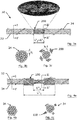
- a second preferred embodiment 30 shown in Figure 3a illustrates the assembly according to the invention.
- the fifteen filaments of the outer layer are absent over a total length L2".
- the tubular fabric 200 with a particular length L1" is positioned and just matches with the total length L2". The result is that the diameter of the assembly over the length L2" decreases significantly compared with the known assembly shown in Figure 1 .
- Removal of the outer layer filaments at the two connecting ends of the two steel cords is also done manually and with appropriate cutting means, e.g. by means of a pair of pliers. Then the remaining filaments at the two connecting ends of the steel cord - the three core filaments and the inner layer nine filaments - are heated and overtwisted in order to obtain a thinner radial diameter of the ends further to contribute to the diameter decreasing of the assembly over the length L2 " . This heating is also done to avoid contact stresses between the cord ends and the Chinese finger thereby leading to an improved breaking load of the connection.
- tubular fabric After that, the two ends of tubular fabric are soldered to the exterior filaments of the steel cords in order to increase tensile strength at level of fracture.
- a wrapping filament 24 is wrapping the steel cord 22 but no wrapping on top of the tubular fabric is done in order to avoid the diameter increasing of the joint part of the assembly.
- wrapping may be done over the assembly and the tubular fabric.
- the drawback is that this increases the diameter, but the advantage is that this continuous wrapping without interruptions strengthens the assembly.
- a third embodiment shown in Figure 4 according to the invention is also about an assembly of a tubular fabric 100 for connecting two ends of a steel cord 32 further with a wrapping filament 34, e.g. 1+6+12+1 steel cord construction.
- the core filament and the six filaments of the inner layer are absent over a total length L 2 '" .
- Removal of the core filament and the inner layer filaments at the two connecting ends of the two steel cords is also done manually and with appropriate cutting means, e.g. first untwisting the outer layer, then removing the core filament and the inner layer filaments by means of a pair of pliers, and thereafter twisting again the outer layer filaments.
- the two ends of the steel cord 32 are then connected by means of a tubular fabric resulting in a connected assembly after the two ends of tubular fabric are soldered to the exterior filaments of the steel cords in order to increase tensile strength at level of fracture.
- the invention is not limited to the assemblies of the embodiments above, but that it may also be applied to assemblies comprising a tubular fabric for connecting two ends of a steel cord or steel cords with a non-increasing diameter over the length of the tubular fabric.
Landscapes
- Engineering & Computer Science (AREA)
- General Engineering & Computer Science (AREA)
- Mechanical Engineering (AREA)
- Ropes Or Cables (AREA)
Claims (16)
- Baugruppe (20) aus zwei Stahlseilen (14) und einem schlauchförmigen Gewebe (200) zum Verbinden der Stahlseile (14) an zwei Verbindungsenden,
wobei die Stahlseile (14) mehrschichtige Stahlseile mit einem Kern und wenigstens einer Schicht und möglichst einem Umhüllungsfilament (24, 34) sind, dadurch gekennzeichnet, dass wenigstens eine Schicht an den beiden Verbindungsenden der Stahlseile (14) über eine Gesamtlänge L2 nicht vorhanden ist, wobei das schlauchförmige Gewebe (200) so angeordnet ist, dass es wenigstens einen Teil der Gesamtlänge L2 bedeckt, um so eine Zunahme des Durchmessers der Stahlseile (14) um zweimal die Wanddicke des schlauchförmigen Gewebes (200) über die Länge L2 zu vermeiden. - Baugruppe (20) gemäß Anspruch 1, wobei das schlauchförmige Gewebe (200) eine besondere Länge L1 in dem Bereich von 0,5 cm bis 20 cm aufweist.
- Baugruppe (20) gemäß Anspruch 2, wobei L1 kleiner als oder gleich L2 ist.
- Baugruppe (20) gemäß Anspruch 3, wobei das schlauchförmige Gewebe (200) eine Wanddicke δ aufweist und wobei die wenigstens eine Schicht Filamente mit einem Maximaldurchmesser von dl aufweist, wobei das Fehlen der wenigstens einen Schicht zu einer Dickenabnahme von 2xdl über eine Länge L2 führt, wobei das Positionieren des schlauchförmigen Gewebes (200) zu einer Dickenzunahme von 2xδ über eine Länge L1 führt, wobei die Gesamtwirkung 2xδ - 2xdl über eine Länge L1 beträgt.
- Baugruppe (20) gemäß Anspruch 4, wobei 2xδ - 2xdl positiv ist.
- Baugruppe (20) gemäß Anspruch 4, wobei 2xδ - 2xdl negativ ist.
- Baugruppe (20) gemäß Anspruch 1, wobei das mehrschichtige Stahlseil (14) einen Kern und eine innere Schicht, die um den Kern gewunden ist, und ferner eine äußere Schicht, die um die innere Schicht gewunden ist, und dann das Umhüllungsfilament (24, 34) umfasst.
- Baugruppe (20) gemäß Anspruch 7, wobei das mehrschichtige Stahlseil (14) einen Kern aus drei Filamenten und eine innere Schicht aus neun Filamenten, die um den Kern gewunden ist, und ferner eine äußere Schicht aus fünfzehn Filamenten, die um die innere Schicht gewunden ist, und dann ein weiteres Umhüllungsfilament umfasst.
- Baugruppe (20) gemäß Anspruch 7, wobei das mehrschichtige Stahlseil (14) einen Kern aus nur einem Filament und eine innere Schicht aus sechs Filamenten, die um den Kern gewunden ist, und ferner eine äußere Schicht aus zwölf Filamenten, die um die innere Schicht gewunden ist, und dann ein weiteres Umhüllungsfilament (24, 34) umfasst.
- Baugruppe (20) gemäß Anspruch 7, wobei die äußere Schicht oder sowohl die äußere Schicht als auch das Umhüllungsfilament an den beiden Verbindungsenden entfernt ist/sind.
- Baugruppe (20) gemäß Anspruch 7, wobei die innere Schicht oder sowohl der Kern als auch die innere Schicht an den beiden Verbindungsenden entfernt ist/sind.
- Baugruppe (20) gemäß Anspruch 10 oder 11, wobei die verbleibenden Filamente jedes Verbindungsendes durch elektrischen Widerstand erhitzt und zusammengedrillt werden können.
- Baugruppe (20) gemäß einem der Ansprüche 1 bis 12, wobei die beiden Enden des schlauchförmigen Gewebes an die äußeren Filamente der Stahlseile gelötet sind.
- Verfahren zum Verbinden von zwei mehrschichtigen Stahlseilen (14) an zwei Verbindungsenden mithilfe eines schlauchförmigen Gewebes (200), wobei das Verfahren die Schritte umfasst:- Entfernen wenigstens einer Schicht an den beiden Verbindungsenden der beiden Stahlseile;- Erhitzen der verbleibenden Filamente und Zusammendrillen der verbleibenden Filamente;- Verbinden der beiden Enden mithilfe eines schlauchförmigen Gewebes.
- Verfahren gemäß Anspruch 14, wobei das Erhitzen der verbleibenden Filamente mithilfe von elektrischer Widerstandsheizung durchgeführt wird.
- Verfahren gemäß Anspruch 14, wobei das Verfahren zusätzlich den Schritt umfasst:- Umhüllen der verbundenen Baugruppe mithilfe eines Umhüllungsfilaments (24, 34), wobei Umhüllen auf dem schlauchförmigen Gewebe vermieden wird.
Priority Applications (1)
| Application Number | Priority Date | Filing Date | Title |
|---|---|---|---|
| EP12779034.3A EP2807401B1 (de) | 2012-01-26 | 2012-10-24 | Seilstrumpfs und von einer kordel entfernte äussere schicht |
Applications Claiming Priority (3)
| Application Number | Priority Date | Filing Date | Title |
|---|---|---|---|
| EP12152655 | 2012-01-26 | ||
| EP12779034.3A EP2807401B1 (de) | 2012-01-26 | 2012-10-24 | Seilstrumpfs und von einer kordel entfernte äussere schicht |
| PCT/EP2012/071027 WO2013110362A1 (en) | 2012-01-26 | 2012-10-24 | Chinese finger and outer layer removed from cord |
Publications (2)
| Publication Number | Publication Date |
|---|---|
| EP2807401A1 EP2807401A1 (de) | 2014-12-03 |
| EP2807401B1 true EP2807401B1 (de) | 2017-03-01 |
Family
ID=47088860
Family Applications (1)
| Application Number | Title | Priority Date | Filing Date |
|---|---|---|---|
| EP12779034.3A Not-in-force EP2807401B1 (de) | 2012-01-26 | 2012-10-24 | Seilstrumpfs und von einer kordel entfernte äussere schicht |
Country Status (4)
| Country | Link |
|---|---|
| EP (1) | EP2807401B1 (de) |
| CN (1) | CN103998819B (de) |
| ES (1) | ES2624964T3 (de) |
| WO (1) | WO2013110362A1 (de) |
Families Citing this family (1)
| Publication number | Priority date | Publication date | Assignee | Title |
|---|---|---|---|---|
| CN109292601B (zh) * | 2018-12-07 | 2021-05-18 | 王玉可 | 一种更换电梯钢丝绳的方法 |
Family Cites Families (6)
| Publication number | Priority date | Publication date | Assignee | Title |
|---|---|---|---|---|
| US161508A (en) * | 1875-03-30 | Improvement in belt-couplings | ||
| US2435284A (en) * | 1943-09-04 | 1948-02-03 | Western Electric Co | Splice for conductors and method of splicing conductors |
| US2596513A (en) * | 1948-08-19 | 1952-05-13 | Tocci-Guilbert Berno | Method of forming flexible joints in belting |
| US3047652A (en) * | 1960-10-06 | 1962-07-31 | Anaconda Wire & Cable Co | Pipe-type cable core with armor tape reinforcing |
| FR2270092B1 (de) | 1974-05-06 | 1977-03-04 | Michelin & Cie | |
| CN2602216Y (zh) * | 2002-11-04 | 2004-02-04 | 陆明路 | 一种无接头钢丝绳连接的空芯网套 |
-
2012
- 2012-10-24 EP EP12779034.3A patent/EP2807401B1/de not_active Not-in-force
- 2012-10-24 CN CN201280061013.9A patent/CN103998819B/zh not_active Expired - Fee Related
- 2012-10-24 WO PCT/EP2012/071027 patent/WO2013110362A1/en not_active Ceased
- 2012-10-24 ES ES12779034.3T patent/ES2624964T3/es active Active
Non-Patent Citations (1)
| Title |
|---|
| None * |
Also Published As
| Publication number | Publication date |
|---|---|
| CN103998819B (zh) | 2017-02-22 |
| WO2013110362A1 (en) | 2013-08-01 |
| ES2624964T3 (es) | 2017-07-18 |
| CN103998819A (zh) | 2014-08-20 |
| EP2807401A1 (de) | 2014-12-03 |
Similar Documents
| Publication | Publication Date | Title |
|---|---|---|
| JP5969163B2 (ja) | ゴムホース | |
| CN105408966B (zh) | 高频电线及其制造方法和线束 | |
| CN101719647A (zh) | 大截面导线用耐张线夹 | |
| CN101764290B (zh) | 一种大截面导线用接续管 | |
| EP2807401B1 (de) | Seilstrumpfs und von einer kordel entfernte äussere schicht | |
| JP3160110U (ja) | 撚り合せ電線の引き留め端部構造 | |
| EP2807399B1 (de) | Mittels eines lötmittels an einem stahlseil befestigter seilstrumpf | |
| EP1915307B1 (de) | Verbindung von stahlseilenden | |
| CN102447169A (zh) | 一种导线压接管 | |
| EP2807400B1 (de) | Seilstrumpf mit flachen oder abgeflachten fasern | |
| US8388416B2 (en) | Method for the manufacture of reinforced diamond-coated cables and cable obtained using such method | |
| JPH0411465B2 (de) | ||
| CN105161222A (zh) | 一种核聚变装置用cs超导电缆导体生产方法 | |
| JP6881553B2 (ja) | 止水電線 | |
| JP2009281583A (ja) | 伝動ベルト及びその製造方法 | |
| CN106049140B (zh) | 高层建筑用悬吊复合电缆钢丝绳及其制造方法 | |
| JP3764900B2 (ja) | ワイヤロープ接続方法および接続部 | |
| JP2011068474A (ja) | トゲのないワイヤロープの玉掛索製造方法及びトゲのないワイヤロープの玉掛索 | |
| CN110718826B (zh) | 一种交联电缆导体股线交错搭接焊方法及结构 | |
| CN201838728U (zh) | 导线压接管 | |
| CN104779004A (zh) | 一种抗拉型船用岸电电缆 | |
| CN112117040A (zh) | 一种耐扭转机器人手臂电缆 | |
| CN107851493A (zh) | 具有粘附到电介质层和/或护套的外导体的同轴电缆 | |
| CN105780557A (zh) | 一种高扬程吊装用压实股钢绳压接索具 | |
| CN106894260A (zh) | 一种高扬程吊装用压实股钢绳压接索具 |
Legal Events
| Date | Code | Title | Description |
|---|---|---|---|
| PUAI | Public reference made under article 153(3) epc to a published international application that has entered the european phase |
Free format text: ORIGINAL CODE: 0009012 |
|
| 17P | Request for examination filed |
Effective date: 20140411 |
|
| AK | Designated contracting states |
Kind code of ref document: A1 Designated state(s): AL AT BE BG CH CY CZ DE DK EE ES FI FR GB GR HR HU IE IS IT LI LT LU LV MC MK MT NL NO PL PT RO RS SE SI SK SM TR |
|
| DAX | Request for extension of the european patent (deleted) | ||
| 17Q | First examination report despatched |
Effective date: 20160502 |
|
| GRAP | Despatch of communication of intention to grant a patent |
Free format text: ORIGINAL CODE: EPIDOSNIGR1 |
|
| INTG | Intention to grant announced |
Effective date: 20161025 |
|
| GRAS | Grant fee paid |
Free format text: ORIGINAL CODE: EPIDOSNIGR3 |
|
| GRAA | (expected) grant |
Free format text: ORIGINAL CODE: 0009210 |
|
| AK | Designated contracting states |
Kind code of ref document: B1 Designated state(s): AL AT BE BG CH CY CZ DE DK EE ES FI FR GB GR HR HU IE IS IT LI LT LU LV MC MK MT NL NO PL PT RO RS SE SI SK SM TR |
|
| REG | Reference to a national code |
Ref country code: GB Ref legal event code: FG4D |
|
| REG | Reference to a national code |
Ref country code: CH Ref legal event code: EP Ref country code: AT Ref legal event code: REF Ref document number: 871762 Country of ref document: AT Kind code of ref document: T Effective date: 20170315 |
|
| REG | Reference to a national code |
Ref country code: IE Ref legal event code: FG4D |
|
| REG | Reference to a national code |
Ref country code: DE Ref legal event code: R096 Ref document number: 602012029293 Country of ref document: DE |
|
| REG | Reference to a national code |
Ref country code: RO Ref legal event code: EPE |
|
| REG | Reference to a national code |
Ref country code: NL Ref legal event code: MP Effective date: 20170301 |
|
| REG | Reference to a national code |
Ref country code: LT Ref legal event code: MG4D |
|
| REG | Reference to a national code |
Ref country code: AT Ref legal event code: MK05 Ref document number: 871762 Country of ref document: AT Kind code of ref document: T Effective date: 20170301 |
|
| REG | Reference to a national code |
Ref country code: ES Ref legal event code: FG2A Ref document number: 2624964 Country of ref document: ES Kind code of ref document: T3 Effective date: 20170718 |
|
| PG25 | Lapsed in a contracting state [announced via postgrant information from national office to epo] |
Ref country code: NO Free format text: LAPSE BECAUSE OF FAILURE TO SUBMIT A TRANSLATION OF THE DESCRIPTION OR TO PAY THE FEE WITHIN THE PRESCRIBED TIME-LIMIT Effective date: 20170601 Ref country code: FI Free format text: LAPSE BECAUSE OF FAILURE TO SUBMIT A TRANSLATION OF THE DESCRIPTION OR TO PAY THE FEE WITHIN THE PRESCRIBED TIME-LIMIT Effective date: 20170301 Ref country code: LT Free format text: LAPSE BECAUSE OF FAILURE TO SUBMIT A TRANSLATION OF THE DESCRIPTION OR TO PAY THE FEE WITHIN THE PRESCRIBED TIME-LIMIT Effective date: 20170301 Ref country code: HR Free format text: LAPSE BECAUSE OF FAILURE TO SUBMIT A TRANSLATION OF THE DESCRIPTION OR TO PAY THE FEE WITHIN THE PRESCRIBED TIME-LIMIT Effective date: 20170301 Ref country code: GR Free format text: LAPSE BECAUSE OF FAILURE TO SUBMIT A TRANSLATION OF THE DESCRIPTION OR TO PAY THE FEE WITHIN THE PRESCRIBED TIME-LIMIT Effective date: 20170602 |
|
| PG25 | Lapsed in a contracting state [announced via postgrant information from national office to epo] |
Ref country code: BG Free format text: LAPSE BECAUSE OF FAILURE TO SUBMIT A TRANSLATION OF THE DESCRIPTION OR TO PAY THE FEE WITHIN THE PRESCRIBED TIME-LIMIT Effective date: 20170601 Ref country code: SE Free format text: LAPSE BECAUSE OF FAILURE TO SUBMIT A TRANSLATION OF THE DESCRIPTION OR TO PAY THE FEE WITHIN THE PRESCRIBED TIME-LIMIT Effective date: 20170301 Ref country code: AT Free format text: LAPSE BECAUSE OF FAILURE TO SUBMIT A TRANSLATION OF THE DESCRIPTION OR TO PAY THE FEE WITHIN THE PRESCRIBED TIME-LIMIT Effective date: 20170301 Ref country code: RS Free format text: LAPSE BECAUSE OF FAILURE TO SUBMIT A TRANSLATION OF THE DESCRIPTION OR TO PAY THE FEE WITHIN THE PRESCRIBED TIME-LIMIT Effective date: 20170301 Ref country code: LV Free format text: LAPSE BECAUSE OF FAILURE TO SUBMIT A TRANSLATION OF THE DESCRIPTION OR TO PAY THE FEE WITHIN THE PRESCRIBED TIME-LIMIT Effective date: 20170301 |
|
| PG25 | Lapsed in a contracting state [announced via postgrant information from national office to epo] |
Ref country code: NL Free format text: LAPSE BECAUSE OF FAILURE TO SUBMIT A TRANSLATION OF THE DESCRIPTION OR TO PAY THE FEE WITHIN THE PRESCRIBED TIME-LIMIT Effective date: 20170301 |
|
| REG | Reference to a national code |
Ref country code: FR Ref legal event code: PLFP Year of fee payment: 6 |
|
| PG25 | Lapsed in a contracting state [announced via postgrant information from national office to epo] |
Ref country code: CZ Free format text: LAPSE BECAUSE OF FAILURE TO SUBMIT A TRANSLATION OF THE DESCRIPTION OR TO PAY THE FEE WITHIN THE PRESCRIBED TIME-LIMIT Effective date: 20170301 Ref country code: EE Free format text: LAPSE BECAUSE OF FAILURE TO SUBMIT A TRANSLATION OF THE DESCRIPTION OR TO PAY THE FEE WITHIN THE PRESCRIBED TIME-LIMIT Effective date: 20170301 |
|
| REG | Reference to a national code |
Ref country code: SK Ref legal event code: T3 Ref document number: E 24287 Country of ref document: SK |
|
| PG25 | Lapsed in a contracting state [announced via postgrant information from national office to epo] |
Ref country code: PL Free format text: LAPSE BECAUSE OF FAILURE TO SUBMIT A TRANSLATION OF THE DESCRIPTION OR TO PAY THE FEE WITHIN THE PRESCRIBED TIME-LIMIT Effective date: 20170301 Ref country code: SM Free format text: LAPSE BECAUSE OF FAILURE TO SUBMIT A TRANSLATION OF THE DESCRIPTION OR TO PAY THE FEE WITHIN THE PRESCRIBED TIME-LIMIT Effective date: 20170301 Ref country code: IS Free format text: LAPSE BECAUSE OF FAILURE TO SUBMIT A TRANSLATION OF THE DESCRIPTION OR TO PAY THE FEE WITHIN THE PRESCRIBED TIME-LIMIT Effective date: 20170701 Ref country code: PT Free format text: LAPSE BECAUSE OF FAILURE TO SUBMIT A TRANSLATION OF THE DESCRIPTION OR TO PAY THE FEE WITHIN THE PRESCRIBED TIME-LIMIT Effective date: 20170703 |
|
| REG | Reference to a national code |
Ref country code: DE Ref legal event code: R097 Ref document number: 602012029293 Country of ref document: DE |
|
| PLBE | No opposition filed within time limit |
Free format text: ORIGINAL CODE: 0009261 |
|
| STAA | Information on the status of an ep patent application or granted ep patent |
Free format text: STATUS: NO OPPOSITION FILED WITHIN TIME LIMIT |
|
| PG25 | Lapsed in a contracting state [announced via postgrant information from national office to epo] |
Ref country code: DK Free format text: LAPSE BECAUSE OF FAILURE TO SUBMIT A TRANSLATION OF THE DESCRIPTION OR TO PAY THE FEE WITHIN THE PRESCRIBED TIME-LIMIT Effective date: 20170301 |
|
| 26N | No opposition filed |
Effective date: 20171204 |
|
| PG25 | Lapsed in a contracting state [announced via postgrant information from national office to epo] |
Ref country code: SI Free format text: LAPSE BECAUSE OF FAILURE TO SUBMIT A TRANSLATION OF THE DESCRIPTION OR TO PAY THE FEE WITHIN THE PRESCRIBED TIME-LIMIT Effective date: 20170301 |
|
| PG25 | Lapsed in a contracting state [announced via postgrant information from national office to epo] |
Ref country code: MC Free format text: LAPSE BECAUSE OF FAILURE TO SUBMIT A TRANSLATION OF THE DESCRIPTION OR TO PAY THE FEE WITHIN THE PRESCRIBED TIME-LIMIT Effective date: 20170301 |
|
| REG | Reference to a national code |
Ref country code: CH Ref legal event code: PL |
|
| REG | Reference to a national code |
Ref country code: IE Ref legal event code: MM4A |
|
| PG25 | Lapsed in a contracting state [announced via postgrant information from national office to epo] |
Ref country code: CH Free format text: LAPSE BECAUSE OF NON-PAYMENT OF DUE FEES Effective date: 20171031 Ref country code: LI Free format text: LAPSE BECAUSE OF NON-PAYMENT OF DUE FEES Effective date: 20171031 Ref country code: LU Free format text: LAPSE BECAUSE OF NON-PAYMENT OF DUE FEES Effective date: 20171024 |
|
| REG | Reference to a national code |
Ref country code: BE Ref legal event code: MM Effective date: 20171031 |
|
| PG25 | Lapsed in a contracting state [announced via postgrant information from national office to epo] |
Ref country code: BE Free format text: LAPSE BECAUSE OF NON-PAYMENT OF DUE FEES Effective date: 20171031 |
|
| PG25 | Lapsed in a contracting state [announced via postgrant information from national office to epo] |
Ref country code: MT Free format text: LAPSE BECAUSE OF NON-PAYMENT OF DUE FEES Effective date: 20171024 |
|
| REG | Reference to a national code |
Ref country code: FR Ref legal event code: PLFP Year of fee payment: 7 |
|
| PG25 | Lapsed in a contracting state [announced via postgrant information from national office to epo] |
Ref country code: IE Free format text: LAPSE BECAUSE OF NON-PAYMENT OF DUE FEES Effective date: 20171024 |
|
| PGFP | Annual fee paid to national office [announced via postgrant information from national office to epo] |
Ref country code: BE Payment date: 20181227 Year of fee payment: 14 |
|
| PG25 | Lapsed in a contracting state [announced via postgrant information from national office to epo] |
Ref country code: HU Free format text: LAPSE BECAUSE OF FAILURE TO SUBMIT A TRANSLATION OF THE DESCRIPTION OR TO PAY THE FEE WITHIN THE PRESCRIBED TIME-LIMIT; INVALID AB INITIO Effective date: 20121024 |
|
| PG25 | Lapsed in a contracting state [announced via postgrant information from national office to epo] |
Ref country code: CY Free format text: LAPSE BECAUSE OF FAILURE TO SUBMIT A TRANSLATION OF THE DESCRIPTION OR TO PAY THE FEE WITHIN THE PRESCRIBED TIME-LIMIT Effective date: 20170301 |
|
| PG25 | Lapsed in a contracting state [announced via postgrant information from national office to epo] |
Ref country code: MK Free format text: LAPSE BECAUSE OF FAILURE TO SUBMIT A TRANSLATION OF THE DESCRIPTION OR TO PAY THE FEE WITHIN THE PRESCRIBED TIME-LIMIT Effective date: 20170301 |
|
| PGFP | Annual fee paid to national office [announced via postgrant information from national office to epo] |
Ref country code: ES Payment date: 20191122 Year of fee payment: 8 |
|
| REG | Reference to a national code |
Ref country code: DE Ref legal event code: R119 Ref document number: 602012029293 Country of ref document: DE |
|
| PG25 | Lapsed in a contracting state [announced via postgrant information from national office to epo] |
Ref country code: DE Free format text: LAPSE BECAUSE OF NON-PAYMENT OF DUE FEES Effective date: 20200501 Ref country code: AL Free format text: LAPSE BECAUSE OF FAILURE TO SUBMIT A TRANSLATION OF THE DESCRIPTION OR TO PAY THE FEE WITHIN THE PRESCRIBED TIME-LIMIT Effective date: 20170301 |
|
| GBPC | Gb: european patent ceased through non-payment of renewal fee |
Effective date: 20191024 |
|
| PG25 | Lapsed in a contracting state [announced via postgrant information from national office to epo] |
Ref country code: GB Free format text: LAPSE BECAUSE OF NON-PAYMENT OF DUE FEES Effective date: 20191024 Ref country code: IT Free format text: LAPSE BECAUSE OF NON-PAYMENT OF DUE FEES Effective date: 20191024 |
|
| PGFP | Annual fee paid to national office [announced via postgrant information from national office to epo] |
Ref country code: TR Payment date: 20201022 Year of fee payment: 9 |
|
| PGFP | Annual fee paid to national office [announced via postgrant information from national office to epo] |
Ref country code: FR Payment date: 20201022 Year of fee payment: 9 Ref country code: RO Payment date: 20201015 Year of fee payment: 9 |
|
| PGFP | Annual fee paid to national office [announced via postgrant information from national office to epo] |
Ref country code: SK Payment date: 20201022 Year of fee payment: 9 |
|
| REG | Reference to a national code |
Ref country code: ES Ref legal event code: FD2A Effective date: 20220128 |
|
| PG25 | Lapsed in a contracting state [announced via postgrant information from national office to epo] |
Ref country code: ES Free format text: LAPSE BECAUSE OF NON-PAYMENT OF DUE FEES Effective date: 20201025 |
|
| REG | Reference to a national code |
Ref country code: SK Ref legal event code: MM4A Ref document number: E 24287 Country of ref document: SK Effective date: 20211024 |
|
| PG25 | Lapsed in a contracting state [announced via postgrant information from national office to epo] |
Ref country code: SK Free format text: LAPSE BECAUSE OF NON-PAYMENT OF DUE FEES Effective date: 20211024 Ref country code: RO Free format text: LAPSE BECAUSE OF NON-PAYMENT OF DUE FEES Effective date: 20211024 |
|
| PG25 | Lapsed in a contracting state [announced via postgrant information from national office to epo] |
Ref country code: FR Free format text: LAPSE BECAUSE OF NON-PAYMENT OF DUE FEES Effective date: 20211031 |
|
| PG25 | Lapsed in a contracting state [announced via postgrant information from national office to epo] |
Ref country code: TR Free format text: LAPSE BECAUSE OF NON-PAYMENT OF DUE FEES Effective date: 20211024 |