EP2806923B1 - Needleless valve system - Google Patents
Needleless valve system Download PDFInfo
- Publication number
- EP2806923B1 EP2806923B1 EP13741365.4A EP13741365A EP2806923B1 EP 2806923 B1 EP2806923 B1 EP 2806923B1 EP 13741365 A EP13741365 A EP 13741365A EP 2806923 B1 EP2806923 B1 EP 2806923B1
- Authority
- EP
- European Patent Office
- Prior art keywords
- valve
- base
- housing
- needleless
- coupling
- Prior art date
- Legal status (The legal status is an assumption and is not a legal conclusion. Google has not performed a legal analysis and makes no representation as to the accuracy of the status listed.)
- Active
Links
Images


Classifications
-
- A—HUMAN NECESSITIES
- A61—MEDICAL OR VETERINARY SCIENCE; HYGIENE
- A61M—DEVICES FOR INTRODUCING MEDIA INTO, OR ONTO, THE BODY; DEVICES FOR TRANSDUCING BODY MEDIA OR FOR TAKING MEDIA FROM THE BODY; DEVICES FOR PRODUCING OR ENDING SLEEP OR STUPOR
- A61M39/00—Tubes, tube connectors, tube couplings, valves, access sites or the like, specially adapted for medical use
- A61M39/22—Valves or arrangement of valves
- A61M39/26—Valves closing automatically on disconnecting the line and opening on reconnection thereof
-
- A—HUMAN NECESSITIES
- A61—MEDICAL OR VETERINARY SCIENCE; HYGIENE
- A61M—DEVICES FOR INTRODUCING MEDIA INTO, OR ONTO, THE BODY; DEVICES FOR TRANSDUCING BODY MEDIA OR FOR TAKING MEDIA FROM THE BODY; DEVICES FOR PRODUCING OR ENDING SLEEP OR STUPOR
- A61M39/00—Tubes, tube connectors, tube couplings, valves, access sites or the like, specially adapted for medical use
- A61M39/10—Tube connectors; Tube couplings
- A61M2039/1027—Quick-acting type connectors
-
- A—HUMAN NECESSITIES
- A61—MEDICAL OR VETERINARY SCIENCE; HYGIENE
- A61M—DEVICES FOR INTRODUCING MEDIA INTO, OR ONTO, THE BODY; DEVICES FOR TRANSDUCING BODY MEDIA OR FOR TAKING MEDIA FROM THE BODY; DEVICES FOR PRODUCING OR ENDING SLEEP OR STUPOR
- A61M39/00—Tubes, tube connectors, tube couplings, valves, access sites or the like, specially adapted for medical use
- A61M39/22—Valves or arrangement of valves
- A61M39/24—Check- or non-return valves
- A61M2039/2433—Valve comprising a resilient or deformable element, e.g. flap valve, deformable disc
-
- A—HUMAN NECESSITIES
- A61—MEDICAL OR VETERINARY SCIENCE; HYGIENE
- A61M—DEVICES FOR INTRODUCING MEDIA INTO, OR ONTO, THE BODY; DEVICES FOR TRANSDUCING BODY MEDIA OR FOR TAKING MEDIA FROM THE BODY; DEVICES FOR PRODUCING OR ENDING SLEEP OR STUPOR
- A61M2207/00—Methods of manufacture, assembly or production
-
- Y—GENERAL TAGGING OF NEW TECHNOLOGICAL DEVELOPMENTS; GENERAL TAGGING OF CROSS-SECTIONAL TECHNOLOGIES SPANNING OVER SEVERAL SECTIONS OF THE IPC; TECHNICAL SUBJECTS COVERED BY FORMER USPC CROSS-REFERENCE ART COLLECTIONS [XRACs] AND DIGESTS
- Y10—TECHNICAL SUBJECTS COVERED BY FORMER USPC
- Y10T—TECHNICAL SUBJECTS COVERED BY FORMER US CLASSIFICATION
- Y10T29/00—Metal working
- Y10T29/49—Method of mechanical manufacture
- Y10T29/49405—Valve or choke making
- Y10T29/49412—Valve or choke making with assembly, disassembly or composite article making
Definitions
- Needleless valve systems have various components such as, but not limited to, a housing, valve portion and a base portion. Moreover, different types of needleless valve systems (e.g., positive displacement, negative displacement) require different types of components. Accordingly, a manufacturer of the needleless valve systems is unable to use components designed for one type needleless valve system for assembling the other type of needleless valve system.
- US 2009/184275 to Ruschke discloses a needlefree access device, which includes a housing having an inlet and an inlet channel; and a flow control member comprising a combination outlet, biasing and piston member.
- the flow control member includes a piston section moveable between a closed position in which the piston section is in the inlet channel and an open position in which the piston section is inside the housing below the inlet channel but allows fluid to flow through the inlet channel; a biasing section connected to the piston section that normally biases the piston section into the inlet channel; and an outlet section connected to the biasing section having an outlet fitting in fluid communication with the inside of the housing.
- the piston section, biasing section and outlet section are connected together such that they can be handled as one piece when assembled with the housing to make the needlefree access device.
- the access device can be configured as a Y-site access device, or used on other devices such as an IV bag.
- a check valve made by a two shot molding process is also disclosed.
- US 2010/036330 to Plishka discloses a needleless connector that includes a housing having an inlet and an outlet, a valve disposed in the housing to control flow between the inlet and the outlet, and a gland disposed in the housing between the inlet and the outlet.
- the gland has a deformable wall defining a space, and at least one reinforcement attached to the deformable wall within the space.
- WO 2011/119347 to Mansour discloses a connector that includes a housing with a female luer fitting, a base with a male luer fitting, and a valve element with a proximal end that creates a seal in the housing, a septum, and a distal end that fastens to the base to vent the septum; the base and the valve element coupling to each other to create an assembly that has a greatest outer diameter smaller than an inner diameter of the housing.
- US 7,241,285 to Dikeman discloses a connector for connecting a fluid passage device, such as may be provided by a luer taper, and an injection site having a thin diaphragm, and method of forming a medical coupling site connection between the fluid passage device and the injection site.
- the connector includes a reduced diameter cannula for engaging the thin diaphragm sufficiently to open the thin diaphragm to establish an open fluid passage.
- the connector is further disclosed as including an enlarged annular land portion surrounding the cannula for forming an interference fit within a retention portion of the injection site.
- Figures 1A-B depicts embodiments of cross-sectional views of base portion 130 coupled to different types of valves.
- Figure 1A depicts base portion 130 coupled to positive displacement valve 120A
- Figure 1B depicts base portion 130 coupled to negative displacement valve 120B. Therefore, base portion 130 can be used for assembly of both a positive displacement needleless valve system and a negative displacement needleless valve system, which will be described in further detail below.
- a positive displacement needleless valve expels fluid upon the disconnection of the needleless valve with a medical device (e.g., needleless syringe, catheter, etc.) by way of air within air channels 122 and 136, which will be described in detail below.
- a negative displacement valve does not include air channel 122 and therefore, does not expel fluid upon the disconnection of the needleless valve with a medical device.
- base potion 130 includes body 132, valve coupling feature 134, air channel (or chamber) 136, interface 137 and port 138.
- base portion 130 may be coupled together or may be integral.
- valve coupling feature 134, body 132 and interface 137 may be a single molded piece or may be separate components coupled together.
- base portion 130 is comprised of a rigid material (e.g., polycarbonate).
- Valve coupling feature 134 is configured to facilitate in the coupling of base portion 130 with different types of valves, for example, positive displacement valve 120A and negative displacement valve 120B.
- valve coupling feature 134 protrudes from body 132 and includes features that retain valve 120A.
- valve coupling feature 134 matingly corresponds to base retaining feature 125 disposed in the base portion 124 of valve 120A.
- valve 120A is disposed of a resilient material. Therefore, base portion 124 is able to resiliently expand and then contract around valve coupling feature 134 such that base coupling feature 125 mates with corresponding valve coupling feature 134. Accordingly, base portion 130 and valve 120A are coupled together for assembly in a needleless valve system.
- valve 120B may also be coupled to base portion 130 in the same manner as described above.
- valve 120B includes at least the same base portion 124 and base coupling feature 125 as valve 120A.
- positive displacement valve 120A and negative displacement valve 120B are identical except that positive displacement valve 120A includes air channel 122 and negative displacement valve 120B does not.
- positive displacement valve 120A and negative displacement valve 120B may be physically different from one another (e.g., shape of the body, material, etc.)
- coupling of base portion 130 to positive displacement valve 120A or negative displacement valve 120B can be achieved in by various coupling means.
- coupling can be achieved via various snap-fit configurations, threads, etc.
- Air channel 136 is configured to pneumatically associate with air channel 122 when base portion 130 and positive displacement valve 120A are coupled together.
- air channel 136 and air channel 122 are coaxial and have the same diameter.
- Figure 2 depicts an embodiment of a cross-sectional view of needleless valve system 200.
- Needleless valve system 200 includes a sub-assembly of base portion 130 and positive displacement valve 120A. However, in one embodiment, needleless valve system 200 includes negative displacement valve 120B.
- needleless valve system 200 can be assembled to be a positive displacement needleless valve system or a negative displacement needleless valve system requiring only one type of base portion (e.g., base portion 130) that may be coupled to either positive displacement valve 120A or negative displacement valve 120B.
- base portion 130 e.g., base portion 130
- needleless valve system 200 For purposes of clarity and brevity, the discussion regarding needleless valve system 200 will be directed towards a positive displacement needleless valve system.
- Needleless valve system 200 also includes housing 240. Accordingly, housing 240 includes the sub-assembly of base portion 130 and positive displacement valve 120A (coupled together). Base portion 130 and housing 240 are coupled together such that base portion 130 and positive displacement valve 120A are retained within housing 240. Moreover, base portion 130 and housing 240 are sealed together such that the seal is air tight and water tight.
- Housing 240 and base portion 130 may be coupled together by a various of coupling means.
- the coupling may be achieved by adhesive, ultrasonic welding, etc.
- Housing 240 includes fitting 244 for mating with another medical device, such as a catheter.
- fitting 244 includes female luer fitting 245.
- fitting 244 may be a separate component that is coupled to housing 240 or may be integral with housing 240.
- housing 240 also include male luer fitting 242 for mating with female luer fitting of a medical device (e.g., needleless syringe).
- a medical device compresses positive displacement valve 120A within housing 240, thereby breaking the seal between the housing and positive displacement valve 120A. Fluid is then conveyed through housing 240.
- a male luer of a needleless syringe is inserted through port 250 and compresses positive displacement valve 120A within housing 240.
- a fluid is conveyed from the needleless syringe around compressed positive displacement valve 120A and through port 138 to a catheter (not shown).
- a male luer of a needleless syringe is inserted through port 250 and compresses positive displacement valve 120A within housing 240 and blood is drawn from a patient through port 138, around compressed positive displacement valve 120A and into the needleless syringe.
- positive displacement valve 120A resiliently expands to its original position (as shown) and reseals port 250 of housing 240.
- air channels 122 and 136 are filled with air when positive displacement valve 120A is in the uncompressed state.
- the air is dispelled out of needleless valve system 200 when positive displacement valve 120A moves from an uncompressed to compressed state.
- the air is recalled into needleless valve system 200 when positive displacement valve 120A moves from a compressed to uncompressed state, thereby, dispelling fluid through port 138 such that blood does not enter into housing 240 via the catheter.
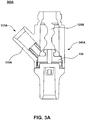
- Figures 3A-B depicts embodiments of cross-sectional views of needleless valve systems 300A-B. Needleless valve systems 300A-B are similar to needleless valve system 200, as described above.
- needleless valve system 300A includes stem 310A that protrudes from housing 340A.
- stem 310A protrudes from housing 340A to form a shape similar to a "Y.”
- stem 310A can protrude from any angle from housing 340A.
- Port 315A is configured to allow conveyance of another fluid into housing 340A.
- stem 310A is interfaces with a tube connected to an IV bag. Accordingly, fluid from the IV bag is able to flow through port 315A into housing 340A and subsequently to a patient.
- Needleless valve system 300B is similar to needleless valve system 300A. However, in one embodiment, stem 310B protrude perpendicularly from housing 340B to form a "T" shape. However, in various embodiments, stem 310B can protrude from any angle from housing 340B.
- Figure 4 depicts an embodiment of method 400 for assembling a needleless valve system.
- a selected valve is obtained by selecting a valve for the needleless valve assembly, wherein the selection is between a first type of valve or a second type of valve.
- a manufacturer of needleless valve systems has an inventory of positive displacement valves (e.g., positive displacement valve 120A) for assembly of positive displacement needleless valve systems and an inventory of negative displacement valves (e.g., negative displacement valve 120B) for assembly of negative displacement needleless valve systems.
- 500 positive displacement valves are obtained by selecting 500 positive displacement valves (rather than 500 negative displacement valves) to manufacture the 500 positive displacement needleless valve systems.
- a selected valve is obtained, wherein the selection is between a positive displacement valve (e.g., positive displacement valve 120A) and a negative displacement valve (e.g., negative displacement valve 120B).
- a positive displacement valve e.g., positive displacement valve 120A
- a negative displacement valve e.g., negative displacement valve 120B
- the selected valve is coupled to a base, wherein the base is suited to be coupled to either the first type of valve or the second type of valve.
- the selected valve e.g., positive displacement valve 120A
- base portion 130 is configured to be coupled to either a first type of valve (e.g., positive displacement valve 120A) or a second type of valve (e.g., negative displacement valve 120B).
- the selected valve is coupled to a single type of base.
- base portion 130 is utilized for both the assembly of a positive displacement needleless valve systems and the assembly of negative displacement needleless valve systems. Therefore, either positive displacement valve 120A is coupled to base portion 130 or negative displacement valve portion 120B is coupled to base portion 130.
- two different types of base portions are not required to assemble a positive displacement needleless valve system and a negative displacement needleless valve system.
- a base coupling feature of the selected valve is coupled to a valve coupling feature of the base.
- base coupling feature 125 is coupled to valve coupling feature 134.
- a snap-fit feature of the selected valve is coupled to a snap-fit feature of the base.
- the snap-fit feature of base coupling feature 125 is snapped around valve coupling feature 134.
- the base is coupled to a housing, wherein the valve is disposed in the housing of the needleless valve assembly.
- base portion 130 is coupled to housing 240, wherein positive displacement valve 120A is disposed in housing 240 of needleless valve assembly 200.
Landscapes
- Health & Medical Sciences (AREA)
- Heart & Thoracic Surgery (AREA)
- Hematology (AREA)
- Engineering & Computer Science (AREA)
- Anesthesiology (AREA)
- Biomedical Technology (AREA)
- Pulmonology (AREA)
- Life Sciences & Earth Sciences (AREA)
- Animal Behavior & Ethology (AREA)
- General Health & Medical Sciences (AREA)
- Public Health (AREA)
- Veterinary Medicine (AREA)
- Infusion, Injection, And Reservoir Apparatuses (AREA)
- Check Valves (AREA)
Applications Claiming Priority (2)
| Application Number | Priority Date | Filing Date | Title |
|---|---|---|---|
| US13/359,332 US9409007B2 (en) | 2012-01-26 | 2012-01-26 | Assembling a needleless valve system |
| PCT/US2013/021970 WO2013112352A1 (en) | 2012-01-26 | 2013-01-17 | Needleless valve system |
Publications (3)
| Publication Number | Publication Date |
|---|---|
| EP2806923A1 EP2806923A1 (en) | 2014-12-03 |
| EP2806923A4 EP2806923A4 (en) | 2015-07-15 |
| EP2806923B1 true EP2806923B1 (en) | 2020-02-26 |
Family
ID=48869457
Family Applications (1)
| Application Number | Title | Priority Date | Filing Date |
|---|---|---|---|
| EP13741365.4A Active EP2806923B1 (en) | 2012-01-26 | 2013-01-17 | Needleless valve system |
Country Status (6)
| Country | Link |
|---|---|
| US (1) | US9409007B2 (enExample) |
| EP (1) | EP2806923B1 (enExample) |
| JP (1) | JP6318092B2 (enExample) |
| AU (1) | AU2013212594B2 (enExample) |
| CA (1) | CA2862325C (enExample) |
| WO (1) | WO2013112352A1 (enExample) |
Families Citing this family (20)
| Publication number | Priority date | Publication date | Assignee | Title |
|---|---|---|---|---|
| US9168366B2 (en) | 2008-12-19 | 2015-10-27 | Icu Medical, Inc. | Medical connector with closeable luer connector |
| US8323249B2 (en) | 2009-08-14 | 2012-12-04 | The Regents Of The University Of Michigan | Integrated vascular delivery system |
| WO2011146769A2 (en) | 2010-05-19 | 2011-11-24 | Tangent Medical Technologies Llc | Integrated vascular delivery system |
| US8814833B2 (en) | 2010-05-19 | 2014-08-26 | Tangent Medical Technologies Llc | Safety needle system operable with a medical device |
| AU2012304344B2 (en) | 2011-09-09 | 2016-02-04 | Icu Medical, Inc. | Medical connectors with fluid-resistant mating interfaces |
| US9162029B2 (en) * | 2012-11-09 | 2015-10-20 | Carefusion 303, Inc. | Tailless needleless valve system |
| AU2013342123B2 (en) | 2012-11-12 | 2018-08-02 | Icu Medical, Inc. | Medical connector |
| US9089682B2 (en) | 2013-03-14 | 2015-07-28 | Carefusion 303, Inc. | Needleless connector with support member |
| US9144672B2 (en) * | 2013-03-13 | 2015-09-29 | Carefusion 303, Inc. | Needleless connector with compressible valve |
| CN105163796B (zh) | 2013-03-15 | 2018-06-01 | Icu医学有限公司 | 医用连接器 |
| EP3079739B1 (en) | 2013-12-11 | 2023-02-22 | ICU Medical, Inc. | Check valve |
| JP6461174B2 (ja) | 2014-02-04 | 2019-01-30 | アイシーユー・メディカル・インコーポレーテッド | 自己プライミングシステムおよび自己プライミング方法 |
| USD786427S1 (en) | 2014-12-03 | 2017-05-09 | Icu Medical, Inc. | Fluid manifold |
| USD793551S1 (en) | 2014-12-03 | 2017-08-01 | Icu Medical, Inc. | Fluid manifold |
| ES2792025T3 (es) * | 2015-10-28 | 2020-11-06 | Carefusion 303 Inc | Dispositivo de acceso IV cerrado con puerto y conector sin aguja |
| CN106181360B (zh) * | 2016-07-18 | 2021-11-02 | 湖南千山制药机械股份有限公司 | 蝶翼式采血针的组装方法 |
| EP3784323A1 (en) * | 2018-04-24 | 2021-03-03 | CareFusion 303, Inc. | Self-flushing connector |
| US20220355092A1 (en) * | 2021-05-04 | 2022-11-10 | Carefusion 303, Inc. | Needleless connector having check valve with asymmetric valve design and primary seal support |
| US12208230B2 (en) * | 2022-11-09 | 2025-01-28 | Carefusion 303, Inc. | Fluid connector assembly that seals flow paths when the connectors are disconnected |
| USD1105422S1 (en) | 2024-02-09 | 2025-12-09 | Icu Medical, Inc. | Medical connector cover |
Family Cites Families (10)
| Publication number | Priority date | Publication date | Assignee | Title |
|---|---|---|---|---|
| WO1995015195A1 (en) | 1993-11-30 | 1995-06-08 | Medex, Inc. | Plastic needleless valve housing for standard male luer locks |
| EP1639286B1 (en) * | 2003-06-17 | 2014-12-03 | Filtertek Inc. | Fluid handling device |
| US7771383B2 (en) * | 2004-10-22 | 2010-08-10 | Medegen, Inc. | Fluid control device with valve and methods of use |
| US7241285B1 (en) | 2004-12-06 | 2007-07-10 | Medical Ventures, Inc. | Medical site connection |
| US9695953B2 (en) * | 2006-02-14 | 2017-07-04 | B. Braun Medical Inc. | Needleless access port valves |
| WO2008064173A2 (en) * | 2006-11-17 | 2008-05-29 | B. Braun Medical Inc. | Antimicrobial silicone rubber injection port valves |
| US20100036330A1 (en) * | 2008-08-11 | 2010-02-11 | Baxter International Inc. | Needleless connector with displacement correction |
| US8074964B2 (en) | 2008-09-05 | 2011-12-13 | Carefusion 303, Inc. | Luer activated medical connector having a low priming volume |
| US8636720B2 (en) * | 2009-11-16 | 2014-01-28 | Carefusion 303, Inc. | Needleless access connectors and valve elements therefor |
| US8298196B1 (en) | 2010-03-24 | 2012-10-30 | Mansour George M | Needleless access connector and method of use |
-
2012
- 2012-01-26 US US13/359,332 patent/US9409007B2/en active Active
-
2013
- 2013-01-17 JP JP2014554743A patent/JP6318092B2/ja active Active
- 2013-01-17 WO PCT/US2013/021970 patent/WO2013112352A1/en not_active Ceased
- 2013-01-17 AU AU2013212594A patent/AU2013212594B2/en active Active
- 2013-01-17 EP EP13741365.4A patent/EP2806923B1/en active Active
- 2013-01-17 CA CA2862325A patent/CA2862325C/en active Active
Non-Patent Citations (1)
| Title |
|---|
| None * |
Also Published As
| Publication number | Publication date |
|---|---|
| WO2013112352A1 (en) | 2013-08-01 |
| EP2806923A1 (en) | 2014-12-03 |
| AU2013212594B2 (en) | 2017-04-20 |
| AU2013212594A1 (en) | 2014-07-24 |
| CA2862325A1 (en) | 2013-08-01 |
| JP2015505485A (ja) | 2015-02-23 |
| EP2806923A4 (en) | 2015-07-15 |
| JP6318092B2 (ja) | 2018-04-25 |
| US9409007B2 (en) | 2016-08-09 |
| CA2862325C (en) | 2020-10-06 |
| US20130193359A1 (en) | 2013-08-01 |
Similar Documents
| Publication | Publication Date | Title |
|---|---|---|
| EP2806923B1 (en) | Needleless valve system | |
| EP3348296B1 (en) | Compressible cannula valve and method for controlling fluid flow in a compressible cannula valve | |
| EP2550057B1 (en) | New needleless access connector and method of use | |
| EP3459587B1 (en) | Needleless connector | |
| EP2777759B1 (en) | Needleless connector with flexible valve | |
| EP2432546B1 (en) | Intravascular valve component with improved valve positioning | |
| EP3349840B1 (en) | Safety iv catheter with molded-open blood control valve | |
| CN105120943B (zh) | 输送装置的阀 | |
| CN105007975B (zh) | 帽盖 | |
| CN108392730B (zh) | 无尾式无针阀门系统 | |
| EP4126185B1 (en) | Check valve with flash seal | |
| US7484529B2 (en) | Connector | |
| JP2005137407A (ja) | 接続具 |
Legal Events
| Date | Code | Title | Description |
|---|---|---|---|
| PUAI | Public reference made under article 153(3) epc to a published international application that has entered the european phase |
Free format text: ORIGINAL CODE: 0009012 |
|
| 17P | Request for examination filed |
Effective date: 20140822 |
|
| AK | Designated contracting states |
Kind code of ref document: A1 Designated state(s): AL AT BE BG CH CY CZ DE DK EE ES FI FR GB GR HR HU IE IS IT LI LT LU LV MC MK MT NL NO PL PT RO RS SE SI SK SM TR |
|
| DAX | Request for extension of the european patent (deleted) | ||
| RA4 | Supplementary search report drawn up and despatched (corrected) |
Effective date: 20150616 |
|
| RIC1 | Information provided on ipc code assigned before grant |
Ipc: A61M 5/30 20060101AFI20150610BHEP Ipc: A61M 39/22 20060101ALI20150610BHEP Ipc: A61M 39/24 20060101ALI20150610BHEP Ipc: A61M 39/26 20060101ALI20150610BHEP Ipc: A61M 39/10 20060101ALI20150610BHEP |
|
| STAA | Information on the status of an ep patent application or granted ep patent |
Free format text: STATUS: EXAMINATION IS IN PROGRESS |
|
| 17Q | First examination report despatched |
Effective date: 20190425 |
|
| GRAP | Despatch of communication of intention to grant a patent |
Free format text: ORIGINAL CODE: EPIDOSNIGR1 |
|
| STAA | Information on the status of an ep patent application or granted ep patent |
Free format text: STATUS: GRANT OF PATENT IS INTENDED |
|
| INTG | Intention to grant announced |
Effective date: 20190822 |
|
| GRAS | Grant fee paid |
Free format text: ORIGINAL CODE: EPIDOSNIGR3 |
|
| GRAA | (expected) grant |
Free format text: ORIGINAL CODE: 0009210 |
|
| STAA | Information on the status of an ep patent application or granted ep patent |
Free format text: STATUS: THE PATENT HAS BEEN GRANTED |
|
| AK | Designated contracting states |
Kind code of ref document: B1 Designated state(s): AL AT BE BG CH CY CZ DE DK EE ES FI FR GB GR HR HU IE IS IT LI LT LU LV MC MK MT NL NO PL PT RO RS SE SI SK SM TR |
|
| REG | Reference to a national code |
Ref country code: GB Ref legal event code: FG4D |
|
| REG | Reference to a national code |
Ref country code: CH Ref legal event code: EP |
|
| REG | Reference to a national code |
Ref country code: AT Ref legal event code: REF Ref document number: 1236873 Country of ref document: AT Kind code of ref document: T Effective date: 20200315 |
|
| REG | Reference to a national code |
Ref country code: IE Ref legal event code: FG4D |
|
| REG | Reference to a national code |
Ref country code: DE Ref legal event code: R096 Ref document number: 602013066235 Country of ref document: DE |
|
| REG | Reference to a national code |
Ref country code: DE Ref legal event code: R082 Ref document number: 602013066235 Country of ref document: DE Representative=s name: EPPING HERMANN FISCHER PATENTANWALTSGESELLSCHA, DE |
|
| PG25 | Lapsed in a contracting state [announced via postgrant information from national office to epo] |
Ref country code: NO Free format text: LAPSE BECAUSE OF FAILURE TO SUBMIT A TRANSLATION OF THE DESCRIPTION OR TO PAY THE FEE WITHIN THE PRESCRIBED TIME-LIMIT Effective date: 20200526 Ref country code: FI Free format text: LAPSE BECAUSE OF FAILURE TO SUBMIT A TRANSLATION OF THE DESCRIPTION OR TO PAY THE FEE WITHIN THE PRESCRIBED TIME-LIMIT Effective date: 20200226 Ref country code: RS Free format text: LAPSE BECAUSE OF FAILURE TO SUBMIT A TRANSLATION OF THE DESCRIPTION OR TO PAY THE FEE WITHIN THE PRESCRIBED TIME-LIMIT Effective date: 20200226 |
|
| REG | Reference to a national code |
Ref country code: NL Ref legal event code: MP Effective date: 20200226 |
|
| REG | Reference to a national code |
Ref country code: LT Ref legal event code: MG4D |
|
| PG25 | Lapsed in a contracting state [announced via postgrant information from national office to epo] |
Ref country code: GR Free format text: LAPSE BECAUSE OF FAILURE TO SUBMIT A TRANSLATION OF THE DESCRIPTION OR TO PAY THE FEE WITHIN THE PRESCRIBED TIME-LIMIT Effective date: 20200527 Ref country code: BG Free format text: LAPSE BECAUSE OF FAILURE TO SUBMIT A TRANSLATION OF THE DESCRIPTION OR TO PAY THE FEE WITHIN THE PRESCRIBED TIME-LIMIT Effective date: 20200526 Ref country code: LV Free format text: LAPSE BECAUSE OF FAILURE TO SUBMIT A TRANSLATION OF THE DESCRIPTION OR TO PAY THE FEE WITHIN THE PRESCRIBED TIME-LIMIT Effective date: 20200226 Ref country code: SE Free format text: LAPSE BECAUSE OF FAILURE TO SUBMIT A TRANSLATION OF THE DESCRIPTION OR TO PAY THE FEE WITHIN THE PRESCRIBED TIME-LIMIT Effective date: 20200226 Ref country code: IS Free format text: LAPSE BECAUSE OF FAILURE TO SUBMIT A TRANSLATION OF THE DESCRIPTION OR TO PAY THE FEE WITHIN THE PRESCRIBED TIME-LIMIT Effective date: 20200626 Ref country code: HR Free format text: LAPSE BECAUSE OF FAILURE TO SUBMIT A TRANSLATION OF THE DESCRIPTION OR TO PAY THE FEE WITHIN THE PRESCRIBED TIME-LIMIT Effective date: 20200226 |
|
| PG25 | Lapsed in a contracting state [announced via postgrant information from national office to epo] |
Ref country code: NL Free format text: LAPSE BECAUSE OF FAILURE TO SUBMIT A TRANSLATION OF THE DESCRIPTION OR TO PAY THE FEE WITHIN THE PRESCRIBED TIME-LIMIT Effective date: 20200226 |
|
| PG25 | Lapsed in a contracting state [announced via postgrant information from national office to epo] |
Ref country code: SM Free format text: LAPSE BECAUSE OF FAILURE TO SUBMIT A TRANSLATION OF THE DESCRIPTION OR TO PAY THE FEE WITHIN THE PRESCRIBED TIME-LIMIT Effective date: 20200226 Ref country code: EE Free format text: LAPSE BECAUSE OF FAILURE TO SUBMIT A TRANSLATION OF THE DESCRIPTION OR TO PAY THE FEE WITHIN THE PRESCRIBED TIME-LIMIT Effective date: 20200226 Ref country code: DK Free format text: LAPSE BECAUSE OF FAILURE TO SUBMIT A TRANSLATION OF THE DESCRIPTION OR TO PAY THE FEE WITHIN THE PRESCRIBED TIME-LIMIT Effective date: 20200226 Ref country code: ES Free format text: LAPSE BECAUSE OF FAILURE TO SUBMIT A TRANSLATION OF THE DESCRIPTION OR TO PAY THE FEE WITHIN THE PRESCRIBED TIME-LIMIT Effective date: 20200226 Ref country code: PT Free format text: LAPSE BECAUSE OF FAILURE TO SUBMIT A TRANSLATION OF THE DESCRIPTION OR TO PAY THE FEE WITHIN THE PRESCRIBED TIME-LIMIT Effective date: 20200719 Ref country code: CZ Free format text: LAPSE BECAUSE OF FAILURE TO SUBMIT A TRANSLATION OF THE DESCRIPTION OR TO PAY THE FEE WITHIN THE PRESCRIBED TIME-LIMIT Effective date: 20200226 Ref country code: LT Free format text: LAPSE BECAUSE OF FAILURE TO SUBMIT A TRANSLATION OF THE DESCRIPTION OR TO PAY THE FEE WITHIN THE PRESCRIBED TIME-LIMIT Effective date: 20200226 Ref country code: RO Free format text: LAPSE BECAUSE OF FAILURE TO SUBMIT A TRANSLATION OF THE DESCRIPTION OR TO PAY THE FEE WITHIN THE PRESCRIBED TIME-LIMIT Effective date: 20200226 Ref country code: SK Free format text: LAPSE BECAUSE OF FAILURE TO SUBMIT A TRANSLATION OF THE DESCRIPTION OR TO PAY THE FEE WITHIN THE PRESCRIBED TIME-LIMIT Effective date: 20200226 |
|
| REG | Reference to a national code |
Ref country code: AT Ref legal event code: MK05 Ref document number: 1236873 Country of ref document: AT Kind code of ref document: T Effective date: 20200226 |
|
| REG | Reference to a national code |
Ref country code: DE Ref legal event code: R097 Ref document number: 602013066235 Country of ref document: DE |
|
| PLBE | No opposition filed within time limit |
Free format text: ORIGINAL CODE: 0009261 |
|
| STAA | Information on the status of an ep patent application or granted ep patent |
Free format text: STATUS: NO OPPOSITION FILED WITHIN TIME LIMIT |
|
| PG25 | Lapsed in a contracting state [announced via postgrant information from national office to epo] |
Ref country code: AT Free format text: LAPSE BECAUSE OF FAILURE TO SUBMIT A TRANSLATION OF THE DESCRIPTION OR TO PAY THE FEE WITHIN THE PRESCRIBED TIME-LIMIT Effective date: 20200226 Ref country code: IT Free format text: LAPSE BECAUSE OF FAILURE TO SUBMIT A TRANSLATION OF THE DESCRIPTION OR TO PAY THE FEE WITHIN THE PRESCRIBED TIME-LIMIT Effective date: 20200226 |
|
| 26N | No opposition filed |
Effective date: 20201127 |
|
| PG25 | Lapsed in a contracting state [announced via postgrant information from national office to epo] |
Ref country code: PL Free format text: LAPSE BECAUSE OF FAILURE TO SUBMIT A TRANSLATION OF THE DESCRIPTION OR TO PAY THE FEE WITHIN THE PRESCRIBED TIME-LIMIT Effective date: 20200226 Ref country code: SI Free format text: LAPSE BECAUSE OF FAILURE TO SUBMIT A TRANSLATION OF THE DESCRIPTION OR TO PAY THE FEE WITHIN THE PRESCRIBED TIME-LIMIT Effective date: 20200226 |
|
| PG25 | Lapsed in a contracting state [announced via postgrant information from national office to epo] |
Ref country code: MC Free format text: LAPSE BECAUSE OF FAILURE TO SUBMIT A TRANSLATION OF THE DESCRIPTION OR TO PAY THE FEE WITHIN THE PRESCRIBED TIME-LIMIT Effective date: 20200226 |
|
| REG | Reference to a national code |
Ref country code: CH Ref legal event code: PL |
|
| PG25 | Lapsed in a contracting state [announced via postgrant information from national office to epo] |
Ref country code: LU Free format text: LAPSE BECAUSE OF NON-PAYMENT OF DUE FEES Effective date: 20210117 |
|
| PG25 | Lapsed in a contracting state [announced via postgrant information from national office to epo] |
Ref country code: LI Free format text: LAPSE BECAUSE OF NON-PAYMENT OF DUE FEES Effective date: 20210131 Ref country code: CH Free format text: LAPSE BECAUSE OF NON-PAYMENT OF DUE FEES Effective date: 20210131 |
|
| PG25 | Lapsed in a contracting state [announced via postgrant information from national office to epo] |
Ref country code: IE Free format text: LAPSE BECAUSE OF NON-PAYMENT OF DUE FEES Effective date: 20210117 |
|
| PG25 | Lapsed in a contracting state [announced via postgrant information from national office to epo] |
Ref country code: HU Free format text: LAPSE BECAUSE OF FAILURE TO SUBMIT A TRANSLATION OF THE DESCRIPTION OR TO PAY THE FEE WITHIN THE PRESCRIBED TIME-LIMIT; INVALID AB INITIO Effective date: 20130117 |
|
| PG25 | Lapsed in a contracting state [announced via postgrant information from national office to epo] |
Ref country code: CY Free format text: LAPSE BECAUSE OF FAILURE TO SUBMIT A TRANSLATION OF THE DESCRIPTION OR TO PAY THE FEE WITHIN THE PRESCRIBED TIME-LIMIT Effective date: 20200226 |
|
| PG25 | Lapsed in a contracting state [announced via postgrant information from national office to epo] |
Ref country code: MK Free format text: LAPSE BECAUSE OF FAILURE TO SUBMIT A TRANSLATION OF THE DESCRIPTION OR TO PAY THE FEE WITHIN THE PRESCRIBED TIME-LIMIT Effective date: 20200226 |
|
| PG25 | Lapsed in a contracting state [announced via postgrant information from national office to epo] |
Ref country code: MT Free format text: LAPSE BECAUSE OF FAILURE TO SUBMIT A TRANSLATION OF THE DESCRIPTION OR TO PAY THE FEE WITHIN THE PRESCRIBED TIME-LIMIT Effective date: 20200226 |
|
| PG25 | Lapsed in a contracting state [announced via postgrant information from national office to epo] |
Ref country code: TR Free format text: LAPSE BECAUSE OF FAILURE TO SUBMIT A TRANSLATION OF THE DESCRIPTION OR TO PAY THE FEE WITHIN THE PRESCRIBED TIME-LIMIT Effective date: 20200226 |
|
| PGFP | Annual fee paid to national office [announced via postgrant information from national office to epo] |
Ref country code: GB Payment date: 20251220 Year of fee payment: 14 |
|
| PGFP | Annual fee paid to national office [announced via postgrant information from national office to epo] |
Ref country code: FR Payment date: 20251218 Year of fee payment: 14 |
|
| PGFP | Annual fee paid to national office [announced via postgrant information from national office to epo] |
Ref country code: BE Payment date: 20251217 Year of fee payment: 14 |
|
| PGFP | Annual fee paid to national office [announced via postgrant information from national office to epo] |
Ref country code: DE Payment date: 20251217 Year of fee payment: 14 |