EP3349840B1 - Safety iv catheter with molded-open blood control valve - Google Patents
Safety iv catheter with molded-open blood control valve Download PDFInfo
- Publication number
- EP3349840B1 EP3349840B1 EP16847438.5A EP16847438A EP3349840B1 EP 3349840 B1 EP3349840 B1 EP 3349840B1 EP 16847438 A EP16847438 A EP 16847438A EP 3349840 B1 EP3349840 B1 EP 3349840B1
- Authority
- EP
- European Patent Office
- Prior art keywords
- catheter
- catheter hub
- valve
- septum
- needle
- Prior art date
- Legal status (The legal status is an assumption and is not a legal conclusion. Google has not performed a legal analysis and makes no representation as to the accuracy of the status listed.)
- Active
Links
- 239000008280 blood Substances 0.000 title description 8
- 210000004369 blood Anatomy 0.000 title description 8
- 239000012530 fluid Substances 0.000 claims description 42
- 230000006835 compression Effects 0.000 claims description 23
- 238000007906 compression Methods 0.000 claims description 23
- 238000003860 storage Methods 0.000 claims description 5
- 230000007246 mechanism Effects 0.000 description 29
- 238000007789 sealing Methods 0.000 description 15
- 239000013013 elastic material Substances 0.000 description 6
- 210000003462 vein Anatomy 0.000 description 6
- 230000008901 benefit Effects 0.000 description 4
- 238000004519 manufacturing process Methods 0.000 description 3
- 239000000463 material Substances 0.000 description 3
- 230000000712 assembly Effects 0.000 description 2
- 238000000429 assembly Methods 0.000 description 2
- 230000001010 compromised effect Effects 0.000 description 2
- 238000000034 method Methods 0.000 description 2
- 230000037361 pathway Effects 0.000 description 2
- 230000001105 regulatory effect Effects 0.000 description 2
- 229920002379 silicone rubber Polymers 0.000 description 2
- 239000004945 silicone rubber Substances 0.000 description 2
- 230000002792 vascular Effects 0.000 description 2
- FAPWRFPIFSIZLT-UHFFFAOYSA-M Sodium chloride Chemical compound [Na+].[Cl-] FAPWRFPIFSIZLT-UHFFFAOYSA-M 0.000 description 1
- 239000000853 adhesive Substances 0.000 description 1
- 230000001070 adhesive effect Effects 0.000 description 1
- 230000003190 augmentative effect Effects 0.000 description 1
- 230000004888 barrier function Effects 0.000 description 1
- 238000004891 communication Methods 0.000 description 1
- 150000001875 compounds Chemical class 0.000 description 1
- 238000010276 construction Methods 0.000 description 1
- 238000005520 cutting process Methods 0.000 description 1
- 230000007423 decrease Effects 0.000 description 1
- 230000000694 effects Effects 0.000 description 1
- 238000001990 intravenous administration Methods 0.000 description 1
- 238000003754 machining Methods 0.000 description 1
- 239000012528 membrane Substances 0.000 description 1
- 239000000203 mixture Substances 0.000 description 1
- 238000012986 modification Methods 0.000 description 1
- 230000004048 modification Effects 0.000 description 1
- 238000012544 monitoring process Methods 0.000 description 1
- 235000016709 nutrition Nutrition 0.000 description 1
- 239000002861 polymer material Substances 0.000 description 1
- 230000008569 process Effects 0.000 description 1
- 230000007704 transition Effects 0.000 description 1
- 238000013022 venting Methods 0.000 description 1
- 238000003466 welding Methods 0.000 description 1
Images


Classifications
-
- A—HUMAN NECESSITIES
- A61—MEDICAL OR VETERINARY SCIENCE; HYGIENE
- A61M—DEVICES FOR INTRODUCING MEDIA INTO, OR ONTO, THE BODY; DEVICES FOR TRANSDUCING BODY MEDIA OR FOR TAKING MEDIA FROM THE BODY; DEVICES FOR PRODUCING OR ENDING SLEEP OR STUPOR
- A61M39/00—Tubes, tube connectors, tube couplings, valves, access sites or the like, specially adapted for medical use
- A61M39/22—Valves or arrangement of valves
- A61M39/26—Valves closing automatically on disconnecting the line and opening on reconnection thereof
-
- A—HUMAN NECESSITIES
- A61—MEDICAL OR VETERINARY SCIENCE; HYGIENE
- A61M—DEVICES FOR INTRODUCING MEDIA INTO, OR ONTO, THE BODY; DEVICES FOR TRANSDUCING BODY MEDIA OR FOR TAKING MEDIA FROM THE BODY; DEVICES FOR PRODUCING OR ENDING SLEEP OR STUPOR
- A61M25/00—Catheters; Hollow probes
- A61M25/01—Introducing, guiding, advancing, emplacing or holding catheters
- A61M25/06—Body-piercing guide needles or the like
- A61M25/0606—"Over-the-needle" catheter assemblies, e.g. I.V. catheters
-
- A—HUMAN NECESSITIES
- A61—MEDICAL OR VETERINARY SCIENCE; HYGIENE
- A61M—DEVICES FOR INTRODUCING MEDIA INTO, OR ONTO, THE BODY; DEVICES FOR TRANSDUCING BODY MEDIA OR FOR TAKING MEDIA FROM THE BODY; DEVICES FOR PRODUCING OR ENDING SLEEP OR STUPOR
- A61M39/00—Tubes, tube connectors, tube couplings, valves, access sites or the like, specially adapted for medical use
- A61M39/02—Access sites
- A61M39/06—Haemostasis valves, i.e. gaskets sealing around a needle, catheter or the like, closing on removal thereof
- A61M39/0606—Haemostasis valves, i.e. gaskets sealing around a needle, catheter or the like, closing on removal thereof without means for adjusting the seal opening or pressure
-
- A—HUMAN NECESSITIES
- A61—MEDICAL OR VETERINARY SCIENCE; HYGIENE
- A61M—DEVICES FOR INTRODUCING MEDIA INTO, OR ONTO, THE BODY; DEVICES FOR TRANSDUCING BODY MEDIA OR FOR TAKING MEDIA FROM THE BODY; DEVICES FOR PRODUCING OR ENDING SLEEP OR STUPOR
- A61M39/00—Tubes, tube connectors, tube couplings, valves, access sites or the like, specially adapted for medical use
- A61M39/02—Access sites
- A61M39/06—Haemostasis valves, i.e. gaskets sealing around a needle, catheter or the like, closing on removal thereof
- A61M2039/062—Haemostasis valves, i.e. gaskets sealing around a needle, catheter or the like, closing on removal thereof used with a catheter
-
- A—HUMAN NECESSITIES
- A61—MEDICAL OR VETERINARY SCIENCE; HYGIENE
- A61M—DEVICES FOR INTRODUCING MEDIA INTO, OR ONTO, THE BODY; DEVICES FOR TRANSDUCING BODY MEDIA OR FOR TAKING MEDIA FROM THE BODY; DEVICES FOR PRODUCING OR ENDING SLEEP OR STUPOR
- A61M39/00—Tubes, tube connectors, tube couplings, valves, access sites or the like, specially adapted for medical use
- A61M39/02—Access sites
- A61M39/06—Haemostasis valves, i.e. gaskets sealing around a needle, catheter or the like, closing on removal thereof
- A61M2039/0633—Haemostasis valves, i.e. gaskets sealing around a needle, catheter or the like, closing on removal thereof the seal being a passive seal made of a resilient material with or without an opening
- A61M2039/064—Slit-valve
-
- A—HUMAN NECESSITIES
- A61—MEDICAL OR VETERINARY SCIENCE; HYGIENE
- A61M—DEVICES FOR INTRODUCING MEDIA INTO, OR ONTO, THE BODY; DEVICES FOR TRANSDUCING BODY MEDIA OR FOR TAKING MEDIA FROM THE BODY; DEVICES FOR PRODUCING OR ENDING SLEEP OR STUPOR
- A61M39/00—Tubes, tube connectors, tube couplings, valves, access sites or the like, specially adapted for medical use
- A61M39/22—Valves or arrangement of valves
- A61M39/24—Check- or non-return valves
- A61M2039/2433—Valve comprising a resilient or deformable element, e.g. flap valve, deformable disc
-
- A—HUMAN NECESSITIES
- A61—MEDICAL OR VETERINARY SCIENCE; HYGIENE
- A61M—DEVICES FOR INTRODUCING MEDIA INTO, OR ONTO, THE BODY; DEVICES FOR TRANSDUCING BODY MEDIA OR FOR TAKING MEDIA FROM THE BODY; DEVICES FOR PRODUCING OR ENDING SLEEP OR STUPOR
- A61M5/00—Devices for bringing media into the body in a subcutaneous, intra-vascular or intramuscular way; Accessories therefor, e.g. filling or cleaning devices, arm-rests
- A61M5/178—Syringes
- A61M5/31—Details
- A61M5/32—Needles; Details of needles pertaining to their connection with syringe or hub; Accessories for bringing the needle into, or holding the needle on, the body; Devices for protection of needles
- A61M5/3205—Apparatus for removing or disposing of used needles or syringes, e.g. containers; Means for protection against accidental injuries from used needles
- A61M5/321—Means for protection against accidental injuries by used needles
- A61M5/3243—Means for protection against accidental injuries by used needles being axially-extensible, e.g. protective sleeves coaxially slidable on the syringe barrel
- A61M5/3273—Means for protection against accidental injuries by used needles being axially-extensible, e.g. protective sleeves coaxially slidable on the syringe barrel freely sliding on needle shaft without connection to syringe or needle
Definitions
- Various exemplary embodiments of the invention relate to catheter assemblies.
- Catheter assemblies are used to place a catheter into the vascular system of a patient. Once in place, catheters such as intravenous catheters may be used to infuse fluids including normal saline, medicinal compounds, and/or nutritional compositions into a patient in need of such treatment. Catheters additionally enable the removal of fluids from the circulatory system and monitoring of conditions within the vascular system of the patient.
- US 2015/202421 A1 describes a ported catheter adapter having a combined blood control valve and port valve, wherein the combined valve comprises one or more vents that permit the passage of air and prevent the passage of fluids.
- the one or more vents in US 2015/202421 A1 are located on the outer surface of the valve so as to avoid being overlapped with the pathway of the side port. As such, fluid communication between the side port and the vents is prevented.
- Various venting configurations are provided in US 2015/202421 A1 .
- the device of US 2015/202421 A1 further includes a valve actuator that is advanced through a slit in the membrane of the valve to provide a pathway for fluid to bypass the valve.
- septums in the prior art are closed in their natural state and need to be pierced or otherwise engaged to be opened.
- the septum disclosed herein is open in its natural state and is closed by its housing or an external force, for example. Such a septum provides a plurality of advantages disclosed herein.
- the catheter assembly includes a ported catheter where the catheter hub has a side port.
- the septum disclosed herein is advantageously able to regulate fluid flow from the catheter and the side port simultaneously and independently.
- the catheter assembly disclosed herein includes a needle having a reduced diameter that engages the septum during storage to advantageously minimize compression setting.
- the embodiments of the catheter assembly disclosed herein provide advantages of fewer components, improved manufacturing and assembly and more efficient and more reliable operation.
- a catheter assembly comprising a catheter, a needle having a sharp distal tip disposed within the catheter, and a catheter hub connected to the catheter having the needle passing therethrough, the catheter hub including a valve having a preformed opening that selectively permits or blocks a flow of fluid through the catheter, a first inner diameter that closes the valve, and a second inner diameter larger than the first inner diameter, the second inner diameter opening the valve, wherein the valve is in an open position upon compressing the valve into engagement with the second inner diameter of the catheter hub, and the valve is in a closed position upon releasing the valve to engage the first inner diameter of the catheter hub.
- a catheter assembly comprising a catheter, a needle having a sharp distal tip disposed within the catheter, a catheter hub connected to the catheter having the needle passing therethrough, the catheter hub including a valve having a preformed opening that selectively permits or blocks a flow of fluid through the catheter, a first inner diameter that closes the valve, and a second inner diameter larger than the first inner diameter, the second inner diameter opening the valve, and a needle shield that houses the needle, wherein the valve is in an open position upon engaging the needle shield to the catheter hub and compressing the valve into the second inner diameter of the catheter hub, and the valve is in a closed position upon disengaging the needle shield from the catheter assembly, thus releasing the valve to engage the first inner diameter of the catheter hub.
- a catheter assembly 10, as shown in Figure 1 includes a hollow introducer needle 12, a catheter hub 14, and a needle hub 16.
- the introducer needle 12 has a sharpened distal tip 13 and extends through the catheter hub 14.
- a flexible catheter tube 18 extends from the distal end of the catheter hub 14, with the needle 12 passing through the catheter tube 18.
- the flexible catheter tube 18 extends through the catheter opening. Initially, the needle 12 is inserted into a patient's vein. The catheter tube 18 is pushed along the needle 12 and into the vein following the needle 12. After the catheter tube 18 is inserted, the needle 12 is removed from the patient's vein and the catheter hub 14, leaving the catheter tube 18 in the patient as the needle 12 is discarded.
- FIG. 2 illustrates a cross-sectional view of an exemplary catheter hub assembly.
- the catheter hub assembly preferably includes a blood control valve 19 that includes a septum 20 and a compressible section such as a bellows 24, for example.
- the septum 20 is positioned in the catheter hub 28 and functions as a valve that forms a fluid-tight seal and selectively admits fluid to or from the flexible catheter tube 18. In other words, the valve selectively permits or blocks the flow of fluid through the flexible catheter tube 18.
- the septum 20 may be used in any of the embodiments discussed herein. Other septum configurations may be used as would be understood by one of ordinary skill in the art.
- the septum 20 is made of an elastic material to form the valve, for example silicone rubber. Other elastic materials may be used and non-elastic materials may be incorporated in the septum 20 as needed.
- the septum 20 comprises a preformed opening 22 or a molded-open slit.
- the preformed opening 22 of the septum 20 is preferably formed when the septum 20 is originally manufactured or in a subsequent machining or cutting operation. Accordingly, when the septum 20 is in its natural, uncompressed, free or relaxed state, the preformed opening 22 is open, thus placing the septum 20 in an open position and acting as an open fluid channel.
- the preformed opening 22 closes and seals to place the septum 20 in a closed position.
- septums in the prior art are closed in their natural state and need to be pierced, deformed or otherwise engaged to be opened.
- the septum 20 according to this embodiment is open in its natural state and is engaged to be closed.
- the septum 20 includes a bellows 24 that acts as a spring member.
- the axial spring of the bellows 24 can be simply a tube or can preferably include molded undulations or any other shape that allow the bellows 24 to resiliently compress in a predictable manner and still provide enough spring force for the septum 20 to operate.
- the bellows 24 is expanded in its natural state and compressed during operation to allow the septum 20 to move between the open and closed positions.
- the bellows 24 is preferably made of an elastic material, for example silicone rubber. Other elastic materials may be used and non-elastic materials may be incorporated in the bellows 24 as needed. According to one embodiment, the bellows 24 can be replaced or augmented by a spring member such as a coil spring and used in a catheter hub assembly to cooperate with the preformed opening 22 of the septum 20.
- a spring member such as a coil spring
- the septum 20 further includes a mounting surface 26.
- the mounting surface 26 secures the septum 20 at a position within the catheter hub assembly. Specifically, the mounting surface 26 is more rigid compared to the rest of the septum 20. The mounting surface 26 also expands in the inner diameter of the catheter hub 28. Such expansion provides a clamping force to secure the septum 20 and increased friction to prevent the septum 20 from being displaced.
- the bellows 24 is disposed between the mounting surface 26 and the preformed opening 22. Thus, after securing the mounting surface 26 of the septum 20, the septum 20 can operate between the relaxed and compressed positions.
- a distal end of the catheter hub 28 includes a catheter opening and a proximal end includes a Luer connector opening.
- the inner surface at the proximal end of the catheter hub 28 surrounds a channel that permits fluid passage through the catheter hub 28.
- the outer surface of the catheter hub 28 includes one or more projections to secure a Luer connector 34 to the catheter hub 28.
- the projections may form a threaded connection with the Luer connector 34 or they may connect to the Luer connector 34 through a snap fit or other twisting connection.
- Luer connectors 34 utilize a slip fit into the catheter hub 28.
- the Luer connector 34 travels a significant distance into the catheter hub 28 prior to contacting the septum 20.
- the extended inner diameter at the proximal end of the catheter hub 28 advantageously allows the Luer connector 34 to be centered in the catheter assembly.
- the catheter hub 28 may be made from a polymer material that is transparent or semi-transparent so that fluid flow through the catheter hub may be observed by a user or it may be made from an opaque material.
- the catheter hub 28 includes various inner diameters that interact with the septum 20 to provide effective operation.
- the catheter hub 28 includes a free diameter 30 and a compression diameter 32.
- the free diameter 30 is larger than the compression diameter 32.
- the free diameter 30 is preferably connected to the compression diameter 32 by a chamfered surface 31.
- the septum 20 is moved from the closed position to the open position by the Luer connector 34, for example.
- the Luer connector 34 is supported and centered by the inner diameter at the distal end of the catheter hub prior to interacting with the septum 20.
- the Luer connector 34 initially contacts the septum 20
- the surface surrounding the preformed opening 22 of the septum 20 is disposed in the compression diameter 32 and/or the chamfered surface 31 of the catheter hub 28.
- the septum 20 is in the closed position where the preformed opening 22 is closed and sealed.
- a user can push the Luer connector 34 into the catheter hub 28, which pushes the surface surrounding the preformed opening 22 of the septum 20 into a free diameter 30 of the catheter hub 28 while axially compressing the bellows 24.
- the septum 20 expands radially, causing the preformed opening 22 to open and allowing a path for fluid to flow.
- the septum 20 is compressed axially at the bellows 24 to create an increased reacting axial force.
- the bellows 24 of the septum 20 expands and causes the surface surrounding the preformed opening 22 of the septum 20 to enter into the chamfered surface 31 and/or the compression diameter 32 of the catheter hub 28 and enter into the closed position.
- the bellows 24 preferably continues to be partially axially compressed to create a force so that the septum 20 establishes a sealing surface with the free diameter 30, the chamfered surface 31 and the compression diameter 32.
- the septum 20 does not only operate between a fully relaxed position and a fully compressed position.
- the septum 20 can also operate between a less compressed position and more compressed position.
- the septum 20 can be open when less (partially) compressed and closed when more compressed.
- the septum 20 can operate in a less relaxed position and a more relaxed position.
- the septum 20 can be open when more relaxed and closed when less (partially) relaxed.
- Such versatility can be useful in a variety of pressure gradients experienced by the septum 20.
- the features of the exemplary septum depicted in Figure 2 may be combined with features of the other exemplary embodiments disclosed herein.
- Figures 3 and 4 illustrate a septum 40 in a catheter hub assembly according to another exemplary embodiment.
- Figure 3 depicts the septum 40 in an open position and
- Figure 4 depicts the septum 40 in a closed position.
- the catheter hub assembly includes a two-piece catheter hub including a first catheter hub portion 44 and a second catheter hub portion 46.
- a two-piece construction advantageously provides improved assembly and reduced manufacturing cost.
- the second catheter hub portion 46 also includes an undercut surface 48 that acts as a stopping surface for assembly and operation of the septum 40.
- the septum 40 includes a sealing surface 41 that interfaces with an inner diameter 45 and a chamfered surface 47 of the first catheter hub portion 44.
- the sealing surface 41 is disposed between the bellows 24 and the preformed opening 22.
- the sealing surface 41 of the septum 40 includes a plurality of through holes 42 spaced along its perimeter. A variety of shapes, sizes and spacing of the plurality of through holes 42 is contemplated.
- On a proximal end of the septum 40 includes a boss 43 that mates with a Luer connector 34, for example.
- the boss 43 and Luer connector 34 interface aids in operation of the septum 40.
- the septum 40 also includes bellows 24 for proper operation of the septum 40 as further described below.
- the bellows 24 of the septum 40 creates a force from the undercut surface 48 of the second catheter hub portion 46 and travels through the septum 40 to the chamfered surface 47 and the inner diameter 45 of the first catheter hub portion 44.
- This force causes the sealing surface 41 of the septum 40 engage the inner diameter 45 and the chamfered surface 47 of the first catheter hub portion 44. As a result, no fluid can pass through the septum 40.
- the boss 43 of the septum 40 centers the Luer connector 34 upon engagement.
- the Luer connector 34 engages the boss 43 of the septum 40 and applies axial pressure sufficient to overcome the pressure exerted by the bellows 24, the septum 40 moves away from the inner diameter 45 and the chamfered surface 47 of the first catheter hub portion 44.
- the septum 40 enters into an open position as illustrated in Figure 3 .
- the septum 40 opens, the fluid travels between the sealing surface 41 and the first catheter hub portion 44. Next, the fluid travels through the plurality of through holes 42 and enters into the catheter hub assembly.
- FIGs 5-7 illustrate a preferred embodiment of the catheter hub assembly of Figure 2 and further include a side port 36.
- the catheter hub assembly of this embodiment operates in a similar manner as described in Figure 2 .
- the mounting surface 26 of the septum 20 also selectively permits or blocks a flow of fluid entering through the side port 36.
- the selective opening and closing of the septum 20 at the preformed opening 22 and at the mounting surface 26 operate independently from each other.
- the mounting surface 26 seals the side port 36 via its rigidity and its applied sealing force due to the radial expansion as described in the embodiments above.
- the mounting surface 26 has a variable thickness across the length of its surface.
- the mounting surface 26 decreases in thickness while approaching the distal end of the septum 20. In this manner, the flexibility and stiffness of the mounting surface 26 is adjusted for effective operation as described below.
- the septum 20 at the mounting surface 26 will flex and open (see Figure 7 ) to allow fluid to enter the catheter hub 28 (open position).
- the septum 20 at the mounting surface 26 will close (see Figures 5 and 6 ) and return to its initial state (closed position).
- the septum 20 is advantageously able to regulate fluid flow from the catheter and the side port simultaneously, yet independently.
- the septum 20 can allow fluid to enter the catheter hub 28 via the Luer connector 34 and the side port 36 in a variety of different operational modes.
- the preformed opening 22 can be in the open position while the mounting surface 26 can be in the closed position.
- the preformed opening 22 and the mounting surface 26 can both be in the open position.
- the preformed opening 22 can be in the closed position while the mounting surface 26 can be in the open position.
- the preformed opening 22 and the mounting surface 26 can both be in the closed position.
- Figure 8 illustrates an exemplary embodiment of a catheter hub assembly with a needle 38 having a reduced diameter 39.
- the septum 20 may not be desirable to dispose the septum 20 in the closed position because the elasticity of the septum 20 may be compromised over the extended period of time.
- the septum 20 may enter into a compression set and begin to lose the ability to effectively transition between the opened and closed positions. If the septum 20 enters into a compression set, the sealing strength over the life of the septum 20 will be compromised.
- the septum 20 is disposed in the free diameter 30 of the catheter hub 28 and placed in the open position. Meanwhile, the needle 38 is disposed inside the catheter assembly and the reduced diameter 39 of the needle 38 is positioned at the free diameter 30 of the catheter hub 28 where the preformed opening 22 of the septum 20 is located. This open position is maintained during storage. Thus, the catheter assembly can be in storage for long periods of time while applying minimal stress to the preformed opening 22 of the septum 20.
- the needle 38 can aid in the placement of the flexible catheter tube 18 into the patient. Subsequently, the needle 38 is removed and the catheter assembly can operate in a similar manner described in the above embodiments. Accordingly, the reduced diameter 39 in the needle 38 will not have an effect on the flow of fluid or general operation of the catheter assembly.
- the features of the exemplary needle depicted in Figure 8 may be combined with features of the other exemplary embodiments disclosed herein.
- a plurality of axial flow channels 54 can be disposed on a distal end of the septum 50 while the preformed opening 52 is disposed on the proximal end of the septum 50.
- the flow channels 54 are disposed on an outer circumference of the septum 50. Five flow channels 54 are illustrated, although various quantities and positions are contemplated.
- the flow channels 54 have an appropriate width and depth so that when the septum 50 is not opened, blood can enter into the septum 50 and air can escape the space distal of the septum 50 in the front portion of the catheter hub 28.
- the flow channels 54 are sized small enough to prevent the blood from exiting past the septum 50 (at least for some period of time). Such a configuration is possible because the intermolecular forces in the blood are greater than the intermolecular forces in air.
- Figures 10 and 11 illustrate a cross sectional view of a two-piece catheter hub assembly with a side port 36.
- the catheter hub assembly includes a first catheter hub portion 44 and a second catheter hub portion 46.
- the first catheter hub portion 44 includes the side port 36.
- a centerline of the side port 36 is preferably positioned at an angle less than 90 degrees with respect to a centerline of the catheter hub assembly. More preferably, the centerline of the side port 36 is angled at 45 degrees with respect to the centerline of the catheter hub assembly.
- the side port 36 is disposed near the distal end of the first catheter hub portion 44.
- the second catheter hub portion 46 includes an undercut surface 48 that contacts with the distal end of the first catheter hub portion 44.
- tooling equipment 56 is used to aid in assembling the septum 20 to the catheter hub assembly. Specifically, as illustrated in Figure 11 , the tooling equipment 56 is secured to the septum 20 via a notch 51 at the distal end of the septum 20. The tooling equipment 56 subsequently pulls the septum 20 into the catheter hub assembly until the septum 20 contacts the undercut surface 48 of the second catheter hub portion 46, as illustrated in Figure 10 . Afterward, the tooling equipment 56 is removed and the catheter hub assembly operates in a similar manner as described in the embodiments above. Accordingly, the septum 20 is capable of sealing the catheter hub assembly at the proximal end and at the side port 36.
- the features of the exemplary catheter hub assembly method depicted in Figures 10 and 11 may be combined with features of the other exemplary embodiments disclosed herein.
- Figure 12 illustrates an alternate embodiment of a two-piece catheter hub assembly.
- the two piece catheter hub assembly includes a first catheter hub portion 44 and a second catheter hub portion 46.
- the first catheter hub portion 44 includes a free diameter 30 and an undercut surface 48 while the second catheter hub portion 46 includes a compression diameter 32 and a chamfered surface 31.
- the second catheter hub portion 46 is fixedly mounted to the inner diameter of the first catheter hub portion 44 via a press fit, for example. Accordingly, the septum 20 having a preformed opening 22 and bellows 24 are able to move from the free diameter 30 of the first catheter hub portion 44 to the chamfered surface 31 and the compression diameter 32 of the second catheter hub portion 46 to achieve the open and closed positions in a similar manner as described in the embodiments above.
- the features of the exemplary catheter hub assembly depicted in Figure 12 may be combined with features of the other exemplary embodiments disclosed herein.
- FIG 13 illustrates an alternate embodiment of a two-piece catheter hub assembly.
- the catheter hub assembly includes a first catheter hub portion 44 and a second catheter hub portion 46.
- the first catheter hub portion 44 includes a nose sized to receive a specific needle gage. It is contemplated that the nose of the first catheter hub portion 44 can be sized for various needle gages.
- the first catheter hub portion 44 also includes an undercut surface 48 to interact with a septum 20 as further described below.
- the second catheter hub portion 46 includes a free diameter 30 that is necked down via a chamfered surface 31 to a compression diameter 32.
- the catheter hub assembly is assembled by first placing a valve 19 into the second catheter hub portion 46.
- a preformed opening 22 of the septum 20 is disposed in the compression diameter 32 of the second catheter hub portion 46.
- the first catheter hub portion 44 is inserted into the distal end of the second catheter hub portion 46 and fixed by a weld joint, for example.
- bellows 24 in the septum 20 allows the septum 20 to contact the undercut surface 48 of the first catheter hub portion 44 and operate in a similar manner as described in the embodiments above.
- the features of the exemplary catheter hub assembly depicted in Figure 13 may be combined with features of the other exemplary embodiments disclosed herein.
- FIG 14 illustrates an exemplary needle safety mechanism 60 that is compatible with the catheter assembly disclosed in the embodiments herein.
- the needle safety mechanism 60 includes a needle 64 having a deformation 69 located near a distal tip 68 of the needle 64.
- the needle 64 is used to enter into a patient's vein.
- the needle safety mechanism 60 also includes a needle shield 63 having tabs 62 that act as an interlock to engage a catheter hub.
- a sleeve 65 and spring 66 are disposed in the needle safety mechanism 60 to apply a radial force from the sleeve and axial movement from the spring 66 upon disengagement. The operation of the safety mechanism 60 is described as follows.
- the catheter assembly is engaged to the needle safety mechanism 60 while the needle 64 protrudes through the catheter hub as illustrated in Figure 1 .
- the tabs 62 in the needle safety mechanism 60 are engaged to a protrusion in an inner diameter of the catheter hub to prevent the needle safety mechanism 60 from being improperly removed (see Figures 17 and 18 ).
- the tabs 62 in the needle safety mechanism 60 will converge.
- the spring 66 releases and applies axial pressure to the sleeve 65 and causes the needle safety mechanism 60 to separate from the catheter hub.
- the sleeve 65 moves axially along the needle shield 63
- the sleeve 65 applies a radial force to the needle shield 63, causing it to close.
- the sleeve 65 and the spring 66 extend over the needle shield 63 of the needle safety mechanism 60 and also secure the needle 64 in the needle shield 63 of the needle safety mechanism 60. Accordingly, the needle 64 cannot be accidentally removed from the needle shield 63 of the needle safety mechanism 60 unless the spring 66 is drawn back.
- the needle deformation 69 will contact an interior end wall 71 of the needle safety mechanism 60.
- the user can pull the needle 64 to pull and remove the needle safety mechanism 60 from the catheter hub of the catheter assembly.
- the needle deformation 69 and the interior end wall 71 prevent the needle 64 from separating from the needle shield 63.
- Figure 15 illustrates an exemplary embodiment of an O-ring 58 sealing a catheter hub assembly having a side port 36.
- a septum 50 having a mounting surface 26 is used to seal the side port 36.
- the operation of the septum 50 with the side port 36 under high fluid pressure is similarly described in the embodiments above.
- the mounting surface 26 flexes and allows fluid to enter the septum 50.
- the flexing of the mounting surface 26 may unintentionally create a fluid leak path.
- the O-ring 58 is disposed adjacent to the side port 36 and between the septum 50 and the catheter hub.
- the O-ring 58 strengthens the sealing surface between the septum 50 and the catheter hub 28 and ensures that fluid does not flow outside the septum 50 when entering the catheter hub 28. In this manner, the fluid entering from the side port 36 can enter the septum 50 and be appropriately regulated.
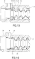
- Figure 16 illustrates an exemplary embodiment of a compression ring 70 sealing a catheter hub assembly having a side port 36.
- a septum 20 having a mounting surface 26 is used to seal the side port 36 as similarly described in the above embodiments.
- the compression ring 70 is used to improve sealing under high fluid pressure from the side port 36 in a similar manner as described in the embodiment of Figure 15 .
- the compression ring 70 is disposed adjacent to the side port 36.
- the compression ring 70 seals the septum 20 to the catheter hub 28 through a press fit, for example, in the septum 20.
- the press fit causes an increase in pressure between the septum 20 and the catheter hub 28.
- the increased pressure pinches the septum 20 and reduces the likelihood of a fluid leak path to form where the fluid can flow outside the septum 20 when entering the catheter hub 28. In this manner, the fluid from the side port 36 can enter the septum 20 and be appropriately regulated.
- the features of the exemplary sealing configuration depicted in Figure 16 may be combined with features of the other exemplary embodiments disclosed herein.
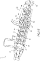
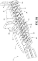
- Figures 17 and 18 illustrate the preferred embodiment of the catheter assembly 10 and the needle safety mechanism 60. This embodiment incorporates the catheter assembly as illustrated in Figures 2 and 3-7 , as well as a needle safety mechanism 60 similarly illustrated in Figure 14 .
- the septum 20 is in the open position.
- the needle 64 is removed.
- the tabs 62 of the needle shield 63 converge and disengage the catheter hub 28.
- the spring 66 axially extends to close the needle safety mechanism 60, provides a distal barrier to the distal tip 68 of the needle 64 and prevents the distal tip 68 from distal re-exposure.
- An outer housing 61 encloses this embodiment of the needle safety mechanism 60.
- the needle safety mechanism 60 does not include the sleeve 65.
- the needle shield 63 remains tapered and includes an exterior stepped surface 67.
- the spring 66 is advantageously released from the exterior stepped surface 67 of the tapered needle shield 63. Accordingly, the spring 66 moves axially beyond the exterior stepped surface 67 and continues to surround the exterior of the needle shield 63. The spring 66 ultimately extends to and contacts the tabs 62 of the needle shield 63.
- Such a configuration radially locks the needle shield 63 into a closed position to prevent the needle 64 from exiting.
- the septum 20 moves to the closed position.
- the bellows 24 applies axial pressure and causes the septum 20 to move into the compression diameter 32.
- the terms “front,” “rear,” “upper,” “lower,” “upwardly,” “downwardly,” and other orientational descriptors are intended to facilitate the description of the exemplary embodiments of the present invention, and are not intended to limit the structure of the exemplary embodiments of the present invention to any particular position or orientation.
- Terms of degree, such as “substantially” or “approximately” are understood by those of ordinary skill to refer to reasonable ranges outside of the given value, for example, general tolerances associated with manufacturing, assembly, and use of the described embodiments.
Description
- This application claims the benefit under 35 U.S.C. § 119(e) of
U.S. Provisional Patent Application Serial No. 62/220,653, filed on September 18, 2015 - Various exemplary embodiments of the invention relate to catheter assemblies.
- Catheter assemblies are used to place a catheter into the vascular system of a patient. Once in place, catheters such as intravenous catheters may be used to infuse fluids including normal saline, medicinal compounds, and/or nutritional compositions into a patient in need of such treatment. Catheters additionally enable the removal of fluids from the circulatory system and monitoring of conditions within the vascular system of the patient.
-
US 2015/202421 A1 describes a ported catheter adapter having a combined blood control valve and port valve, wherein the combined valve comprises one or more vents that permit the passage of air and prevent the passage of fluids. The one or more vents inUS 2015/202421 A1 are located on the outer surface of the valve so as to avoid being overlapped with the pathway of the side port. As such, fluid communication between the side port and the vents is prevented. Various venting configurations are provided inUS 2015/202421 A1 . The device ofUS 2015/202421 A1 further includes a valve actuator that is advanced through a slit in the membrane of the valve to provide a pathway for fluid to bypass the valve. - It is an aspect of the present invention to provide a catheter assembly as defined by claim 1 including a molded-open blood control valve. Generally, septums in the prior art are closed in their natural state and need to be pierced or otherwise engaged to be opened. On the other hand, the septum disclosed herein is open in its natural state and is closed by its housing or an external force, for example. Such a septum provides a plurality of advantages disclosed herein.
- Additionally, the catheter assembly includes a ported catheter where the catheter hub has a side port. The septum disclosed herein is advantageously able to regulate fluid flow from the catheter and the side port simultaneously and independently. Finally, the catheter assembly disclosed herein includes a needle having a reduced diameter that engages the septum during storage to advantageously minimize compression setting.
- The embodiments of the catheter assembly disclosed herein provide advantages of fewer components, improved manufacturing and assembly and more efficient and more reliable operation.
- The foregoing and/or other aspects of the present invention can be achieved by providing a catheter assembly comprising a catheter, a needle having a sharp distal tip disposed within the catheter, and a catheter hub connected to the catheter having the needle passing therethrough, the catheter hub including a valve having a preformed opening that selectively permits or blocks a flow of fluid through the catheter, a first inner diameter that closes the valve, and a second inner diameter larger than the first inner diameter, the second inner diameter opening the valve, wherein the valve is in an open position upon compressing the valve into engagement with the second inner diameter of the catheter hub, and the valve is in a closed position upon releasing the valve to engage the first inner diameter of the catheter hub.
- The foregoing and/or other aspects of the present invention can further be achieved by providing a catheter assembly comprising a catheter, a needle having a sharp distal tip disposed within the catheter, a catheter hub connected to the catheter having the needle passing therethrough, the catheter hub including a valve having a preformed opening that selectively permits or blocks a flow of fluid through the catheter, a first inner diameter that closes the valve, and a second inner diameter larger than the first inner diameter, the second inner diameter opening the valve, and a needle shield that houses the needle, wherein the valve is in an open position upon engaging the needle shield to the catheter hub and compressing the valve into the second inner diameter of the catheter hub, and the valve is in a closed position upon disengaging the needle shield from the catheter assembly, thus releasing the valve to engage the first inner diameter of the catheter hub.
- Additional and/or other aspects and advantages of the present invention will be set forth in the description that follows, or will be apparent from the description, or may be learned by practice of the invention.
- The above aspects and features of the present invention will be more apparent from the description for the exemplary embodiments of the present invention taken with reference to the accompanying drawings, in which:
-
Figure 1 illustrates a perspective view of an exemplary catheter assembly; -
Figure 2 illustrates a cross sectional view of a luer engaging a catheter hub of the catheter assembly ofFigure 1 ; -
Figure 3 illustrates a cross sectional view of another exemplary embodiment of a catheter hub assembly in an open position; -
Figure 4 illustrates another cross sectional view of the catheter hub assembly ofFig. 3 in a closed position; -
Figure 5 illustrates a cross sectional view of the catheter assembly where the septum is in a closed position; -
Figure 6 illustrates another cross sectional view of the catheter assembly ofFigure 5 where the septum is in an open position; -
Figure 7 illustrates another cross sectional view of the catheter assembly ofFigure 5 where the septum is in an open position at a luer connector and at a side port; -
Figure 8 illustrates a cross sectional view of another exemplary embodiment of a catheter hub assembly with a needle including a reduced diameter section; -
Figure 9 illustrates a side perspective view of an exemplary embodiment of the septum including axial flow channels; -
Figure 10 illustrates a cross sectional view of an exemplary embodiment of the catheter hub assembly including a side port and a septum; -
Figure 11 illustrates a cross sectional view of an exemplary embodiment of the catheter hub assembly including a side port and tooling equipment used to assemble the septum; -
Figure 12 illustrates a cross sectional view of an exemplary embodiment of a two-piece catheter assembly; -
Figure 13 illustrates a cross sectional view of another exemplary embodiment of a two-piece catheter assembly; -
Figure 14 illustrates a sectional, side view of needle safety mechanism compatible with the catheter hub assembly; -
Figure 15 illustrates a cross sectional view of another exemplary embodiment of a catheter hub assembly including a side port where a septum seals the side port with an O-ring; -
Figure 16 illustrates a cross sectional view of another exemplary embodiment of a catheter hub assembly including a side port where a septum seals the side port with a compression ring; -
Figure 17 illustrates a right, side cross sectional view of an exemplary embodiment of a catheter assembly and a needle safety mechanism; and -
Figure 18 illustrates a left, side cross sectional view of the exemplary embodiment ofFigure 17 of a catheter assembly and a needle safety mechanism. - A
catheter assembly 10, as shown inFigure 1 , includes ahollow introducer needle 12, acatheter hub 14, and aneedle hub 16. Theintroducer needle 12 has a sharpened distal tip 13 and extends through thecatheter hub 14. Aflexible catheter tube 18 extends from the distal end of thecatheter hub 14, with theneedle 12 passing through thecatheter tube 18. Theflexible catheter tube 18 extends through the catheter opening. Initially, theneedle 12 is inserted into a patient's vein. Thecatheter tube 18 is pushed along theneedle 12 and into the vein following theneedle 12. After thecatheter tube 18 is inserted, theneedle 12 is removed from the patient's vein and thecatheter hub 14, leaving thecatheter tube 18 in the patient as theneedle 12 is discarded. -
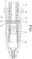
Figure 2 illustrates a cross-sectional view of an exemplary catheter hub assembly. The catheter hub assembly preferably includes ablood control valve 19 that includes aseptum 20 and a compressible section such as abellows 24, for example. Theseptum 20 is positioned in thecatheter hub 28 and functions as a valve that forms a fluid-tight seal and selectively admits fluid to or from theflexible catheter tube 18. In other words, the valve selectively permits or blocks the flow of fluid through theflexible catheter tube 18. - The
septum 20 may be used in any of the embodiments discussed herein. Other septum configurations may be used as would be understood by one of ordinary skill in the art. When thecatheter tube 18 is initially inserted into a patient, and theintroducer needle 12 is removed, theseptum 20 prevents blood from flowing through the channel and out of the distal end. Theseptum 20 is made of an elastic material to form the valve, for example silicone rubber. Other elastic materials may be used and non-elastic materials may be incorporated in theseptum 20 as needed. - The
septum 20 comprises apreformed opening 22 or a molded-open slit. Thepreformed opening 22 of theseptum 20 is preferably formed when theseptum 20 is originally manufactured or in a subsequent machining or cutting operation. Accordingly, when theseptum 20 is in its natural, uncompressed, free or relaxed state, thepreformed opening 22 is open, thus placing theseptum 20 in an open position and acting as an open fluid channel. - On the other hand, when the
septum 20 is radially compressed around thepreformed opening 22, the preformed opening 22 closes and seals to place theseptum 20 in a closed position. Generally, septums in the prior art are closed in their natural state and need to be pierced, deformed or otherwise engaged to be opened. By contrast, theseptum 20 according to this embodiment is open in its natural state and is engaged to be closed. - The
septum 20 includes a bellows 24 that acts as a spring member. The axial spring of thebellows 24 can be simply a tube or can preferably include molded undulations or any other shape that allow thebellows 24 to resiliently compress in a predictable manner and still provide enough spring force for theseptum 20 to operate. The bellows 24 is expanded in its natural state and compressed during operation to allow theseptum 20 to move between the open and closed positions. - The bellows 24 is preferably made of an elastic material, for example silicone rubber. Other elastic materials may be used and non-elastic materials may be incorporated in the
bellows 24 as needed. According to one embodiment, thebellows 24 can be replaced or augmented by a spring member such as a coil spring and used in a catheter hub assembly to cooperate with the preformedopening 22 of theseptum 20. - The
septum 20 further includes a mountingsurface 26. The mountingsurface 26 secures theseptum 20 at a position within the catheter hub assembly. Specifically, the mountingsurface 26 is more rigid compared to the rest of theseptum 20. The mountingsurface 26 also expands in the inner diameter of thecatheter hub 28. Such expansion provides a clamping force to secure theseptum 20 and increased friction to prevent theseptum 20 from being displaced. The bellows 24 is disposed between the mountingsurface 26 and the preformedopening 22. Thus, after securing the mountingsurface 26 of theseptum 20, theseptum 20 can operate between the relaxed and compressed positions. - As illustrated in
Figure 2 , a distal end of thecatheter hub 28 includes a catheter opening and a proximal end includes a Luer connector opening. The inner surface at the proximal end of thecatheter hub 28 surrounds a channel that permits fluid passage through thecatheter hub 28. The outer surface of thecatheter hub 28 includes one or more projections to secure aLuer connector 34 to thecatheter hub 28. The projections may form a threaded connection with theLuer connector 34 or they may connect to theLuer connector 34 through a snap fit or other twisting connection. - One example of a standard connection is a LUER-LOK® connection. Certain types of
Luer connectors 34 utilize a slip fit into thecatheter hub 28. Preferably, theLuer connector 34 travels a significant distance into thecatheter hub 28 prior to contacting theseptum 20. The extended inner diameter at the proximal end of thecatheter hub 28 advantageously allows theLuer connector 34 to be centered in the catheter assembly. Thecatheter hub 28 may be made from a polymer material that is transparent or semi-transparent so that fluid flow through the catheter hub may be observed by a user or it may be made from an opaque material. - The
catheter hub 28 includes various inner diameters that interact with theseptum 20 to provide effective operation. Thecatheter hub 28 includes afree diameter 30 and acompression diameter 32. Thefree diameter 30 is larger than thecompression diameter 32. Thefree diameter 30 is preferably connected to thecompression diameter 32 by a chamferedsurface 31. When a surface surrounding the preformedopening 22 of theseptum 20 is disposed in thefree diameter 30, theseptum 20 is in an open position where fluid is capable of flowing through the preformedopening 22. On the other hand, when the surface surrounding the preformedopening 22 of theseptum 20 is disposed in thecompression diameter 32 and/or in the chamferedsurface 31, theseptum 20 is radially compressed causing the preformedopening 22 to close and seal. This places theseptum 20 in a closed position where fluid is not able to flow through the preformedopening 22. - The
septum 20 is moved from the closed position to the open position by theLuer connector 34, for example. In operation, theLuer connector 34 is supported and centered by the inner diameter at the distal end of the catheter hub prior to interacting with theseptum 20. When theLuer connector 34 initially contacts theseptum 20, the surface surrounding the preformedopening 22 of theseptum 20 is disposed in thecompression diameter 32 and/or the chamferedsurface 31 of thecatheter hub 28. In this position, theseptum 20 is in the closed position where the preformedopening 22 is closed and sealed. - To open the septum 20 (open position), a user can push the
Luer connector 34 into thecatheter hub 28, which pushes the surface surrounding the preformedopening 22 of theseptum 20 into afree diameter 30 of thecatheter hub 28 while axially compressing thebellows 24. In this position, theseptum 20 expands radially, causing the preformedopening 22 to open and allowing a path for fluid to flow. At the same time, theseptum 20 is compressed axially at thebellows 24 to create an increased reacting axial force. - Subsequently, when the user removes the
Luer connector 34 from thecatheter hub 28, thebellows 24 of theseptum 20 expands and causes the surface surrounding the preformedopening 22 of theseptum 20 to enter into the chamferedsurface 31 and/or thecompression diameter 32 of thecatheter hub 28 and enter into the closed position. In the closed position of thecatheter hub 28, thebellows 24 preferably continues to be partially axially compressed to create a force so that theseptum 20 establishes a sealing surface with thefree diameter 30, the chamferedsurface 31 and thecompression diameter 32. - In addition, the
septum 20 does not only operate between a fully relaxed position and a fully compressed position. Theseptum 20 can also operate between a less compressed position and more compressed position. Theseptum 20 can be open when less (partially) compressed and closed when more compressed. Similarly, theseptum 20 can operate in a less relaxed position and a more relaxed position. Theseptum 20 can be open when more relaxed and closed when less (partially) relaxed. Such versatility can be useful in a variety of pressure gradients experienced by theseptum 20. The features of the exemplary septum depicted inFigure 2 may be combined with features of the other exemplary embodiments disclosed herein. -
Figures 3 and 4 illustrate aseptum 40 in a catheter hub assembly according to another exemplary embodiment.Figure 3 depicts theseptum 40 in an open position andFigure 4 depicts theseptum 40 in a closed position. Specifically, the catheter hub assembly includes a two-piece catheter hub including a firstcatheter hub portion 44 and a secondcatheter hub portion 46. A two-piece construction advantageously provides improved assembly and reduced manufacturing cost. The secondcatheter hub portion 46 also includes an undercutsurface 48 that acts as a stopping surface for assembly and operation of theseptum 40. - The
septum 40 includes a sealingsurface 41 that interfaces with aninner diameter 45 and a chamferedsurface 47 of the firstcatheter hub portion 44. The sealingsurface 41 is disposed between thebellows 24 and the preformedopening 22. The sealingsurface 41 of theseptum 40 includes a plurality of throughholes 42 spaced along its perimeter. A variety of shapes, sizes and spacing of the plurality of throughholes 42 is contemplated. On a proximal end of theseptum 40 includes aboss 43 that mates with aLuer connector 34, for example. Theboss 43 andLuer connector 34 interface aids in operation of theseptum 40. Theseptum 40 also includesbellows 24 for proper operation of theseptum 40 as further described below. - When the catheter hub assembly is in the closed state, as illustrated in
Figure 4 , thebellows 24 of theseptum 40 creates a force from the undercutsurface 48 of the secondcatheter hub portion 46 and travels through theseptum 40 to the chamferedsurface 47 and theinner diameter 45 of the firstcatheter hub portion 44. This force causes the sealingsurface 41 of theseptum 40 engage theinner diameter 45 and the chamferedsurface 47 of the firstcatheter hub portion 44. As a result, no fluid can pass through theseptum 40. - The
boss 43 of theseptum 40 centers theLuer connector 34 upon engagement. When theLuer connector 34 engages theboss 43 of theseptum 40 and applies axial pressure sufficient to overcome the pressure exerted by thebellows 24, theseptum 40 moves away from theinner diameter 45 and the chamferedsurface 47 of the firstcatheter hub portion 44. Thus, theseptum 40 enters into an open position as illustrated inFigure 3 . When theseptum 40 opens, the fluid travels between the sealingsurface 41 and the firstcatheter hub portion 44. Next, the fluid travels through the plurality of throughholes 42 and enters into the catheter hub assembly. Upon release of the axial pressure from theLuer connector 34, the pressure in thebellows 24 forces theseptum 40 to return to the closed position as illustrated inFigure 4 and prevents fluid from entering the catheter hub assembly. The features of the exemplary septum depicted inFigures 3 and 4 may be combined with features of the other exemplary embodiments disclosed herein. -
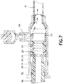
Figures 5-7 illustrate a preferred embodiment of the catheter hub assembly ofFigure 2 and further include aside port 36. The catheter hub assembly of this embodiment operates in a similar manner as described inFigure 2 . However, the mountingsurface 26 of theseptum 20 also selectively permits or blocks a flow of fluid entering through theside port 36. The selective opening and closing of theseptum 20 at the preformedopening 22 and at the mountingsurface 26 operate independently from each other. - The mounting
surface 26 seals theside port 36 via its rigidity and its applied sealing force due to the radial expansion as described in the embodiments above. As illustrated inFigure 7 , to allow for the selective opening of theseptum 20 at the mountingsurface 26, the mountingsurface 26 has a variable thickness across the length of its surface. Preferably, the mountingsurface 26 decreases in thickness while approaching the distal end of theseptum 20. In this manner, the flexibility and stiffness of the mountingsurface 26 is adjusted for effective operation as described below. - In operation, when the fluid force from the
side port 36 overcomes the counteracting forces of the mounting surface 26 (through the material stiffness), theseptum 20 at the mountingsurface 26 will flex and open (seeFigure 7 ) to allow fluid to enter the catheter hub 28 (open position). When the fluid force from theside port 36 is less than the counteracting forces of the mounting surface 26 (through the material stiffness), theseptum 20 at the mountingsurface 26 will close (seeFigures 5 and6 ) and return to its initial state (closed position). Thus, theseptum 20 is advantageously able to regulate fluid flow from the catheter and the side port simultaneously, yet independently. - The
septum 20 can allow fluid to enter thecatheter hub 28 via theLuer connector 34 and theside port 36 in a variety of different operational modes. For example, as illustrated inFigure 6 , the preformedopening 22 can be in the open position while the mountingsurface 26 can be in the closed position. In another operational mode, as illustrated inFigure 7 , the preformedopening 22 and the mountingsurface 26 can both be in the open position. Additionally, the preformedopening 22 can be in the closed position while the mountingsurface 26 can be in the open position. Finally, as illustrated inFigure 5 , the preformedopening 22 and the mountingsurface 26 can both be in the closed position. The features of the exemplary septum depicted inFigures 5-7 may be combined with features of the other exemplary embodiments disclosed herein. -
Figure 8 illustrates an exemplary embodiment of a catheter hub assembly with aneedle 38 having a reduceddiameter 39. During storage of the catheter assembly, it may not be desirable to dispose theseptum 20 in the closed position because the elasticity of theseptum 20 may be compromised over the extended period of time. In other words, if theseptum 20 is disposed in thecompression diameter 32 of thecatheter hub 28 for an extended period of time, theseptum 20 may enter into a compression set and begin to lose the ability to effectively transition between the opened and closed positions. If theseptum 20 enters into a compression set, the sealing strength over the life of theseptum 20 will be compromised. - To address the potential problem described above, according to one embodiment the
septum 20 is disposed in thefree diameter 30 of thecatheter hub 28 and placed in the open position. Meanwhile, theneedle 38 is disposed inside the catheter assembly and the reduceddiameter 39 of theneedle 38 is positioned at thefree diameter 30 of thecatheter hub 28 where the preformedopening 22 of theseptum 20 is located. This open position is maintained during storage. Thus, the catheter assembly can be in storage for long periods of time while applying minimal stress to the preformedopening 22 of theseptum 20. - When the catheter assembly is ready for use, the
needle 38 can aid in the placement of theflexible catheter tube 18 into the patient. Subsequently, theneedle 38 is removed and the catheter assembly can operate in a similar manner described in the above embodiments. Accordingly, the reduceddiameter 39 in theneedle 38 will not have an effect on the flow of fluid or general operation of the catheter assembly. The features of the exemplary needle depicted inFigure 8 may be combined with features of the other exemplary embodiments disclosed herein. - As illustrated in
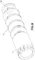
Figure 9 , a plurality ofaxial flow channels 54 can be disposed on a distal end of theseptum 50 while the preformedopening 52 is disposed on the proximal end of theseptum 50. Theflow channels 54 are disposed on an outer circumference of theseptum 50. Fiveflow channels 54 are illustrated, although various quantities and positions are contemplated. Theflow channels 54 have an appropriate width and depth so that when theseptum 50 is not opened, blood can enter into theseptum 50 and air can escape the space distal of theseptum 50 in the front portion of thecatheter hub 28. At the same time, theflow channels 54 are sized small enough to prevent the blood from exiting past the septum 50 (at least for some period of time). Such a configuration is possible because the intermolecular forces in the blood are greater than the intermolecular forces in air. The features of the exemplary septum depicted inFigure 9 may be combined with features of the other exemplary embodiments disclosed herein. -
Figures 10 and 11 illustrate a cross sectional view of a two-piece catheter hub assembly with aside port 36. The catheter hub assembly includes a firstcatheter hub portion 44 and a secondcatheter hub portion 46. The firstcatheter hub portion 44 includes theside port 36. A centerline of theside port 36 is preferably positioned at an angle less than 90 degrees with respect to a centerline of the catheter hub assembly. More preferably, the centerline of theside port 36 is angled at 45 degrees with respect to the centerline of the catheter hub assembly. - The
side port 36 is disposed near the distal end of the firstcatheter hub portion 44. The secondcatheter hub portion 46 includes an undercutsurface 48 that contacts with the distal end of the firstcatheter hub portion 44. When the first and secondcatheter hub portions side port 36 as described above provides enough clearance for the welding process to take place. - After the catheter hub assembly is welded together,
tooling equipment 56 is used to aid in assembling theseptum 20 to the catheter hub assembly. Specifically, as illustrated inFigure 11 , thetooling equipment 56 is secured to theseptum 20 via anotch 51 at the distal end of theseptum 20. Thetooling equipment 56 subsequently pulls theseptum 20 into the catheter hub assembly until theseptum 20 contacts the undercutsurface 48 of the secondcatheter hub portion 46, as illustrated inFigure 10 . Afterward, thetooling equipment 56 is removed and the catheter hub assembly operates in a similar manner as described in the embodiments above. Accordingly, theseptum 20 is capable of sealing the catheter hub assembly at the proximal end and at theside port 36. The features of the exemplary catheter hub assembly method depicted inFigures 10 and 11 may be combined with features of the other exemplary embodiments disclosed herein. -
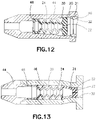
Figure 12 illustrates an alternate embodiment of a two-piece catheter hub assembly. The two piece catheter hub assembly includes a firstcatheter hub portion 44 and a secondcatheter hub portion 46. The firstcatheter hub portion 44 includes afree diameter 30 and an undercutsurface 48 while the secondcatheter hub portion 46 includes acompression diameter 32 and a chamferedsurface 31. - After the
valve 19 is assembled into the firstcatheter hub portion 44 and contacts the undercutsurface 48, the secondcatheter hub portion 46 is fixedly mounted to the inner diameter of the firstcatheter hub portion 44 via a press fit, for example. Accordingly, theseptum 20 having a preformedopening 22 and bellows 24 are able to move from thefree diameter 30 of the firstcatheter hub portion 44 to the chamferedsurface 31 and thecompression diameter 32 of the secondcatheter hub portion 46 to achieve the open and closed positions in a similar manner as described in the embodiments above. The features of the exemplary catheter hub assembly depicted inFigure 12 may be combined with features of the other exemplary embodiments disclosed herein. -
Figure 13 illustrates an alternate embodiment of a two-piece catheter hub assembly. The catheter hub assembly includes a firstcatheter hub portion 44 and a secondcatheter hub portion 46. The firstcatheter hub portion 44 includes a nose sized to receive a specific needle gage. It is contemplated that the nose of the firstcatheter hub portion 44 can be sized for various needle gages. The firstcatheter hub portion 44 also includes an undercutsurface 48 to interact with aseptum 20 as further described below. The secondcatheter hub portion 46 includes afree diameter 30 that is necked down via a chamferedsurface 31 to acompression diameter 32. - The catheter hub assembly is assembled by first placing a
valve 19 into the secondcatheter hub portion 46. A preformedopening 22 of theseptum 20 is disposed in thecompression diameter 32 of the secondcatheter hub portion 46. Subsequently, the firstcatheter hub portion 44 is inserted into the distal end of the secondcatheter hub portion 46 and fixed by a weld joint, for example. Accordingly, bellows 24 in theseptum 20 allows theseptum 20 to contact the undercutsurface 48 of the firstcatheter hub portion 44 and operate in a similar manner as described in the embodiments above. The features of the exemplary catheter hub assembly depicted inFigure 13 may be combined with features of the other exemplary embodiments disclosed herein. -
Figure 14 illustrates an exemplaryneedle safety mechanism 60 that is compatible with the catheter assembly disclosed in the embodiments herein. Theneedle safety mechanism 60 includes aneedle 64 having adeformation 69 located near adistal tip 68 of theneedle 64. Theneedle 64 is used to enter into a patient's vein. Theneedle safety mechanism 60 also includes aneedle shield 63 havingtabs 62 that act as an interlock to engage a catheter hub. Asleeve 65 andspring 66 are disposed in theneedle safety mechanism 60 to apply a radial force from the sleeve and axial movement from thespring 66 upon disengagement. The operation of thesafety mechanism 60 is described as follows. - The catheter assembly is engaged to the
needle safety mechanism 60 while theneedle 64 protrudes through the catheter hub as illustrated inFigure 1 . Specifically, thetabs 62 in theneedle safety mechanism 60 are engaged to a protrusion in an inner diameter of the catheter hub to prevent theneedle safety mechanism 60 from being improperly removed (seeFigures 17 and18 ). - When the catheter tube is placed into the vein of the patient and the user removes the needle from the catheter hub, the
tabs 62 in theneedle safety mechanism 60 will converge. Upon movement of thetabs 62, thespring 66 releases and applies axial pressure to thesleeve 65 and causes theneedle safety mechanism 60 to separate from the catheter hub. As thesleeve 65 moves axially along theneedle shield 63, thesleeve 65 applies a radial force to theneedle shield 63, causing it to close. Subsequently, thesleeve 65 and thespring 66 extend over theneedle shield 63 of theneedle safety mechanism 60 and also secure theneedle 64 in theneedle shield 63 of theneedle safety mechanism 60. Accordingly, theneedle 64 cannot be accidentally removed from theneedle shield 63 of theneedle safety mechanism 60 unless thespring 66 is drawn back. - As the user pulls the
needle 64 out of theneedle safety mechanism 60, theneedle deformation 69 will contact aninterior end wall 71 of theneedle safety mechanism 60. Thus, the user can pull theneedle 64 to pull and remove theneedle safety mechanism 60 from the catheter hub of the catheter assembly. Also, theneedle deformation 69 and theinterior end wall 71 prevent theneedle 64 from separating from theneedle shield 63. - The features of the exemplary needle safety mechanism depicted in
Figure 14 may be combined with features of the other exemplary embodiments disclosed herein. Additionally, a variety of different types of needle safety mechanism can be compatible with the catheter assembly disclosed herein. -
Figure 15 illustrates an exemplary embodiment of an O-ring 58 sealing a catheter hub assembly having aside port 36. Specifically, aseptum 50 having a mountingsurface 26 is used to seal theside port 36. The operation of theseptum 50 with theside port 36 under high fluid pressure is similarly described in the embodiments above. - In the case that high fluid pressure is supplied through the
side port 36, the mountingsurface 26 flexes and allows fluid to enter theseptum 50. The flexing of the mountingsurface 26 may unintentionally create a fluid leak path. Thus, the O-ring 58 is disposed adjacent to theside port 36 and between theseptum 50 and the catheter hub. The O-ring 58 strengthens the sealing surface between theseptum 50 and thecatheter hub 28 and ensures that fluid does not flow outside theseptum 50 when entering thecatheter hub 28. In this manner, the fluid entering from theside port 36 can enter theseptum 50 and be appropriately regulated. The features of the exemplary sealing configuration depicted inFigure 15 may be combined with features of the other exemplary embodiments disclosed herein. -
Figure 16 illustrates an exemplary embodiment of acompression ring 70 sealing a catheter hub assembly having aside port 36. Specifically, aseptum 20 having a mountingsurface 26 is used to seal theside port 36 as similarly described in the above embodiments. Thecompression ring 70 is used to improve sealing under high fluid pressure from theside port 36 in a similar manner as described in the embodiment ofFigure 15 . - The
compression ring 70 is disposed adjacent to theside port 36. Thecompression ring 70 seals theseptum 20 to thecatheter hub 28 through a press fit, for example, in theseptum 20. The press fit causes an increase in pressure between theseptum 20 and thecatheter hub 28. The increased pressure pinches theseptum 20 and reduces the likelihood of a fluid leak path to form where the fluid can flow outside theseptum 20 when entering thecatheter hub 28. In this manner, the fluid from theside port 36 can enter theseptum 20 and be appropriately regulated. The features of the exemplary sealing configuration depicted inFigure 16 may be combined with features of the other exemplary embodiments disclosed herein. -
Figures 17 and18 illustrate the preferred embodiment of thecatheter assembly 10 and theneedle safety mechanism 60. This embodiment incorporates the catheter assembly as illustrated inFigures 2 and3-7 , as well as aneedle safety mechanism 60 similarly illustrated inFigure 14 . - Specifically, when the
needle safety mechanism 60 is engaged to thecatheter assembly 10, theseptum 20 is in the open position. After the catheter tube is set into the vein of the patient, theneedle 64 is removed. After theneedle 64 is removed from thecatheter hub 28 and thedistal tip 68 of theneedle 64 enters into theneedle shield 63, thetabs 62 of theneedle shield 63 converge and disengage thecatheter hub 28. As thetabs 62 converge, thespring 66 axially extends to close theneedle safety mechanism 60, provides a distal barrier to thedistal tip 68 of theneedle 64 and prevents thedistal tip 68 from distal re-exposure. - An
outer housing 61 encloses this embodiment of theneedle safety mechanism 60. However, theneedle safety mechanism 60 does not include thesleeve 65. Instead, theneedle shield 63 remains tapered and includes an exterior steppedsurface 67. When thetabs 62 of theneedle shield 63 disengage thecatheter hub 28, thespring 66 is advantageously released from the exterior steppedsurface 67 of the taperedneedle shield 63. Accordingly, thespring 66 moves axially beyond the exterior steppedsurface 67 and continues to surround the exterior of theneedle shield 63. Thespring 66 ultimately extends to and contacts thetabs 62 of theneedle shield 63. Such a configuration radially locks theneedle shield 63 into a closed position to prevent theneedle 64 from exiting. - When the
needle safety mechanism 60 and thecatheter hub 28 disengage, theseptum 20 moves to the closed position. Specifically, thebellows 24 applies axial pressure and causes theseptum 20 to move into thecompression diameter 32. The features of the exemplary catheter assembly and the needle safety mechanism depicted inFigures 17 and18 may be combined with features of the other exemplary embodiments disclosed herein. - The foregoing detailed description of the certain exemplary embodiments has been provided for the purpose of explaining the principles of the invention and its practical application, thereby enabling others skilled in the art to understand the invention for various embodiments and with various modifications as are suited to the particular use contemplated. This description is not necessarily intended to be exhaustive or to limit the invention to the precise embodiments disclosed. Any of the embodiments and/or elements disclosed herein may be combined with one another to form various additional embodiments not specifically disclosed. Accordingly, additional embodiments are possible and are intended to be encompassed within this specification and the scope of the invention. The specification describes specific examples to accomplish a more general goal that may be accomplished in another way.
- As used in this application, the terms "front," "rear," "upper," "lower," "upwardly," "downwardly," and other orientational descriptors are intended to facilitate the description of the exemplary embodiments of the present invention, and are not intended to limit the structure of the exemplary embodiments of the present invention to any particular position or orientation. Terms of degree, such as "substantially" or "approximately" are understood by those of ordinary skill to refer to reasonable ranges outside of the given value, for example, general tolerances associated with manufacturing, assembly, and use of the described embodiments.
Claims (12)
- A catheter assembly (10) comprising:a catheter;a needle (12) having a sharp distal tip (13); anda catheter hub (14) connected to the catheter having the needle (12) passing therethrough, the catheter hub (14) including:a valve (19) having a preformed opening (22) that selectively permits orblocks a flow of fluid through the catheter;a first inner diameter (32) that closes the valve (19); anda second inner diameter (30) larger than the first inner diameter (32), thesecond inner diameter (30) opening the valve (19);characterized in thatthe valve (19) is in an open position upon axially compressing the valve (19) into engagement with the second inner diameter (30) of the catheter hub (14); andthe valve (19) is in a closed position upon releasing the valve (19) to engage the first inner diameter (32) of the catheter hub (14).
- The catheter assembly (10) of claim 1, wherein the preformed opening (22) comprises a molded-open slit.
- The catheter assembly (10) of claim 1, wherein:the valve (19) includes a bellows (24) that moves the valve (19) from the open position to the closed position;the valve (19) includes a plurality of preformed holes; andthe plurality of preformed holes is disposed between the bellows (24) and the preformed opening (22).
- The catheter assembly (10) of claim 1, wherein the catheter hub (14) further includes a side port (36).
- The catheter assembly (10) of claim 4, wherein an angle between a centerline of the side port (36) and a centerline of the catheter hub (14) is less than 90 degrees.
- The catheter assembly (10) of claim 4, wherein the valve (19) engages the side port (36) to selectively permit or block a flow of fluid through the side port (36).
- The catheter assembly (10) of claim 4, wherein the valve (19) selectively permits or blocks a flow of fluid from the catheter and the side port (36) independently.
- The catheter assembly (10) of claim 1, wherein the valve (19) includes a plurality of axial flow channels (54).
- The catheter assembly (10) of claim 1, further comprising a compression ring (70) that compresses the valve (19) to the catheter hub (14) to prevent a flow of fluid from leaking out of the catheter hub (14).
- The catheter assembly (10) of claim 1, further comprising an O-ring (58) that seals the valve (19) to the catheter hub (14) to prevent a flow of fluid from leaking out of the catheter hub (14).
- The catheter assembly (10) of claim 1, wherein a portion of an inner diameter at a proximal end of the catheter hub (14) does not contact the valve (19) to allow a connector (34) to be centered in the catheter assembly (10) upon engagement with the valve (19).
- The catheter assembly (10) of claim 1, wherein:the needle (12) includes a reduced diameter (39); andthe reduced diameter (39) of the needle engages the preformed opening of the valve (19) during storage to minimize compression setting of the valve (19).
Priority Applications (1)
| Application Number | Priority Date | Filing Date | Title |
|---|---|---|---|
| EP22192612.4A EP4112113A1 (en) | 2015-09-18 | 2016-09-16 | Safety iv catheter with molded-open blood control valve |
Applications Claiming Priority (2)
| Application Number | Priority Date | Filing Date | Title |
|---|---|---|---|
| US201562220653P | 2015-09-18 | 2015-09-18 | |
| PCT/US2016/052232 WO2017049150A1 (en) | 2015-09-18 | 2016-09-16 | Safety iv catheter with molded-open blood control valve |
Related Child Applications (1)
| Application Number | Title | Priority Date | Filing Date |
|---|---|---|---|
| EP22192612.4A Division EP4112113A1 (en) | 2015-09-18 | 2016-09-16 | Safety iv catheter with molded-open blood control valve |
Publications (3)
| Publication Number | Publication Date |
|---|---|
| EP3349840A1 EP3349840A1 (en) | 2018-07-25 |
| EP3349840A4 EP3349840A4 (en) | 2019-10-16 |
| EP3349840B1 true EP3349840B1 (en) | 2022-08-31 |
Family
ID=58289613
Family Applications (2)
| Application Number | Title | Priority Date | Filing Date |
|---|---|---|---|
| EP22192612.4A Pending EP4112113A1 (en) | 2015-09-18 | 2016-09-16 | Safety iv catheter with molded-open blood control valve |
| EP16847438.5A Active EP3349840B1 (en) | 2015-09-18 | 2016-09-16 | Safety iv catheter with molded-open blood control valve |
Family Applications Before (1)
| Application Number | Title | Priority Date | Filing Date |
|---|---|---|---|
| EP22192612.4A Pending EP4112113A1 (en) | 2015-09-18 | 2016-09-16 | Safety iv catheter with molded-open blood control valve |
Country Status (11)
| Country | Link |
|---|---|
| US (1) | US10695551B2 (en) |
| EP (2) | EP4112113A1 (en) |
| JP (2) | JP7117997B2 (en) |
| CN (1) | CN108025166B (en) |
| AU (1) | AU2016323969B2 (en) |
| BR (1) | BR112018005242B1 (en) |
| CA (1) | CA2998359C (en) |
| ES (1) | ES2927498T3 (en) |
| MX (1) | MX2018002918A (en) |
| NZ (1) | NZ740854A (en) |
| WO (1) | WO2017049150A1 (en) |
Families Citing this family (6)
| Publication number | Priority date | Publication date | Assignee | Title |
|---|---|---|---|---|
| JP6970668B2 (en) * | 2015-10-28 | 2021-11-24 | ケアフュージョン 303、インコーポレイテッド | Closed IV access device with Y-port needle free connector |
| US20200222681A1 (en) * | 2019-01-14 | 2020-07-16 | Becton, Dickinson And Company | Needleless access connector facilitating instrument delivery to a catheter assembly |
| US11660253B2 (en) * | 2019-09-18 | 2023-05-30 | Medisarang Co., Ltd. | Device for extracting platelet rich plasma |
| US11464943B2 (en) | 2019-11-12 | 2022-10-11 | Becton, Dickinson And Company | Assisted catheter advancement |
| US20210299429A1 (en) * | 2020-03-31 | 2021-09-30 | Becton, Dickinson And Company | Catheter assembly with a slidable septum and related systems and methods |
| KR20240012402A (en) * | 2021-05-27 | 2024-01-29 | 백톤 디킨슨 앤드 컴퍼니 | Retainer element for securing catheter adapter valves |
Family Cites Families (21)
| Publication number | Priority date | Publication date | Assignee | Title |
|---|---|---|---|---|
| US5549651A (en) | 1994-05-25 | 1996-08-27 | Lynn; Lawrence A. | Luer-receiving medical valve and fluid transfer method |
| US5470319A (en) * | 1994-06-20 | 1995-11-28 | Critical Device Corporation | Needleless injection site |
| NZ286445A (en) * | 1995-05-16 | 1997-12-19 | Ivac Corp | Needleless luer connector: deformable piston occludes bore |
| US5814024A (en) * | 1996-11-27 | 1998-09-29 | Elcam Plastics | Needleless valve |
| US5967490A (en) | 1997-01-08 | 1999-10-19 | Vadus, Inc. | Catheter hubs having a valve |
| JP4996015B2 (en) * | 2001-03-12 | 2012-08-08 | メディキット株式会社 | Indwelling catheter |
| US6663592B2 (en) | 2001-09-06 | 2003-12-16 | Medex, Inc. | Catheter introducer assembly having safety shielded needle |
| EP1886710B1 (en) | 2002-06-20 | 2016-12-14 | Becton, Dickinson and Company | Catheter and introducer needle assembly with needle shield |
| US7125396B2 (en) | 2002-12-30 | 2006-10-24 | Cardinal Health 303, Inc. | Safety catheter system and method |
| US7585288B2 (en) * | 2004-01-23 | 2009-09-08 | Genico, Inc. | Trocar and cannula assembly having conical valve and related methods |
| US7918863B2 (en) * | 2005-06-24 | 2011-04-05 | Conceptus, Inc. | Minimally invasive surgical stabilization devices and methods |
| US8343104B2 (en) | 2007-06-29 | 2013-01-01 | Medical Components, Inc. | Closable and openable catheter assembly and method of using same |
| US8679090B2 (en) * | 2008-12-19 | 2014-03-25 | Icu Medical, Inc. | Medical connector with closeable luer connector |
| EP2517751B8 (en) | 2011-04-27 | 2018-02-28 | Kpr U.S., Llc | Safety IV catheter assemblies |
| US8622967B2 (en) * | 2012-05-15 | 2014-01-07 | Becton, Dickinson And Company | Over-the-needle intravenous catheter assembly with integrated intravenous tubing |
| EP2916905A4 (en) * | 2012-11-12 | 2016-11-09 | Icu Medical Inc | Medical connector |
| CN203724591U (en) * | 2013-03-15 | 2014-07-23 | B.布劳恩梅尔松根股份公司 | Valve control duct assembly |
| US9114231B2 (en) * | 2013-03-15 | 2015-08-25 | B. Braun Melsungen Ag | Valved catheter assemblies and related methods |
| US8979802B2 (en) * | 2013-03-15 | 2015-03-17 | B. Braun Melsungen Ag | Safety IV catheter assembly with seal |
| US9381320B2 (en) | 2013-03-18 | 2016-07-05 | Becton, Dickinson And Company | Multiple-use intravenous catheter assembly septum and septum actuator |
| US9750925B2 (en) | 2014-01-21 | 2017-09-05 | Becton, Dickinson And Company | Ported catheter adapter having combined port and blood control valve with venting |
-
2016
- 2016-09-16 NZ NZ740854A patent/NZ740854A/en unknown
- 2016-09-16 WO PCT/US2016/052232 patent/WO2017049150A1/en active Application Filing
- 2016-09-16 BR BR112018005242-6A patent/BR112018005242B1/en active IP Right Grant
- 2016-09-16 EP EP22192612.4A patent/EP4112113A1/en active Pending
- 2016-09-16 ES ES16847438T patent/ES2927498T3/en active Active
- 2016-09-16 JP JP2018514302A patent/JP7117997B2/en active Active
- 2016-09-16 CN CN201680053825.7A patent/CN108025166B/en active Active
- 2016-09-16 MX MX2018002918A patent/MX2018002918A/en unknown
- 2016-09-16 EP EP16847438.5A patent/EP3349840B1/en active Active
- 2016-09-16 CA CA2998359A patent/CA2998359C/en active Active
- 2016-09-16 US US15/760,816 patent/US10695551B2/en active Active
- 2016-09-16 AU AU2016323969A patent/AU2016323969B2/en active Active
-
2022
- 2022-05-25 JP JP2022085254A patent/JP2022109322A/en active Pending
Also Published As
| Publication number | Publication date |
|---|---|
| CA2998359C (en) | 2024-02-06 |
| AU2016323969B2 (en) | 2020-12-10 |
| BR112018005242B1 (en) | 2022-05-03 |
| CN108025166B (en) | 2020-11-13 |
| EP3349840A1 (en) | 2018-07-25 |
| EP3349840A4 (en) | 2019-10-16 |
| AU2016323969A1 (en) | 2018-04-12 |
| JP2022109322A (en) | 2022-07-27 |
| MX2018002918A (en) | 2018-06-07 |
| ES2927498T3 (en) | 2022-11-07 |
| CN108025166A (en) | 2018-05-11 |
| CA2998359A1 (en) | 2017-03-23 |
| NZ740854A (en) | 2022-02-25 |
| JP7117997B2 (en) | 2022-08-15 |
| EP4112113A1 (en) | 2023-01-04 |
| BR112018005242A2 (en) | 2018-10-02 |
| WO2017049150A1 (en) | 2017-03-23 |
| US20180256885A1 (en) | 2018-09-13 |
| US10695551B2 (en) | 2020-06-30 |
| JP2018531663A (en) | 2018-11-01 |
Similar Documents
| Publication | Publication Date | Title |
|---|---|---|
| EP3349840B1 (en) | Safety iv catheter with molded-open blood control valve | |
| CN107913461B (en) | Compliant catheter adapter with autogenous cutting needle | |
| US7938805B2 (en) | Radially compressible blood control valve | |
| CN106456958B (en) | Valved conduit apparatus and related methods | |
| EP2550057B1 (en) | New needleless access connector and method of use | |
| EP2806923B1 (en) | Needleless valve system | |
| CN109789291B (en) | Intravenous catheter apparatus with safety function and pressure control valve element | |
| EP3495016A1 (en) | Valved needle assembly, and indwelling needle assembly | |
| US20240009406A1 (en) | Hemostasis valve-equipped indwelling needle and indwelling needle assembly | |
| EP3294396B1 (en) | Catheter devices with seals and related methods | |
| EP3268076A1 (en) | Catheter assemblies with flow control valve mechanisms and related methods | |
| EP3500329A1 (en) | Needle assemblies and related methods |
Legal Events
| Date | Code | Title | Description |
|---|---|---|---|
| STAA | Information on the status of an ep patent application or granted ep patent |
Free format text: STATUS: THE INTERNATIONAL PUBLICATION HAS BEEN MADE |
|
| PUAI | Public reference made under article 153(3) epc to a published international application that has entered the european phase |
Free format text: ORIGINAL CODE: 0009012 |
|
| STAA | Information on the status of an ep patent application or granted ep patent |
Free format text: STATUS: REQUEST FOR EXAMINATION WAS MADE |
|
| 17P | Request for examination filed |
Effective date: 20180312 |
|
| AK | Designated contracting states |
Kind code of ref document: A1 Designated state(s): AL AT BE BG CH CY CZ DE DK EE ES FI FR GB GR HR HU IE IS IT LI LT LU LV MC MK MT NL NO PL PT RO RS SE SI SK SM TR |
|
| AX | Request for extension of the european patent |
Extension state: BA ME |
|
| RIN1 | Information on inventor provided before grant (corrected) |
Inventor name: CLUFF, KEN Inventor name: ISAACSON, RAY Inventor name: BURKHOLZ, JON Inventor name: LIU, HUIBIN Inventor name: TRAINER, LAWRENCE J. Inventor name: SHEVGOOR, SIDDARTH |
|
| DAV | Request for validation of the european patent (deleted) | ||
| DAX | Request for extension of the european patent (deleted) | ||
| RIN1 | Information on inventor provided before grant (corrected) |
Inventor name: ISAACSON, RAY Inventor name: BURKHOLZ, JON Inventor name: SHEVGOOR, SIDDARTH Inventor name: TRAINER, LAWRENCE J. Inventor name: CLUFF, KEN Inventor name: LIU, HUIBIN |
|
| A4 | Supplementary search report drawn up and despatched |
Effective date: 20190912 |
|
| RIC1 | Information provided on ipc code assigned before grant |
Ipc: A61M 39/06 20060101AFI20190906BHEP Ipc: A61M 5/32 20060101ALI20190906BHEP Ipc: A61M 39/24 20060101ALI20190906BHEP Ipc: A61M 39/10 20060101ALI20190906BHEP Ipc: A61M 39/26 20060101ALI20190906BHEP Ipc: A61M 5/00 20060101ALI20190906BHEP Ipc: A61M 5/178 20060101ALI20190906BHEP Ipc: A61M 25/06 20060101ALI20190906BHEP |
|
| GRAP | Despatch of communication of intention to grant a patent |
Free format text: ORIGINAL CODE: EPIDOSNIGR1 |
|
| STAA | Information on the status of an ep patent application or granted ep patent |
Free format text: STATUS: GRANT OF PATENT IS INTENDED |
|
| INTG | Intention to grant announced |
Effective date: 20220324 |
|
| GRAS | Grant fee paid |
Free format text: ORIGINAL CODE: EPIDOSNIGR3 |
|
| GRAA | (expected) grant |
Free format text: ORIGINAL CODE: 0009210 |
|
| STAA | Information on the status of an ep patent application or granted ep patent |
Free format text: STATUS: THE PATENT HAS BEEN GRANTED |
|
| AK | Designated contracting states |
Kind code of ref document: B1 Designated state(s): AL AT BE BG CH CY CZ DE DK EE ES FI FR GB GR HR HU IE IS IT LI LT LU LV MC MK MT NL NO PL PT RO RS SE SI SK SM TR |
|
| REG | Reference to a national code |
Ref country code: CH Ref legal event code: EP Ref country code: GB Ref legal event code: FG4D |
|
| REG | Reference to a national code |
Ref country code: AT Ref legal event code: REF Ref document number: 1514853 Country of ref document: AT Kind code of ref document: T Effective date: 20220915 |
|
| REG | Reference to a national code |
Ref country code: DE Ref legal event code: R096 Ref document number: 602016074720 Country of ref document: DE |
|
| REG | Reference to a national code |
Ref country code: IE Ref legal event code: FG4D |
|
| REG | Reference to a national code |
Ref country code: ES Ref legal event code: FG2A Ref document number: 2927498 Country of ref document: ES Kind code of ref document: T3 Effective date: 20221107 |
|
| REG | Reference to a national code |
Ref country code: LT Ref legal event code: MG9D |
|
| REG | Reference to a national code |
Ref country code: NL Ref legal event code: MP Effective date: 20220831 |
|
| PG25 | Lapsed in a contracting state [announced via postgrant information from national office to epo] |
Ref country code: SE Free format text: LAPSE BECAUSE OF FAILURE TO SUBMIT A TRANSLATION OF THE DESCRIPTION OR TO PAY THE FEE WITHIN THE PRESCRIBED TIME-LIMIT Effective date: 20220831 Ref country code: RS Free format text: LAPSE BECAUSE OF FAILURE TO SUBMIT A TRANSLATION OF THE DESCRIPTION OR TO PAY THE FEE WITHIN THE PRESCRIBED TIME-LIMIT Effective date: 20220831 Ref country code: NO Free format text: LAPSE BECAUSE OF FAILURE TO SUBMIT A TRANSLATION OF THE DESCRIPTION OR TO PAY THE FEE WITHIN THE PRESCRIBED TIME-LIMIT Effective date: 20221130 Ref country code: LV Free format text: LAPSE BECAUSE OF FAILURE TO SUBMIT A TRANSLATION OF THE DESCRIPTION OR TO PAY THE FEE WITHIN THE PRESCRIBED TIME-LIMIT Effective date: 20220831 Ref country code: LT Free format text: LAPSE BECAUSE OF FAILURE TO SUBMIT A TRANSLATION OF THE DESCRIPTION OR TO PAY THE FEE WITHIN THE PRESCRIBED TIME-LIMIT Effective date: 20220831 Ref country code: FI Free format text: LAPSE BECAUSE OF FAILURE TO SUBMIT A TRANSLATION OF THE DESCRIPTION OR TO PAY THE FEE WITHIN THE PRESCRIBED TIME-LIMIT Effective date: 20220831 |
|
| REG | Reference to a national code |
Ref country code: AT Ref legal event code: MK05 Ref document number: 1514853 Country of ref document: AT Kind code of ref document: T Effective date: 20220831 |
|
| PG25 | Lapsed in a contracting state [announced via postgrant information from national office to epo] |
Ref country code: PL Free format text: LAPSE BECAUSE OF FAILURE TO SUBMIT A TRANSLATION OF THE DESCRIPTION OR TO PAY THE FEE WITHIN THE PRESCRIBED TIME-LIMIT Effective date: 20220831 Ref country code: IS Free format text: LAPSE BECAUSE OF FAILURE TO SUBMIT A TRANSLATION OF THE DESCRIPTION OR TO PAY THE FEE WITHIN THE PRESCRIBED TIME-LIMIT Effective date: 20221231 Ref country code: HR Free format text: LAPSE BECAUSE OF FAILURE TO SUBMIT A TRANSLATION OF THE DESCRIPTION OR TO PAY THE FEE WITHIN THE PRESCRIBED TIME-LIMIT Effective date: 20220831 Ref country code: GR Free format text: LAPSE BECAUSE OF FAILURE TO SUBMIT A TRANSLATION OF THE DESCRIPTION OR TO PAY THE FEE WITHIN THE PRESCRIBED TIME-LIMIT Effective date: 20221201 |
|
| PG25 | Lapsed in a contracting state [announced via postgrant information from national office to epo] |
Ref country code: SM Free format text: LAPSE BECAUSE OF FAILURE TO SUBMIT A TRANSLATION OF THE DESCRIPTION OR TO PAY THE FEE WITHIN THE PRESCRIBED TIME-LIMIT Effective date: 20220831 Ref country code: RO Free format text: LAPSE BECAUSE OF FAILURE TO SUBMIT A TRANSLATION OF THE DESCRIPTION OR TO PAY THE FEE WITHIN THE PRESCRIBED TIME-LIMIT Effective date: 20220831 Ref country code: PT Free format text: LAPSE BECAUSE OF FAILURE TO SUBMIT A TRANSLATION OF THE DESCRIPTION OR TO PAY THE FEE WITHIN THE PRESCRIBED TIME-LIMIT Effective date: 20230102 Ref country code: DK Free format text: LAPSE BECAUSE OF FAILURE TO SUBMIT A TRANSLATION OF THE DESCRIPTION OR TO PAY THE FEE WITHIN THE PRESCRIBED TIME-LIMIT Effective date: 20220831 Ref country code: CZ Free format text: LAPSE BECAUSE OF FAILURE TO SUBMIT A TRANSLATION OF THE DESCRIPTION OR TO PAY THE FEE WITHIN THE PRESCRIBED TIME-LIMIT Effective date: 20220831 Ref country code: AT Free format text: LAPSE BECAUSE OF FAILURE TO SUBMIT A TRANSLATION OF THE DESCRIPTION OR TO PAY THE FEE WITHIN THE PRESCRIBED TIME-LIMIT Effective date: 20220831 |
|
| REG | Reference to a national code |
Ref country code: CH Ref legal event code: PL |
|
| PG25 | Lapsed in a contracting state [announced via postgrant information from national office to epo] |
Ref country code: SK Free format text: LAPSE BECAUSE OF FAILURE TO SUBMIT A TRANSLATION OF THE DESCRIPTION OR TO PAY THE FEE WITHIN THE PRESCRIBED TIME-LIMIT Effective date: 20220831 Ref country code: MC Free format text: LAPSE BECAUSE OF FAILURE TO SUBMIT A TRANSLATION OF THE DESCRIPTION OR TO PAY THE FEE WITHIN THE PRESCRIBED TIME-LIMIT Effective date: 20220831 Ref country code: EE Free format text: LAPSE BECAUSE OF FAILURE TO SUBMIT A TRANSLATION OF THE DESCRIPTION OR TO PAY THE FEE WITHIN THE PRESCRIBED TIME-LIMIT Effective date: 20220831 |
|
| REG | Reference to a national code |
Ref country code: DE Ref legal event code: R097 Ref document number: 602016074720 Country of ref document: DE |
|
| PG25 | Lapsed in a contracting state [announced via postgrant information from national office to epo] |
Ref country code: NL Free format text: LAPSE BECAUSE OF FAILURE TO SUBMIT A TRANSLATION OF THE DESCRIPTION OR TO PAY THE FEE WITHIN THE PRESCRIBED TIME-LIMIT Effective date: 20220831 Ref country code: LU Free format text: LAPSE BECAUSE OF NON-PAYMENT OF DUE FEES Effective date: 20220916 Ref country code: AL Free format text: LAPSE BECAUSE OF FAILURE TO SUBMIT A TRANSLATION OF THE DESCRIPTION OR TO PAY THE FEE WITHIN THE PRESCRIBED TIME-LIMIT Effective date: 20220831 |
|
| PLBE | No opposition filed within time limit |
Free format text: ORIGINAL CODE: 0009261 |
|
| STAA | Information on the status of an ep patent application or granted ep patent |
Free format text: STATUS: NO OPPOSITION FILED WITHIN TIME LIMIT |
|
| PG25 | Lapsed in a contracting state [announced via postgrant information from national office to epo] |
Ref country code: LI Free format text: LAPSE BECAUSE OF NON-PAYMENT OF DUE FEES Effective date: 20220930 Ref country code: IE Free format text: LAPSE BECAUSE OF NON-PAYMENT OF DUE FEES Effective date: 20220916 Ref country code: CH Free format text: LAPSE BECAUSE OF NON-PAYMENT OF DUE FEES Effective date: 20220930 |
|
| 26N | No opposition filed |
Effective date: 20230601 |
|
| PG25 | Lapsed in a contracting state [announced via postgrant information from national office to epo] |
Ref country code: SI Free format text: LAPSE BECAUSE OF FAILURE TO SUBMIT A TRANSLATION OF THE DESCRIPTION OR TO PAY THE FEE WITHIN THE PRESCRIBED TIME-LIMIT Effective date: 20220831 |
|
| PGFP | Annual fee paid to national office [announced via postgrant information from national office to epo] |
Ref country code: IT Payment date: 20230822 Year of fee payment: 8 Ref country code: GB Payment date: 20230823 Year of fee payment: 8 |
|
| PGFP | Annual fee paid to national office [announced via postgrant information from national office to epo] |
Ref country code: FR Payment date: 20230822 Year of fee payment: 8 Ref country code: DE Payment date: 20230822 Year of fee payment: 8 Ref country code: BE Payment date: 20230822 Year of fee payment: 8 |
|
| PGFP | Annual fee paid to national office [announced via postgrant information from national office to epo] |
Ref country code: ES Payment date: 20231002 Year of fee payment: 8 |
|
| PG25 | Lapsed in a contracting state [announced via postgrant information from national office to epo] |
Ref country code: HU Free format text: LAPSE BECAUSE OF FAILURE TO SUBMIT A TRANSLATION OF THE DESCRIPTION OR TO PAY THE FEE WITHIN THE PRESCRIBED TIME-LIMIT; INVALID AB INITIO Effective date: 20160916 |