JP2018531663A - Safety IV catheter with molded open blood control valve - Google Patents
Safety IV catheter with molded open blood control valve Download PDFInfo
- Publication number
- JP2018531663A JP2018531663A JP2018514302A JP2018514302A JP2018531663A JP 2018531663 A JP2018531663 A JP 2018531663A JP 2018514302 A JP2018514302 A JP 2018514302A JP 2018514302 A JP2018514302 A JP 2018514302A JP 2018531663 A JP2018531663 A JP 2018531663A
- Authority
- JP
- Japan
- Prior art keywords
- catheter
- valve
- catheter hub
- needle
- septum
- Prior art date
- Legal status (The legal status is an assumption and is not a legal conclusion. Google has not performed a legal analysis and makes no representation as to the accuracy of the status listed.)
- Granted
Links
Images


Classifications
-
- A—HUMAN NECESSITIES
- A61—MEDICAL OR VETERINARY SCIENCE; HYGIENE
- A61M—DEVICES FOR INTRODUCING MEDIA INTO, OR ONTO, THE BODY; DEVICES FOR TRANSDUCING BODY MEDIA OR FOR TAKING MEDIA FROM THE BODY; DEVICES FOR PRODUCING OR ENDING SLEEP OR STUPOR
- A61M39/00—Tubes, tube connectors, tube couplings, valves, access sites or the like, specially adapted for medical use
- A61M39/22—Valves or arrangement of valves
- A61M39/26—Valves closing automatically on disconnecting the line and opening on reconnection thereof
-
- A—HUMAN NECESSITIES
- A61—MEDICAL OR VETERINARY SCIENCE; HYGIENE
- A61M—DEVICES FOR INTRODUCING MEDIA INTO, OR ONTO, THE BODY; DEVICES FOR TRANSDUCING BODY MEDIA OR FOR TAKING MEDIA FROM THE BODY; DEVICES FOR PRODUCING OR ENDING SLEEP OR STUPOR
- A61M25/00—Catheters; Hollow probes
- A61M25/01—Introducing, guiding, advancing, emplacing or holding catheters
- A61M25/06—Body-piercing guide needles or the like
- A61M25/0606—"Over-the-needle" catheter assemblies, e.g. I.V. catheters
-
- A—HUMAN NECESSITIES
- A61—MEDICAL OR VETERINARY SCIENCE; HYGIENE
- A61M—DEVICES FOR INTRODUCING MEDIA INTO, OR ONTO, THE BODY; DEVICES FOR TRANSDUCING BODY MEDIA OR FOR TAKING MEDIA FROM THE BODY; DEVICES FOR PRODUCING OR ENDING SLEEP OR STUPOR
- A61M39/00—Tubes, tube connectors, tube couplings, valves, access sites or the like, specially adapted for medical use
- A61M39/02—Access sites
- A61M39/06—Haemostasis valves, i.e. gaskets sealing around a needle, catheter or the like, closing on removal thereof
- A61M39/0606—Haemostasis valves, i.e. gaskets sealing around a needle, catheter or the like, closing on removal thereof without means for adjusting the seal opening or pressure
-
- A—HUMAN NECESSITIES
- A61—MEDICAL OR VETERINARY SCIENCE; HYGIENE
- A61M—DEVICES FOR INTRODUCING MEDIA INTO, OR ONTO, THE BODY; DEVICES FOR TRANSDUCING BODY MEDIA OR FOR TAKING MEDIA FROM THE BODY; DEVICES FOR PRODUCING OR ENDING SLEEP OR STUPOR
- A61M39/00—Tubes, tube connectors, tube couplings, valves, access sites or the like, specially adapted for medical use
- A61M39/02—Access sites
- A61M39/06—Haemostasis valves, i.e. gaskets sealing around a needle, catheter or the like, closing on removal thereof
- A61M2039/062—Haemostasis valves, i.e. gaskets sealing around a needle, catheter or the like, closing on removal thereof used with a catheter
-
- A—HUMAN NECESSITIES
- A61—MEDICAL OR VETERINARY SCIENCE; HYGIENE
- A61M—DEVICES FOR INTRODUCING MEDIA INTO, OR ONTO, THE BODY; DEVICES FOR TRANSDUCING BODY MEDIA OR FOR TAKING MEDIA FROM THE BODY; DEVICES FOR PRODUCING OR ENDING SLEEP OR STUPOR
- A61M39/00—Tubes, tube connectors, tube couplings, valves, access sites or the like, specially adapted for medical use
- A61M39/02—Access sites
- A61M39/06—Haemostasis valves, i.e. gaskets sealing around a needle, catheter or the like, closing on removal thereof
- A61M2039/0633—Haemostasis valves, i.e. gaskets sealing around a needle, catheter or the like, closing on removal thereof the seal being a passive seal made of a resilient material with or without an opening
- A61M2039/064—Slit-valve
-
- A—HUMAN NECESSITIES
- A61—MEDICAL OR VETERINARY SCIENCE; HYGIENE
- A61M—DEVICES FOR INTRODUCING MEDIA INTO, OR ONTO, THE BODY; DEVICES FOR TRANSDUCING BODY MEDIA OR FOR TAKING MEDIA FROM THE BODY; DEVICES FOR PRODUCING OR ENDING SLEEP OR STUPOR
- A61M39/00—Tubes, tube connectors, tube couplings, valves, access sites or the like, specially adapted for medical use
- A61M39/22—Valves or arrangement of valves
- A61M39/24—Check- or non-return valves
- A61M2039/2433—Valve comprising a resilient or deformable element, e.g. flap valve, deformable disc
-
- A—HUMAN NECESSITIES
- A61—MEDICAL OR VETERINARY SCIENCE; HYGIENE
- A61M—DEVICES FOR INTRODUCING MEDIA INTO, OR ONTO, THE BODY; DEVICES FOR TRANSDUCING BODY MEDIA OR FOR TAKING MEDIA FROM THE BODY; DEVICES FOR PRODUCING OR ENDING SLEEP OR STUPOR
- A61M5/00—Devices for bringing media into the body in a subcutaneous, intra-vascular or intramuscular way; Accessories therefor, e.g. filling or cleaning devices, arm-rests
- A61M5/178—Syringes
- A61M5/31—Details
- A61M5/32—Needles; Details of needles pertaining to their connection with syringe or hub; Accessories for bringing the needle into, or holding the needle on, the body; Devices for protection of needles
- A61M5/3205—Apparatus for removing or disposing of used needles or syringes, e.g. containers; Means for protection against accidental injuries from used needles
- A61M5/321—Means for protection against accidental injuries by used needles
- A61M5/3243—Means for protection against accidental injuries by used needles being axially-extensible, e.g. protective sleeves coaxially slidable on the syringe barrel
- A61M5/3273—Means for protection against accidental injuries by used needles being axially-extensible, e.g. protective sleeves coaxially slidable on the syringe barrel freely sliding on needle shaft without connection to syringe or needle
Landscapes
- Health & Medical Sciences (AREA)
- Heart & Thoracic Surgery (AREA)
- Life Sciences & Earth Sciences (AREA)
- Hematology (AREA)
- Anesthesiology (AREA)
- Biomedical Technology (AREA)
- Engineering & Computer Science (AREA)
- Pulmonology (AREA)
- Animal Behavior & Ethology (AREA)
- General Health & Medical Sciences (AREA)
- Public Health (AREA)
- Veterinary Medicine (AREA)
- Biophysics (AREA)
- Infusion, Injection, And Reservoir Apparatuses (AREA)
- Media Introduction/Drainage Providing Device (AREA)
Abstract
カテーテルアセンブリは、カテーテル(18)と、鋭利な遠位先端部(13)を有するニードル(12)と、ニードル(12)が貫通するカテーテル(18)に接続されたカテーテルハブ(18)を通る流体の流れを選択的に許容または遮断する予め形成された開口(22)を有するバルブ(19)と、バルブ(19)を閉鎖する第1内径部(32)と、第1の内径(32)よりも大きい第2の内径(30)とを有する。バルブ(19)を解放してカテーテルハブ(14)の第1の内径(32)と係合したとたん、バルブ(19)は閉鎖位置にある。The catheter assembly includes a catheter (18), a needle (12) having a sharp distal tip (13), and a fluid passing through a catheter hub (18) connected to the catheter (18) through which the needle (12) passes. A valve (19) having a pre-formed opening (22) for selectively allowing or blocking the flow of the gas, a first inner diameter portion (32) for closing the valve (19), and a first inner diameter (32). And a second inner diameter (30) that is larger. As soon as the valve (19) is released and engaged with the first inner diameter (32) of the catheter hub (14), the valve (19) is in the closed position.
Description
本出願は、2015年9月18日に出願された、35U.S.C.§119(e)による米国仮特許出願第62/220,653号に基づく優先権の利益を主張するものであり、その開示内容全体が参照により本明細書に組み込まれる。 This application was filed on September 18, 2015, 35 U.S. S. C. §119 (e) claims priority benefit under US Provisional Patent Application No. 62 / 220,653, the entire disclosure of which is incorporated herein by reference.
本発明の様々な例示的実施形態は、カテーテルアセンブリに関する。 Various exemplary embodiments of the invention relate to catheter assemblies.
カテーテルアセンブリは、カテーテルを患者の血管系内に配置するために使用される。一旦適所に配置されると、静脈カテーテルなどのカテーテルを使用して、正常な生理食塩水、医薬化合物および/または栄養組成物を含む流体を、処理することができる。カテーテルは、さらに、循環系からの流体の除去および患者の血管系内の状態の監視を可能にする。 The catheter assembly is used to place the catheter in the patient's vasculature. Once in place, a catheter, such as a venous catheter, can be used to treat fluid containing normal saline, pharmaceutical compounds and / or nutritional compositions. The catheter further allows removal of fluid from the circulatory system and monitoring of conditions in the patient's vasculature.
本発明の一態様は、成型された開放型血液制御バルブを含むカテーテルアセンブリを提供することである。一般に、従来技術のセプタムは自然の状態では閉じられており、穿孔されるか、または開かれるように係合される必要がある。一方、本明細書が開示するセプタムは、自然の状態では開いており、例えば、そのハウジングまたは外力によって閉じられている。そのようなセプタムは、本明細書で開示する複数の利点を提供する。 One aspect of the present invention is to provide a catheter assembly that includes a molded open blood control valve. In general, prior art septa are closed in nature and need to be drilled or engaged to be opened. On the other hand, the septum disclosed herein is open in the natural state and is closed, for example, by its housing or external force. Such a septum provides a number of advantages as disclosed herein.
さらに、カテーテルアセンブリは、カテーテルハブがサイドポートを有する、ポート付きカテーテルを含む。本明細書で開示されるセプタムは、有利には、カテーテルおよびサイドポートからの流体の流れを同時にかつ独立して調節することができる。最後に、本明細書で開示されるカテーテルアセンブリは、保存中にセプタムと係合する、直径が縮小されたニードルを含み、圧縮設定を有利に最小にし、信頼性の高い操作が可能であるる。 In addition, the catheter assembly includes a ported catheter where the catheter hub has a side port. The septum disclosed herein can advantageously regulate fluid flow from the catheter and side port simultaneously and independently. Finally, the catheter assembly disclosed herein includes a reduced diameter needle that engages the septum during storage, advantageously minimizing the compression setting and allowing for reliable operation. .
本明細書が開示する実施形態は、より少ないコンポーネント、改良された製造性およびアセンブリ、および、より効率的でより信頼性の高い操作を提供する。 The embodiments disclosed herein provide fewer components, improved manufacturability and assembly, and more efficient and more reliable operation.
本発明の上記および/または他の態様は、カテーテルと、カテーテル内に配置された鋭い先端チップを有するニードルと、カテーテルに接続されたニードルを貫通するカテーテルハブを含むカテーテルアセンブリを提供することによって達成することができる。カテーテルハブは、予め形成された開口を有するバルブであって、カテーテルを通る流体の流れを選択的に許容または遮断するバルブと、バルブを閉鎖する第1の内径と、第1の内径よりも大きい第2の内径であって、バルブを開放する第2の内径を含む。バルブは、バルブを軸方向に圧縮してカテーテルハブの第2の内径と係合したときに、開放位置にあり、バルブは、バルブを解放してカテーテルハブの第1の内径と係合したときに、閉鎖位置にある。 The above and / or other aspects of the present invention are accomplished by providing a catheter assembly including a catheter, a needle having a sharp tip disposed within the catheter, and a catheter hub extending through the needle connected to the catheter. can do. The catheter hub is a valve having a preformed opening that selectively allows or blocks fluid flow through the catheter, a first inner diameter that closes the valve, and is larger than the first inner diameter. A second inner diameter that includes a second inner diameter that opens the valve; The valve is in the open position when the valve is axially compressed to engage the second inner diameter of the catheter hub, and the valve is released to engage the first inner diameter of the catheter hub. In the closed position.
本発明の上記および/または他の態様は、カテーテルと、カテーテル内に配置された鋭い先端チップを有するニードルと、カテーテルに接続されたニードルを貫通するカテーテルハブと、ニードルを収容するニードルシールドを含むカテーテルアセンブリを提供することによって達成することができる。カテーテルハブは、予め形成された開口を有するバルブであって、カテーテルを通る流体の流れを選択的に許容または遮断するバルブと、バルブを閉鎖する第1の内径と、第1の内径よりも大きい第2の内径であって、バルブを開放する第2の内径を含む。バルブは、ニードルシールドをカテーテルハブに係合させ、および、バルブを軸方向に圧縮してカテーテルハブの第2の内径内に入れたときに、開放位置にあり、バルブは、ニードルシールドをカテーテルハブから係合離脱させて、バルブがカテーテルハブの第1の内径と係合したときに、閉鎖位置にある。 The above and / or other aspects of the present invention include a catheter, a needle having a sharp tip disposed within the catheter, a catheter hub that penetrates the needle connected to the catheter, and a needle shield that houses the needle. This can be accomplished by providing a catheter assembly. The catheter hub is a valve having a preformed opening that selectively allows or blocks fluid flow through the catheter, a first inner diameter that closes the valve, and is larger than the first inner diameter. A second inner diameter that includes a second inner diameter that opens the valve; The valve is in an open position when the needle shield is engaged with the catheter hub and the valve is axially compressed into the second inner diameter of the catheter hub, and the valve is in the open position. When disengaged from the valve, the valve is in the closed position when engaged with the first inner diameter of the catheter hub.
本発明の追加的な及び/又は他の態様及び利点は、以下の説明で明らかにされるか、又は明細書から明らかとなるか、又は本発明の実施によって習得される。 Additional and / or other aspects and advantages of the present invention will be apparent from the following description or from the specification, or may be learned by practice of the invention.
以下、添付図面を参照して本発明の好適な実施形態について詳細に説明する。 Hereinafter, preferred embodiments of the present invention will be described in detail with reference to the accompanying drawings.
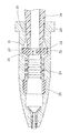
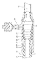
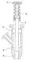
図1に示すカテーテルアセンブリ10は、中空のイントロデューサニードル12、カテーテルハブ14、および、ニードルハブ16を含む。イントロデューサニードル12は、鋭利な先端チップ13を有し、カテーテルハブ14を通って延びる。可撓性のカテーテルチューブ18がカテーテルハブ14の遠位端から延びており、ニードル12がカテーテルチューブ18を通過する。可撓性のカテーテルチューブ18は、カテーテル開口を通って延びている。まず、ニードル12を患者の静脈に挿入する。カテーテルチューブ18は、ニードル12に続く静脈内にニードル12に沿って押し込まれる。カテーテルチューブ18が挿入された後、ニードル12は患者の静脈およびカテーテルハブ14から取り外され、ニードル12が廃棄されるときに、患者にカテーテルチューブ18を残す。
The
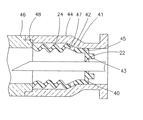
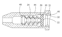
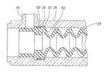
図2は、例示的なカテーテルハブアセンブリの断面図を示す。カテーテルハブアセンブリは、好ましくは、例えば、セプタム20およびベローズ24のような圧縮可能な部分を含む血液制御バルブ19を含んでいる。セプタム20は、カテーテルハブ28内に配置され、流体密封を形成するバルブとして機能する可撓性のカテーテルチューブ18に流体を選択的に受け入れる。換言すれば、バルブは、可撓性のカテーテルチューブ18を通る流体の流れを選択的に許容するか、または遮断する。
FIG. 2 shows a cross-sectional view of an exemplary catheter hub assembly. The catheter hub assembly preferably includes a
セプタム20は、本明細書で説明されるいずれの実施形態においても使用することができる。当業者に理解されるように、他のセプタム構成を使用することもできる。カテーテルチューブ18が最初に患者に挿入され、イントロデューサニードル12が取り外されると、セプタム20は、血液がチャネルを通って遠位端から流出することを防止する。セプタム20は弾性材料から、例えばシリコーンゴムから作られ、バルブを形成する。他の弾性材料を使用してもよく、必要に応じて非弾性材料をセプタム20に組み込んでもよい。
The
セプタム20は、予め形成された開口22または開かれたスリットを含む。セプタム20の予め形成された開口22は、セプタム20が最初に製造されたときに、または、その後の機械加工または切断作業において形成されることが好ましい。したがって、セプタム20がその自然の、圧縮されていない、自由なまたは弛緩された状態にあるとき、予め形成された開口22は開いており、セプタム20を開放位置とし、および、開いた流体路として作用する。
The
一方、セプタム20が予め形成された開口22の周りで半径方向に圧縮されると、予め形成された開口22が閉じてシールし、セプタム20を閉鎖位置に配置する。一般に、従来技術のセプタムは自然状態で閉じており、穿孔され、変形され、または、開かれるように係合される必要がある。対照的に、本実施形態によるセプタム20は、自然状態で開いており、係合して閉じている。
On the other hand, when the
セプタム20は、ばね部材として作用するベローズ24を含む。ベローズ24の軸方向ばねは、単にチューブであってもよく、好ましくは、ベローズ24が予測可能に弾性的に圧縮され、なおかつセプタム20が動作するのに十分なばね力を提供することができる成形起伏、または、その他の形状を含むことができる。ベローズ24は自然状態で拡張され、作動中に圧縮されて、セプタム20が開放位置と閉鎖位置の間を移動することを可能にする。
The
ベローズ24は、好ましくは弾性材料、例えばシリコーンマッバーで作られる。他の弾性材料を使用してもよく、必要に応じて非弾性材料をベローズ24に組み込んでもよい。一実施形態によれば、ベローズ24は、コイルばねのようなばね部材によって交換されまたは増強され、カテーテルハブアセンブリに用いられ、セプタム20の予備形成された開口22と協働する。
セプタム20は、取付面26をさらに含む。取付面26は、カテーテルハブアセンブリ内の位置にセプタム20を固定する。具体的には、取付面26は、セプタム20の他の部分と比較してより剛性的である。取付面26もまた、カテーテルハブ28の内径内で拡張する。そのような拡張は、セプタム20を固定するクランプ力を提供し、セプタム20が変位しないように摩擦を増加させる。ベローズ24は、取付面26と予め形成された開口22の間に配置される。したがって、セプタム20の取付面26を固定した後、セプタム20の車は、弛緩された位置と圧縮された位置の間で動作する。
図2に示すように、カテーテルハブ28の遠位端は、カテーテル開口を含み、近位端は、ルアーコネクタ開口を含む。カテーテルハブ28の近位端の内面はチャネルを取り囲んでおり、チャネルは、カテーテルハブ28を通る流体の通過を可能にする。カテーテルハブ28の外面は、ルアーコネクタ34をカテーテルハブ28に固定するための1つ以上の突起を含む。突起は、ルアーコネクタ34とのネジ接続を形成してもよく、または、スナップ嵌めまたは他のねじれ接続によってルアーコネクタ34に接続してもよい。
As shown in FIG. 2, the distal end of the
標準接続の一例は、ルアーロック(LUER−LOK(登録商標))接続である。特定のタイプのルアーコネクタ34は、カテーテルハブ28に滑り嵌めを利用する。好ましくは、ルアーコネクタ34は、セプタム20に接触する前に、カテーテルハブ28内でかなりの距離を移動する。カテーテルハブ28の近位端における拡張された内径は、有利には、ルアーコネクタ34をカテーテルアセンブリの中心に合わせることを可能にする。カテーテルチューブ28は、カテーテルハブを通る流体の流れをユーザが観察できるように透明または半透明のポリマー材料から作製してもよく、または、不透明な材料から作製してもよい。
An example of a standard connection is a luer lock (LUER-LOK®) connection. Certain types of
カテーテルハブ28は、効果的な操作を提供するためにセプタム20と相互作用する様々な内径を含む。カテーテルハブ28は、自由直径30および圧縮直径32を含む。自由直径30は、圧縮直径32よりも大きい。自由直径30は、好ましくは面取りされた表面31によって圧縮直径32に接続される。セプタム20の予め形成された開口22を取り囲む表面が自由直径30に配置されるとき、セプタム20は、予め形成された開口22を流れる。一方、セプタム20の予め形成された開口22に面する表面が圧縮直径32および/または面取りされた表面31に配置されるとき、セプタム20は半径方向に圧縮され、予め形成された開口22を閉じさせおよびシールさせる。このことにより、セプタム20は、流体が予め形成された開口22を通って流れることができない閉鎖位置に配置される。
セプタム20は、例えばルアーコネクタ34によって閉鎖位置から開放位置に移動される。動作中、ルアーコネクタ34は、セプタム20と協働するより前に、カテーテルの遠位端の内径によって支持され、中心に合わせられる。ルアーコネクタ34が初めにセプタム20に接触すると、セプタム20の予め形成された開口22を取り囲む面が、この位置で、カテーテルハブ28の圧縮直径32および/または面取りされた表面31に配置され、セプタム20は、予め形成された開口22が閉鎖され、シールされた閉鎖位置にある。
The
セプタム20(開放位置)を開くために、使用者は、ルアーコネクタ34をカテーテルハブ28に押し込むことができ、このことにより、セプタム20の予め形成された開口22を取り囲む表面をカテーテルハブ28の自由直径30に押し込み、この位置では、ベローズ24は、セプタム20が半径方向に膨張し、予め形成された開口22を開き、流体が流れる通路を可能にする。同時に、セプタム20はベローズ24において軸方向に圧縮され、増加した軸方向の反作用の力を生成する。
To open the septum 20 (open position), the user can push the
その後、使用者がルアーコネクタ34をカテーテルハブ28から取り外すと、セプタム20のベローズ24が膨張し、セプタム20の予め形成された開口22を取り囲んでいる表面を面取りされた表面31内に入らせ、および/または、カテーテルハブ28の圧縮直径32を閉鎖位置内に入らせる。カテーテルハブ28の閉鎖位置において、ベローズ24は、部分的に軸方向に圧縮され続けて、セプタム20が、自由直径30、面取りされた表面31および圧縮直径32を持つシール面を確立するように力を生成することが好ましい。
Thereafter, when the user removes the
さらに、セプタム20は、完全弛緩位置と完全圧縮位置の間で動作するだけではない。セプタム20はまた、より圧縮されていない位置とより圧縮された位置の間で動作することができる。セプタム20は、より圧縮されていないときには(部分的に)圧縮され、より圧縮されているときには閉じられていてもよい。同様に、セプタム20は、弛緩されていない位置およびより弛緩された位置で動作することができる。セプタム20は、より弛緩されたときに開かれてもよく、部分的に弛緩されていなくても開かれてもよい。そのような汎用性は、セプタム20が受ける様々な圧力勾配において有用であり得る。図2に示される例示的なセプタムの特徴は、本明細書で開示される他の例示的実施形態の特徴と組み合わせることができる。
Furthermore, the
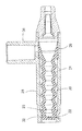
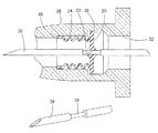
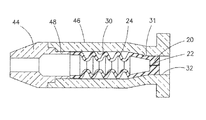
図3および図4は、別の例示的実施形態によるカテーテルハブアセンブリのセプタム40を示す。図3は開放位置にあるセプタム40を示し、図4は閉鎖位置にあるセプタム40を示す。詳細には、カテーテルハブアセンブリは、第1のカテーテルハブ部44と第2のカテーテルハブ部46を含む2ピースカテーテルハブを有する。2ピース構造は、有利には、組立の改善と製造コスト低減をもたらす。第2のカテーテルハブ部46はまた、セプタム40の組立及び作動のための停止面として作用するアンダーカットされた表面48を含む。
3 and 4 show a
セプタム40はシール面41を含み、シール面41は、第1のカテーテルハブ部44の内径45および面取りされた表面47と接触する。シール面41は、予め形成された開口22とベローズ24の間に配置されている。セプタム40のシール面41は、その外周に沿って離間した複数の貫通孔42を含む。複数の貫通孔42には、様々な形状、サイズ、および、間隔が考えられる。セプタム40の近位端には、例えばルアーコネクタ34と嵌合するボス43が含まれる。ボス43およびルアーコネクタ34は、セプタム40の動作を補助する。セプタム40はまた、セプタム40の後述する適切な動作のためのベローズ24を含む。
The
図4に示すように、カテーテルハブアセンブリが閉状態にあるとき、セプタム40のベローズ24は、第2のカテーテルハブ部46のアンダーカットされた表面48からの力を生成し、セプタム40を通って、面取りされた表面47および第1のカテーテルハブ部44の内径45へと移動する。この力によって、セプタム40のシール面41は、第1のカテーテルハブ部44の内径45および面取りされた表面47と係合する。この結果、流体はセプタム40を通過することができない。
As shown in FIG. 4, when the catheter hub assembly is in the closed state, the
セプタム40のボス43は、係合したときにルアーコネクタ34の中心と合わせられる。ルアーコネクタ34がセプタム40のボス43と係合し、ベローズ24によって印加される圧力に打ち勝つのに十分な軸方向の圧力を印加しると、セプタム40は内径45から離れ、第1のカテーテルハブ部44の第2の端部に係合する。したがって、セプタム40は、図3に示された開放位置に入る。セプタム40が開くと、流体はシール面41と第1のカテーテルハブ部44の間を移動する。次に、流体は複数の貫通孔42を通って移動し、カテーテルハブアセンブリに入る。ルアーコネクタ34から軸方向圧力を解放すると、ベローズ24内の圧力により、図4に示すようにセプタム40が閉鎖位置に戻り、流体がカテーテルハブアセンブリに入ることが防止される。図3および図4に示された例示的なセプタムの特徴は、本明細書で開示される他の例示的実施形態の特徴と組み合わせることができる。
The
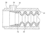
図5〜図7は、図2のカテーテルハブアセンブリの好ましい実施形態を示し、本実施形態はサイドポート36をさらに含む。本実施形態のカテーテルハブアセンブリは、図2で説明したのと同様の方法で動作する。しかし、セプタム20の取付面26は、サイドポート36を通って入る流体の流れを選択的に許容しまたは遮断する。予め形成された開口22および取付面26におけるセプタム20の選択的な開閉は、互いに独立して動作する。
5-7 illustrate a preferred embodiment of the catheter hub assembly of FIG. 2 and this embodiment further includes a
取付面26は、上述した実施形態で説明したような半径方向の拡張による、その剛性及びその適用された密封力によって、サイドポート36をシールする。図7に示すように、セプタム20を取付面26に選択的に開口させるために、取付面26は、その面の全長にわたって可変の厚さを有する。好ましくは、取付面26は、セプタム20の遠位端に近づくにつれて厚さが薄くなる。このようにして、取付面26の柔軟性及び剛性は、効果的な動作のために、以下に説明するように調整される。
The mounting
作動中、サイドポート36からの流体力が(材料の剛性によって)取付面26の反作用力に打ち勝つと、取付面26のセプタム20が撓んで開いて(図7参照)、流体がカテーテルハブ28に入る(開放位置)。サイドポート36からの流体力が(材料の剛性によって)取付面26の反作用力よりも小さいときは、取付面26のセプタム20は閉じられ(図5および図6参照)、その初期状態に戻る(閉鎖位置)。したがって、セプタム20は、有利には、カテーテルおよびサイドポートからの流体の流れを同時に且つ独立に調整することができる。
In operation, when the fluid force from the
セプタム20は、流体が様々な異なる動作モードでルアーコネクタ34およびサイドポート36を介してカテーテルハブ28に入ることを可能にすることができる。例えば、図6に示すように、予め形成された開口22は開放位置にあることができ、取付面26は閉鎖位置にあることができる。別の動作モードでは、図7に示すように、予め形成された開口22および取付面26は両方とも開放位置にあることができる。さらに、予め形成された開口22は閉鎖位置にあり、取付面26は開放位置にあることができる。最後に、図5に示すように、予め形成された開口22と取付面26の両方を閉鎖位置にすることもできる。図5〜7に示される例示的なセプタムの特徴は、本明細書で開示される他の例示的実施形態の特徴と組み合わせることができる。
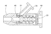
図8は、直径が縮小したニードル38を有するカテーテルハブアセンブリの例示的実施形態を示す。カテーテルアセンブリの保管中、セプタム20の弾性が長期間にわたって損なわれる可能性があることから、セプタム20を閉鎖位置に配置することが望ましくない場合がある。換言すれば、セプタム20が長期間にわたってカテーテルハブ28の圧縮直径32内に配置された場合、セプタム20が圧縮セットに入り、開放位置と閉鎖位置の間で効果的に移行する能力を失い始める可能性がある。セプタム20が圧縮セットに入ると、セプタム20の経年シール強度が損なわれることがある。
FIG. 8 illustrates an exemplary embodiment of a catheter hub assembly having a
上述の潜在的な問題に対処するために、一実施形態によれば、セプタム20はカテーテルハブ28の自由直径30に配置され、開放位置に配置される。一方、ニードル38はカテーテルアセンブリの内側に配置され、ニードル38の径縮小部39は、カテーテルハブ28の自由直径30に位置付けられ、そこに、セプタム20の予め形成された開口22が配置される。この開放位置は保管中も維持される。したがって、カテーテルアセンブリは、セプタム20の予め形成された開口22に最小の応力を印加しつつ、長期間の間、保管され得る。
To address the potential problems described above, according to one embodiment, the
カテーテルアセンブリが使用可能な状態になると、ニードル38は、可撓性のカテーテルチューブ18の患者への配置を助けることができる。その後、ニードル38が除去され、そしてカテーテルアセンブリは、上記の実施形態で説明したのと同様の方法で動作することができる。したがって、ニードル38内の直径39が縮小しても、流体の流れにまたはカテーテルアセンブリの全体的な動作には影響がない。図8に示された例示的なニードルの特徴は、本明細書で開示された他の例示的実施形態の特徴と組み合わせることもできる。
When the catheter assembly is ready for use, the
図9に示すように、複数の軸方向流路54をセプタム50の遠位端に配置し、予め形成された開口52をセプタム50の近位端に配置することができる。流路54は、セプタム50の外周に配置される。5つの流路54が示されているが、様々な数および位置が考えられる。流路54は、セプタム50が開かれていないときに血液がセプタム50に入り、空気がカテーテルハブ28の前部のセプタム50の遠位の空間から逃げることができるように、適切な幅と深さを有している。同時に、流路54は、血液が(少なくともある程度の期間、)セプタム50を通過して出て行くことを防ぐのに十分な大きさの寸法である。このような構成は、血液中の分子間力が空気中の分子間力よりも大きいことにより可能である。図9に示された例示的なセプタムの特徴は、本明細書で開示される他の実施形態の特徴と組み合わせることができる。
As shown in FIG. 9, a plurality of axial channels 54 can be disposed at the distal end of the septum 50 and a
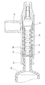
図10及び図11は、サイドポート36を有する2ピースカテーテルハブアセンブリの断面図を示す。カテーテルハブアセンブリは、第1のカテーテルハブ部44および第2のカテーテルハブ部46を含む。第1のカテーテルハブ部44はサイドポート36を含む。サイドポート36の中心線は、好ましくは、カテーテルハブアセンブリの中心線に対して90度未満の角度で配置される。より好ましくは、サイドポート36の中心線は、カテーテルハブアセンブリの中心線に対して45度の角度をなす。
10 and 11 show a cross-sectional view of a two-piece catheter hub assembly having a
サイドポート36は、第1のカテーテルハブ部44の端部近傍に配置されている。第2のカテーテルハブ部46は、第1のカテーテルハブ部44の遠位端と接触するアンダーカットされた表面48を含む。第1および第2のカテーテルハブ部44,46が組み立てられると、これらは、好ましくは溶接継手によって共に固定されるが、プレス嵌め、スナップ嵌め、または、代替的に接着剤接合によって固定することができる。上述したようにサイドポート36を傾斜させることで、溶接プロセスが行われるのに十分なクリアランスが提供される。
The
カテーテルハブアセンブリが一緒に溶接された後、工作装置56を使用して、セプタム20の、カテーテルハブアセンブリへの組み立てを補助する。具体的には、図11に示すように、工作装置56は、セプタム20の遠位端のノッチ51によってセプタム20に固定される。工作装置56は、その後、図10に示すように、セプタム20が第2のカテーテルハブ部46のアンダーカットされた表面48に接触するまで、セプタム20をカテーテルハブアセンブリ内に引っ張る。その後、工作装置56は取り外され、カテーテルハブアセンブリは上記の実施形態で説明したのと同様の方法で動作する。したがって、セプタム20は、近位端およびサイドポート36でカテーテルハブアセンブリを密封することができる。図10および図11に示された例示的なカテーテルハブのアセンブリ方法の特徴は、本明細書で開示される他の例示的実施形態の特徴と組み合わせることができる。
After the catheter hub assembly is welded together, the
図12は、2ピースカテーテルハブアセンブリの代替実施形態を示す。2ピースカテーテルハブアセンブリは、第1のカテーテルハブ部44および第2のカテーテルハブ部46を含む。第1のカテーテルハブ部44は、自由直径30およびアンダーカットされた表面48を含み、第2のカテーテルハブ部46は、圧縮直径32および面取りされた表面31を含む。
FIG. 12 shows an alternative embodiment of a two-piece catheter hub assembly. The two piece catheter hub assembly includes a first
バルブ19が第1のカテーテルハブ部44に組み付けられ、アンダーカットされた表面48と接触した後、第2のカテーテルハブ部46は、例えば圧入によって第1のカテーテルハブ部44の内径に固定される。したがって、予め形成された開口22およびベローズ24を有するセプタム20は、第1のカテーテルハブ部44の自由直径30から、面取りされた表面31および第2のカテーテルハブ部46の圧縮直径32に移動して、上述の実施形態で説明したのと同様の方法で閉鎖位置に移動される。図12に示される例示的なカテーテルハブアセンブリの特徴は、本明細書で開示される他の例示的実施形態の特徴と組み合わせることができる。
After the
図13は、2ピースカテーテルハブアセンブリの代替実施形態を示す。カテーテルハブアセンブリは、第1のカテーテルハブ部44および第2のカテーテルハブ部46を含む。第1のカテーテルハブ部44は、特定のニードルゲージを受け入れる大きさのノーズを含む。第1のカテーテルハブ部44のノーズは、様々なニードルゲージ用の寸法にすることができると考えられる。第1のカテーテルハブ部44はまた、後述するようにセプタム20と相互作用するアンダーカットされた表面48を含む。第2のカテーテルハブ部46は、面取りされた表面31を介して圧縮直径32にネッキングされた自由直径30を含む。
FIG. 13 shows an alternative embodiment of a two-piece catheter hub assembly. The catheter hub assembly includes a first
カテーテルハブアセンブリは、最初にバルブ19を第2のカテーテルハブ部46に配置することによって組み立てられる。セプタム20の予め形成された開口22は、第2のカテーテルハブ部46の圧縮直径32内に配置される。続いて、第1のカテーテルハブ部44は、第2のカテーテルハブ部46の遠位端に挿入され、例えば、溶接継手によって固定される。したがって、セプタム20内のベローズ24は、セプタム20が第1のカテーテルハブ部44のアンダーカットされた表面48と接触することを可能にし、上記の実施形態で説明したのと同様の方法で動作する。図13に示された例示的なカテーテルハブアセンブリの特徴は、本明細書で開示される他の例示的実施形態の特徴と組み合わされてもよい。
The catheter hub assembly is assembled by first placing the
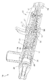
図14は、本明細書の実施形態において開示されるカテーテルアセンブリと適合する例示的なニードル安全機構60を示す。ニードル安全機構60は、ニードル64の遠位先端68の近くに配置された変形部69を有するニードル64を含んでいる。ニードル安全機構60はまた、カテーテルハブと係合するためのインターロックとして作用するタブ62を有するニードルシールド63を含む。スリーブ65およびばね66が、ニードル安全機構60内に配置されて、スリーブから半径方向の力を印加し、離脱時にばね66から軸方向に移動させる。安全機構60の動作を以下に説明する。
FIG. 14 illustrates an exemplary
カテーテルアセンブリは、図1に示したように、ニードル64がカテーテルハブを突き抜けている間、ニードル安全機構60に係合される。具体的には、ニードル安全機構60のタブ62は、ニードル安全機構60が不適切に取り外されることを防止するために、カテーテルハブの内径の突起に係合される(図17および図18参照)。
The catheter assembly is engaged with a
カテーテルチューブが患者の静脈内に配置され、使用者がニードルをカテーテルハブから取り外すと、ニードル安全機構60内のタブ62が収束する。タブ62が移動すると、ばね66が解放されて軸方向の圧力をスリーブ65に印加し、ニードル安全機構60をカテーテルハブから分離させる。スリーブ65がニードルシールド63に沿って軸方向に移動すると、スリーブ65はニードルシールド63に半径方向の力を印加し、ニードルシールド63を閉じさせる。続いて、スリーブ65およびばね66がニードル安全機構60のニードルシールド63の上に延び、ニードル安全機構60のニードルシールド63にニードル64を固定する。したがって、ニードル64は、ばね66が引き戻されない限り、ニードル安全機構60のニードルシールド63から誤って取り外されることがない。
When the catheter tube is placed in the patient's vein and the user removes the needle from the catheter hub, the
使用者がニードル安全機構60からニードル64を引っ張ると、ニードル変形部69はニードル安全機構60の内部端壁71に接触する。したがって、ユーザは、ニードル64を引っ張って、ニードル安全機構60をカテーテルアセンブリのカテーテルハブから引っ張り出し、取り外すことができる。また、ニードル変形部69および内部端壁71は、ニードル64がニードルシールド63から分離することを防止する。
When the user pulls the
図14に示される例示的なニードル安全機構の特徴は、本明細書で開示される他の例示的実施形態の特徴と組み合わせることができる。さらに、異なるタイプの様々なニードル安全機構が、本明細書で開示されたカテーテルアセンブリと適合し得る。 The features of the exemplary needle safety mechanism shown in FIG. 14 can be combined with the features of other exemplary embodiments disclosed herein. In addition, various types of different needle safety mechanisms may be compatible with the catheter assemblies disclosed herein.
図15は、サイドポート36を有するカテーテルハブアセンブリを密封するOリング58の例示的実施形態を示す。具体的には、取付面26を有するセプタム50が、サイドポート36を密封するために使用される。高い流体圧力下でのサイドポート36を伴うセプタム50の動作は、上記の実施形態についてと同様に説明される。
FIG. 15 illustrates an exemplary embodiment of an O-
高い流体圧力がサイドポート36を介して供給される場合、取付面26は撓み、流体がセプタム50に入ることを可能にする。取付面26の撓みによって、意図に反して流体漏れが生じる可能性がある。したがって、Oリング58は、サイドポート36に隣接して、または、セプタム50とカテーテルハブの間に配置される。Oリング58は、セプタム50とカテーテルハブ28の間のシール面を強化し、カテーテルハブ28に入るときに流体がセプタム50の外側に流れないことを保証する。このようにして、サイドポート36から入る流体は、セプタム50と適切に調節される。図15に示される例示的なシール構成の特徴は、本明細書で開示される他の例示的実施形態の特徴と組み合わせることができる。
When high fluid pressure is supplied through the
図16は、サイドポート36を有するカテーテルハブアセンブリをシールする圧縮リング70の例示的実施形態を示す。具体的には、取付面26を有するセプタム20を使用して、上記実施形態で説明したようにサイドポート36をシールする。圧縮リング70は、図15の実施形態で説明したのと同様の方法で、サイドポート36からの高い流体圧力下でのシールを改善するために使用される。
FIG. 16 illustrates an exemplary embodiment of a
圧縮リング70は、サイドポート36に隣接して配置される。圧縮リング70は、例えばセプタム20における圧入によって、セプタム20をカテーテルハブ28に密封する。圧入によってセプタム20とカテーテルハブ28の間の圧力が上昇する。この増大した圧力は、セプタム20を締め付け、カテーテルハブ28に入るときに流体がセプタム20の外側に流れることができる流体漏れ経路の可能性を低減する。このようにして、サイドポート36からの流体はセプタム20に入り、適切に調整される。図16に示された例示的なシール構成の特徴は、本明細書で開示する他の例示的実施形態の特徴と組み合わせることができる。
The
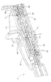
図17および図18は、カテーテルアセンブリ10およびニードル安全機構60の好ましい実施形態を示す。本実施形態は、図2および図3〜図7に示すようなカテーテルアセンブリ、および、図14に同様に示されたニードル安全機構60を組み込んでいる。
17 and 18 illustrate a preferred embodiment of the
具体的には、ニードル安全機構60がカテーテルアセンブリ10に係合されると、セプタム20は開放位置にある。カテーテルチューブが患者の静脈内にセットされた後、ニードル64が取り外される。ニードル64がカテーテルハブ28から除去され、ニードル64の遠位先端68がニードルシールド63に入ると、ニードルシールド63のタブ62が収縮してカテーテルハブ28を外す。タブ62が収束するにつれて、ばね66は、ニードル安全機構60を閉じるように軸方向に延び、ニードル64の遠位先端68に遠位障壁を提供し、遠位先端68が遠位で再露出することを防止する。
Specifically, when the
外側ハウジング61は、ニードル安全機構60のこの実施形態を取り囲む。しかしながら、ニードル安全機構60はスリーブ65を含まない。ニードルシールド63のタブ62がカテーテルハブ28から外れると、ばね66はテーパ付きニードルシールド63の外側段付面67から解放されることが有利である。したがって、ばね66は、外側段付面67を越えて軸方向に移動し、ニードルシールド63の外側を取り囲み続ける。ばね66は、最終的にニードルシールド63のタブ62まで伸びて接触する。このような構成により、ニードルシールド63を閉鎖位置で半径方向にロックして、ニードル64が出ることを防止する。
ニードル安全機構60とカテーテルハブ28との係合が解除されると、セプタム20は閉鎖位置に移動する。具体的には、ベローズ24は軸方向の圧力を印加し、セプタム20を圧縮直径32内に移動させる。図17および図18に示す例示的なカテーテルアセンブリおよびニードル安全機構の特徴は、本明細書で開示される他の例示的実施形態の特徴と組み合わせることができる。
When the engagement between the
本発明の原理およびその実用的な応用を説明する目的で、特定の例示的実施形態の前述の詳細な説明が提供されており、当業者が様々な実施形態について本発明を理解することを可能にし、特定の使用が意図されている。この説明は、網羅的であること、または開示された厳密な実施形態に本発明を限定することを必ずしも意図するものではない。本明細書で開示された実施形態および/または要素のいずれも、互いに組み合わせて、特に開示されていない様々な追加の実施形態を形成することができる。したがって、追加の実施形態が可能であり、本明細書および本発明の範囲内に包含されることが意図される。本明細書は、別の方法で達成され得るより一般的な目標を達成するための具体的な例を記載する。 For the purpose of illustrating the principles of the invention and its practical application, the foregoing detailed description of specific exemplary embodiments is provided to enable those skilled in the art to understand the invention in various embodiments. And is intended for specific use. This description is not intended to be exhaustive or to limit the invention to the precise embodiments disclosed. Any of the embodiments and / or elements disclosed herein can be combined with each other to form various additional embodiments not specifically disclosed. Accordingly, additional embodiments are possible and are intended to be included within the scope of the specification and invention. This specification describes specific examples to achieve a more general goal that may be achieved in another way.
この出願で使用されているように、用語「前方」、「後方」、「上方」、「下方」、「上向き」、「下向き」および他の方向指定子は、本発明の例示的実施形態の説明を容易にするためのものであり、本発明の例示的実施形態の構造を任意の特定の位置または向きに限定することを意図しない。「実質的に」または「およそ」のような程度の用語は、所与の値の外の妥当な範囲、例えば記載された実施形態の製造、組み立ておよび使用に関連する一般的な公差を指すと理解される。 As used in this application, the terms “forward”, “backward”, “upward”, “downward”, “upward”, “downward”, and other directional specifiers are used in the exemplary embodiments of the present invention. For ease of explanation, it is not intended that the structure of the exemplary embodiments of the invention be limited to any particular position or orientation. Terms such as “substantially” or “approximately” refer to a reasonable range outside a given value, eg, general tolerances associated with the manufacture, assembly and use of the described embodiments. Understood.
Claims (17)
カテーテルと、
鋭い遠位先端を有するニードルと、
カテーテルハブであって、それを貫通する前記ニードルを有する前記カテーテルに接続されており、
予め形成された開口を有するバルブであって、前記カテーテルを通る流体の流れを選択的に許容または遮断するバルブと、
前記バルブを閉鎖する第1の内径と、
前記第1の内径よりも大きい第2の内径であって、前記バルブを開放する第2の内径を含むカテーテルハブと
を備え、
前記バルブは、前記バルブを軸方向に圧縮して前記カテーテルハブの前記第2の内径と係合したときに、開放位置にあり、および、
前記バルブは、前記バルブを解放して前記カテーテルハブの前記第1の内径と係合したときに、閉鎖位置にある、カテーテルアセンブリ。 A catheter assembly,
A catheter;
A needle having a sharp distal tip;
A catheter hub connected to the catheter having the needle therethrough;
A valve having a pre-formed opening for selectively allowing or blocking fluid flow through the catheter;
A first inner diameter that closes the valve;
A catheter hub including a second inner diameter that is larger than the first inner diameter and that opens the valve;
The valve is in an open position when the valve is axially compressed to engage the second inner diameter of the catheter hub; and
The catheter assembly, wherein the valve is in a closed position when the valve is released to engage the first inner diameter of the catheter hub.
前記ニードルの前記縮小された直径は、前記バルブの圧縮設定を最小にするための貯蔵中に、前記バルブの前記予め形成された開口と係合する、請求項1に記載のカテーテルアセンブリ。 The needle includes a reduced diameter;
The catheter assembly of claim 1, wherein the reduced diameter of the needle engages the pre-formed opening of the valve during storage to minimize the compression setting of the valve.
カテーテルと、
鋭い遠位先端を有するニードルと、
カテーテルハブであって、それを貫通する前記ニードルを有する前記カテーテルに接続されており、
予め形成された開口を有するバルブであって、前記カテーテルを通る流体の流れを選択的に許容または遮断するバルブと、
前記バルブを閉鎖する第1の内径と、
前記第1の内径よりも大きい第2の内径であって、前記バルブを開放する第2の内径を含むカテーテルハブと
前記ニードルを収容するニードルシールドと
を備え、
前記バルブは、前記ニードルシールドを前記カテーテルハブに係合させ、および、前記バルブを軸方向に圧縮して前記カテーテルハブの前記第2の内径内に入れたときに、開放位置にあり、および、
前記バルブは、前記ニードルシールドを前記カテーテルハブから係合離脱させて、前記バルブが前記カテーテルハブの前記第1の内径と係合したときに、閉鎖位置にある、カテーテルアセンブリ。 A catheter assembly,
A catheter;
A needle having a sharp distal tip;
A catheter hub connected to the catheter having the needle therethrough;
A valve having a pre-formed opening for selectively allowing or blocking fluid flow through the catheter;
A first inner diameter that closes the valve;
A catheter hub including a second inner diameter that is larger than the first inner diameter and that opens the valve; and a needle shield that houses the needle;
The valve is in an open position when the needle shield is engaged with the catheter hub and the valve is axially compressed into the second inner diameter of the catheter hub; and
The catheter assembly, wherein the valve is in a closed position when the needle shield is disengaged from the catheter hub and the valve engages the first inner diameter of the catheter hub.
前記ニードルの前記縮小された直径は、前記バルブの圧縮設定を最小にするための貯蔵中に、前記バルブの前記予め形成された開口と係合する、請求項1に記載のカテーテルアセンブリ。 The needle includes a reduced diameter;
The catheter assembly of claim 1, wherein the reduced diameter of the needle engages the pre-formed opening of the valve during storage to minimize the compression setting of the valve.
Priority Applications (1)
| Application Number | Priority Date | Filing Date | Title |
|---|---|---|---|
| JP2022085254A JP2022109322A (en) | 2015-09-18 | 2022-05-25 | Safety IV Catheter with Molded Open Blood Control Valve |
Applications Claiming Priority (3)
| Application Number | Priority Date | Filing Date | Title |
|---|---|---|---|
| US201562220653P | 2015-09-18 | 2015-09-18 | |
| US62/220,653 | 2015-09-18 | ||
| PCT/US2016/052232 WO2017049150A1 (en) | 2015-09-18 | 2016-09-16 | Safety iv catheter with molded-open blood control valve |
Related Child Applications (1)
| Application Number | Title | Priority Date | Filing Date |
|---|---|---|---|
| JP2022085254A Division JP2022109322A (en) | 2015-09-18 | 2022-05-25 | Safety IV Catheter with Molded Open Blood Control Valve |
Publications (2)
| Publication Number | Publication Date |
|---|---|
| JP2018531663A true JP2018531663A (en) | 2018-11-01 |
| JP7117997B2 JP7117997B2 (en) | 2022-08-15 |
Family
ID=58289613
Family Applications (2)
| Application Number | Title | Priority Date | Filing Date |
|---|---|---|---|
| JP2018514302A Active JP7117997B2 (en) | 2015-09-18 | 2016-09-16 | Safety IV catheter with molded open blood control valve |
| JP2022085254A Pending JP2022109322A (en) | 2015-09-18 | 2022-05-25 | Safety IV Catheter with Molded Open Blood Control Valve |
Family Applications After (1)
| Application Number | Title | Priority Date | Filing Date |
|---|---|---|---|
| JP2022085254A Pending JP2022109322A (en) | 2015-09-18 | 2022-05-25 | Safety IV Catheter with Molded Open Blood Control Valve |
Country Status (11)
| Country | Link |
|---|---|
| US (1) | US10695551B2 (en) |
| EP (2) | EP4112113A1 (en) |
| JP (2) | JP7117997B2 (en) |
| CN (1) | CN108025166B (en) |
| AU (1) | AU2016323969B2 (en) |
| BR (1) | BR112018005242B1 (en) |
| CA (1) | CA2998359C (en) |
| ES (1) | ES2927498T3 (en) |
| MX (1) | MX2018002918A (en) |
| NZ (1) | NZ740854A (en) |
| WO (1) | WO2017049150A1 (en) |
Cited By (2)
| Publication number | Priority date | Publication date | Assignee | Title |
|---|---|---|---|---|
| JP2023502599A (en) * | 2019-11-12 | 2023-01-25 | ベクトン・ディキンソン・アンド・カンパニー | Assisted catheter advancement |
| JP2023520013A (en) * | 2020-03-31 | 2023-05-15 | ベクトン・ディキンソン・アンド・カンパニー | CATHETER ASSEMBLY WITH SLIDABLE SEPTUM AND RELATED SYSTEMS AND METHODS |
Families Citing this family (8)
| Publication number | Priority date | Publication date | Assignee | Title |
|---|---|---|---|---|
| ES2792025T3 (en) | 2015-10-28 | 2020-11-06 | Carefusion 303 Inc | Closed IV access device with needleless port and connector |
| US12246157B2 (en) * | 2019-01-14 | 2025-03-11 | Becton, Dickinson And Company | Needleless access connector facilitating instrument delivery to a catheter assembly |
| EP4028104A4 (en) | 2019-09-10 | 2023-12-13 | MedSource International LLC | An intravenous catheter device |
| US11660253B2 (en) * | 2019-09-18 | 2023-05-30 | Medisarang Co., Ltd. | Device for extracting platelet rich plasma |
| WO2022172281A1 (en) | 2021-02-10 | 2022-08-18 | Neeraj Gupta | Intravenous cannula |
| US12337123B2 (en) | 2021-05-06 | 2025-06-24 | Medsource Labs, Llc | Safety intravenous cannula |
| WO2022251015A1 (en) * | 2021-05-27 | 2022-12-01 | Becton, Dickinson And Company | Retainer element to secure a catheter adapter valve |
| US12186497B2 (en) | 2022-01-14 | 2025-01-07 | Medsource International Llc | Intravenous cannula |
Citations (5)
| Publication number | Priority date | Publication date | Assignee | Title |
|---|---|---|---|---|
| JP2002263197A (en) * | 2001-03-12 | 2002-09-17 | Medikit Kk | Indwelling catheter |
| JP2006512166A (en) * | 2002-12-30 | 2006-04-13 | アラリス メディカル システムズ インコーポレイテッド | Safety catheter system and method |
| JP2012512726A (en) * | 2008-12-19 | 2012-06-07 | アイシーユー・メディカル・インコーポレーテッド | Medical connector with closable luer connector |
| WO2014074929A1 (en) * | 2012-11-12 | 2014-05-15 | Icu Medical, Inc. | Medical connector |
| WO2015112426A1 (en) * | 2014-01-21 | 2015-07-30 | Becton, Dickinson And Company | Ported catheter adapter having combined port and blood control valve with venting |
Family Cites Families (16)
| Publication number | Priority date | Publication date | Assignee | Title |
|---|---|---|---|---|
| US5549651A (en) | 1994-05-25 | 1996-08-27 | Lynn; Lawrence A. | Luer-receiving medical valve and fluid transfer method |
| US5470319A (en) * | 1994-06-20 | 1995-11-28 | Critical Device Corporation | Needleless injection site |
| NZ286445A (en) * | 1995-05-16 | 1997-12-19 | Ivac Corp | Needleless luer connector: deformable piston occludes bore |
| US5814024A (en) * | 1996-11-27 | 1998-09-29 | Elcam Plastics | Needleless valve |
| US5967490A (en) | 1997-01-08 | 1999-10-19 | Vadus, Inc. | Catheter hubs having a valve |
| US6663592B2 (en) | 2001-09-06 | 2003-12-16 | Medex, Inc. | Catheter introducer assembly having safety shielded needle |
| ES2782875T3 (en) * | 2002-06-20 | 2020-09-16 | Becton Dickinson Co | Catheter and introducer needle assembly with needle guard |
| US7585288B2 (en) * | 2004-01-23 | 2009-09-08 | Genico, Inc. | Trocar and cannula assembly having conical valve and related methods |
| US7918863B2 (en) * | 2005-06-24 | 2011-04-05 | Conceptus, Inc. | Minimally invasive surgical stabilization devices and methods |
| US8343104B2 (en) | 2007-06-29 | 2013-01-01 | Medical Components, Inc. | Closable and openable catheter assembly and method of using same |
| US8486024B2 (en) * | 2011-04-27 | 2013-07-16 | Covidien Lp | Safety IV catheter assemblies |
| US8622967B2 (en) * | 2012-05-15 | 2014-01-07 | Becton, Dickinson And Company | Over-the-needle intravenous catheter assembly with integrated intravenous tubing |
| US9114231B2 (en) * | 2013-03-15 | 2015-08-25 | B. Braun Melsungen Ag | Valved catheter assemblies and related methods |
| CN203724591U (en) | 2013-03-15 | 2014-07-23 | B.布劳恩梅尔松根股份公司 | Valve-controlled catheter assembly |
| US8979802B2 (en) | 2013-03-15 | 2015-03-17 | B. Braun Melsungen Ag | Safety IV catheter assembly with seal |
| US9381320B2 (en) | 2013-03-18 | 2016-07-05 | Becton, Dickinson And Company | Multiple-use intravenous catheter assembly septum and septum actuator |
-
2016
- 2016-09-16 CN CN201680053825.7A patent/CN108025166B/en active Active
- 2016-09-16 BR BR112018005242-6A patent/BR112018005242B1/en active IP Right Grant
- 2016-09-16 CA CA2998359A patent/CA2998359C/en active Active
- 2016-09-16 EP EP22192612.4A patent/EP4112113A1/en active Pending
- 2016-09-16 WO PCT/US2016/052232 patent/WO2017049150A1/en not_active Ceased
- 2016-09-16 JP JP2018514302A patent/JP7117997B2/en active Active
- 2016-09-16 AU AU2016323969A patent/AU2016323969B2/en active Active
- 2016-09-16 NZ NZ740854A patent/NZ740854A/en unknown
- 2016-09-16 MX MX2018002918A patent/MX2018002918A/en unknown
- 2016-09-16 US US15/760,816 patent/US10695551B2/en active Active
- 2016-09-16 ES ES16847438T patent/ES2927498T3/en active Active
- 2016-09-16 EP EP16847438.5A patent/EP3349840B1/en active Active
-
2022
- 2022-05-25 JP JP2022085254A patent/JP2022109322A/en active Pending
Patent Citations (5)
| Publication number | Priority date | Publication date | Assignee | Title |
|---|---|---|---|---|
| JP2002263197A (en) * | 2001-03-12 | 2002-09-17 | Medikit Kk | Indwelling catheter |
| JP2006512166A (en) * | 2002-12-30 | 2006-04-13 | アラリス メディカル システムズ インコーポレイテッド | Safety catheter system and method |
| JP2012512726A (en) * | 2008-12-19 | 2012-06-07 | アイシーユー・メディカル・インコーポレーテッド | Medical connector with closable luer connector |
| WO2014074929A1 (en) * | 2012-11-12 | 2014-05-15 | Icu Medical, Inc. | Medical connector |
| WO2015112426A1 (en) * | 2014-01-21 | 2015-07-30 | Becton, Dickinson And Company | Ported catheter adapter having combined port and blood control valve with venting |
Cited By (3)
| Publication number | Priority date | Publication date | Assignee | Title |
|---|---|---|---|---|
| JP2023502599A (en) * | 2019-11-12 | 2023-01-25 | ベクトン・ディキンソン・アンド・カンパニー | Assisted catheter advancement |
| JP7612686B2 (en) | 2019-11-12 | 2025-01-14 | ベクトン・ディキンソン・アンド・カンパニー | Assisted Catheter Advancement |
| JP2023520013A (en) * | 2020-03-31 | 2023-05-15 | ベクトン・ディキンソン・アンド・カンパニー | CATHETER ASSEMBLY WITH SLIDABLE SEPTUM AND RELATED SYSTEMS AND METHODS |
Also Published As
| Publication number | Publication date |
|---|---|
| WO2017049150A1 (en) | 2017-03-23 |
| MX2018002918A (en) | 2018-06-07 |
| EP4112113A1 (en) | 2023-01-04 |
| CN108025166B (en) | 2020-11-13 |
| BR112018005242B1 (en) | 2022-05-03 |
| ES2927498T3 (en) | 2022-11-07 |
| BR112018005242A2 (en) | 2018-10-02 |
| AU2016323969A1 (en) | 2018-04-12 |
| JP2022109322A (en) | 2022-07-27 |
| US10695551B2 (en) | 2020-06-30 |
| EP3349840A4 (en) | 2019-10-16 |
| EP3349840B1 (en) | 2022-08-31 |
| CA2998359A1 (en) | 2017-03-23 |
| AU2016323969B2 (en) | 2020-12-10 |
| US20180256885A1 (en) | 2018-09-13 |
| CA2998359C (en) | 2024-02-06 |
| EP3349840A1 (en) | 2018-07-25 |
| JP7117997B2 (en) | 2022-08-15 |
| NZ740854A (en) | 2022-02-25 |
| CN108025166A (en) | 2018-05-11 |
Similar Documents
| Publication | Publication Date | Title |
|---|---|---|
| JP2018531663A (en) | Safety IV catheter with molded open blood control valve | |
| JP7584742B2 (en) | Valved needle assembly and indwelling needle assembly | |
| JP7580526B2 (en) | Multiple Use Blood Control Safety Catheter Assembly | |
| JP7389167B2 (en) | Safety IV catheter with V-clip interlock and needle tip capture | |
| EP3662959B1 (en) | Indwelling needle provided with hemostatic valve, and indwelling needle assembly | |
| KR102779734B1 (en) | Blood control membranes and related systems | |
| CN107913461A (en) | Compliant catheter connector with self-cutting needle | |
| JP5578488B2 (en) | Indwelling needle assembly | |
| CN107614053A (en) | Connector for hemostasis | |
| JP2021101771A (en) | Needle assembly with valve |
Legal Events
| Date | Code | Title | Description |
|---|---|---|---|
| A621 | Written request for application examination |
Free format text: JAPANESE INTERMEDIATE CODE: A621 Effective date: 20190618 |
|
| A977 | Report on retrieval |
Free format text: JAPANESE INTERMEDIATE CODE: A971007 Effective date: 20200424 |
|
| A131 | Notification of reasons for refusal |
Free format text: JAPANESE INTERMEDIATE CODE: A131 Effective date: 20200519 |
|
| A521 | Request for written amendment filed |
Free format text: JAPANESE INTERMEDIATE CODE: A523 Effective date: 20200819 |
|
| A02 | Decision of refusal |
Free format text: JAPANESE INTERMEDIATE CODE: A02 Effective date: 20210202 |
|
| A521 | Request for written amendment filed |
Free format text: JAPANESE INTERMEDIATE CODE: A523 Effective date: 20210601 |
|
| C60 | Trial request (containing other claim documents, opposition documents) |
Free format text: JAPANESE INTERMEDIATE CODE: C60 Effective date: 20210601 |
|
| A911 | Transfer to examiner for re-examination before appeal (zenchi) |
Free format text: JAPANESE INTERMEDIATE CODE: A911 Effective date: 20210615 |
|
| C21 | Notice of transfer of a case for reconsideration by examiners before appeal proceedings |
Free format text: JAPANESE INTERMEDIATE CODE: C21 Effective date: 20210622 |
|
| A912 | Re-examination (zenchi) completed and case transferred to appeal board |
Free format text: JAPANESE INTERMEDIATE CODE: A912 Effective date: 20210903 |
|
| C211 | Notice of termination of reconsideration by examiners before appeal proceedings |
Free format text: JAPANESE INTERMEDIATE CODE: C211 Effective date: 20210907 |
|
| C22 | Notice of designation (change) of administrative judge |
Free format text: JAPANESE INTERMEDIATE CODE: C22 Effective date: 20211130 |
|
| C13 | Notice of reasons for refusal |
Free format text: JAPANESE INTERMEDIATE CODE: C13 Effective date: 20220125 |
|
| C22 | Notice of designation (change) of administrative judge |
Free format text: JAPANESE INTERMEDIATE CODE: C22 Effective date: 20220412 |
|
| A601 | Written request for extension of time |
Free format text: JAPANESE INTERMEDIATE CODE: A601 Effective date: 20220425 |
|
| A521 | Request for written amendment filed |
Free format text: JAPANESE INTERMEDIATE CODE: A523 Effective date: 20220525 |
|
| C302 | Record of communication |
Free format text: JAPANESE INTERMEDIATE CODE: C302 Effective date: 20220531 |
|
| C23 | Notice of termination of proceedings |
Free format text: JAPANESE INTERMEDIATE CODE: C23 Effective date: 20220607 |
|
| C03 | Trial/appeal decision taken |
Free format text: JAPANESE INTERMEDIATE CODE: C03 Effective date: 20220705 |
|
| C30A | Notification sent |
Free format text: JAPANESE INTERMEDIATE CODE: C3012 Effective date: 20220705 |
|
| A61 | First payment of annual fees (during grant procedure) |
Free format text: JAPANESE INTERMEDIATE CODE: A61 Effective date: 20220802 |
|
| R150 | Certificate of patent or registration of utility model |
Ref document number: 7117997 Country of ref document: JP Free format text: JAPANESE INTERMEDIATE CODE: R150 |