EP2806786B1 - Fernsteuerungssystem und -verfahren - Google Patents
Fernsteuerungssystem und -verfahren Download PDFInfo
- Publication number
- EP2806786B1 EP2806786B1 EP13741526.1A EP13741526A EP2806786B1 EP 2806786 B1 EP2806786 B1 EP 2806786B1 EP 13741526 A EP13741526 A EP 13741526A EP 2806786 B1 EP2806786 B1 EP 2806786B1
- Authority
- EP
- European Patent Office
- Prior art keywords
- computing device
- time
- data
- further configured
- interlock
- Prior art date
- Legal status (The legal status is an assumption and is not a legal conclusion. Google has not performed a legal analysis and makes no representation as to the accuracy of the status listed.)
- Active
Links
Images




Classifications
-
- G—PHYSICS
- G16—INFORMATION AND COMMUNICATION TECHNOLOGY [ICT] SPECIALLY ADAPTED FOR SPECIFIC APPLICATION FIELDS
- G16H—HEALTHCARE INFORMATICS, i.e. INFORMATION AND COMMUNICATION TECHNOLOGY [ICT] SPECIALLY ADAPTED FOR THE HANDLING OR PROCESSING OF MEDICAL OR HEALTHCARE DATA
- G16H20/00—ICT specially adapted for therapies or health-improving plans, e.g. for handling prescriptions, for steering therapy or for monitoring patient compliance
- G16H20/40—ICT specially adapted for therapies or health-improving plans, e.g. for handling prescriptions, for steering therapy or for monitoring patient compliance relating to mechanical, radiation or invasive therapies, e.g. surgery, laser therapy, dialysis or acupuncture
-
- A—HUMAN NECESSITIES
- A61—MEDICAL OR VETERINARY SCIENCE; HYGIENE
- A61N—ELECTROTHERAPY; MAGNETOTHERAPY; RADIATION THERAPY; ULTRASOUND THERAPY
- A61N5/00—Radiation therapy
- A61N5/10—X-ray therapy; Gamma-ray therapy; Particle-irradiation therapy
- A61N5/1048—Monitoring, verifying, controlling systems and methods
-
- A—HUMAN NECESSITIES
- A61—MEDICAL OR VETERINARY SCIENCE; HYGIENE
- A61N—ELECTROTHERAPY; MAGNETOTHERAPY; RADIATION THERAPY; ULTRASOUND THERAPY
- A61N5/00—Radiation therapy
- A61N5/10—X-ray therapy; Gamma-ray therapy; Particle-irradiation therapy
- A61N5/1048—Monitoring, verifying, controlling systems and methods
- A61N5/1064—Monitoring, verifying, controlling systems and methods for adjusting radiation treatment in response to monitoring
-
- A—HUMAN NECESSITIES
- A61—MEDICAL OR VETERINARY SCIENCE; HYGIENE
- A61N—ELECTROTHERAPY; MAGNETOTHERAPY; RADIATION THERAPY; ULTRASOUND THERAPY
- A61N5/00—Radiation therapy
- A61N5/10—X-ray therapy; Gamma-ray therapy; Particle-irradiation therapy
- A61N5/1048—Monitoring, verifying, controlling systems and methods
- A61N2005/1074—Details of the control system, e.g. user interfaces
-
- A—HUMAN NECESSITIES
- A61—MEDICAL OR VETERINARY SCIENCE; HYGIENE
- A61N—ELECTROTHERAPY; MAGNETOTHERAPY; RADIATION THERAPY; ULTRASOUND THERAPY
- A61N5/00—Radiation therapy
- A61N5/10—X-ray therapy; Gamma-ray therapy; Particle-irradiation therapy
- A61N2005/1085—X-ray therapy; Gamma-ray therapy; Particle-irradiation therapy characterised by the type of particles applied to the patient
- A61N2005/109—Neutrons
-
- A—HUMAN NECESSITIES
- A61—MEDICAL OR VETERINARY SCIENCE; HYGIENE
- A61N—ELECTROTHERAPY; MAGNETOTHERAPY; RADIATION THERAPY; ULTRASOUND THERAPY
- A61N5/00—Radiation therapy
- A61N5/10—X-ray therapy; Gamma-ray therapy; Particle-irradiation therapy
- A61N2005/1092—Details
- A61N2005/1094—Shielding, protecting against radiation
-
- G—PHYSICS
- G16—INFORMATION AND COMMUNICATION TECHNOLOGY [ICT] SPECIALLY ADAPTED FOR SPECIFIC APPLICATION FIELDS
- G16H—HEALTHCARE INFORMATICS, i.e. INFORMATION AND COMMUNICATION TECHNOLOGY [ICT] SPECIALLY ADAPTED FOR THE HANDLING OR PROCESSING OF MEDICAL OR HEALTHCARE DATA
- G16H40/00—ICT specially adapted for the management or administration of healthcare resources or facilities; ICT specially adapted for the management or operation of medical equipment or devices
- G16H40/60—ICT specially adapted for the management or administration of healthcare resources or facilities; ICT specially adapted for the management or operation of medical equipment or devices for the operation of medical equipment or devices
- G16H40/67—ICT specially adapted for the management or administration of healthcare resources or facilities; ICT specially adapted for the management or operation of medical equipment or devices for the operation of medical equipment or devices for remote operation
Definitions
- a radiotherapy system includes multiple electronic components that are configured to control system parameters, for example, axis motion, beam generation, and power distribution.
- the electronic components are usually located adjacent to the elements that they control to minimize the number of cables routed through the radiotherapy system or the amount of noise picked up that may occur in long cables.
- Such an arrangement i.e., the electronic components located adjacent to the elements that they control
- a relatively high energy radiation e.g., above 12 MV.
- neutrons are generated, and they may interact with the electronic components.
- Such interactions may create internal transients that cause bit flips.
- bit flips For microprocessors, the effect of such bit flips is significant and undesirable.
- a radiotherapy system is normally located less than a few tens of meters from a location having normal neutron levels.
- the existing systems are inadequate to address at least the challenges that are associated with the close proximity between such a normal flux area (also sometimes referred to as a console area) and the radiotherapy system.
- An example of remote access to a radiation therapy treatment system can be found in US 2007/0041498 .
- a remote control system configured to support communication between a first environment having a first neutron radiation level and a second environment having a second neutron radiation level includes a first computing device and a second computing device.
- the first computing device is configured to control a treatment system in the first environment.
- the second computing device is configured to issue commands in the second environment for the treatment system.
- the first computing device is further configured to determine whether to enable or disable a function supported by the treatment system, determine whether there is pending time-sensitive data to transmit, and periodically transmit a first radiation therapy data collected in the first environment and a first interrupt to the second computing device in a servo loop.
- a remote control system configured to support communication between a first environment having a first neutron radiation level and a second environment having a second neutron radiation level includes a first computing device and a second computing device.
- the first computing device is configured to control a treatment system in the first environment and the second computing device is configured to issue commands in the second environment for the treatment system.
- the second computing device is further configured to determine whether to issue a command to the first computing device to enable or disable a first function supported by the treatment system, determine whether there is pending time-sensitive data to transmit, and perform a second function in response to a first interrupt asserted by the first computing device and based on a first radiation therapy data received from the first computing device.
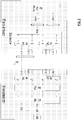
- FIG. 1 is an illustrative embodiment of a remote control system 100 in accordance with some embodiments of the present disclosure.
- the remote control system 100 includes a first computing device 101 coupled to a treatment system 110 and a second computing device 103.
- the second computing device 103 may include data processing components, such as processors (e.g., Embedded Technology eXtended (ETX), microblaze, etc.) and field-programmable gate arrays (FPGAs), on one or more printed circuit boards (PCBs) to communicate and/or manage the treatment system 110 via the first computing device 101.
- the first computing device 101 may also include FPGAs, some of which may be flash-based and less sensitive to neutrons, on one or more PCBs to interact with one or more components of the treatment system 110.
- the first computing device 101 and the treatment system 110 are located in a first environment 120, and the second computing device 103 is located in a second environment 130.
- the first environment 120 has a first neutron radiation level
- the second environment 130 has a second neutron radiation level.
- the first neutron radiation level is significantly higher than the second neutron radiation level
- the first environment 120 is in close proximity with the second environment 130 (e.g., less than 25 meters apart).
- the first environment 120 is also referred to as a treatment area/room, and the aforementioned PCBs inside the first environment 120 are also referred to as controller boards or controller PCBs.
- the second environment 130 is also referred to as a console area, and the aforementioned PCBs in the second environment 130 are also referred to as node carrier boards or node PCBs.
- a controller board may host a Mezzanine board to communicate with a node carrier board.
- a Mezzanine board usually has a smaller PCB footprint than a controller board.
- the first computing device 101 may be configured to transmit data collected by the treatment system 110 to the second computing device 103.
- the data may include radiation therapy data associated with the treatment system 110, such as, without limitation, position information, dosage information, and others.
- the second computing device 103 may be configured to issue and send a control command, such as a motor drive command, a dosage delivery command, or other commands, for the treatment system 110 to the first computing device 101.
- the first computing device 101 may be further configured to control the treatment system 110 according to the control command received from the second computing device 103.
- the first computing device 101 is configured to communicate with the second computing device 103 via a communication link 105.
- An example link may include, without limitation, a high speed serial bus.
- the communication infrastructure supported by the remote control system 100 provides at least the following capabilities: multiple Ethernet (or modified Ethernet protocol) links between the node and controller PCBs, a mirrored data transfer mode that includes time-critical and non-time-critical data transfer, watchdog, interrupt, interlock, and loop control.
- the first computing device 101 and the second computing device 103 may support at least two types of data transfer between them based on the priority of the data. Such data transfer is bidirectional, i.e., from the first computing device 101 to the second computing device 103 or from the second computing device 103 to the first computing device 101.
- non time-sensitive data may be transmitted with a lower priority.
- non time-sensitive data is stored in a set of predetermined registers/ports/memory areas. The set of predetermined registers/ports/memory areas are looped over repeatedly so that the data stored therein is being sent repeatedly as well.
- the data stored in this set of predetermined registers/ports/memory areas and sent in matter described above may also be referred to as "refresh data.”
- refresh data When a part of the non time-sensitive data fails to reach its destination because of a transmission error, the part of the non time-sensitive data may be resent later. Latency exists for the non time-sensitive data transmission because of the looping approach.
- Time-sensitive data may be transmitted with a higher priority.
- the address of a register/port/memory area which stores time-sensitive data may be written in a first-in, first-out (FIFO) manner.
- the first computing device 101 and the second computing device 103 may have their own FIFO buffers and may be configured to monitor the buffers. If an entry is found in a FIFO buffer at the first computing device 101, the first computing device 101 is configured to access time-sensitive data from the register/port pointed by the entry and transmit the time-sensitive data to the second computing device 103.
- the second computing device 103 is configured to access time-sensitive data from the register/port/memory area pointed to by the entry and transmit the time-sensitive data to the first computing device 101.
- time-sensitive data is transmitted once.
- time-sensitive data may be retransmitted if such time-sensitive data happens to be stored within the range of the set of predetermined registers/ports/memory area where non time-sensitive data is designated to be stored.
- the first computing device 101 and the second computing device 103 may each include a refresh watchdog, which may be configured to monitor the predetermined addresses associated with the register/port/memory area.
- the refresh watchdog times out, and the block of data stored in this set of predetermined addresses, including non time-sensitive data and time-sensitive data, may be transmitted (either from the first computing device 101 to the second computing device 103 or from the second computing device 103 to the first computing device 101).
- time-sensitive data may be retransmitted in response to a retransmission request from its destination if the destination does not receive expected time-sensitive data in time.
- the first computing device 101 and the second computing device 103 may each include one or more watchdogs other than the refresh watchdog discussed above. These watchdogs may be configured to look for certain expected information, such as, without limititation, interlock data, interrupt, time-sensitive data, and others, within a specified amount of time. When the watchdog times out and the expected information is not received, the first computing device 101 or the second computing device 103 may send a retransmission request to the other side.
- the first computing device 101 is configured to support a motor controlling board in a servomechanism (also referred to as a servo).
- Some example time-sensitive data may include position information (from the first computing device 101 to the second computing device 103) and motor drive commands (from the second computing device 103 to the first computing device 101).
- some example time-sensitive data may include measured dosage information (from the first computing device 101 to the second computing device 103) and dose delivery commands (from the second computing device 103 to the first computing device 101).
- a plurality of independent communication links are established between the first computing device 101 and the second computing device 103.
- a first link may have a mirrored architecture with a second link.
- any of the two sides of a link may be configured to operate on its own resources (e.g., memory space, registers, etc.)
- This architecture may also allow a large amount of data on both sides of a link to be transmitted bidirectionally, with each side of the link operating, for much of the data involved, independently.
- the second computing device 103 may be the master and may be configured to control the data transfer to and from the first computing device 101, the slave.
- the master may wait for two link times for the data to arrive, including the time to send a request to the slave first and and the time to wait for the data from the slave.
- FIG. 2 is a block diagram illustrating certain elements of a node carrier board 203 and a controller board 201 configured for a component of the treatment system 110 (e.g., the collimator) in accordance with some embodiments of the present disclosure.
- the controller board 201 may reside in the first computing device 101, and the node carrier board 203 may reside in the second computing device 103.
- the controller board 201 and the node carrier board are connected to a plurality of full duplex links, such as links 205.
- the links 205 may support the Ethernet protocol or a modified version of the protocol.
- the links 205 may also support mirrored data transfer capability.
- the controller board 201 includes a Mezzanine PCB 207, which includes logic to transmit and receive data to and from the node carrier board 203.
- the functionality supported by the Mezzanine PCB 207 may be implemented in the controller board 201.
- the controller board 201 includes a flash-based FPGA 209, which may be less sensitive to neutrons.
- the flash-based FPGA 209 may be configured to support triple modular redundancy (TMR), where storage registers in the FPGA may be tripled, and a voting system may be implemented to utilize the majority of the register states to generate an output, thereby being resistant to bit-flips. In other words, if any one of the three sets of register states fails, the other two sets may correct and mask the fault.
- TMR triple modular redundancy
- the flash-based FPGA 209 may also be configured to support at least interlock mechanisms (e.g., interlock controller(s) and registers), interrupt mechanisms (e.g., interrupt controller(s) and registers), watchdog timers, and error detection and/or correction mechanisms.
- interlock mechanisms e.g., interlock controller(s) and registers
- interrupt mechanisms e.g., interrupt controller(s) and registers
- watchdog timers e.g., interrupt controller(s) and registers
- error detection and/or correction mechanisms e.g., error detection and/or correction mechanisms.
- the node PCB 203 includes two FPGAs, 211 and 213. Each of these FPGAs, similar to the flash-based FPAG 209, may also be configured to support at least interlock mechanisms (e.g., interlock controller(s) and registers), interrupt mechanisms (e.g., interrupt controller(s) and registers), watchdog timers, and error detection and/or correction mechanisms. Additional details regarding the interlock mechanisms are further described in conjunction with FIG. 8 .
- interlock mechanisms e.g., interlock controller(s) and registers
- interrupt mechanisms e.g., interrupt controller(s) and registers
- watchdog timers e.g., error detection and/or correction mechanisms. Additional details regarding the interlock mechanisms are further described in conjunction with FIG. 8 .
- FIG. 3 is a block diagram illustrating certain elements of a node carrier board 303 and a controller board 301 configured for another component of the treatment system 110 (e.g., the Beam Generation and Monitoring (BGM) component) and the link to a sub-controller board 305 (e.g., the BGM-Positioning (BGM-POS) component for motor control of axes needed for generating beams) in accordance with some embodiments of the present disclosure.
- the flash-based FPGAs of the controller board 301 and the sub-controller board 305 may be configured to support the similar functions as the flash-based FPGA 209 of FIG. 2
- the FPGAs of the node carrier board 303 may be configured to support the similar function as the FPGAs 211 and 213 of FIG. 2 .
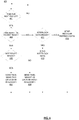
- FIGs 4 and 5 are flow charts of methods for operating a remote control system, such as the remote control system 100, from the perspective of a device including a controller board in accordance with some embodiments of the present disclosure.
- Method 400 may include one or more operations, functions or actions as illustrated by one or more of blocks 401, 403, 405, 407, 409, 411, 413, and/or 415.
- Method 500 may include one or more operations, functions or actions as illustrated by one or more blocks 501, 503, 505, and/or 507. The various blocks may be combined into fewer blocks, divided into additional blocks, and/or eliminated based upon the desired implementation.
- the controller board is configured to transmit information to a node carrier board and receive a command from the node carrier board.
- FIG. 4 is a flow chart of the method 400 from the transmission perspective of the device including the controller board, such as the first computing device 101 of FIG. 1 , the controller board 201 of FIG. 2 , or the controller board 301 of FIG. 3 .
- processing for method 400 may begin at block 401, "TIME FOR NEXT PACKET?"
- the first computing device 101 is configured to capture data collected by the treatment system 110, and in some embodiments, is configured to check periodically for this next packet of collected data. If it is time to transmit the next packet of collected data, block 401 may be followed by block 403, "TIME-SENSITIVE PACKET READY?”, where the first computing device 101 is configured to analyze the collected data such as whether the collected data may be time-sensitive.
- the controller board in the first computing device 101 may check its FIFO and service the data in the FIFO as time-sensitive data. If the time-sensitive packet is indeed ready, block 403 may be followed by block 405, "INTERRUPT READY?" If so, then block 405 may be followed by block 407, "SEND TIME-SENSITIVE DATA WITH INTERRUPT,” or otherwise followed by block 409, "SEND TIME-SENSITIVE DATA WITHOUT INTERRUPT.” In some embodiments, the first computing device 101 is configured to send such time-sensitive data to the second computing device 103 with a higher priority.
- block 403 may be followed by block 411, "INTERLOCK DATA READY?" If the interlock data is ready, then block 411 may be followed by block 413, "SEND INTERLOCK DATA.” Otherwise, block 411 may be followed by block 415, "SEND REGULAR REFRESH DATA.”
- the first computing device 101 may be configured to assert an interlock.
- the interlock data may be associated with time-sensitive data or non time-sensitive data and may be transmitted along with the collected data to the second computing device 103 for further processing.
- FIG. 5 is a flow chart of the method 500 from the receiving perspective of the device including the controller board, such as the first computing device 101 of FIG. 1 , the controller board 201 of FIG. 2 , or the controller board 301 of FIG. 3 .
- the first computing device 101 after transmitting the collected data and/or an interrupt to the second computing device 103, the first computing device 101 is configured to receive a command from the second computing device 103 in response to the collected data and/or the interrupt. Based on the received command, the first computing device 101 is configured to control the treatment system 110 accordingly.
- the first computing device 101 may be configured to control the treatment system 110 to perform one or more functions.
- the functions of the treatment system 110 may include power, axis movement, radiation beam configuration, and dosage measurement and delivery.
- the first computing device 101 After transmitting the collected data and/or an interlock to the second computing device 103, the first computing device 101 is configured to receive a command from the second computing device 103 to enable/disable a function of the treatment system 110. Processing for method 500 may begin at block 501, "PACKET RECEIVED?" If packet is indeed received, block 501 may be followed by block 503, "RE-REQUEST COMMAND?" If the received command is not a re-request command, then block 503 may be followed by block 507, "ACCEPT PACKET DATA.” For example, based on the received command, the first computing device 101 may be configured to enable or disable one of the power, axis movement, and radiation beam configuration functions of the treatment system 110.
- block 503 may be followed by block 505, "SETUP TIME-SENSITIVE TRANSMIT OF REQUESTED DATA," so that the data being re-requested may be sent as time-sensitive data and assigned a higher priority.
- watchdog mechanisms may be employed in the controller board of the first computing device 101.
- one watchdog mechanism for the controller board may be configured to check whether a command expected to be received from the second computing device 103 is indeed received within a certain amount of time. If the expected command is somehow not received, then the watchdog times out, and the controller board may be configured to send a time-sensitive message to the second computing device 103 with an interrupt to request for a resend of the command.
- FIGs 6 and 7 are flow charts of method for operating a remote control system, such as the remote control system 100, from the perspective of a device including a node carrier board in accordance with some embodiments of the present disclosure.
- Method 600 may include one or more operations, functions or actions as illustrated by one or more of blocks 601, 603, 605, and/or 607.
- Method 700 may include one or more operations, functions or actions as illustrated by one or more blocks 701, 703, 705, 707, 709, and/or 711.
- the various blocks may be combined into fewer blocks, divided into additional blocks, and/or eliminated based upon the desired implementation.
- the node carrier board is configured to issue a command to the controller board in response to the data collected by the node carrier board.
- FIG. 6 is a flow chart of method 600 from the transmission perspective of the device including the carrier board, such as second computing device 103 of FIG. 1 , the node carrier board 203 of FIG 2 , or the node carrier board 303 of FIG. 3 .
- processing for method 600 may begin at block 601, "TIME FOR NEXT PACKET?"
- the second computing device 103 may be configured to send commands to the first computing device 101.
- block 601 When it is time to send the next packet, block 601 may be followed by block 603, "TIME-SENSITIVE PACKET READY?" If the time-sensitive packet is ready to be sent, then block 603 may be followed by block 605, "SEND TIME-SENSITIVE DATA," where the data sent to the first computing device 101 is assigned a higher priority. On the other hand, if the time-sensitive packet is not ready to be sent, then block 603 may be followed by block 607, "SEND REGULAR REFRESH DATA.”
- FIG. 7 is a flow chart of method 700 from the receiving perspective of the device including the carrier board, such as second computing device 103 of FIG. 1 , the node carrier board 203 of FIG 2 , or the node carrier board 303 of FIG. 3 .
- processing for method 700 may begin at block 701, "PACKET RECEIVED?"
- the second computing device 103 may be configured to receive information from the first computing device 101.
- the information may include data collected from the treatment system 110, an interrupt asserted by the first computing device 101, or an interlock also asserted by the first computing device 101.
- block 701 may be followed by block 703, "INTERLOCK DATA?” If the received data is interlock data, then block 703 may be followed by block 705, "PRESENT INTERLOCK DATA TO INTERLOCK CONTROLLER," where the interlock controller of the second computing device 103 may be configured to process the interlock data. For example, the interlock controller may overwrite the asserted interlock under one set of settings or issue a command to enable/disable some functionalities of the treatment system 110 under another set of settings. In some embodiments, such a command to enable/disable functionalities of the treatment system 110 may be considered time-sensitive and may be sent with a high priority.
- block 703 may be followed by block 707, "INTERRUPT ASSERTED IN PACKET?" If an interrupted is asserted in the received packet, then block 707 may be followed by block 709, "ASSERT INTERRUPT,” where an interrupt may be asserted to a processor supported by the second computing device 103. Otherwise, block 707 may be followed by block 711, "ACCEPT PACKET DATA,” where the second computing device 103, in response to the received and accepted data that is not associated with the interrupt or the interlock, may be configured to transmit corresponding data back to the first computing device 101 with a non time-sensitive approach.
- watchdog mechanisms may be employed in the node carrier board of the second computing device 103.
- one watchdog mechanism for the node carrier board may be configured to monitor whether interlock data expected to be received from the first computing device 101 is indeed received within a certain amount of time. If the watchdog times out, then a latcher error condition may occur, which may cause the node carrier board to transition into a safe state.
- a pre-defined set of registers may be repeatedly looped, so that even if one packet is lost due to error, the packet may still reach its destination.
- the latency may correspond to the size of the data refresh area that the first computing device 101 and the second computing device 103 are configured to support.
- this data refresh area may be defined by setting the start address and the end address of a buffer area.
- time-sensitive registers may be memory mapped to a certain offset. Any register may be selected for time-sensitive data transfer even if it is outside or inside the data refresh area for the non time-sensitive data transfer. If there are more than two requestors for time-sensitive data transfer, an arbitration logic may be utilized.
- FIG. 8 is a block diagram illustrating one example interrupt flow in accordance with one embodiment of the present disclosure.
- interrupt capability may be supported by a controller board FPGA 801 and a sub-controller board FPGA 803 on a controller board and a node carrier board FPGA 805 on a node carrier board.
- Multiple interrupts may be shared by a mirror 1 controller, a mirror 2 controller, a processor 1, and a processor 2.
- the mirror 1 controller and/or the mirror 2 controller may interrupt the processor 1, the processor 2, and ETX of the node carrier board.
- the processor 1 or the processor 2 of the node carrier board may interrupt the ETX of the same node carrier board.
- interrupts may be transferred to the node carrier board from the controller board FPGA 801 and the sub-controller board FPGA 803 as numbers.
- the interrupts may also be sent during normal packets (e.g., occupying certain bits of the packets).
- limited interrupt information may be sent per packet (e.g., each packet may contain information associated with one interrupt).
- Some additional features of the interrupt capability may include, without limitation, 1) certain interrupt numbers may be pre-determined to be valid; 2) on the node carrier board, an interrupt bit corresponding to the interrupt number received may be set; 3) although it is not a requirement, a time-sensitive data transfer may be initiated and then the interrupt number may be provided on the read strobe (TX_MIRROR_RD_EN_COMB_OUT) of the critical cycle (TX_MIRROR_CRITICAL_CYCLE) by the FPGA logic at the same time the data is provided; 4) to address the possibility that interrupts may be missed on the node carrier board, the processor (e.g., ETX, microblaze, etc.) on the node carrier board may support a watchdog mechanism for interrupts that are raised from the controller board; 5) a built-in interrupt timer may be available for use per processor (e.g., microblaze) in the local register area associated with the processor.
- TX_MIRROR_RD_EN_COMB_OUT the critical cycle
- the processor e
- interrupt 0 may be raised by either the processor 1 or the processor 2.
- This interrupt may be shared with the interrupt timers (e.g., interrupt timer 1 and interrupt timer 2) associated with the processors, if such timers are enabled.
- the node board FPGA 805 may be configured to support an interlock controller (not shown in FIG. 8 ).
- interlock controller there may also be multiple interlock registers having multiple bits of interlock capability. There may be an override register associated with each of these interlock registers.
- Some of the interlock registers may be shared by the mirror 1 controller, mirror 2 controller, processor 1, and processor 2 of FIG. 8 .
- the other interlock registers may be shared by the processor 1 and processor 2 of the node carrier board.
- interlock registers may also be programmed to have impact on a motion enable loop (“MEL”), which enables the moving of any axis which could collide with a patient, a power enable loop (“PEL”), which enables power required to support system functions, such as moving axes or beam, a beam enable loop (“BEL”), which enables radiation to be delivered, or kilo-volt BEL (KVBEL), which also enables radiation to be delivered.
- MEL motion enable loop
- PEL power enable loop
- BEL beam enable loop
- KVBEL kilo-volt BEL
- these loops may correspond to physical current loops that are routed to most of the boards in a remote control system, such as the remote control system 100 of FIG. 1 . For each loop, current may be sent out from a source and may be routed through all controller boards and then back to the source.
- Any controller board in the path of the loop may be configured to open or close its control switch in series with the loop. If all the control switches in series with a loop are closed, then current is allowed to flow and this may enable a function. Conversely, if any controller board in series with the loop opens its control switch, then current flow is prevented, and a function may be disabled.
- the loop impact may be configured by the programming of the corresponding interlock register, such as the ILOCK_CONFIG register. For example, if bit 0 is set in an ILOCK_CONFIG register, that may be configured for PEL impact. If bit 1 is set in an ILOCK_CONFIG register, that may be configured for MEL impact. If bit 2 is set in an ILOCK_CONFIG register, that may be configured for BEL impact. If bit 3 is set in an ILOCK_CONFIG register, that may be configured for KVBEL impact.
- the interlock controller may be configured to monitor interlock sources and latch them until the processor of the node carrier board, such as the ETX, clears them. Any asserted interlock in a loop's register may result in an open loop if interlock is not overridden.
- the node carrier board sometimes may override the interlock for debugging purposes.
- the controller board may be configured to assert the interlock that is dedicated to this particular feedback encoder and send the interlock in a special time-sensitive message to a node carrier board in the computing device 103.
- the interlock controller of the node carrier board would see the interlock data (e.g., by inspecting interlock registers) and inspect state information associated with the PEL, BEL, MEL, and KVBEL (e.g., the configuration bits). Given that this example is related to motion, the MEL bit would be set.
- the node carrier board may be configured to send a MEL open control bit to the controller board, if the node carrier board has not overridden the interlock.
- the controller board may be configured to open the MEL loop and thus disable motion on the treatment system 110 to prevent the failed feedback encoder from introducing improper motion.
- the communication control logic in the controller board may send interlock information from 4 interlock registers over 8 packets.
- the interlock information may be sent in the data field while sending time-sensitive packets with specific address.
- the common control logic may increment the two bit interlock counter for that interlock by one (if previous interlock was already sent to the node carrier board) and wait for the turn to send interlock packet.
- the two-bit interlock counter may also help with mirrored architecture of the link and any missed interlock packet data. If any interlock packet was discarded due to error, the same information may be sent on the next available interlock packet.
- the communication control logic may provide an option to specify time between transmissions of interlock data.
- the communication control logic may also provide generics for the controller board to indicate how many of the interlocks are being used. For example, a value of 0 may mean that interlock data is not sent to the node carrier board (two interlock packets are not sent). A value of less than 16 (interlock data in lower 16 bits of the register) may result in savings of one interlock packet. Lesser the number of interlock packets, better bandwidth utilization of the link (the time can be used for sending other packets).
- an interlock may be accepted if the two-bit counter value is different from existing counter value. Otherwise, no interlock may be raised.
- the node carrier board FPGA 805 may be configured to support enable loop control logic, so that all of the aforementioned loops, PEL, BEL, MEL, and KVBEL, may be controlled by the node carrier board FPGA 805.
- the loop control logic may be configured to open the corresponding loop if any of the following conditions are met subject to the settings of the LOOP_IMPACT register of the other link: a) corresponding interlock is asserted, b) ETX loop control bit not set, c) processor 1 loop control bit not set, d) processor 2 loop control bit not set, e) communication error is asserted by Mirror 1 (Link 1), f) communication error is asserted by Mirror 2 (Link 2), g) ETX Watchdog timed-out, h) Processor 1 Watchdog timed-out, and g) Processor 2 Watchdog timed-out.
- PEL_CTRL, MEL_CTRL, BEL_CTRL and KVBEL_CTRL signals may be available from the common control logic to control the loops. These signals may be qualified with error signals on the controller board.
- the mirror 1 controller and mirror 2 controller may provide status of the loops back to the common control logic in the following ports - PEL_STAT, MEL_STAT, BEL_STAT and KVBEL_STAT.
- multiple watchdog mechanisms may be supported by the controller board and the node carrier board.
- Some example watchdog mechanisms supported on the node carrier board include, without limitation, a Peripheral Component Interconnect (PCI) watchdog, a processor (e.g., microblaze) watchdog, a node refresh watchdog, and a node interlock refresh watchdog.
- the PCI watchdog may be for the ETX of the node carrier board and may be hit within 22 mS.
- the microblaze watchdog may be hit within 1 mS.
- the node refresh watchdog may be configured to monitor the update times for the data sent from the controller board to the node carrier board.
- the address area to monitor and the timeout value may be programmed through register RX_CHECK_CONFIG.
- the node interlock refresh watchdog may be configured to monitor the update times for interlock data sent from the controller board to the node carrier board.
- Some example watchdog mechanisms supported on the controller board include a controller refresh watchdog, which may be configured to monitor the update times for the data sent from the node carrier board to the controller board.
Landscapes
- Health & Medical Sciences (AREA)
- Engineering & Computer Science (AREA)
- Biomedical Technology (AREA)
- General Health & Medical Sciences (AREA)
- Nuclear Medicine, Radiotherapy & Molecular Imaging (AREA)
- Public Health (AREA)
- Radiology & Medical Imaging (AREA)
- Pathology (AREA)
- Life Sciences & Earth Sciences (AREA)
- Animal Behavior & Ethology (AREA)
- Veterinary Medicine (AREA)
- Medical Informatics (AREA)
- Primary Health Care (AREA)
- Epidemiology (AREA)
- Urology & Nephrology (AREA)
- Surgery (AREA)
- Radiation-Therapy Devices (AREA)
- Debugging And Monitoring (AREA)
Claims (15)
- System, das dazu ausgelegt ist, Kommunikation zwischen einer ersten Umgebung mit einem ersten Neutronenstrahlungspegel und einer zweiten Umgebung mit einem zweiten Neutronenstrahlungspegel, der sich von dem ersten Neutronenstrahlungspegel unterscheidet, zu unterstützen, umfassend:eine erste Rechenvorrichtung (101), die dazu ausgelegt ist, ein Behandlungssystem (110) in der ersten Umgebung (120) zu steuern; undeine zweite Rechenvorrichtung (103), die dazu ausgelegt ist, einen Befehl in der zweiten Umgebung (130) für das Behandlungssystem (110) auszugeben, wobeidie erste Rechenvorrichtung (101) ferner dazu ausgelegt ist,zu bestimmen, ob eine vom Behandlungssystem (110) unterstützte Funktion aktiviert oder deaktiviert werden soll,wenn zu übertragende ausstehende zeitkritische Daten vorliegen, die ausstehenden zeitkritischen Daten mit einer höheren Priorität als nicht zeitkritische Daten zu übertragen undperiodisch in der ersten Umgebung (120) erfasste erste Strahlentherapiedaten und einen ersten Interrupt an die zweite Rechenvorrichtung (103) in einem Hilfsregelkreis zu übertragen; dadurch gekennzeichnet, dassdie erste Rechenvorrichtung (101) ferner dazu ausgelegt ist, eine Neuübertragungsanforderung von der zweiten Rechenvorrichtung (103) zu empfangen, wenn die zweite Rechenvorrichtung (103) keine erwarteten Informationen innerhalb einer bestimmten Zeit empfängt.
- System nach Anspruch 1, wobei die erste Rechenvorrichtung (101) ferner dazu ausgelegt ist, zweite in der ersten Umgebung (120) erfasste Strahlentherapiedaten und einen ersten Interlock an die zweite Rechenvorrichtung (103) zu übertragen.
- System nach Anspruch 1, wobei die erste Rechenvorrichtung (101) ferner dazu ausgelegt ist, zu bestimmen, ob Interlock-Daten an die zweite Rechenvorrichtung (103) übertragen werden sollen.
- System nach Anspruch 1, wobei die erste Rechenvorrichtung (101) ferner dazu ausgelegt ist, die ersten Strahlentherapiedaten und den ersten Interrupt in einem zeitkritischen Paket vor Übertragen des Pakets zu platzieren.
- System nach Anspruch 3, wobei die erste Rechenvorrichtung (101) ferner dazu ausgelegt ist, die Funktion auf Grundlage eines von der zweiten Rechenvorrichtung empfangenen Steuerungszustands einer Aktivierungsschleife zu aktivieren oder deaktivieren.
- System nach Anspruch 1, wobei:die erste Rechenvorrichtung (101) ferner dazu ausgelegt ist, ein zeitkritisches Paket mit einem Interrupt zu senden, um ein erneutes Senden des Befehls anzufordern, wenn die erste Rechenvorrichtung (101) den Befehl nicht innerhalb eines vorgegebenen Zeitraums empfängt; und/oderdie erste Rechenvorrichtung (101) ferner dazu ausgelegt ist, die ersten Strahlentherapiedaten von einem ersten vorgegebenen Satz von Adressen, der zum Speichern von zeitkritischen Daten vorgesehen ist, abzurufen.
- System nach Anspruch 1, wobei die erste Rechenvorrichtung (101) ferner dazu ausgelegt ist, eine Neuübertragungsanforderung von der zweiten Rechenvorrichtung (103) zu empfangen, wenn die zweite Rechenvorrichtung (103) die ausstehenden zeitkritischen Daten oder den ersten Interrupt nicht innerhalb einer bestimmten Zeit empfängt.
- System, das dazu ausgelegt ist, Kommunikation zwischen einer ersten Umgebung mit einem ersten Neutronenstrahlungspegel und einer zweiten Umgebung mit einem zweiten Neutronenstrahlungspegel, der sich von dem ersten Neutronenstrahlungspegel unterscheidet, zu unterstützen, umfassend:eine erste Rechenvorrichtung (101), die dazu ausgelegt ist, ein Behandlungssystem (110) in der ersten Umgebung (120) zu steuern; undeine zweite Rechenvorrichtung (103), die dazu ausgelegt ist, Befehle in der zweiten Umgebung (130) für das Behandlungssystem (110) auszugeben, wobeidie zweite Rechenvorrichtung (103) ferner dazu ausgelegt ist,zu bestimmen, ob ein erster Befehl an die erste Rechenvorrichtung (101) ausgegeben werden soll, um eine erste vom Behandlungssystem (110) unterstützte Funktion zu aktivieren oder zu deaktivieren,wenn zu übertragende ausstehende zeitkritische Daten vorliegen, die ausstehenden zeitkritischen Daten mit einer höheren Priorität als nicht zeitkritische Daten zu übertragen undeine Funktion in Reaktion auf einen ersten Interrupt, der von der ersten Rechenvorrichtung (101) gesendet wird, und auf Grundlage von Strahlentherapiedaten von der ersten Rechenvorrichtung (101) durchzuführen, dadurch gekennzeichnet, dassdie zweite Rechenvorrichtung (103) ferner dazu ausgelegt ist, eine Neuübertragungsanforderung von der ersten Rechenvorrichtung (101) zu empfangen, wenn die erste Rechenvorrichtung (101) keine erwarteten Informationen innerhalb einer bestimmten Zeit empfängt.
- System nach Anspruch 8, wobei die zweite Rechenvorrichtung (103) ferner dazu ausgelegt ist, auf Grundlage davon, ob Interlock-Daten von der ersten Rechenvorrichtung (101) innerhalb eines vorgegebenen Zeitraums empfangen werden, zu bestimmen, ob der erste Befehl ausgegeben werden soll.
- System nach Anspruch 9, wobei die zweite Rechenvorrichtung (103) ferner dazu ausgelegt ist, ein vorgegebenes Register auf die Interlock-Daten zu prüfen, um zu bestimmen, ob die Interlock-Daten empfangen wurden.
- System nach Anspruch 8, wobei:die zweite Rechenvorrichtung (103) ferner dazu ausgelegt ist, in einen sicheren Zustand überzugehen, nachdem die zweite Rechenvorrichtung (103) die Interlock-Daten nicht innerhalb eines vorgegebenen Zeitraums empfangen hat; und/oderdie zweite Rechenvorrichtung (103) ferner dazu ausgelegt ist, die zeitkritischen Daten von einem ersten vorgegebenen Satz von Adressen abzurufen.
- System nach Anspruch 1 oder 8, wobei sich die erste Umgebung (120) in großer Nähe zu der zweiten Umgebung (130) befindet.
- System nach Anspruch 1 oder 8, wobei eine gespiegelte Architektur zwischen der ersten Rechenvorrichtung (101) und der zweiten Rechenvorrichtung (103) unterstützt wird.
- System nach Anspruch 13, wobei eine aus der ersten und zweiten Rechenvorrichtung (101, 103) ferner dazu ausgelegt ist, periodisch Daten, die in einem zweiten vorgegebenen Satz von Adressen gespeichert sind, der zum Speichern von sowohl nicht zeitkritischen Daten als auch zeitkritischen Daten vorgesehen ist, an die andere aus der ersten und zweiten Rechenvorrichtung (101, 103) zu übertragen.
- System nach Anspruch 8, wobei die zweite Rechenvorrichtung (103) ferner dazu ausgelegt ist, eine Neuübertragungsanforderung von der ersten Rechenvorrichtung (101) zu empfangen, wenn die erste Rechenvorrichtung (101) die ausstehenden zeitkritischen Daten oder den ersten Interrupt nicht innerhalb einer bestimmten Zeit empfängt.
Applications Claiming Priority (2)
| Application Number | Priority Date | Filing Date | Title |
|---|---|---|---|
| US201261590784P | 2012-01-25 | 2012-01-25 | |
| PCT/US2013/023318 WO2013112954A1 (en) | 2012-01-25 | 2013-01-25 | Remote control system and method |
Publications (3)
| Publication Number | Publication Date |
|---|---|
| EP2806786A1 EP2806786A1 (de) | 2014-12-03 |
| EP2806786A4 EP2806786A4 (de) | 2016-05-18 |
| EP2806786B1 true EP2806786B1 (de) | 2018-05-09 |
Family
ID=48873983
Family Applications (1)
| Application Number | Title | Priority Date | Filing Date |
|---|---|---|---|
| EP13741526.1A Active EP2806786B1 (de) | 2012-01-25 | 2013-01-25 | Fernsteuerungssystem und -verfahren |
Country Status (4)
| Country | Link |
|---|---|
| US (1) | US9956430B2 (de) |
| EP (1) | EP2806786B1 (de) |
| CN (1) | CN104066480B (de) |
| WO (1) | WO2013112954A1 (de) |
Families Citing this family (3)
| Publication number | Priority date | Publication date | Assignee | Title |
|---|---|---|---|---|
| CN111282153A (zh) * | 2018-12-07 | 2020-06-16 | 拉菲尔股份有限公司 | 电刺激装置及电刺激系统 |
| DE102019201096A1 (de) * | 2019-01-29 | 2020-07-30 | Robert Bosch Gmbh | Integrierter Schaltkreis und eingebettetes System mit einem solchen integrierten Schaltkreis |
| US20260061220A1 (en) * | 2024-08-27 | 2026-03-05 | Varian Medical Systems, Inc. | Systems, apparatuses, and methods for radiation therapy |
Family Cites Families (9)
| Publication number | Priority date | Publication date | Assignee | Title |
|---|---|---|---|---|
| DE3788721T2 (de) * | 1986-10-17 | 1994-06-09 | Fujitsu Ltd | Datenübertragungssystem mit übertragunsdiskriminierungsschaltung. |
| JP3442932B2 (ja) | 1995-09-29 | 2003-09-02 | インターナショナル・ビジネス・マシーンズ・コーポレーション | 情報処理システム |
| US6118847A (en) * | 1998-01-15 | 2000-09-12 | Siemens Medical Systems, Inc. | System and method for gated radiotherapy based on physiological inputs |
| CA2524029A1 (en) * | 2003-04-30 | 2004-11-18 | Insulet Corporation | Rf medical device |
| US20070104316A1 (en) * | 2005-07-22 | 2007-05-10 | Ruchala Kenneth J | System and method of recommending a location for radiation therapy treatment |
| US7680880B2 (en) * | 2006-04-25 | 2010-03-16 | Mcafee, Inc. | System and method for protecting a computer network |
| DE102006058359A1 (de) * | 2006-12-05 | 2008-06-12 | Carl Zeiss Surgical Gmbh | Fernsteuerungssystem für medizinische Geräte |
| US20080021741A1 (en) * | 2006-07-19 | 2008-01-24 | Mdatalink, Llc | System For Remote Review Of Clinical Data |
| US7978062B2 (en) * | 2007-08-31 | 2011-07-12 | Cardiac Pacemakers, Inc. | Medical data transport over wireless life critical network |
-
2013
- 2013-01-25 CN CN201380006527.9A patent/CN104066480B/zh active Active
- 2013-01-25 US US14/373,036 patent/US9956430B2/en active Active
- 2013-01-25 EP EP13741526.1A patent/EP2806786B1/de active Active
- 2013-01-25 WO PCT/US2013/023318 patent/WO2013112954A1/en not_active Ceased
Non-Patent Citations (1)
| Title |
|---|
| None * |
Also Published As
| Publication number | Publication date |
|---|---|
| CN104066480A (zh) | 2014-09-24 |
| EP2806786A1 (de) | 2014-12-03 |
| US9956430B2 (en) | 2018-05-01 |
| EP2806786A4 (de) | 2016-05-18 |
| CN104066480B (zh) | 2017-04-05 |
| US20140371512A1 (en) | 2014-12-18 |
| WO2013112954A1 (en) | 2013-08-01 |
Similar Documents
| Publication | Publication Date | Title |
|---|---|---|
| US11989154B2 (en) | Hybrid remote direct memory access | |
| US11088782B2 (en) | Use of a cyclic redundancy code multiple-input shift register to provide early warning and fail detection | |
| US8458267B2 (en) | Distributed parallel messaging for multiprocessor systems | |
| EP1374521B1 (de) | Verfahren und vorrichtung zur fernprüfung von schlüsseln für ngio/infiniband anwendungen | |
| CN105117299B (zh) | 用于进行超时监测的方法和系统 | |
| US20140068134A1 (en) | Data transmission apparatus, system, and method | |
| US9575825B2 (en) | Push instruction for pushing a message payload from a sending thread to a receiving thread | |
| CN101506783B (zh) | 用于阻隔操作的条件式广播的方法和设备 | |
| US8151026B2 (en) | Method and system for secure communication between processor partitions | |
| CN114026829A (zh) | 同步网络 | |
| EP2548127B1 (de) | Abarbeiten von busanforderungen und daten in einer busarchitektur | |
| US20080147822A1 (en) | Systems, methods and computer program products for automatically triggering operations on a queue pair | |
| US20250355666A1 (en) | Detecting infinite loops in a programmable atomic transaction | |
| EP2806786B1 (de) | Fernsteuerungssystem und -verfahren | |
| US8086766B2 (en) | Support for non-locking parallel reception of packets belonging to a single memory reception FIFO | |
| US20110320743A1 (en) | Memory ordered store system in a multiprocessor computer system | |
| US9678812B2 (en) | Addressing for inter-thread push communication | |
| US10505704B1 (en) | Data uploading to asynchronous circuitry using circular buffer control | |
| US9778933B2 (en) | Non-serialized push instruction for pushing a message payload from a sending thread to a receiving thread | |
| US7523351B2 (en) | System and method for providing mutual breakpoint capabilities in computing device | |
| KR20210113560A (ko) | 타겟 장치에 의한 명령어 실행 순서를 제어하는 시스템 및 방법 | |
| EP1069734B1 (de) | Verteilter Bus für Dienstanforderungen mit Token zur Auflösung von Kollisionen | |
| Hoyme et al. | SAFEbus (for avionics) | |
| HK1150084B (en) | Delegating network processor operations to star topology serial bus interfaces |
Legal Events
| Date | Code | Title | Description |
|---|---|---|---|
| PUAI | Public reference made under article 153(3) epc to a published international application that has entered the european phase |
Free format text: ORIGINAL CODE: 0009012 |
|
| 17P | Request for examination filed |
Effective date: 20140728 |
|
| AK | Designated contracting states |
Kind code of ref document: A1 Designated state(s): AL AT BE BG CH CY CZ DE DK EE ES FI FR GB GR HR HU IE IS IT LI LT LU LV MC MK MT NL NO PL PT RO RS SE SI SK SM TR |
|
| DAX | Request for extension of the european patent (deleted) | ||
| RA4 | Supplementary search report drawn up and despatched (corrected) |
Effective date: 20160414 |
|
| RIC1 | Information provided on ipc code assigned before grant |
Ipc: A61N 5/10 20060101ALI20160408BHEP Ipc: G06F 19/00 20110101ALI20160408BHEP Ipc: A61B 5/00 20060101AFI20160408BHEP Ipc: A61B 6/00 20060101ALI20160408BHEP |
|
| GRAP | Despatch of communication of intention to grant a patent |
Free format text: ORIGINAL CODE: EPIDOSNIGR1 |
|
| STAA | Information on the status of an ep patent application or granted ep patent |
Free format text: STATUS: GRANT OF PATENT IS INTENDED |
|
| INTG | Intention to grant announced |
Effective date: 20171129 |
|
| RIN1 | Information on inventor provided before grant (corrected) |
Inventor name: GREENBERG, KEVIN Inventor name: DALLA RICCA, PAOLO |
|
| GRAS | Grant fee paid |
Free format text: ORIGINAL CODE: EPIDOSNIGR3 |
|
| GRAA | (expected) grant |
Free format text: ORIGINAL CODE: 0009210 |
|
| STAA | Information on the status of an ep patent application or granted ep patent |
Free format text: STATUS: THE PATENT HAS BEEN GRANTED |
|
| AK | Designated contracting states |
Kind code of ref document: B1 Designated state(s): AL AT BE BG CH CY CZ DE DK EE ES FI FR GB GR HR HU IE IS IT LI LT LU LV MC MK MT NL NO PL PT RO RS SE SI SK SM TR |
|
| REG | Reference to a national code |
Ref country code: GB Ref legal event code: FG4D |
|
| REG | Reference to a national code |
Ref country code: CH Ref legal event code: EP Ref country code: AT Ref legal event code: REF Ref document number: 996769 Country of ref document: AT Kind code of ref document: T Effective date: 20180515 |
|
| REG | Reference to a national code |
Ref country code: IE Ref legal event code: FG4D |
|
| REG | Reference to a national code |
Ref country code: DE Ref legal event code: R096 Ref document number: 602013037230 Country of ref document: DE |
|
| REG | Reference to a national code |
Ref country code: DE Ref legal event code: R082 Ref document number: 602013037230 Country of ref document: DE Representative=s name: LORENZ SEIDLER GOSSEL RECHTSANWAELTE PATENTANW, DE |
|
| REG | Reference to a national code |
Ref country code: NL Ref legal event code: MP Effective date: 20180509 |
|
| REG | Reference to a national code |
Ref country code: LT Ref legal event code: MG4D |
|
| PG25 | Lapsed in a contracting state [announced via postgrant information from national office to epo] |
Ref country code: BG Free format text: LAPSE BECAUSE OF FAILURE TO SUBMIT A TRANSLATION OF THE DESCRIPTION OR TO PAY THE FEE WITHIN THE PRESCRIBED TIME-LIMIT Effective date: 20180809 Ref country code: FI Free format text: LAPSE BECAUSE OF FAILURE TO SUBMIT A TRANSLATION OF THE DESCRIPTION OR TO PAY THE FEE WITHIN THE PRESCRIBED TIME-LIMIT Effective date: 20180509 Ref country code: NO Free format text: LAPSE BECAUSE OF FAILURE TO SUBMIT A TRANSLATION OF THE DESCRIPTION OR TO PAY THE FEE WITHIN THE PRESCRIBED TIME-LIMIT Effective date: 20180809 Ref country code: ES Free format text: LAPSE BECAUSE OF FAILURE TO SUBMIT A TRANSLATION OF THE DESCRIPTION OR TO PAY THE FEE WITHIN THE PRESCRIBED TIME-LIMIT Effective date: 20180509 Ref country code: SE Free format text: LAPSE BECAUSE OF FAILURE TO SUBMIT A TRANSLATION OF THE DESCRIPTION OR TO PAY THE FEE WITHIN THE PRESCRIBED TIME-LIMIT Effective date: 20180509 Ref country code: LT Free format text: LAPSE BECAUSE OF FAILURE TO SUBMIT A TRANSLATION OF THE DESCRIPTION OR TO PAY THE FEE WITHIN THE PRESCRIBED TIME-LIMIT Effective date: 20180509 |
|
| PG25 | Lapsed in a contracting state [announced via postgrant information from national office to epo] |
Ref country code: LV Free format text: LAPSE BECAUSE OF FAILURE TO SUBMIT A TRANSLATION OF THE DESCRIPTION OR TO PAY THE FEE WITHIN THE PRESCRIBED TIME-LIMIT Effective date: 20180509 Ref country code: RS Free format text: LAPSE BECAUSE OF FAILURE TO SUBMIT A TRANSLATION OF THE DESCRIPTION OR TO PAY THE FEE WITHIN THE PRESCRIBED TIME-LIMIT Effective date: 20180509 Ref country code: NL Free format text: LAPSE BECAUSE OF FAILURE TO SUBMIT A TRANSLATION OF THE DESCRIPTION OR TO PAY THE FEE WITHIN THE PRESCRIBED TIME-LIMIT Effective date: 20180509 Ref country code: HR Free format text: LAPSE BECAUSE OF FAILURE TO SUBMIT A TRANSLATION OF THE DESCRIPTION OR TO PAY THE FEE WITHIN THE PRESCRIBED TIME-LIMIT Effective date: 20180509 Ref country code: GR Free format text: LAPSE BECAUSE OF FAILURE TO SUBMIT A TRANSLATION OF THE DESCRIPTION OR TO PAY THE FEE WITHIN THE PRESCRIBED TIME-LIMIT Effective date: 20180810 |
|
| REG | Reference to a national code |
Ref country code: AT Ref legal event code: MK05 Ref document number: 996769 Country of ref document: AT Kind code of ref document: T Effective date: 20180509 |
|
| PG25 | Lapsed in a contracting state [announced via postgrant information from national office to epo] |
Ref country code: EE Free format text: LAPSE BECAUSE OF FAILURE TO SUBMIT A TRANSLATION OF THE DESCRIPTION OR TO PAY THE FEE WITHIN THE PRESCRIBED TIME-LIMIT Effective date: 20180509 Ref country code: PL Free format text: LAPSE BECAUSE OF FAILURE TO SUBMIT A TRANSLATION OF THE DESCRIPTION OR TO PAY THE FEE WITHIN THE PRESCRIBED TIME-LIMIT Effective date: 20180509 Ref country code: AT Free format text: LAPSE BECAUSE OF FAILURE TO SUBMIT A TRANSLATION OF THE DESCRIPTION OR TO PAY THE FEE WITHIN THE PRESCRIBED TIME-LIMIT Effective date: 20180509 Ref country code: RO Free format text: LAPSE BECAUSE OF FAILURE TO SUBMIT A TRANSLATION OF THE DESCRIPTION OR TO PAY THE FEE WITHIN THE PRESCRIBED TIME-LIMIT Effective date: 20180509 Ref country code: CZ Free format text: LAPSE BECAUSE OF FAILURE TO SUBMIT A TRANSLATION OF THE DESCRIPTION OR TO PAY THE FEE WITHIN THE PRESCRIBED TIME-LIMIT Effective date: 20180509 Ref country code: SK Free format text: LAPSE BECAUSE OF FAILURE TO SUBMIT A TRANSLATION OF THE DESCRIPTION OR TO PAY THE FEE WITHIN THE PRESCRIBED TIME-LIMIT Effective date: 20180509 Ref country code: DK Free format text: LAPSE BECAUSE OF FAILURE TO SUBMIT A TRANSLATION OF THE DESCRIPTION OR TO PAY THE FEE WITHIN THE PRESCRIBED TIME-LIMIT Effective date: 20180509 |
|
| REG | Reference to a national code |
Ref country code: DE Ref legal event code: R097 Ref document number: 602013037230 Country of ref document: DE |
|
| PG25 | Lapsed in a contracting state [announced via postgrant information from national office to epo] |
Ref country code: SM Free format text: LAPSE BECAUSE OF FAILURE TO SUBMIT A TRANSLATION OF THE DESCRIPTION OR TO PAY THE FEE WITHIN THE PRESCRIBED TIME-LIMIT Effective date: 20180509 Ref country code: IT Free format text: LAPSE BECAUSE OF FAILURE TO SUBMIT A TRANSLATION OF THE DESCRIPTION OR TO PAY THE FEE WITHIN THE PRESCRIBED TIME-LIMIT Effective date: 20180509 |
|
| PLBE | No opposition filed within time limit |
Free format text: ORIGINAL CODE: 0009261 |
|
| STAA | Information on the status of an ep patent application or granted ep patent |
Free format text: STATUS: NO OPPOSITION FILED WITHIN TIME LIMIT |
|
| 26N | No opposition filed |
Effective date: 20190212 |
|
| PG25 | Lapsed in a contracting state [announced via postgrant information from national office to epo] |
Ref country code: SI Free format text: LAPSE BECAUSE OF FAILURE TO SUBMIT A TRANSLATION OF THE DESCRIPTION OR TO PAY THE FEE WITHIN THE PRESCRIBED TIME-LIMIT Effective date: 20180509 |
|
| PG25 | Lapsed in a contracting state [announced via postgrant information from national office to epo] |
Ref country code: MC Free format text: LAPSE BECAUSE OF FAILURE TO SUBMIT A TRANSLATION OF THE DESCRIPTION OR TO PAY THE FEE WITHIN THE PRESCRIBED TIME-LIMIT Effective date: 20180509 |
|
| REG | Reference to a national code |
Ref country code: CH Ref legal event code: PL |
|
| PG25 | Lapsed in a contracting state [announced via postgrant information from national office to epo] |
Ref country code: LU Free format text: LAPSE BECAUSE OF NON-PAYMENT OF DUE FEES Effective date: 20190125 |
|
| REG | Reference to a national code |
Ref country code: BE Ref legal event code: MM Effective date: 20190131 |
|
| REG | Reference to a national code |
Ref country code: IE Ref legal event code: MM4A |
|
| PG25 | Lapsed in a contracting state [announced via postgrant information from national office to epo] |
Ref country code: FR Free format text: LAPSE BECAUSE OF NON-PAYMENT OF DUE FEES Effective date: 20190131 |
|
| PG25 | Lapsed in a contracting state [announced via postgrant information from national office to epo] |
Ref country code: AL Free format text: LAPSE BECAUSE OF FAILURE TO SUBMIT A TRANSLATION OF THE DESCRIPTION OR TO PAY THE FEE WITHIN THE PRESCRIBED TIME-LIMIT Effective date: 20180509 Ref country code: BE Free format text: LAPSE BECAUSE OF NON-PAYMENT OF DUE FEES Effective date: 20190131 |
|
| PG25 | Lapsed in a contracting state [announced via postgrant information from national office to epo] |
Ref country code: LI Free format text: LAPSE BECAUSE OF NON-PAYMENT OF DUE FEES Effective date: 20190131 Ref country code: CH Free format text: LAPSE BECAUSE OF NON-PAYMENT OF DUE FEES Effective date: 20190131 |
|
| PG25 | Lapsed in a contracting state [announced via postgrant information from national office to epo] |
Ref country code: IE Free format text: LAPSE BECAUSE OF NON-PAYMENT OF DUE FEES Effective date: 20190125 |
|
| PG25 | Lapsed in a contracting state [announced via postgrant information from national office to epo] |
Ref country code: TR Free format text: LAPSE BECAUSE OF FAILURE TO SUBMIT A TRANSLATION OF THE DESCRIPTION OR TO PAY THE FEE WITHIN THE PRESCRIBED TIME-LIMIT Effective date: 20180509 |
|
| PG25 | Lapsed in a contracting state [announced via postgrant information from national office to epo] |
Ref country code: MT Free format text: LAPSE BECAUSE OF NON-PAYMENT OF DUE FEES Effective date: 20190125 Ref country code: PT Free format text: LAPSE BECAUSE OF FAILURE TO SUBMIT A TRANSLATION OF THE DESCRIPTION OR TO PAY THE FEE WITHIN THE PRESCRIBED TIME-LIMIT Effective date: 20180910 |
|
| PG25 | Lapsed in a contracting state [announced via postgrant information from national office to epo] |
Ref country code: CY Free format text: LAPSE BECAUSE OF FAILURE TO SUBMIT A TRANSLATION OF THE DESCRIPTION OR TO PAY THE FEE WITHIN THE PRESCRIBED TIME-LIMIT Effective date: 20180509 |
|
| PG25 | Lapsed in a contracting state [announced via postgrant information from national office to epo] |
Ref country code: IS Free format text: LAPSE BECAUSE OF FAILURE TO SUBMIT A TRANSLATION OF THE DESCRIPTION OR TO PAY THE FEE WITHIN THE PRESCRIBED TIME-LIMIT Effective date: 20180909 |
|
| PG25 | Lapsed in a contracting state [announced via postgrant information from national office to epo] |
Ref country code: HU Free format text: LAPSE BECAUSE OF FAILURE TO SUBMIT A TRANSLATION OF THE DESCRIPTION OR TO PAY THE FEE WITHIN THE PRESCRIBED TIME-LIMIT; INVALID AB INITIO Effective date: 20130125 |
|
| PG25 | Lapsed in a contracting state [announced via postgrant information from national office to epo] |
Ref country code: MK Free format text: LAPSE BECAUSE OF FAILURE TO SUBMIT A TRANSLATION OF THE DESCRIPTION OR TO PAY THE FEE WITHIN THE PRESCRIBED TIME-LIMIT Effective date: 20180509 |
|
| PGFP | Annual fee paid to national office [announced via postgrant information from national office to epo] |
Ref country code: GB Payment date: 20260210 Year of fee payment: 14 |
|
| PGFP | Annual fee paid to national office [announced via postgrant information from national office to epo] |
Ref country code: DE Payment date: 20260320 Year of fee payment: 14 |