EP2806571A1 - Verfahren und Zugangsknoten zum Verbinden von Teilnehmeranschlüssen - Google Patents
Verfahren und Zugangsknoten zum Verbinden von Teilnehmeranschlüssen Download PDFInfo
- Publication number
- EP2806571A1 EP2806571A1 EP13305667.1A EP13305667A EP2806571A1 EP 2806571 A1 EP2806571 A1 EP 2806571A1 EP 13305667 A EP13305667 A EP 13305667A EP 2806571 A1 EP2806571 A1 EP 2806571A1
- Authority
- EP
- European Patent Office
- Prior art keywords
- subscriber line
- assigned
- unassigned
- lines
- subscriber
- Prior art date
- Legal status (The legal status is an assumption and is not a legal conclusion. Google has not performed a legal analysis and makes no representation as to the accuracy of the status listed.)
- Withdrawn
Links
Images



Classifications
-
- H—ELECTRICITY
- H04—ELECTRIC COMMUNICATION TECHNIQUE
- H04B—TRANSMISSION
- H04B3/00—Line transmission systems
- H04B3/02—Details
- H04B3/46—Monitoring; Testing
- H04B3/487—Testing crosstalk effects
-
- H—ELECTRICITY
- H04—ELECTRIC COMMUNICATION TECHNIQUE
- H04L—TRANSMISSION OF DIGITAL INFORMATION, e.g. TELEGRAPHIC COMMUNICATION
- H04L5/00—Arrangements affording multiple use of the transmission path
- H04L5/0001—Arrangements for dividing the transmission path
- H04L5/0014—Three-dimensional division
- H04L5/0023—Time-frequency-space
-
- H—ELECTRICITY
- H04—ELECTRIC COMMUNICATION TECHNIQUE
- H04L—TRANSMISSION OF DIGITAL INFORMATION, e.g. TELEGRAPHIC COMMUNICATION
- H04L5/00—Arrangements affording multiple use of the transmission path
- H04L5/003—Arrangements for allocating sub-channels of the transmission path
- H04L5/0048—Allocation of pilot signals, i.e. of signals known to the receiver
-
- H—ELECTRICITY
- H04—ELECTRIC COMMUNICATION TECHNIQUE
- H04L—TRANSMISSION OF DIGITAL INFORMATION, e.g. TELEGRAPHIC COMMUNICATION
- H04L25/00—Baseband systems
- H04L25/02—Details ; arrangements for supplying electrical power along data transmission lines
- H04L25/0202—Channel estimation
- H04L25/0204—Channel estimation of multiple channels
-
- H—ELECTRICITY
- H04—ELECTRIC COMMUNICATION TECHNIQUE
- H04L—TRANSMISSION OF DIGITAL INFORMATION, e.g. TELEGRAPHIC COMMUNICATION
- H04L25/00—Baseband systems
- H04L25/02—Details ; arrangements for supplying electrical power along data transmission lines
- H04L25/0264—Arrangements for coupling to transmission lines
Definitions
- Embodiments of the invention relate to the field of access nodes and methods for connecting a plurality of subscribers, and in particular to the field of G.fast DSL technology.
- DSP digital signal processor
- AFE analog front end
- a solution consists in providing a so-called underprovisioned point-to-point scheme, as illustrated in figure 1C .
- Such a solution is disclosed in detail in European patent application with publication number EP 2 536 034 in the name of the Applicant, the content of which is included in its entirety by reference.
- the solution comprises a switch matrix in between the DSP and AFE, which allows re-assigning digital resources to ports depending on which potential customers subscribe to the service.
- the switch matrix is sufficiently flexible to allow serving N subscriber lines 'simultaneously' in a time division multiple access (TDMA) fashion using DSP resources for full provisioning of M lines, with M ⁇ N.
- TDMA time division multiple access
- Embodiments disclosed in the above mentioned application may have a crosstalk cancellation problem.
- Crosstalk channel estimation can only occur over M lines simultaneously, and hence the M lines taking part in the crosstalk channel estimation process must be cycled in order to obtain the full crosstalk matrix. This becomes a lengthy process.
- the object of embodiments of the invention is to provide an access node and a method allowing for improved crosstalk estimation.
- an access node for connecting N subscriber lines.
- the access node comprises M digital signal processors configured for generating M pilot signals (M being smaller than N), a controller, and a signal handling part.
- the controller is configured for assigning M subscriber lines of said N subscriber lines for transmission of said M pilot signals, and for associating at least a first unassigned subscriber line of said N subscriber lines with a first assigned subscriber line of said M assigned subscriber lines.
- the signal handling part is controlled by said controller and is adapted for transmitting a first pilot signal of said M pilot signals, to be transmitted over the first assigned subscriber line, simultaneously to at least the first unassigned subscriber line and the first assigned subscriber line.
- the signal handling part can transmit pilot signals to assigned as well as unassigned subscriber lines, and hence receive related error samples from those lines.
- the first pilot signal is transmitted simultaneously to at least the first unassigned subscriber line and the associated first assigned subscriber line, the corresponding assigned and unassigned subscribers can both extract error samples and send those error samples back to the access node.
- less cycles are needed to obtain a full crosstalk matrix, so that crosstalk estimation is improved.
- transmitting the first pilot signal simultaneously to at least the first unassigned subscriber line and the first assigned subscriber line implies that the first pilot signal is directed simultaneously in the direction of at least the first unassigned subscriber line and the first assigned subscriber line.
- the generated pilot signal may be subject to further signal treatment steps between the signal handling part and the subscriber lines, such as a phase inversion, see further, before being put on the respective subscriber line.
- Embodiments of the invention are based inter alia on the inventive insight that redundancy in Walsh Hadamard sequences can be exploited to generate estimation symbols that allows simultaneous estimation of all downstream crosstalk channels.
- the digital signal processors use Walsh Hadamard sequences as pilot sequences for estimating all channels in the system (direct + crosstalk) in parallel.
- the access node is configured to receive error samples from the M assigned subscriber lines as well as from at least the first unassigned subscriber line; and to obtain a crosstalk matrix based on the received error samples; said error samples being obtained in response to the transmitted pilot signals.
- the controller is configured to associate each unassigned subscriber line of said N subscriber lines with an assigned subscriber line of M assigned subscriber lines; and to transmit, for each assigned subscriber line, a pilot signal of said M pilot signals simultaneously to the assigned subscriber line and any associated unassigned subscriber line(s).
- N error samples may be obtained whilst only M pilot signals need to be generated.
- M subscribers will be provided with relevant data (i.e. data addressed to/requested by the M providers), whilst the N subscribes are provided with pilot signals.
- Such an embodiment can further reduce the time needed to obtain a full crosstalk matrix for the N subscriber lines.
- the access node comprises at least M power scaling modules.
- the controller may be configured for controlling said at least M power scaling modules to adjust the power of each signal that is being transmitted simultaneously to an assigned subscriber line and any associated unassigned subscriber line(s).
- the at least M power scaling modules may be provided as N line drivers, each line driver having an adjustable gain.
- the at least M power scaling modules may be provided as digital scaling modules included the M digital signal processors.
- the controller is configured to change the association between at least the first unassigned subscriber line and the first assigned subscriber line, in a first time slot, into an association between at least the first unassigned subscriber line and a second assigned subscriber line of the M assigned subscriber lines, in a second time slot following said first time slot, said first assigned subscriber line being different from said second assigned subscriber line. Performing such association changes will further speed up the crosstalk estimation process.
- the controller is configured to change the association between each unassigned subscriber line of said N subscriber lines and an assigned subscriber line of the M assigned subscriber lines, into a different association between each unassigned subscriber lines of said N subscriber lines and an assigned subscriber line of said M assigned subscriber lines, in a second time slot following said first time slot.
- the signal handling part is a switch controlled by the controller.
- a switch is preferably inserted between the M digital signal processors and N line adaption units adapted for connection to the N subscriber lines.
- the switch is configured for dynamically connecting a digital signal processor of the M digital signal processors with one or more line adaption units of the N line adaption units.
- the controller is configured for controlling the switch and the M digital signal processors. Note that this is merely an exemplary embodiment and that the skilled person can readily think of other implementations of the signal handling part.
- the access node further comprises at least one phase inverter arranged for being associated with at least one respective subscriber line of the N subscriber lines.
- the controller is further adapted to control said at least one phase inverter in order to be able to change the phase of at least one respective pilot signal to be transmitted over said at least one respective subscriber line.
- the at least one phase inverter is arranged between the signal handling part and the at least one subscriber line. In that way it is possible to change the phase of pilot signals that are being transmitted on the unassigned lines.
- the signal handling part is a switch
- such an embodiment has the advantage that the number of switch changes that need to be performed by the switch can be reduced, allowing using a switch with lower switching times.
- the use of phase inverters allows the minimum value for M to be as low as 2, whilst using frequency dependent pilot sequences (FDPS), see further.
- FDPS frequency dependent pilot sequences
- the controller is configured to assign different sets of subscriber lines for data transmission in function of the time, based on a transmit traffic pattern, using a time division multiplex scheme.
- the M digital signal processors are configured to use frequency dependent pilot sequences to generate the M pilot signals. Using frequency dependent pilot sequences, less transmit signals are needed for obtaining a full crosstalk matrix, further decreasing the crosstalk estimation time.
- a method for connecting N subscriber lines provided between an access node and N subscribers comprises the following steps performed in the access node: assigning M subscriber lines of said N subscriber lines for transmission of M pilot signals, M being smaller than N; associating at least a first unassigned subscriber line of said N subscriber lines with a first assigned subscriber line of the M assigned subscriber lines; and transmitting a first pilot signal of said M pilot signals, to be transmitted over the first assigned subscriber line, simultaneously to at least the first unassigned subscriber line and the first assigned subscriber line.
- associating comprises associating each unassigned subscriber line of the N subscriber lines with an assigned subscriber line of the M assigned subscriber lines; wherein, for each assigned subscriber line, a pilot signal of the M pilot signals is transmitted simultaneously to the assigned subscriber line and any associated unassigned subscriber line(s).
- the method further comprises informing the (N-M) subscribers corresponding with the (N-M) non-assigned subscriber lines that they have not been assigned for data transmission.
- the M subscribers corresponding with the M assigned subscriber lines may be informed that they have been assigned for data transmission. Similar steps may be performed for upstream data transmission.
- the method comprises adjusting the power of each signal that is being transmitted simultaneously to an assigned subscriber line and any associated unassigned subscriber line(s) in function of the number of associated unassigned subscriber lines.
- associating of at least the first unassigned subscriber line with the first assigned subscriber line is done in a first time slot
- the method further comprises associating at least the first unassigned subscriber line with a second assigned subscriber line of the M assigned subscriber lines, in a second time slot following said first time slot, said first assigned subscriber line being different from said second assigned subscriber line.
- associating of at least the first unassigned subscriber line with the first assigned subscriber line is done in a first time slot
- the method further comprises changing the phase of the first pilot signal that is to be transmitted over at least the first unassigned subscriber line, in a second time slot following said first time slot. In that way the required pilot sequences can be transmitted over the assigned and unassigned lines, so that crosstalk can be efficiently estimated whilst avoiding lengthy processes.
- the invention relates to a method for connecting N subscriber lines provided between an access node and N subscribers.
- the method comprises the following steps: receiving M transmit signals including M pilot signals, at N subscribers, which M transmit signals have been simultaneously transmitted by the access node to M subscribers assigned for data transmission by the access node, and to (N-M) unassigned subscribers, M being smaller than N; extracting data from the M transmit signals at the M assigned subscribers; extracting error samples at the M assigned and (N-M) unassigned subscribers based on the M received pilot signals; sending by the N subscribers of the respective extracted error samples to the access node.
- the respective extracted error samples are used for performing crosstalk channel estimation.
- FIGS 1A-1C illustrate three access topologies: point-to-point (P2P), point-to-multipoint (P2MP), and underprovisioned point-to-point.
- P2P point-to-point
- P2MP point-to-multipoint
- underprovisioned point-to-point P2P
- each subscriber is connected to a dedicated transceiver in the access node, wherein each transceiver includes a digital signal processor (DSP), see figure 1A .
- DSP digital signal processor
- An advantage of this scheme is that each subscriber has its dedicated channel. This maximizes the capacity available for each subscriber, and reduces the interdependencies between neighbouring users.
- a disadvantage is that a dedicated transceiver is required for each subscriber, with implications on the access node (AN) size. Such a scheme suffers from crosstalk, but crosstalk cancellation techniques, such as joint signal processing can address this shortcoming.
- transceiver at the access node i.e. there is provided only one transceiver per subscriber.
- a disadvantage of this technique is that neighbouring subscribers need to time-share or frequency-share their bandwidth. This will reduce the average bandwidth available to each subscriber with a factor of M(t), where M is the number of subscribers at time t.
- M the number of subscribers at time t.
- the power available at the access node will be divided into N lines.
- a third solution consists in providing a so-called underprovisioned point-to-point scheme, as illustrated in figure 1C .
- Such a solution is disclosed in detail in European patent application with publication number EP 2 536 034 in the name of the Applicant, the content of which is included in its entirety by reference.
- an access node AN
- M first transceiver circuitries 101
- N second transceiver circuitries 102
- M is smaller than N.
- switch 103 between the first transceiver circuitries 101 and the second transceiver circuitries 102.
- the switch 103 is configured to propagate an analogue signal received from a particular input port towards a particular output port that is in one-to-one relationship with the particular input port.
- paths are dynamically set up following some predetermined Time Division Multiplex Access (TDMA) scheme, taking into account the actual traffic demands.
- TDMA Time Division Multiplex Access
- controller (not shown in figure 1C ) to control the switch 103, based on instructions from the digital signal processors included in the first transceiver circuitries 101.
- TDMA Time Division Multiplex Access
- the object of embodiments of the invention is to provide an improved access node and a method for crosstalk cancellation.
- Figure 2 illustrates an embodiment of an access node of the invention comprising M first transceiver circuitries 201, N second transceiver circuitries 202 and a signal handling part formed by a switch 203 controlled by a controller 204.
- lines L1, L5, L7 and L8 are selected for downstream data transmission.
- each unassigned subscriber line L2, L3, L4 and L6 - in the example there are 4 unassigned subscriber lines (N - M 4) - is also associated with a first circuitry 201, as indicated using interrupted lines in switch 203. In other words, a signal will be transmitted through every line L1-L8.
- Figure 2 illustrates the situation at time t1.
- the association with the unassigned subscriber lines is preferably different, e.g. t1 DSP1 -> L1 DSP2 -> L5 DSP3 -> L7 DSP4 -> L8 -> L3 -> L2 -> L4 -> L6 t2 DSP1 -> L1 DSP2 -> L5 DSP3 -> L7 DSP4 -> L8 -> L2 -> L3 -> L6 -> L4
- FIG 3 illustrates a more detailed embodiment of an access node 300 of the invention.
- the access node comprises first transceiver circuitry 301, second transceiver circuitry 302, a switch 303 and a controller 304.
- the first transceiver circuitry comprises a digital signal processor 310, a digital-to-analogue converter 311, an analogue-to-digital converter 312, a transmit filter 313, and receive filter 314.
- the DSP 310 is for encoding and modulating user and control data into digital data symbols, and for demodulating and decoding user and control data from digital data symbols.
- the DSP 310 may be configured to encode and decode discrete multi-tone (DMT) data symbols over multiple orthogonal carriers (also known as orthogonal frequency division multiplexing (OFDM) communication).
- DMT discrete multi-tone
- OFDM orthogonal frequency division multiplexing
- the second transceiver circuitry 302 comprises a line driver (LD) 320 for amplifying the transmit signal and for driving the transmission line, and a low noise amplifier (LNA) 321 for amplifying the receive signal with a low noise.
- the line driver 320 is controlled by the controller 304 in order to adjust the amplifying gain in function of the number of lines that the transmit signal is sent to.
- the gain could be the double of the gain of a line driver of a prior art solution where no signals are transmitted over the unassigned subscriber lines.
- the gain may be adjusted depending on the number of lines that are being used simultaneously by a single digital signal processor.
- the second transceiver circuitry further comprises a line adaption unit (LAU) 322.
- LAU 322 comprises a hybrid for coupling the transmitter output to the transmission line and the transmission line to the receiver input, while achieving a low transmitter-receiver coupling ratio, and may further comprise additional filters and impedance matching circuitry.
- a set of Walsh Hadamard sequences comprising binary orthogonal sequences is used.
- a subscriber line is assigned a single sequence, and each bit of the sequence is modulated on every pilot carrier of an estimation symbol. In this case, and for a given symbol position, half of the sequences will have bit value 1, the other half of the sequences will have bit value 0.
- the same pilot carriers and the time-domain signal represented through it
- the estimation symbol may contain other data, such as a sync flag, a table indicating the time slots in which data may be sent such as a multiple access plan (MAP), or data on the non-pilot carriers. Such data is user-specific.
- MAP multiple access plan
- a time slot can only be utilized by M out of N lines simultaneously, as discussed above in connection with figure 2 .
- user-specific data can only be transmitted to M distinct subscribers.
- Which lines are selected is communicated to the CPEs upfront, e.g. through dynamic resource allocation (DRA).
- DRA dynamic resource allocation
- This can be symbol-based or time division duplexing (TDD) frame based.
- TDD time division duplexing
- the TDD frame containing the sync symbol will be assigned to M lines, and the other N-M lines will not expect data symbols on their lines.
- the same digitally generated signal can be sent out on two lines simultaneously.
- the first line L1 is assigned to modulate data (e.g. sync flag, MAP) on the estimation symbol.
- data e.g. sync flag, MAP
- the same symbol, containing data carriers and pilot carriers, is sent on the third line L3.
- a fiber termination unit receiver of the subscriber associated with the first line (first FTU-R) will extract the data, as well as error samples on the pilot carriers.
- the extracted error samples are fed back to the second transceiver circuitry 302 of the first line L1 at an upstream transmit opportunity, allowing the controller 304, in particular a vector control entity (VCE), to compute all crosstalk incoming the first line L1.
- VCE vector control entity
- a fiber termination unit receiver of the subscriber associated with the third line L3 will only extract error samples on the pilot carriers. It feeds back these error samples at its upstream transmit opportunity, allowing the controller 304, in particular a vector control entity (VCE), to compute all crosstalk incoming the third line. In this manner, all downstream crosstalk channels can be estimated simultaneously.
- VCE vector control entity
- FDPS frequency dependent pilot sequences
- the flow at a transmitter side is as follows.
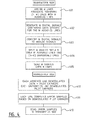
- M lines are assigned for downstream data transmission, with no data transmission on the remaining N-M lines, i.e. no data intended for the subscribers associated with the N-M unassigned lines is transmitted.
- the M lines are chosen such that for every unassigned line n out of the N-M unassigned lines there exists an assigned line m out of the M assigned lines for which the pilot bit (or bits in case of FDPS) on unassigned line n is the same as on assigned line m. For each such unassigned line n, a single line m' is selected from the set of assigned lines with the same pilot bit(s).
- a second step 402 M estimation symbols are generated for the M assigned subscriber lines, containing data specific to the M assigned subscriber lines. Digital time domain samples are generated for the M estimation symbols through an IFFT operation.
- an appropriate digital scaling may be applied to compensate for the split of the signal over two or more channels. Alternatively, the power split may be compensated by adjusting the gain of the line drivers corresponding with the two or more channels. In both cases, the appropriate scaling could be performed through a calibration step that is performed once, e.g. at system design or startup, or periodically, e.g. tracked during show time.
- analog time domain signals are created by passing the M digital time domain samples through M DACs.
- a fourth step 404 for each line m', the analog signal is split over line m' and its corresponding line(s) n.
- the transmit signals are put on the N subscriber lines over N line adaption units.
- each line m out of the M lines demodulates both the data and the pilot carriers, and each line n out of the N-M lines demodulates only the pilot carriers, and potentially some broadcast data such as a multiple access plan (MAP).
- MAP multiple access plan
- each line out of the N subscriber lines computes error samples based on the demodulated pilot carriers and in step 412 each line feeds the error samples back to the controller at a transmit opportunity.
- Walsh-Hadamard sequences can be defined in the form of Hadamard matrices H 2K , where 2K is the length of the sequence: H K
- the embodiment of figure 5 may be used.
- the skilled person will understand that the same principles apply for other values of M and N.
- the embodiment of figure 5 corresponds with the embodiment of figure 2 , with this difference that a number of phase invertors 505 have been introduced between the switch 503 and the transceiver circuitries 502 for lines L4-L8.
- Those phase inverters 505 are also controlled by the controller 504.
- the phase inverters may be set by the controller 504 to invert the phase in the time period t4-t8, as indicated with an asterisk in table 2 below.
- Another advantageous embodiment may use frequency dependent pilot carriers. E.g. two frequencies may be used, resulting in the situation of table 3 below: Table 3 Time/line t1 t2 t3 t4 L1 -1 -1 -1 -1 -1 -1 -1 -1 -1 L2 -1 1 -1 1 -1 1 -1 1 L3 -1 -1 1 1 -1 -1 1 1 L4 -1 1 1 -1 -1 1 1 -1 L5 -1 -1 -1 -1 1* 1* 1* L6 -1 1 -1 1 1* -1* 1* -1* L7 -1 -1 1 1 1* 1* -1* -1* L8 -1 1 1 -1 1* -1* -1* 1* * phase shift performed
- phase inverters may be provided for lines L3-L8.
- lines L1, L3, L5 and L7 are associated with DSP1, and lines L2, L4, L6, L8 with DSP2.
- the phase inverters may be set by the controller to invert the phase in the time period t2 to t4, as indicated with an asterisk in table 4 above. In that way the switch need not be reset at times t2, t3 and t4.
Landscapes
- Engineering & Computer Science (AREA)
- Signal Processing (AREA)
- Computer Networks & Wireless Communication (AREA)
- Cable Transmission Systems, Equalization Of Radio And Reduction Of Echo (AREA)
Priority Applications (1)
| Application Number | Priority Date | Filing Date | Title |
|---|---|---|---|
| EP13305667.1A EP2806571A1 (de) | 2013-05-23 | 2013-05-23 | Verfahren und Zugangsknoten zum Verbinden von Teilnehmeranschlüssen |
Applications Claiming Priority (1)
| Application Number | Priority Date | Filing Date | Title |
|---|---|---|---|
| EP13305667.1A EP2806571A1 (de) | 2013-05-23 | 2013-05-23 | Verfahren und Zugangsknoten zum Verbinden von Teilnehmeranschlüssen |
Publications (1)
| Publication Number | Publication Date |
|---|---|
| EP2806571A1 true EP2806571A1 (de) | 2014-11-26 |
Family
ID=48607185
Family Applications (1)
| Application Number | Title | Priority Date | Filing Date |
|---|---|---|---|
| EP13305667.1A Withdrawn EP2806571A1 (de) | 2013-05-23 | 2013-05-23 | Verfahren und Zugangsknoten zum Verbinden von Teilnehmeranschlüssen |
Country Status (1)
| Country | Link |
|---|---|
| EP (1) | EP2806571A1 (de) |
Cited By (1)
| Publication number | Priority date | Publication date | Assignee | Title |
|---|---|---|---|---|
| WO2018166262A1 (zh) * | 2017-03-14 | 2018-09-20 | 中兴通讯股份有限公司 | 一种数据反馈方法及装置 |
Citations (3)
| Publication number | Priority date | Publication date | Assignee | Title |
|---|---|---|---|---|
| US20100202281A1 (en) * | 2009-02-12 | 2010-08-12 | Gerhard Guenter Theodor Kramer | Simultaneous Estimation of Multiple Channel Coefficients Using a Common Probing Sequence |
| US20120106605A1 (en) * | 2010-10-29 | 2012-05-03 | Ashikhmin Alexei E | Detection and Correction of Impulse Noise in Communication Channel Crosstalk Estimates |
| EP2536034A1 (de) | 2011-06-14 | 2012-12-19 | Alcatel Lucent | Punkt-zu-Mehrpunkt-Übertragung über eine verdrahtete Schleifenanlage |
-
2013
- 2013-05-23 EP EP13305667.1A patent/EP2806571A1/de not_active Withdrawn
Patent Citations (4)
| Publication number | Priority date | Publication date | Assignee | Title |
|---|---|---|---|---|
| US20100202281A1 (en) * | 2009-02-12 | 2010-08-12 | Gerhard Guenter Theodor Kramer | Simultaneous Estimation of Multiple Channel Coefficients Using a Common Probing Sequence |
| US8218419B2 (en) | 2009-02-12 | 2012-07-10 | Alcatel Lucent | Simultaneous estimation of multiple channel coefficients using a common probing sequence |
| US20120106605A1 (en) * | 2010-10-29 | 2012-05-03 | Ashikhmin Alexei E | Detection and Correction of Impulse Noise in Communication Channel Crosstalk Estimates |
| EP2536034A1 (de) | 2011-06-14 | 2012-12-19 | Alcatel Lucent | Punkt-zu-Mehrpunkt-Übertragung über eine verdrahtete Schleifenanlage |
Cited By (1)
| Publication number | Priority date | Publication date | Assignee | Title |
|---|---|---|---|---|
| WO2018166262A1 (zh) * | 2017-03-14 | 2018-09-20 | 中兴通讯股份有限公司 | 一种数据反馈方法及装置 |
Similar Documents
| Publication | Publication Date | Title |
|---|---|---|
| US7369579B2 (en) | Method and system for timing controlled signal transmission in a point to multipoint power line communications system | |
| US7573822B1 (en) | Broadband network for coaxial cable using multi-carrier modulation | |
| US8942079B2 (en) | Method and apparatus for mapping/demapping modulation symbols in a mobile communication system | |
| JP5156128B2 (ja) | 無線通信システムにおける方法および装置 | |
| US20020075902A1 (en) | Optimum overhead framing techniques for ADSL DMT modems | |
| US20170338989A1 (en) | Peak-to-Average Ratio Reduction Method, Apparatus, Device, and System | |
| EP2391031A1 (de) | Niederstrommodus für die Vektordatenübertragung | |
| US10567037B2 (en) | Methods, devices and systems of supporting discontinuous operation in communication systems using vectoring | |
| CN102187634B (zh) | 用于生成在电缆传输系统中使用的前导信号的方法和设备 | |
| BRPI0116692B1 (pt) | sistema e processo para transmissão digital de dados, ponto a multiponto através da rede de eletricidade | |
| TW201025949A (en) | New frame and data pattern structure for multi-carrier systems | |
| WO2014176255A1 (en) | Allocating orthogonal frequency-division multiple access (ofdma) resources in data over cable services interface specifications (docsis) networks | |
| CN102301706B (zh) | 有线数字视频广播系统和处理预留音的方法 | |
| WO2014008069A1 (en) | Methods and systems of specifying coaxial resource allocation across a mac/phy interface | |
| US8750281B2 (en) | Variable-length training fields in coaxial communications | |
| CN103609032B (zh) | 通过有线环路设备来连接订户的具有点到多点传输能力的接入节点 | |
| KR20160035925A (ko) | 광가입자망에서의 직교 주파수 분할 다중 신호 전송방법 및 그 장치 | |
| JP2003008539A (ja) | 直交周波数分割多重によるマスター/スレーブデータ伝送 | |
| JP5221461B2 (ja) | 光伝送装置および光伝送方法 | |
| EP2806571A1 (de) | Verfahren und Zugangsknoten zum Verbinden von Teilnehmeranschlüssen | |
| WO2014133692A1 (en) | Constant-capacity physical resource blocks for upstream transmissions over coax | |
| EP3447981A1 (de) | Datenverarbeitungsverfahren und -vorrichtung | |
| US20150288498A1 (en) | Upstream Transmission Burst Configuration | |
| JP2003023409A (ja) | 直交周波数分割多重によるデータ伝送方法 | |
| KR20070047325A (ko) | 멀티 캐리어 통신 시스템 내에서의 파일롯 채널 전송 및수신을 위한 방법 및 장치 |
Legal Events
| Date | Code | Title | Description |
|---|---|---|---|
| PUAI | Public reference made under article 153(3) epc to a published international application that has entered the european phase |
Free format text: ORIGINAL CODE: 0009012 |
|
| 17P | Request for examination filed |
Effective date: 20130523 |
|
| AK | Designated contracting states |
Kind code of ref document: A1 Designated state(s): AL AT BE BG CH CY CZ DE DK EE ES FI FR GB GR HR HU IE IS IT LI LT LU LV MC MK MT NL NO PL PT RO RS SE SI SK SM TR |
|
| AX | Request for extension of the european patent |
Extension state: BA ME |
|
| R17P | Request for examination filed (corrected) |
Effective date: 20150526 |
|
| RBV | Designated contracting states (corrected) |
Designated state(s): AL AT BE BG CH CY CZ DE DK EE ES FI FR GB GR HR HU IE IS IT LI LT LU LV MC MK MT NL NO PL PT RO RS SE SI SK SM TR |
|
| RAP1 | Party data changed (applicant data changed or rights of an application transferred) |
Owner name: ALCATEL LUCENT |
|
| STAA | Information on the status of an ep patent application or granted ep patent |
Free format text: STATUS: THE APPLICATION IS DEEMED TO BE WITHDRAWN |
|
| 18D | Application deemed to be withdrawn |
Effective date: 20181201 |