EP2806492A1 - Production method for non-aqueous electrolyte secondary battery - Google Patents
Production method for non-aqueous electrolyte secondary battery Download PDFInfo
- Publication number
- EP2806492A1 EP2806492A1 EP13738170.3A EP13738170A EP2806492A1 EP 2806492 A1 EP2806492 A1 EP 2806492A1 EP 13738170 A EP13738170 A EP 13738170A EP 2806492 A1 EP2806492 A1 EP 2806492A1
- Authority
- EP
- European Patent Office
- Prior art keywords
- exterior body
- charge
- secondary battery
- aqueous electrolyte
- gas
- Prior art date
- Legal status (The legal status is an assumption and is not a legal conclusion. Google has not performed a legal analysis and makes no representation as to the accuracy of the status listed.)
- Granted
Links
Images


Classifications
-
- H—ELECTRICITY
- H01—ELECTRIC ELEMENTS
- H01M—PROCESSES OR MEANS, e.g. BATTERIES, FOR THE DIRECT CONVERSION OF CHEMICAL ENERGY INTO ELECTRICAL ENERGY
- H01M10/00—Secondary cells; Manufacture thereof
- H01M10/05—Accumulators with non-aqueous electrolyte
- H01M10/058—Construction or manufacture
-
- H—ELECTRICITY
- H01—ELECTRIC ELEMENTS
- H01M—PROCESSES OR MEANS, e.g. BATTERIES, FOR THE DIRECT CONVERSION OF CHEMICAL ENERGY INTO ELECTRICAL ENERGY
- H01M10/00—Secondary cells; Manufacture thereof
- H01M10/04—Construction or manufacture in general
- H01M10/0436—Small-sized flat cells or batteries for portable equipment
-
- H—ELECTRICITY
- H01—ELECTRIC ELEMENTS
- H01M—PROCESSES OR MEANS, e.g. BATTERIES, FOR THE DIRECT CONVERSION OF CHEMICAL ENERGY INTO ELECTRICAL ENERGY
- H01M10/00—Secondary cells; Manufacture thereof
- H01M10/05—Accumulators with non-aqueous electrolyte
-
- H—ELECTRICITY
- H01—ELECTRIC ELEMENTS
- H01M—PROCESSES OR MEANS, e.g. BATTERIES, FOR THE DIRECT CONVERSION OF CHEMICAL ENERGY INTO ELECTRICAL ENERGY
- H01M10/00—Secondary cells; Manufacture thereof
- H01M10/05—Accumulators with non-aqueous electrolyte
- H01M10/052—Li-accumulators
-
- H—ELECTRICITY
- H01—ELECTRIC ELEMENTS
- H01M—PROCESSES OR MEANS, e.g. BATTERIES, FOR THE DIRECT CONVERSION OF CHEMICAL ENERGY INTO ELECTRICAL ENERGY
- H01M10/00—Secondary cells; Manufacture thereof
- H01M10/42—Methods or arrangements for servicing or maintenance of secondary cells or secondary half-cells
- H01M10/44—Methods for charging or discharging
- H01M10/446—Initial charging measures
-
- H—ELECTRICITY
- H01—ELECTRIC ELEMENTS
- H01M—PROCESSES OR MEANS, e.g. BATTERIES, FOR THE DIRECT CONVERSION OF CHEMICAL ENERGY INTO ELECTRICAL ENERGY
- H01M10/00—Secondary cells; Manufacture thereof
- H01M10/42—Methods or arrangements for servicing or maintenance of secondary cells or secondary half-cells
- H01M10/52—Removing gases inside the secondary cell, e.g. by absorption
-
- H—ELECTRICITY
- H01—ELECTRIC ELEMENTS
- H01M—PROCESSES OR MEANS, e.g. BATTERIES, FOR THE DIRECT CONVERSION OF CHEMICAL ENERGY INTO ELECTRICAL ENERGY
- H01M50/00—Constructional details or processes of manufacture of the non-active parts of electrochemical cells other than fuel cells, e.g. hybrid cells
- H01M50/10—Primary casings; Jackets or wrappings
- H01M50/116—Primary casings; Jackets or wrappings characterised by the material
- H01M50/117—Inorganic material
- H01M50/119—Metals
-
- H—ELECTRICITY
- H01—ELECTRIC ELEMENTS
- H01M—PROCESSES OR MEANS, e.g. BATTERIES, FOR THE DIRECT CONVERSION OF CHEMICAL ENERGY INTO ELECTRICAL ENERGY
- H01M50/00—Constructional details or processes of manufacture of the non-active parts of electrochemical cells other than fuel cells, e.g. hybrid cells
- H01M50/10—Primary casings; Jackets or wrappings
- H01M50/116—Primary casings; Jackets or wrappings characterised by the material
- H01M50/121—Organic material
-
- H—ELECTRICITY
- H01—ELECTRIC ELEMENTS
- H01M—PROCESSES OR MEANS, e.g. BATTERIES, FOR THE DIRECT CONVERSION OF CHEMICAL ENERGY INTO ELECTRICAL ENERGY
- H01M50/00—Constructional details or processes of manufacture of the non-active parts of electrochemical cells other than fuel cells, e.g. hybrid cells
- H01M50/10—Primary casings; Jackets or wrappings
- H01M50/116—Primary casings; Jackets or wrappings characterised by the material
- H01M50/124—Primary casings; Jackets or wrappings characterised by the material having a layered structure
- H01M50/126—Primary casings; Jackets or wrappings characterised by the material having a layered structure comprising three or more layers
- H01M50/129—Primary casings; Jackets or wrappings characterised by the material having a layered structure comprising three or more layers with two or more layers of only organic material
-
- H—ELECTRICITY
- H01—ELECTRIC ELEMENTS
- H01M—PROCESSES OR MEANS, e.g. BATTERIES, FOR THE DIRECT CONVERSION OF CHEMICAL ENERGY INTO ELECTRICAL ENERGY
- H01M50/00—Constructional details or processes of manufacture of the non-active parts of electrochemical cells other than fuel cells, e.g. hybrid cells
- H01M50/10—Primary casings; Jackets or wrappings
- H01M50/131—Primary casings; Jackets or wrappings characterised by physical properties, e.g. gas permeability, size or heat resistance
- H01M50/133—Thickness
-
- H—ELECTRICITY
- H01—ELECTRIC ELEMENTS
- H01M—PROCESSES OR MEANS, e.g. BATTERIES, FOR THE DIRECT CONVERSION OF CHEMICAL ENERGY INTO ELECTRICAL ENERGY
- H01M10/00—Secondary cells; Manufacture thereof
- H01M10/04—Construction or manufacture in general
- H01M10/0472—Vertically superposed cells with vertically disposed plates
-
- H—ELECTRICITY
- H01—ELECTRIC ELEMENTS
- H01M—PROCESSES OR MEANS, e.g. BATTERIES, FOR THE DIRECT CONVERSION OF CHEMICAL ENERGY INTO ELECTRICAL ENERGY
- H01M10/00—Secondary cells; Manufacture thereof
- H01M10/05—Accumulators with non-aqueous electrolyte
- H01M10/052—Li-accumulators
- H01M10/0525—Rocking-chair batteries, i.e. batteries with lithium insertion or intercalation in both electrodes; Lithium-ion batteries
-
- H—ELECTRICITY
- H01—ELECTRIC ELEMENTS
- H01M—PROCESSES OR MEANS, e.g. BATTERIES, FOR THE DIRECT CONVERSION OF CHEMICAL ENERGY INTO ELECTRICAL ENERGY
- H01M10/00—Secondary cells; Manufacture thereof
- H01M10/05—Accumulators with non-aqueous electrolyte
- H01M10/058—Construction or manufacture
- H01M10/0585—Construction or manufacture of accumulators having only flat construction elements, i.e. flat positive electrodes, flat negative electrodes and flat separators
-
- H—ELECTRICITY
- H01—ELECTRIC ELEMENTS
- H01M—PROCESSES OR MEANS, e.g. BATTERIES, FOR THE DIRECT CONVERSION OF CHEMICAL ENERGY INTO ELECTRICAL ENERGY
- H01M50/00—Constructional details or processes of manufacture of the non-active parts of electrochemical cells other than fuel cells, e.g. hybrid cells
- H01M50/10—Primary casings; Jackets or wrappings
- H01M50/116—Primary casings; Jackets or wrappings characterised by the material
- H01M50/124—Primary casings; Jackets or wrappings characterised by the material having a layered structure
-
- Y—GENERAL TAGGING OF NEW TECHNOLOGICAL DEVELOPMENTS; GENERAL TAGGING OF CROSS-SECTIONAL TECHNOLOGIES SPANNING OVER SEVERAL SECTIONS OF THE IPC; TECHNICAL SUBJECTS COVERED BY FORMER USPC CROSS-REFERENCE ART COLLECTIONS [XRACs] AND DIGESTS
- Y02—TECHNOLOGIES OR APPLICATIONS FOR MITIGATION OR ADAPTATION AGAINST CLIMATE CHANGE
- Y02E—REDUCTION OF GREENHOUSE GAS [GHG] EMISSIONS, RELATED TO ENERGY GENERATION, TRANSMISSION OR DISTRIBUTION
- Y02E60/00—Enabling technologies; Technologies with a potential or indirect contribution to GHG emissions mitigation
- Y02E60/10—Energy storage using batteries
-
- Y—GENERAL TAGGING OF NEW TECHNOLOGICAL DEVELOPMENTS; GENERAL TAGGING OF CROSS-SECTIONAL TECHNOLOGIES SPANNING OVER SEVERAL SECTIONS OF THE IPC; TECHNICAL SUBJECTS COVERED BY FORMER USPC CROSS-REFERENCE ART COLLECTIONS [XRACs] AND DIGESTS
- Y02—TECHNOLOGIES OR APPLICATIONS FOR MITIGATION OR ADAPTATION AGAINST CLIMATE CHANGE
- Y02P—CLIMATE CHANGE MITIGATION TECHNOLOGIES IN THE PRODUCTION OR PROCESSING OF GOODS
- Y02P70/00—Climate change mitigation technologies in the production process for final industrial or consumer products
- Y02P70/50—Manufacturing or production processes characterised by the final manufactured product
-
- Y—GENERAL TAGGING OF NEW TECHNOLOGICAL DEVELOPMENTS; GENERAL TAGGING OF CROSS-SECTIONAL TECHNOLOGIES SPANNING OVER SEVERAL SECTIONS OF THE IPC; TECHNICAL SUBJECTS COVERED BY FORMER USPC CROSS-REFERENCE ART COLLECTIONS [XRACs] AND DIGESTS
- Y10—TECHNICAL SUBJECTS COVERED BY FORMER USPC
- Y10T—TECHNICAL SUBJECTS COVERED BY FORMER US CLASSIFICATION
- Y10T29/00—Metal working
- Y10T29/49—Method of mechanical manufacture
- Y10T29/49002—Electrical device making
- Y10T29/49108—Electric battery cell making
- Y10T29/4911—Electric battery cell making including sealing
Definitions
- the present invention relates to a manufacturing method of a non-aqueous electrolyte secondary battery storing an electrode laminate in which a separator is disposed between a positive electrode and a negative electrode and an electrolyte within an exterior body constituted by an exterior body and sealing the exterior body and having a charge step carrying out an electric charge via a terminal of the electrode laminate.
- a lithium ion secondary battery is known as a non-aqueous electrolyte secondary battery.
- the lithium ion secondary battery has high energy density, high operating voltage, small self-discharge, and superior features as compared with a conventional secondary battery such as a nickel-metal hydride battery or a lead storage battery.
- the lithium ion secondary battery is widely utilized for a small sized electronic equipment such as a laptop computer or a cellular phone and, furthermore, recently as a storage power supply of on-board and stationary type.
- a charge step of charging up to a full charge is carried out.
- gas is generated in association with a reaction of the electrolyte.
- a gas removal step of removing gas within the exterior body is carried out after the charge step. In such a gas removal step as described above, an operation of unsealing the exterior body is carried out.
- a Patent Document 1 discloses the manufacturing method of the battery having a sealing step of sealing the electrode laminate and a particular filing material into the exterior body, a first charge step of charging up to less than a full charge voltage, and a second charge step of charging to the full charge.
- the gas removal step is carried out using a particular filling material after the first charge step so that unsealing the exterior body in order to remove gas after the second charge step is not needed.
- an object of the present invention to provide a manufacturing method of a non-aqueous electrolyte secondary battery which can solve the above-described task.
- Patent Document 1 Japanese Patent Application First Publication (tokkai) No. 2008-262895
- a manufacturing method of a non-aqueous electrolyte secondary battery comprising: a seal step of storing an electrode laminate in which a separator is disposed between a positive electrode and a negative electrode and an electrolyte within an exterior body constituted by a laminate film and sealing the exterior body; a pressure application step of applying a pressure on the exterior body in which the electrode laminate is stored; a charge step of charging up to a full charge; a gas removal step of removing gas generated within the exterior body at the charge step with the exterior body unsealed; and a re-seal step of sealing the exterior body after the gas removal step.
- a manufacturing method of an non-aqueous electrolyte secondary battery comprising: a seal step of storing an electrode laminate in which a separator is disposed between a positive electrode and a negative electrode within an exterior body constituted by a laminate film and sealing the exterior body under a decreased pressure; a charge step of charging up to a full charge after the seal step; a gas removal step of removing gas generated within the exterior body at the charge step under a decreased pressure with the exterior body unsealed; and a re-seal step of sealing the exterior body after the gas removal step.
- the number of times of the gas removal steps are reduced and the influence of gas on battery characteristics can be suppressed.
- Figs. 1(a) and 1(b) show a cross sectional view of a non-aqueous electrolyte secondary battery manufactured by the manufacturing method for a secondary battery in a first preferred embodiment.
- Fig. 2 shows a process flowchart for explaining the manufacturing method for the secondary battery in the first preferred embodiment.
- Fig. 1(a) shows a perspective view of the non-aqueous electrolyte secondary battery and Fig. 1(b) shows a cross sectional view cut away along a line. A - A of Fig. 1(a) .
- a non-aqueous electrolyte secondary battery 1 manufactured by the manufacturing method in the first embodiment is a large capacity lithium ion secondary battery suitable for driving, for example, a vehicle in which the non-aqueous electrolyte secondary battery is mounted.
- a size of an electrode is, for example, 210mm x 297mm or 148mm x 210mm and a capacity of the battery is 4Ah or higher.
- Each of electrodes 3 of negative electrodes 3b and positive electrodes 3a and separators 4 is formed in a rectangular shape. Negative electrodes 3b and positive electrodes 3a are alternately laminated via separators 4. Negative electrodes 3b are respectively disposed on both ends of electrode laminate 5 in a laminating direction.
- Positive electrode 3a is an application of a cathode active material 10a onto a current collecting aluminum foil 9a and, as cathode active material 10a, a composite oxide such as LiCoO 2 , LiMnO 2 , or so forth is used.
- Negative electrode 3b is an application of an anode active material 10b onto a current collecting copper foil 9b and, as anode active material 9b, a graphite, amorphous carbon, or so forth is used.
- An insulating tape 11 to prevent a short circuit between negative electrodes 3b and positive electrodes 3a is pasted onto a boundary between cathode active material 10a and current collecting aluminum foil 9a.
- a negative electrode terminal 7b is connected to a tip section of a part extended from a current collecting copper foil 9b of negative electrode 3b of electrode laminate 5. One end section of negative electrode terminal 7b is connected to a part extended from current collecting copper foil 9b and the other end section of negative electrode terminal 7b is projected toward an outside of exterior body 6.
- a positive electrode terminal 7a has the same structure as negative electrode terminal 7b. Both of negative electrode terminal 7b and positive electrode terminal 7a may respectively be projected from one side of rectangular shaped exterior body 6. Or alternatively, both electrode terminals may respectively be projected from both mutually opposing sides of exterior body 6 of rectangular exterior body 6.
- the laminate film forming exterior body 6 is formed and laminated in an order of a heat fusion layer (inner layer), a metallic layer, and a protective layer
- the inner layer is formed of a polyolefin series resin.
- the metallic layer is formed of an aluminum foil.
- the outer layer is formed of a PET (polyethylene-telephthalate).
- a rectangular frame shaped space is formed over an outer peripheral edge section of electrode laminate 5 within exterior body 6 and functions as a gas accumulating section 8 to accumulate gas generated during a use of the secondary battery.
- the gas accumulating section can be utilized as a space to accumulate gas extruded from electrodes 3 of electrode laminate 5 at a pressure application step which will be described later.
- the manufacturing method of the secondary battery in the first embodiment includes: a sealing (a seal) step of storing electrode laminate 5 in which separators 4 are disposed between positive electrode 3a and negative electrode 3b and an electrolyte within exterior body 6 constituted by the laminate film and sealing the exterior body under a decreased pressure; a charging (a charge) step of charging up to a full charge after the sealing step; a gas removal step of removing gas under the decreased pressure with exterior body 6 opened (unsealed); and a re-sealing (re-seal) step of sealing exterior body 6 under the decreased pressure after the gas removal step.
- electrode laminate 5 is stored within exterior body 6, the electrolyte is injected into exterior body 6, and the opening of exterior body 6 is sealed under the decreased pressure.
- LiPF 6 lithium hexafluorophosphate
- LiBF 4 Lithium borofluoride
- LiClO 4 Lithium perchlorate
- One kind or plural kinds of solvents can be selected from PC (propylene carbonate), EC (ethylene carbonate), DEC (diethyl carbonate), and so forth.
- a degree of decreased pressure (a degree of vacuum) at the seal step is preferably about 1hPa through 100hPa.
- step ST102 charging up to a capacity of 100% (full charge) is carried out.
- step ST103 part of exterior body 6 is unsealed and gas generated within exterior body 6 is externally exhausted under the decreased pressure.
- the pressure decreased state may be carried out after the unsealing of exterior body 6 or exterior body 6 may be unsealed under the pressure decreased state.
- step ST104 exterior body 6 unsealed at the gas removal step is sealed under pressure decreased state.
- the degree of decreased pressure at the gas removal step and at the re-seal step is preferably about 1hPa through 100hPa.
- gas accumulating section 8 can be utilized as a space for housing gas generated during the use of the secondary battery. Since exterior body 6 is formed of the flexible laminate film, gas accumulating section 8 functions as the space for accumulating gas during the manufacture of the secondary battery and during the use of the secondary battery. It should be noted that, in a case where the exterior body is structured to have a rigidity such as a hard casing, it becomes difficult to store a plurality of cells within a module when the exterior body is deformed due to gas accumulated during the manufacture of the secondary battery. Hence, the exterior body may preferably be formed of the flexible laminate film.
- the seal step is carried out under the decreased pressure.
- gas generated when electrode laminate 5 and the electrolyte are stored in exterior body 6 at the seal step can smoothly be removed. Therefore, the influence of gas at the charge step can be reduced without carrying out the gas removal step with exterior body 6 unsealed before the charge step.
- gas is removed under the decreased pressure after the charge step. Gas generated within exterior body 6 at the charge step can smoothly be removed to the outside of exterior body 6. Consequently, the number of times of the gas removal steps can be reduced and the influence of gas on the battery characteristics can be suppressed.
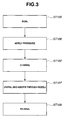
- Fig. 3 shows a process flowchart for explaining the manufacturing method for the secondary battery in a second preferred embodiment according to the present invention.
- a pressure application step of applying a pressure to exterior body 6 sealed at the seal step is interposed between the seal step and the charge step.
- the same steps as the manufacturing method in the first embodiment designate the same signs as the first embodiment and their explanations will be omitted.
- the same elements as the non-aqueous electrolyte secondary battery in the first embodiment designate the same signs and their explanations will be omitted.
- the manufacturing method of the secondary battery in the second embodiment includes: storing electrode laminate 5 in which separators 4 are disposed between positive electrodes 3a and negative electrodes 3b and the electrolyte within exterior body 6 constituted by the laminate film and sealing exterior body 6; a pressure application step of applying a pressure on exterior body 6 in which the electrode laminate 5 is stored; a charge step of charging up to the full charge; a gas removal step of removing gas generated within exterior body 6 at the charge step by unsealing exterior body 6 inserting a nozzle into an unsealed port of the exterior body and by absorbing gas within the inside of exterior body 6; and a re-seal step of re-sealing exterior body 6 after the gas removal step.
- electrode laminate 5 is stored within exterior body 6, the electrolyte is injected within exterior body 6, and an opening of exterior body 6 is sealed.
- Those used in the first embodiment can be utilized for the electrolyte and the solvent.
- a flat plate press working is carried out in a state in which exterior body 6 is sealed.
- gas within electrode laminate 5 is moved to an outside of electrode laminate 5 but within exterior body 6.
- a surface of the flat plate press is made of a material having an insulating characteristic and may, preferably, be made of a resin material.
- gas accumulating section 8 of exterior body 6 is deflated. However, gas is moved so that the flexible laminate film becomes inflated and gas can be accumulated within gas accumulating section 8.
- the flat plate press working may, preferably, be carried out under a pressure about 1kgf/cm 2 through 100kgf/cm 2 .
- the charge step shown in a step ST102 the charge is carried out up to 100% (full charge) of capacity.
- the gas removal step shown in a step ST107 a part of exterior body is unsealed, a nozzle is inserted through an unsealed port, and gas of an inside of exterior body 6 is absorbed and removed via the nozzle.
- the re-seal step shown in a step ST108 the unsealed exterior body 6 is sealed.
- seal step (step ST105), the gas removal step (step ST107), and the re-seal step (step ST108) in the second embodiment may be carried out under the decreased pressure as will be described later in a modification example 2B.
- the pressure application step is provided so that gas generated within exterior body 6 after the seal step can be moved within gas accumulating section 8 from an inside of electrode laminate 5.
- the influence of gas at the charge step can be reduced without carrying out the gas removal step with exterior body 6 unsealed before the charge step.
- the gas removal step is carried out after the charge step.
- a roll press working using a roll is carried out in place of the flat plate.
- the roll press working using the roll is carried out in a state in which exterior body 6 is sealed so that gas within electrode laminate 5 is moved to the outside of electrode laminate 5.
- gas accumulating section 8 of exterior body 6 is deflated.
- the movement of gas causes the flexible laminate film is inflated and gas can be accumulated within gas accumulating section 8.
- the roll press working may preferably be carried out under the pressure about 1kgf/cm 2 through 100kgf/cm 2 and a movement of a roll press may, preferably, be moved from the outside of exterior body 6 along a surface of electrodes 3 of electrode laminate 5.
- a surface of the roll press is made of a material having an insulating characteristic and may preferably be made of a resin material.
- insulating tape 11 pasted onto a boundary part of each cathode active material and a cathode (positive electrode) current collecting copper foil is provided.
- insulating tape 11 may be pasted on negative electrode 3b side.
- the roller may be rolled and moved from one end section at negative electrode terminal 7b side on which insulating tape 11 is pasted toward the other end section opposite to the one end section.
- gas accumulated in a proximity of insulating tape 11 can effectively be moved.
- Gas generated within exterior body 6 after the seal step can smoothly be moved toward an inside of gas accumulating section 8 from electrode laminate 5 by providing the pressure application step during which the roll press working is carried out.
- the influence of gas at the charge step can be reduced.
- the gas removal step is carried out after the charge step.
- the gas removal step in the second embodiment is not carried out through the absorbing method through the nozzle but is carried out under the decreased pressure and the re-seal step is carried out under the decreased pressure.
- gas generated at the charge step and gas moved at the pressure application step and accumulated at gas accumulating section 8 can smoothly be removed to the outside of exterior body 6.
- the seal step in the second embodiment is carried out under the decreased pressure.
- gas generated when electrode laminate 5 and the electrolyte are stored within exterior body 6 can smoothly be removed to the outside of exterior body 6.
- Fig. 4 shows a process flowchart for explaining the method of manufacturing the secondary battery in a third preferred embodiment.
- the same steps as the manufacturing the secondary battery in the first embodiment designate the corresponding steps in the third embodiment and their detailed explanations will herein be omitted.
- the same elements as the non-aqueous electrolyte secondary battery in the first embodiment designate the corresponding elements in the third embodiments.
- the manufacturing method for the secondary battery in the third embodiment includes: the seal step of storing electrode laminate 5 in which separators 4 are disposed between positive electrodes 3a and negative electrodes 3b and the electrolyte within exterior body 6 constituted by the laminate film and sealing exterior body 6, the pressure application step of applying the pressure to exterior body 6 in which electrode laminate 5 is stored; a first charge step of charging up to a voltage lower than a voltage of the full charge after the pressure application step; a second charge step of charging up to the full charge without unsealing of exterior body 6 after the first charge step; gas removal step of unsealing exterior body 6, inserting the nozzle into the unsealed port of exterior body 6, and absorbing gas to remove gas which is generated within exterior body 6 at the second charge step; and a re-seal step of sealing exterior body 6 after the gas removal step.
- electrode laminate 5 is stored in exterior body 6, the electrolyte is injected in exterior body 6, and the opening (or unsealed port) of exterior body 6 is sealed.
- Those used in the first embodiment can be utilized for the electrolyte and the solvent.
- the charge is carried out up to a voltage lower than the voltage of the full charge, for example, up to about 5% through 50% of the capacity.
- the charge is carried out up to 100% of the capacity (full charge).
- step ST107 a part of exterior body 6 is unsealed, the nozzle is inserted into the unsealed port, gas within the inside of exterior body 6 is absorbed and gas is removed.
- step ST108 the unsealed exterior body 6 is sealed.
- the gas removal step is carried out after the second charge step.
- an introduction of a reduction of the battery characteristics due to gas generated within exterior body 6 at the charge step can be suppressed. Consequently, the number of times of the gas removal steps can be reduced and the influence of gas on the battery characteristics can be suppressed.
- step ST106 in Fig. 4 the roll press working using the roll is carried out in the same way as modification example 2A of the second embodiment in place of the use of the flat plate so that gas generated within exterior body 6 can smoothly be moved from the inside of electrode laminate 5 to the inside of gas accumulating section 8.
- the gas removal step in the third embodiment is carried out under the decreased pressure so that gas generated at the charge step can smoothly be removed to the outside of exterior body 6.
- the seal step in the third embodiment is carried out under the decreased pressure.
- Fig. 5 shows a process flowchart for explaining the manufacturing method of the secondary battery in a fourth preferred embodiment.
- the pressure application step is carried out. This is different from the third embodiment.
- the manufacturing method of the secondary battery in the fourth embodiment includes: the seal step of storing electrode laminate 5 in which separators 4 are disposed between positive electrodes 3a and negative electrodes 3b and electrolyte within exterior body 6 constituted by the laminate film and sealing exterior body 6; the first charge step of charging up to a voltage lower than the full charge after the seal step; the pressure application step of applying the pressure on exterior body 6 in which the electrode laminate is stored after the first charge step; a second charge step of charging up to the full charge without unsealing exterior body 6 after the pressure application state; the gas removal step of removing gas generated within exterior body 6 at the second charge step by unsealing exterior body 6, inserting the nozzle through the unsealed port, and absorbing gas to remove gas; and re-seal step of sealing exterior body 6 after the gas removal step.
- electrode laminate 5 is stored in exterior body 6, the electrolyte is injected into exterior body, and the opening of exterior body is sealed.
- Those used in the first embodiment can be utilized as the electrolyte and the solvent.
- the charge is carried out up to a voltage lower than the full charge, for example, up to about 5% to 50% of the capacity.
- the flat press working using the flat plate is carried out in a state in which exterior body 6 is sealed.
- a large quantity of gas generated within exterior body 6 can be moved from the inside of electrode laminate 5 to the inside of gas accumulating section 5.
- the charge is carried out up to 100% (full charge) of the capacity.
- step ST107 a part of exterior body 6 is unsealed, the nozzle is inserted through an unsealed port, gas within the inside of exterior body is absorbed via the nozzle and is removed.
- step ST108 unsealed exterior body 6 is sealed.
- the pressure application step is carried out between the first charge step and the second charge step.
- a large quantity of gas generated within exterior body 6 at the seal step and at the first charge step can be moved from the inside of electrode laminate 5 to the inside of gas accumulating section 8.
- the gas removal step is carried out after the second charge step.
- gas accumulating section 8 to house gas generated during the use of secondary battery 1 is utilized as gas accumulating section 8 to house gas moved from the inside of electrode laminate 5 during the manufacturing.
- gas accumulating section 8 used during the manufacturing is cut from secondary battery 1 is not needed and secondary battery 1 can be manufactured.
- the roller is moved from one end section of insulating tape 11 pasted on a boundary part between the active material layer and current collecting copper foil constituting the positive electrode or the negative electrode toward a direction of the other end section which is opposite to the one end section.
- gas accumulated in the proximity of insulating tape 11 can effectively be moved.
- the pressure decrease may be carried out after exterior body 6 is unsealed and the unseal may be carried out after the pressure decrease.
- the manufacturing method of the secondary battery in each of the preferred embodiments may include another pressure application step which applies the pressure in the lamination direction in a state in which the secondary batteries (cells) is plurally laminated to constitute a module.
- the manufacturing method of the secondary battery according to the present invention may, of course, be applied to such a secondary battery that the electrode laminate in which the separators are disposed between the positive electrodes and the negative electrodes is spirally wound.
Landscapes
- Chemical & Material Sciences (AREA)
- Chemical Kinetics & Catalysis (AREA)
- Electrochemistry (AREA)
- General Chemical & Material Sciences (AREA)
- Engineering & Computer Science (AREA)
- Manufacturing & Machinery (AREA)
- Inorganic Chemistry (AREA)
- Secondary Cells (AREA)
- Connection Of Batteries Or Terminals (AREA)
- Battery Electrode And Active Subsutance (AREA)
- Sealing Battery Cases Or Jackets (AREA)
Abstract
Description
- The present invention relates to a manufacturing method of a non-aqueous electrolyte secondary battery storing an electrode laminate in which a separator is disposed between a positive electrode and a negative electrode and an electrolyte within an exterior body constituted by an exterior body and sealing the exterior body and having a charge step carrying out an electric charge via a terminal of the electrode laminate.
- For example, a lithium ion secondary battery is known as a non-aqueous electrolyte secondary battery. The lithium ion secondary battery has high energy density, high operating voltage, small self-discharge, and superior features as compared with a conventional secondary battery such as a nickel-metal hydride battery or a lead storage battery. The lithium ion secondary battery is widely utilized for a small sized electronic equipment such as a laptop computer or a cellular phone and, furthermore, recently as a storage power supply of on-board and stationary type.
- In manufacturing processes of the lithium ion secondary battery, after a sealing step of storing and sealing the electrode laminate in which separators are disposed between a plurality of electrodes and the electrolyte within the exterior body constituted by the laminate film, a charge step of charging up to a full charge is carried out.
- In the sealing step or charge step, gas is generated in association with a reaction of the electrolyte. In order to prevent a reduction in the battery characteristics due to gas resided within the exterior body, a gas removal step of removing gas within the exterior body is carried out after the charge step. In such a gas removal step as described above, an operation of unsealing the exterior body is carried out.
- A
Patent Document 1 discloses the manufacturing method of the battery having a sealing step of sealing the electrode laminate and a particular filing material into the exterior body, a first charge step of charging up to less than a full charge voltage, and a second charge step of charging to the full charge. According to this manufacturing method, the gas removal step is carried out using a particular filling material after the first charge step so that unsealing the exterior body in order to remove gas after the second charge step is not needed. - However, in the manufacturing method described in the above-described
Patent Document 1, although the gas removal step can be eliminated which is carried out after the second charge step, gas generated after the second charge step reduces the battery characteristics. - Hence, it is preferable to suppress an influence of gas on the battery characteristics, in the manufacturing method of the battery. In addition, in a case where the reduction of the battery characteristic due to a contact of the electrode or electrolyte on moisture in the air or oxygen and a safety of the manufacturing step are taken into consideration, it is desirable to reduce number of times of the gas removal steps which unseal the exterior body.
- It is, therefore, an object of the present invention to provide a manufacturing method of a non-aqueous electrolyte secondary battery which can solve the above-described task.
- Patent Document 1: Japanese Patent Application First Publication (tokkai) No.
2008-262895 - According to one aspect of the present invention, there is provided a manufacturing method of a non-aqueous electrolyte secondary battery, comprising: a seal step of storing an electrode laminate in which a separator is disposed between a positive electrode and a negative electrode and an electrolyte within an exterior body constituted by a laminate film and sealing the exterior body; a pressure application step of applying a pressure on the exterior body in which the electrode laminate is stored; a charge step of charging up to a full charge; a gas removal step of removing gas generated within the exterior body at the charge step with the exterior body unsealed; and a re-seal step of sealing the exterior body after the gas removal step.
- According to another aspect of the present invention, there is provided a manufacturing method of an non-aqueous electrolyte secondary battery, comprising: a seal step of storing an electrode laminate in which a separator is disposed between a positive electrode and a negative electrode within an exterior body constituted by a laminate film and sealing the exterior body under a decreased pressure; a charge step of charging up to a full charge after the seal step; a gas removal step of removing gas generated within the exterior body at the charge step under a decreased pressure with the exterior body unsealed; and a re-seal step of sealing the exterior body after the gas removal step.
- According to the present invention, the number of times of the gas removal steps are reduced and the influence of gas on battery characteristics can be suppressed.
-
-
Figs. 1(a) and 1(b) are cross sectional views representing a secondary battery manufactured in a manufacturing method for a secondary battery in a first preferred embodiment. -
Fig. 2 is a process flowchart for explaining the manufacturing method of the secondary battery in the first preferred embodiment. -
Fig. 3 is a process flowchart for explaining the manufacturing method of the secondary battery in a second preferred embodiment. -
Fig. 4 is a process flowchart for explaining the manufacturing method of the secondary battery in a third preferred embodiment. -
Fig. 5 is a process flowchart for explaining the manufacturing method of the secondary battery in a fourth preferred embodiment. - Hereinafter, specific embodiments according to the present invention will be explained with reference to the drawings.
-
Figs. 1(a) and 1(b) show a cross sectional view of a non-aqueous electrolyte secondary battery manufactured by the manufacturing method for a secondary battery in a first preferred embodiment.Fig. 2 shows a process flowchart for explaining the manufacturing method for the secondary battery in the first preferred embodiment.Fig. 1(a) shows a perspective view of the non-aqueous electrolyte secondary battery andFig. 1(b) shows a cross sectional view cut away along a line. A - A ofFig. 1(a) . - As shown in
Fig. 1(a) , a non-aqueous electrolytesecondary battery 1 manufactured by the manufacturing method in the first embodiment is a large capacity lithium ion secondary battery suitable for driving, for example, a vehicle in which the non-aqueous electrolyte secondary battery is mounted. A size of an electrode is, for example, 210mm x 297mm or 148mm x 210mm and a capacity of the battery is 4Ah or higher. - Non-aqueous electrolyte
secondary battery 1 manufactured in the first embodiment, as shown inFig. 1(b) , includes: anelectrode laminate 5 in whichseparators 4 are disposed betweenpositive electrodes 3a andnegative electrodes 3b; an electrolyte (electrolytic solution); anexterior body 6 constituted by alaminate film 6a which seals these.
Exterior body 6 may be formed by folding one sheet oflaminate film 6a and by thermally sealing three peripheral sides or may be formed by overlapping two sheets of laminate films and by thermally sealing four of the peripheral sides. A thickness oflaminate film 6a is preferably about 100 µm ∼200 µm and a flexible film. - Each of electrodes 3 of
negative electrodes 3b andpositive electrodes 3a andseparators 4 is formed in a rectangular shape.Negative electrodes 3b andpositive electrodes 3a are alternately laminated viaseparators 4.Negative electrodes 3b are respectively disposed on both ends ofelectrode laminate 5 in a laminating direction. -
Positive electrode 3a is an application of a cathodeactive material 10a onto a current collectingaluminum foil 9a and, as cathodeactive material 10a, a composite oxide such as LiCoO2, LiMnO2, or so forth is used.Negative electrode 3b is an application of an anodeactive material 10b onto a current collectingcopper foil 9b and, as anodeactive material 9b, a graphite, amorphous carbon, or so forth is used. Aninsulating tape 11 to prevent a short circuit betweennegative electrodes 3b andpositive electrodes 3a is pasted onto a boundary between cathodeactive material 10a and current collectingaluminum foil 9a. - A
negative electrode terminal 7b is connected to a tip section of a part extended from a current collectingcopper foil 9b ofnegative electrode 3b ofelectrode laminate 5. One end section ofnegative electrode terminal 7b is connected to a part extended from current collectingcopper foil 9b and the other end section ofnegative electrode terminal 7b is projected toward an outside ofexterior body 6. Apositive electrode terminal 7a has the same structure asnegative electrode terminal 7b. Both ofnegative electrode terminal 7b andpositive electrode terminal 7a may respectively be projected from one side of rectangular shapedexterior body 6. Or alternatively, both electrode terminals may respectively be projected from both mutually opposing sides ofexterior body 6 of rectangularexterior body 6. - The laminate film forming
exterior body 6 is formed and laminated in an order of a heat fusion layer (inner layer), a metallic layer, and a protective layer - (outer layer) (not shown). The inner layer is formed of a polyolefin series resin. The metallic layer is formed of an aluminum foil. The outer layer is formed of a PET (polyethylene-telephthalate).
- In addition, as shown in
Fig. 1(a) , a rectangular frame shaped space is formed over an outer peripheral edge section ofelectrode laminate 5 withinexterior body 6 and functions as agas accumulating section 8 to accumulate gas generated during a use of the secondary battery. In addition, in the manufacturing method of the secondary battery, the gas accumulating section can be utilized as a space to accumulate gas extruded from electrodes 3 ofelectrode laminate 5 at a pressure application step which will be described later. - As shown in
Fig. 2 , the manufacturing method of the secondary battery in the first embodiment includes: a sealing (a seal) step of storingelectrode laminate 5 in whichseparators 4 are disposed betweenpositive electrode 3a andnegative electrode 3b and an electrolyte withinexterior body 6 constituted by the laminate film and sealing the exterior body under a decreased pressure; a charging (a charge) step of charging up to a full charge after the sealing step; a gas removal step of removing gas under the decreased pressure withexterior body 6 opened (unsealed); and a re-sealing (re-seal) step of sealingexterior body 6 under the decreased pressure after the gas removal step. - In the seal step shown in a step ST101 in
Fig. 2 ,electrode laminate 5 is stored withinexterior body 6, the electrolyte is injected intoexterior body 6, and the opening ofexterior body 6 is sealed under the decreased pressure. LiPF6 (lithium hexafluorophosphate), LiBF4 (Lithium borofluoride), LiClO4(Lithium perchlorate) or so forth can be used as the electrolyte. One kind or plural kinds of solvents can be selected from PC (propylene carbonate), EC (ethylene carbonate), DEC (diethyl carbonate), and so forth. In the seal step, whenexterior body 6 is sealed,gas accumulating section 8 thatexterior body 6 has is deflated. A degree of decreased pressure (a degree of vacuum) at the seal step is preferably about 1hPa through 100hPa. - In the charge step shown in a step ST102, charging up to a capacity of 100% (full charge) is carried out.
In the gas removal step shown in step ST103, part ofexterior body 6 is unsealed and gas generated withinexterior body 6 is externally exhausted under the decreased pressure. In the gas removal step, the pressure decreased state may be carried out after the unsealing ofexterior body 6 orexterior body 6 may be unsealed under the pressure decreased state. In the re-seal step shown in step ST104,exterior body 6 unsealed at the gas removal step is sealed under pressure decreased state. The degree of decreased pressure at the gas removal step and at the re-seal step is preferably about 1hPa through 100hPa. - In the re-sealing (re-seal) step, the pressure decrease is carried out so that
exterior body 6 is again deflated.
Thus,gas accumulating section 8 can be utilized as a space for housing gas generated during the use of the secondary battery. Sinceexterior body 6 is formed of the flexible laminate film,gas accumulating section 8 functions as the space for accumulating gas during the manufacture of the secondary battery and during the use of the secondary battery.
It should be noted that, in a case where the exterior body is structured to have a rigidity such as a hard casing, it becomes difficult to store a plurality of cells within a module when the exterior body is deformed due to gas accumulated during the manufacture of the secondary battery. Hence, the exterior body may preferably be formed of the flexible laminate film. - As described above, according to the manufacturing method of the secondary battery in the first embodiment, the seal step is carried out under the decreased pressure. Thus, gas generated when
electrode laminate 5 and the electrolyte are stored inexterior body 6 at the seal step can smoothly be removed. Therefore, the influence of gas at the charge step can be reduced without carrying out the gas removal step withexterior body 6 unsealed before the charge step.
In addition, in the first embodiment, gas is removed under the decreased pressure after the charge step. Gas generated withinexterior body 6 at the charge step can smoothly be removed to the outside ofexterior body 6. Consequently, the number of times of the gas removal steps can be reduced and the influence of gas on the battery characteristics can be suppressed. - Hereinafter, the manufacturing method of the secondary battery in other preferred embodiments and modification of each of the other preferred embodiments will be described.
-
Fig. 3 shows a process flowchart for explaining the manufacturing method for the secondary battery in a second preferred embodiment according to the present invention. - In the second embodiment, a pressure application step of applying a pressure to
exterior body 6 sealed at the seal step is interposed between the seal step and the charge step. - In the second embodiment, the same steps as the manufacturing method in the first embodiment designate the same signs as the first embodiment and their explanations will be omitted. In addition, in the second embodiment, the same elements as the non-aqueous electrolyte secondary battery in the first embodiment designate the same signs and their explanations will be omitted.
- As shown in
Fig. 3 , the manufacturing method of the secondary battery in the second embodiment includes: storingelectrode laminate 5 in whichseparators 4 are disposed betweenpositive electrodes 3a andnegative electrodes 3b and the electrolyte withinexterior body 6 constituted by the laminate film and sealingexterior body 6; a pressure application step of applying a pressure onexterior body 6 in which theelectrode laminate 5 is stored; a charge step of charging up to the full charge; a gas removal step of removing gas generated withinexterior body 6 at the charge step by unsealingexterior body 6 inserting a nozzle into an unsealed port of the exterior body and by absorbing gas within the inside ofexterior body 6; and a re-seal step of re-sealingexterior body 6 after the gas removal step. - In the seal step shown in step ST105 in
Fig. 3 ,electrode laminate 5 is stored withinexterior body 6, the electrolyte is injected withinexterior body 6, and an opening ofexterior body 6 is sealed. Those used in the first embodiment can be utilized for the electrolyte and the solvent. - In the pressure application step in the second embodiment shown in a step ST106 in
Fig. 3 , a flat plate press working is carried out in a state in whichexterior body 6 is sealed. Thus, gas withinelectrode laminate 5 is moved to an outside ofelectrode laminate 5 but withinexterior body 6. A surface of the flat plate press is made of a material having an insulating characteristic and may, preferably, be made of a resin material. After the seal step,gas accumulating section 8 ofexterior body 6 is deflated. However, gas is moved so that the flexible laminate film becomes inflated and gas can be accumulated withingas accumulating section 8. The flat plate press working may, preferably, be carried out under a pressure about 1kgf/cm2 through 100kgf/cm2. - In the charge step shown in a step ST102, the charge is carried out up to 100% (full charge) of capacity. In the gas removal step shown in a step ST107, a part of exterior body is unsealed, a nozzle is inserted through an unsealed port, and gas of an inside of
exterior body 6 is absorbed and removed via the nozzle. In the re-seal step shown in a step ST108, the unsealedexterior body 6 is sealed. - It should be noted that the seal step (step ST105), the gas removal step (step ST107), and the re-seal step (step ST108) in the second embodiment may be carried out under the decreased pressure as will be described later in a modification example 2B.
- According to the manufacturing method for the secondary battery in the second embodiment, the pressure application step is provided so that gas generated within
exterior body 6 after the seal step can be moved withingas accumulating section 8 from an inside ofelectrode laminate 5. Thus, the influence of gas at the charge step can be reduced without carrying out the gas removal step withexterior body 6 unsealed before the charge step.
In addition, in the second embodiment, the gas removal step is carried out after the charge step. Thus, an introduction of a reduction of the battery characteristics due to gas generated withinexterior body 6 at the charge step can be suppressed.
Consequently, the number of times of the gas removal steps can be reduced and the influence of gas on the battery characteristics can be suppressed. - In the pressure application step in the second embodiment, a roll press working using a roll is carried out in place of the flat plate.
- In this pressure application step, the roll press working using the roll is carried out in a state in which
exterior body 6 is sealed so that gas withinelectrode laminate 5 is moved to the outside ofelectrode laminate 5. After the seal step,gas accumulating section 8 ofexterior body 6 is deflated. However, the movement of gas causes the flexible laminate film is inflated and gas can be accumulated withingas accumulating section 8. The roll press working may preferably be carried out under the pressure about 1kgf/cm2 through 100kgf/cm2 and a movement of a roll press may, preferably, be moved from the outside ofexterior body 6 along a surface of electrodes 3 ofelectrode laminate 5. - A surface of the roll press is made of a material having an insulating characteristic and may preferably be made of a resin material.
In either of types in which both ofnegative electrode terminal 7b andpositive electrode terminal 7a are projected from one side ofexterior body 6 and in whichnegative electrode terminal 7b andpositive electrode terminal 7a are respectively projected from opposing respective sides ofexterior body 6, insulatingtape 11 pasted onto a boundary part of each cathode active material and a cathode (positive electrode) current collecting copper foil is provided. In this case, it is preferable to move a roller from one end section (a side at whichpositive electrode terminal 7a is disposed) on which insulatingtape 11 is pasted toward a direction of the other end section which is opposite to the one end section.
In place of pasting insulatingtape 11 on thepositive electrode 3a side, insulatingtape 11 may be pasted onnegative electrode 3b side. In this case, the roller may be rolled and moved from one end section atnegative electrode terminal 7b side on which insulatingtape 11 is pasted toward the other end section opposite to the one end section. Thus, gas accumulated in a proximity of insulatingtape 11 can effectively be moved. - Gas generated within
exterior body 6 after the seal step can smoothly be moved toward an inside ofgas accumulating section 8 fromelectrode laminate 5 by providing the pressure application step during which the roll press working is carried out. Thus, without carrying out the gas removal step with exterior body unsealed before the charge step, the influence of gas at the charge step can be reduced.
In addition, in the second embodiment, the gas removal step is carried out after the charge step. Thus, an introduction of the reduction of the battery characteristics due to the gas generated withinexterior body 6 at the charge step can be suppressed. Consequently, the number of times of the gas removal steps are reduced and the influence of gas on the battery characteristics can be suppressed. - The gas removal step in the second embodiment is not carried out through the absorbing method through the nozzle but is carried out under the decreased pressure and the re-seal step is carried out under the decreased pressure. Thus, gas generated at the charge step and gas moved at the pressure application step and accumulated at
gas accumulating section 8 can smoothly be removed to the outside ofexterior body 6. - In addition, the seal step in the second embodiment is carried out under the decreased pressure. Thus, gas generated when
electrode laminate 5 and the electrolyte are stored withinexterior body 6 can smoothly be removed to the outside ofexterior body 6. It should be noted that modification example 2A and modification example 2B may be combined and applied to the present invention. -
Fig. 4 shows a process flowchart for explaining the method of manufacturing the secondary battery in a third preferred embodiment. - In the third embodiment, the same steps as the manufacturing the secondary battery in the first embodiment designate the corresponding steps in the third embodiment and their detailed explanations will herein be omitted. In addition, the same elements as the non-aqueous electrolyte secondary battery in the first embodiment designate the corresponding elements in the third embodiments.
- As shown in
Fig. 4 , the manufacturing method for the secondary battery in the third embodiment includes: the seal step of storingelectrode laminate 5 in whichseparators 4 are disposed betweenpositive electrodes 3a andnegative electrodes 3b and the electrolyte withinexterior body 6 constituted by the laminate film and sealingexterior body 6, the pressure application step of applying the pressure toexterior body 6 in whichelectrode laminate 5 is stored; a first charge step of charging up to a voltage lower than a voltage of the full charge after the pressure application step; a second charge step of charging up to the full charge without unsealing ofexterior body 6 after the first charge step; gas removal step of unsealingexterior body 6, inserting the nozzle into the unsealed port ofexterior body 6, and absorbing gas to remove gas which is generated withinexterior body 6 at the second charge step; and a re-seal step of sealingexterior body 6 after the gas removal step. - At the seal step shown in a step ST105 in
Fig. 4 ,electrode laminate 5 is stored inexterior body 6, the electrolyte is injected inexterior body 6, and the opening (or unsealed port) ofexterior body 6 is sealed. Those used in the first embodiment can be utilized for the electrolyte and the solvent. - In the pressure application step shown in a step ST106 in
Fig. 4 , the flat plate press working using the flat plate is carried out withexterior body 6 sealed in the same way as the second embodiment. Thus, gas generated withinexterior body 6 is moved from the inside ofelectrode laminate 5 to an inside ofgas accumulating section 8. - In the first charge step shown in a step ST111, the charge is carried out up to a voltage lower than the voltage of the full charge, for example, up to about 5% through 50% of the capacity. In the second charge step shown in step ST112, the charge is carried out up to 100% of the capacity (full charge).
- In the gas removal step shown in step ST107, a part of
exterior body 6 is unsealed, the nozzle is inserted into the unsealed port, gas within the inside ofexterior body 6 is absorbed and gas is removed.
In the re-seal step shown in a step ST108, the unsealedexterior body 6 is sealed. - According to the manufacturing method of the secondary battery in the third embodiment, the gas removal step is carried out after the second charge step. Thus, an introduction of a reduction of the battery characteristics due to gas generated within
exterior body 6 at the charge step can be suppressed. Consequently, the number of times of the gas removal steps can be reduced and the influence of gas on the battery characteristics can be suppressed. - In the pressure application step in the third embodiment (step ST106 in
Fig. 4 ), the roll press working using the roll is carried out in the same way as modification example 2A of the second embodiment in place of the use of the flat plate so that gas generated withinexterior body 6 can smoothly be moved from the inside ofelectrode laminate 5 to the inside ofgas accumulating section 8. - In the same way as modification example 2B of the second embodiment, the gas removal step in the third embodiment is carried out under the decreased pressure so that gas generated at the charge step can smoothly be removed to the outside of
exterior body 6. In addition, the seal step in the third embodiment is carried out under the decreased pressure. Thus, gas generated whenelectrode laminate 5 and electrolyte are stored within theexterior body 6 can smoothly be removed to the outside ofexterior body 6. -
Fig. 5 shows a process flowchart for explaining the manufacturing method of the secondary battery in a fourth preferred embodiment. - In the fourth embodiment, between the first charge step and the second charge step in the third embodiment, the pressure application step is carried out. This is different from the third embodiment.
- The same steps as those described in the first embodiment designate the same reference signs as those described in the first embodiment and their explanations will be omitted. In addition, the same elements as those for the non-aqueous electrolyte secondary battery in the first embodiment designate like elements described in the first embodiment.
- As shown in
Fig. 5 , the manufacturing method of the secondary battery in the fourth embodiment includes: the seal step of storingelectrode laminate 5 in whichseparators 4 are disposed betweenpositive electrodes 3a andnegative electrodes 3b and electrolyte withinexterior body 6 constituted by the laminate film and sealingexterior body 6; the first charge step of charging up to a voltage lower than the full charge after the seal step; the pressure application step of applying the pressure onexterior body 6 in which the electrode laminate is stored after the first charge step; a second charge step of charging up to the full charge without unsealingexterior body 6 after the pressure application state; the gas removal step of removing gas generated withinexterior body 6 at the second charge step by unsealingexterior body 6, inserting the nozzle through the unsealed port, and absorbing gas to remove gas; and re-seal step of sealingexterior body 6 after the gas removal step. - At the seal step shown in step ST105 in
Fig. 5 ,electrode laminate 5 is stored inexterior body 6, the electrolyte is injected into exterior body, and the opening of exterior body is sealed. Those used in the first embodiment can be utilized as the electrolyte and the solvent. - At the first charge step shown in step ST111, the charge is carried out up to a voltage lower than the full charge, for example, up to about 5% to 50% of the capacity.
- In the pressure application step shown in a step ST106 in
Fig. 5 , in the same way as described in the second embodiment, the flat press working using the flat plate is carried out in a state in whichexterior body 6 is sealed. Thus, a large quantity of gas generated withinexterior body 6 can be moved from the inside ofelectrode laminate 5 to the inside ofgas accumulating section 5. In the second charge step shown in a step ST112, the charge is carried out up to 100% (full charge) of the capacity. - In the gas removal step shown in step ST107, a part of
exterior body 6 is unsealed, the nozzle is inserted through an unsealed port, gas within the inside of exterior body is absorbed via the nozzle and is removed. In the re-seal step shown in a step ST108, unsealedexterior body 6 is sealed. - According to the manufacturing method of the secondary battery in the fourth embodiment, the pressure application step is carried out between the first charge step and the second charge step. A large quantity of gas generated within
exterior body 6 at the seal step and at the first charge step can be moved from the inside ofelectrode laminate 5 to the inside ofgas accumulating section 8. Hence, without carrying out the gas removal step withexterior body 6 unsealed before the second charge step, the influence of gas at the second charge step can be reduced. In addition, in the fourth embodiment, the gas removal step is carried out after the second charge step. Hence, due to gas generated withinexterior body 6 at the second charge step, an introduction of the reduction of the battery characteristics can be suppressed. Consequently, the number of times of the gas removal steps can be reduced and the influence of gas on the battery characteristics can be suppressed. - In addition, according to the manufacturing method of the secondary battery in the fourth embodiment,
gas accumulating section 8 to house gas generated during the use ofsecondary battery 1 is utilized asgas accumulating section 8 to house gas moved from the inside ofelectrode laminate 5 during the manufacturing. Hence, such an additional step thatgas accumulating section 8 used during the manufacturing is cut fromsecondary battery 1 is not needed andsecondary battery 1 can be manufactured. - (Modification example 4A of fourth embodiment) In the pressure application step in the fourth embodiment (step ST106 in
Fig. 5 ), the roll press working using the roll is carried out in a state in whichexterior body 6 is sealed in the same way as modification example 2A of the second embodiment described above. Thus, a large quantity of gas generated withinexterior body 6 at the first charge step can smoothly be moved from the inside ofelectrode laminate 5 to the inside ofgas accumulating section 8. - In addition, in the pressure application step, when the roll is used to apply the pressure, the roller is moved from one end section of insulating
tape 11 pasted on a boundary part between the active material layer and current collecting copper foil constituting the positive electrode or the negative electrode toward a direction of the other end section which is opposite to the one end section. Thus, gas accumulated in the proximity of insulatingtape 11 can effectively be moved. - In the same way as modification example 2B of the second embodiment, in place of the method of inserting the nozzle through the unsealed port to absorb gas, gas is removed by decreasing the pressure after the unseal of
exterior body 6. Thus, gas generated at the second charge step can smoothly be removed to the outside ofexterior body 6. In addition, the re-seal step is carried out under the decreased pressure. Thus,gas accumulating section 8 is deflated and the gas accumulating section to accumulate gas generated during the use of the secondary battery can be utilized.
In addition, the seal step in the fourth embodiment is carried out under the decreased pressure. Thus, gas generated whenelectrode laminate 5 and electrolyte are stored withinexterior body 6 can smoothly be removed to the outside ofexterior body 6. - In addition, according to necessity, another pressure application step in the same way as the above-described pressure application step may be carried out. By moving gas generated within
electrode laminate 5 at the seal step to the inside ofgas accumulating section 8, the influence of gas at the first charge step can be reduced. - It should be noted that in the gas removal step under the decreased pressure in each of the preferred embodiments, the pressure decrease may be carried out after
exterior body 6 is unsealed and the unseal may be carried out after the pressure decrease. - In addition, the manufacturing method of the secondary battery in each of the preferred embodiments may include another pressure application step which applies the pressure in the lamination direction in a state in which the secondary batteries (cells) is plurally laminated to constitute a module. In this case, the gas accumulating section that the exterior body has functions as a space for gas to be moved from the inside of the electrode laminate when the pressure application is carried out in the state of the module.
- It should be noted that the manufacturing method of the secondary battery according to the present invention may, of course, be applied to such a secondary battery that the electrode laminate in which the separators are disposed between the positive electrodes and the negative electrodes is spirally wound.
Claims (11)
- A manufacturing method of a non-aqueous electrolyte secondary battery, comprising:a seal step of storing an electrode laminate in which a separator is disposed between a positive electrode and a negative electrode and an electrolyte within an exterior body constituted by a laminate film and sealing the exterior body;a pressure application step of applying a pressure on the exterior body in which the electrode laminate is stored;a charge step of charging up to a full charge;a gas removal step of removing gas generated within the exterior body at the charge step with the exterior body unsealed; anda re-seal step of sealing the exterior body after the gas removal step.
- The manufacturing method of the non-aqueous electrolyte secondary battery as claimed in claim 1, wherein the charge step includes: a first charge step of charging up to a voltage lower than the voltage of the full charge; and a second charge step of charging up to the full charge after the first charge step without unsealing the exterior body and the first charge step is carried out between the seal step and the pressure application step.
- The manufacturing method of the non-aqueous electrolyte secondary battery as claimed in claim 1, wherein the charge step includes: a first charge step of charging up to a voltage lower than the voltage of the full charge; and a second charge step of charging up to the full charge after the first charge step without unsealing the exterior body and the first charge step is carried out after the pressure application step.
- The manufacturing method of the non-aqueous electrolyte secondary battery as claimed in claim 2, wherein the exterior body has a space to house gas generated when used as the battery at a position adjacent to an outer edge section of the electrode laminate, at the seal step, the seal is carried out under a decreased pressure, at the pressure application step, gas generated in the electrode laminate at the first charge step is moved within the space, and, at the re-seal step, the re-seal is carried out under the decreased pressure.
- The manufacturing method of the non-aqueous electrolyte secondary battery as claimed in any one of the preceding claims 1 through 4, wherein, in the pressure application step, the pressure application is carried out using a flat plate.
- The manufacturing method of the non-aqueous electrolyte secondary battery as claimed in any one of the preceding claims 1 through 4, wherein, in the pressure application step, the pressure application is carried out using a roll.
- The manufacturing method of the non-aqueous electrolyte secondary battery as claimed in any one of the preceding claims 1 through 6, wherein the gas removal step is carried out under a decreased pressure.
- The manufacturing method of the non-aqueous electrolyte secondary battery as claimed in any one of the preceding claims 1 through 7, wherein the seal step is carried out under a decreased pressure.
- The manufacturing method of the non-aqueous electrolyte secondary battery as claimed in claim 6, wherein, in the pressure application step, when the roll is used to apply the pressure, a roller is moved from one end section of an insulating tape which is pasted on a boundary section between an active material layer constituting the positive electrode or the negative electrode and a current collecting foil toward a direction of the other end section which is opposite to the one end section.
- A manufacturing method of an non-aqueous electrolyte secondary battery, comprising:a seal step of storing an electrode laminate in which a separator is disposed between a positive electrode and a negative electrode within an exterior body constituted by a laminate film and sealing the exterior body under a decreased pressure;a charge step of charging up to a full charge after the seal step;a gas removal step of removing gas generated within the exterior body at the charge step under a decreased pressure with the exterior body unsealed; anda re-seal step of sealing the exterior body after the gas removal step.
- The manufacturing method of the non-aqueous electrolyte secondary battery as claimed in any one of the preceding claims 1 through 10, wherein the non-aqueous electrolyte secondary battery is for a driving purpose of a vehicle in which the non-aqueous electrolyte secondary battery is mounted and the non-aqueous electrolyte secondary battery having a battery capacity of 4Ah or higher is manufactured.
Applications Claiming Priority (2)
| Application Number | Priority Date | Filing Date | Title |
|---|---|---|---|
| JP2012009911A JP6010302B2 (en) | 2012-01-20 | 2012-01-20 | Method for producing non-aqueous electrolyte secondary battery |
| PCT/JP2013/050315 WO2013108708A1 (en) | 2012-01-20 | 2013-01-10 | Production method for non-aqueous electrolyte secondary battery |
Publications (3)
| Publication Number | Publication Date |
|---|---|
| EP2806492A1 true EP2806492A1 (en) | 2014-11-26 |
| EP2806492A4 EP2806492A4 (en) | 2015-10-07 |
| EP2806492B1 EP2806492B1 (en) | 2019-04-10 |
Family
ID=48799134
Family Applications (1)
| Application Number | Title | Priority Date | Filing Date |
|---|---|---|---|
| EP13738170.3A Active EP2806492B1 (en) | 2012-01-20 | 2013-01-10 | Production method for non-aqueous electrolyte secondary battery |
Country Status (5)
| Country | Link |
|---|---|
| US (1) | US9647297B2 (en) |
| EP (1) | EP2806492B1 (en) |
| JP (1) | JP6010302B2 (en) |
| CN (1) | CN104054208B (en) |
| WO (1) | WO2013108708A1 (en) |
Cited By (1)
| Publication number | Priority date | Publication date | Assignee | Title |
|---|---|---|---|---|
| US9640831B2 (en) | 2014-05-16 | 2017-05-02 | Semiconductor Energy Laboratory Co., Ltd. | Electronic device with secondary battery |
Families Citing this family (17)
| Publication number | Priority date | Publication date | Assignee | Title |
|---|---|---|---|---|
| WO2015019514A1 (en) * | 2013-08-09 | 2015-02-12 | Necエナジーデバイス株式会社 | Secondary battery and method for manufacturing same |
| JP6260266B2 (en) * | 2013-12-26 | 2018-01-17 | 三菱自動車工業株式会社 | Secondary battery |
| KR101704760B1 (en) * | 2014-01-08 | 2017-02-08 | 주식회사 엘지화학 | Pressing tray |
| JP6542754B2 (en) * | 2014-03-25 | 2019-07-10 | 株式会社エンビジョンAescエナジーデバイス | Method of manufacturing secondary battery |
| KR101889675B1 (en) | 2015-02-16 | 2018-08-17 | 닛산 지도우샤 가부시키가이샤 | Manufacturing Method of Lithium Ion Secondary Battery |
| JP6606341B2 (en) * | 2015-04-15 | 2019-11-13 | 株式会社エンビジョンAescジャパン | Electrodes and batteries |
| JP6491548B2 (en) * | 2015-06-15 | 2019-03-27 | オートモーティブエナジーサプライ株式会社 | Secondary battery manufacturing method and manufacturing apparatus |
| JP6551220B2 (en) * | 2015-12-25 | 2019-07-31 | トヨタ自動車株式会社 | Manufacturing method of all solid state battery |
| KR102465163B1 (en) | 2016-06-22 | 2022-11-08 | 가부시키가이샤 한도오따이 에네루기 켄큐쇼 | Battery and manufacturing method of the same |
| CN107579282B (en) * | 2017-09-14 | 2020-04-14 | 合肥国轩高科动力能源有限公司 | A soft-packed silicon-carbon negative electrode lithium battery formation process |
| JP7001430B2 (en) * | 2017-11-06 | 2022-01-19 | 株式会社エンビジョンAescジャパン | Pressurization method and manufacturing method of film exterior battery |
| KR102265741B1 (en) | 2018-03-21 | 2021-06-16 | (주)엘지에너지솔루션 | Manufacturing method for secondary battery and secondary battery manufactured by the same |
| KR102847783B1 (en) | 2020-05-07 | 2025-08-19 | 주식회사 엘지에너지솔루션 | Degasing apparatus and degasing method |
| KR102931772B1 (en) * | 2020-07-06 | 2026-02-26 | 주식회사 엘지에너지솔루션 | Rechargeable battery manufacturing method and rechargeable battery manufacturing device |
| KR102798474B1 (en) | 2020-12-01 | 2025-04-22 | 주식회사 엘지에너지솔루션 | Charging and discharging device of battery cell, and charging and discharging method of battery cell using the same |
| CN118402104A (en) * | 2021-12-21 | 2024-07-26 | 京瓷株式会社 | Method for manufacturing secondary battery |
| WO2023119402A1 (en) * | 2021-12-21 | 2023-06-29 | 京セラ株式会社 | Method for manufacturing secondary battery |
Family Cites Families (15)
| Publication number | Priority date | Publication date | Assignee | Title |
|---|---|---|---|---|
| JP3717632B2 (en) * | 1997-05-09 | 2005-11-16 | 三洋電機株式会社 | Battery manufacturing method |
| US5871865A (en) * | 1997-05-15 | 1999-02-16 | Valence Technology, Inc. | Methods of fabricating electrochemical cells |
| JP3795713B2 (en) * | 1999-09-21 | 2006-07-12 | Tdk株式会社 | Manufacturing method of sheet type battery |
| CN1197190C (en) * | 2000-01-27 | 2005-04-13 | 索尼株式会社 | Manufacturing method of gel electrolyte battery |
| US6835214B2 (en) * | 2001-06-18 | 2004-12-28 | Japan Storage Battery Co., Ltd. | Process for the production of non-aqueous electrolyte battery |
| KR100804522B1 (en) | 2001-11-29 | 2008-02-20 | 삼성에스디아이 주식회사 | Manufacturing method of secondary battery |
| JP2003331916A (en) | 2002-05-08 | 2003-11-21 | Tdk Corp | Secondary battery and method of manufacturing secondary battery |
| JP5119652B2 (en) | 2006-11-22 | 2013-01-16 | 日産自動車株式会社 | Method for manufacturing bipolar battery |
| JP5315653B2 (en) * | 2006-12-08 | 2013-10-16 | 日産自動車株式会社 | Bipolar battery manufacturing method |
| EP1930977B1 (en) * | 2006-12-08 | 2012-05-30 | Nissan Motor Co., Ltd. | Bipolar Battery and Method of Manufacturing the Same |
| JP5240818B2 (en) * | 2007-03-16 | 2013-07-17 | Necエナジーデバイス株式会社 | Method for producing lithium polymer battery |
| CN101340009A (en) * | 2007-07-05 | 2009-01-07 | 黄穗阳 | Polymer electrolyte hard packaging lithium ionic cell |
| JP5232486B2 (en) * | 2008-02-04 | 2013-07-10 | Fdk株式会社 | Electrochemical device manufacturing method and electrochemical device |
| JP2010009983A (en) * | 2008-06-27 | 2010-01-14 | Toyota Motor Corp | Charging unevenness reduction method and manufacturing method of secondary battery |
| US8652668B2 (en) * | 2010-02-15 | 2014-02-18 | Sharp Kabushiki Kaisha | Secondary battery; solar power generation system, wind power generation system, and vehicle provided therewith; and method for fabrication of a secondary battery |
-
2012
- 2012-01-20 JP JP2012009911A patent/JP6010302B2/en active Active
-
2013
- 2013-01-10 US US14/372,892 patent/US9647297B2/en active Active
- 2013-01-10 EP EP13738170.3A patent/EP2806492B1/en active Active
- 2013-01-10 WO PCT/JP2013/050315 patent/WO2013108708A1/en not_active Ceased
- 2013-01-10 CN CN201380005870.1A patent/CN104054208B/en active Active
Cited By (2)
| Publication number | Priority date | Publication date | Assignee | Title |
|---|---|---|---|---|
| US9640831B2 (en) | 2014-05-16 | 2017-05-02 | Semiconductor Energy Laboratory Co., Ltd. | Electronic device with secondary battery |
| US10056578B2 (en) | 2014-05-16 | 2018-08-21 | Semiconductor Energy Laboratory Co., Ltd. | Electronic device with secondary battery |
Also Published As
| Publication number | Publication date |
|---|---|
| CN104054208A (en) | 2014-09-17 |
| EP2806492B1 (en) | 2019-04-10 |
| JP2013149521A (en) | 2013-08-01 |
| EP2806492A4 (en) | 2015-10-07 |
| US9647297B2 (en) | 2017-05-09 |
| US20140352140A1 (en) | 2014-12-04 |
| WO2013108708A1 (en) | 2013-07-25 |
| JP6010302B2 (en) | 2016-10-19 |
| CN104054208B (en) | 2016-12-28 |
Similar Documents
| Publication | Publication Date | Title |
|---|---|---|
| EP2806492B1 (en) | Production method for non-aqueous electrolyte secondary battery | |
| KR102256599B1 (en) | Pressing jig and method of fabricating secondary battery using the same | |
| US9472796B2 (en) | Stacked secondary battery with separator between electrodes | |
| KR101499471B1 (en) | Method for Manufacturing a secondary Battery and the secondary Battery Manufactured Thereby | |
| JP6975381B2 (en) | Non-aqueous electrolyte secondary battery | |
| US20210119285A1 (en) | Battery cell | |
| WO2015129320A1 (en) | Electrode for secondary cell, secondary cell, and method for manufacturing electrode for secondary cell and secondary cell | |
| CN102842732A (en) | Secondary battery and method for producing same | |
| CN101414669A (en) | Battery pack and method of manufacturing the same | |
| KR102695825B1 (en) | Pouch side processing apparatus and method of pouch type battery cell | |
| US20210043886A1 (en) | Secondary battery | |
| JP2010198988A (en) | Film case type power storage device | |
| US12542298B2 (en) | Electrode assembly and method for manufacturing the same | |
| JP5381588B2 (en) | Lithium ion secondary battery, vehicle and battery-equipped equipment | |
| KR101593268B1 (en) | Secondary battery having plural leads and preparation methode of thereof | |
| KR102128094B1 (en) | Cable-type secondary battery and preparation method thereof | |
| CN119627033A (en) | Battery cell and production equipment and method thereof, battery device, and power-consuming device | |
| US11929467B2 (en) | Secondary battery | |
| EP4386918A1 (en) | Electrode assembly, electrode assembly manufacturing method, secondary battery, battery pack, and vehicle | |
| JP6721059B2 (en) | Secondary battery | |
| KR20240027551A (en) | Activation method of lithium secondary battery | |
| CN118476090A (en) | Secondary battery | |
| JP2003303577A (en) | Sealed battery | |
| JP2018181705A (en) | Secondary battery and method of manufacturing the same | |
| CN112670597A (en) | Electrode assembly, electrochemical device and electronic equipment |
Legal Events
| Date | Code | Title | Description |
|---|---|---|---|
| PUAI | Public reference made under article 153(3) epc to a published international application that has entered the european phase |
Free format text: ORIGINAL CODE: 0009012 |
|
| 17P | Request for examination filed |
Effective date: 20140722 |
|
| AK | Designated contracting states |
Kind code of ref document: A1 Designated state(s): AL AT BE BG CH CY CZ DE DK EE ES FI FR GB GR HR HU IE IS IT LI LT LU LV MC MK MT NL NO PL PT RO RS SE SI SK SM TR |
|
| DAX | Request for extension of the european patent (deleted) | ||
| RA4 | Supplementary search report drawn up and despatched (corrected) |
Effective date: 20150907 |
|
| RIC1 | Information provided on ipc code assigned before grant |
Ipc: H01M 10/52 20060101ALI20150901BHEP Ipc: H01M 10/052 20100101ALI20150901BHEP Ipc: H01M 10/04 20060101ALI20150901BHEP Ipc: H01M 10/44 20060101ALI20150901BHEP Ipc: H01M 10/0525 20100101ALN20150901BHEP Ipc: H01M 10/058 20100101AFI20150901BHEP Ipc: H01M 2/02 20060101ALI20150901BHEP Ipc: H01M 10/0585 20100101ALI20150901BHEP |
|
| STAA | Information on the status of an ep patent application or granted ep patent |
Free format text: STATUS: EXAMINATION IS IN PROGRESS |
|
| 17Q | First examination report despatched |
Effective date: 20170503 |
|
| REG | Reference to a national code |
Ref country code: DE Ref legal event code: R079 Ref document number: 602013053670 Country of ref document: DE Free format text: PREVIOUS MAIN CLASS: H01M0010058000 Ipc: H01M0010050000 |
|
| GRAP | Despatch of communication of intention to grant a patent |
Free format text: ORIGINAL CODE: EPIDOSNIGR1 |
|
| STAA | Information on the status of an ep patent application or granted ep patent |
Free format text: STATUS: GRANT OF PATENT IS INTENDED |
|
| RIC1 | Information provided on ipc code assigned before grant |
Ipc: H01M 2/02 20060101ALN20181204BHEP Ipc: H01M 10/0585 20100101ALN20181204BHEP Ipc: H01M 10/0525 20100101ALN20181204BHEP Ipc: H01M 10/04 20060101ALN20181204BHEP Ipc: H01M 10/52 20060101ALI20181204BHEP Ipc: H01M 10/058 20100101ALI20181204BHEP Ipc: H01M 10/44 20060101ALI20181204BHEP Ipc: H01M 10/05 20100101AFI20181204BHEP Ipc: H01M 10/052 20100101ALI20181204BHEP |
|
| INTG | Intention to grant announced |
Effective date: 20190107 |
|
| GRAS | Grant fee paid |
Free format text: ORIGINAL CODE: EPIDOSNIGR3 |
|
| GRAA | (expected) grant |
Free format text: ORIGINAL CODE: 0009210 |
|
| STAA | Information on the status of an ep patent application or granted ep patent |
Free format text: STATUS: THE PATENT HAS BEEN GRANTED |
|
| AK | Designated contracting states |
Kind code of ref document: B1 Designated state(s): AL AT BE BG CH CY CZ DE DK EE ES FI FR GB GR HR HU IE IS IT LI LT LU LV MC MK MT NL NO PL PT RO RS SE SI SK SM TR |
|
| REG | Reference to a national code |
Ref country code: GB Ref legal event code: FG4D |
|
| REG | Reference to a national code |
Ref country code: CH Ref legal event code: EP Ref country code: AT Ref legal event code: REF Ref document number: 1119922 Country of ref document: AT Kind code of ref document: T Effective date: 20190415 |
|
| REG | Reference to a national code |
Ref country code: IE Ref legal event code: FG4D |
|
| REG | Reference to a national code |
Ref country code: DE Ref legal event code: R096 Ref document number: 602013053670 Country of ref document: DE |
|
| REG | Reference to a national code |
Ref country code: NL Ref legal event code: MP Effective date: 20190410 |
|
| REG | Reference to a national code |
Ref country code: LT Ref legal event code: MG4D |
|
| REG | Reference to a national code |
Ref country code: AT Ref legal event code: MK05 Ref document number: 1119922 Country of ref document: AT Kind code of ref document: T Effective date: 20190410 |
|
| PG25 | Lapsed in a contracting state [announced via postgrant information from national office to epo] |
Ref country code: NL Free format text: LAPSE BECAUSE OF FAILURE TO SUBMIT A TRANSLATION OF THE DESCRIPTION OR TO PAY THE FEE WITHIN THE PRESCRIBED TIME-LIMIT Effective date: 20190410 |
|
| REG | Reference to a national code |
Ref country code: DE Ref legal event code: R082 Ref document number: 602013053670 Country of ref document: DE Representative=s name: HOEFER & PARTNER PATENTANWAELTE MBB, DE Ref country code: DE Ref legal event code: R081 Ref document number: 602013053670 Country of ref document: DE Owner name: ENVISION AESC JAPAN LTD., ZAMA-SHI, JP Free format text: FORMER OWNERS: AUTOMOTIVE ENERGY SUPPLY CORPORATION, ZAMA-SHI, KANAGAWA, JP; NISSAN MOTOR CO., LTD., YOKOHAMA-SHI, KANAGAWA, JP |
|
| REG | Reference to a national code |
Ref country code: GB Ref legal event code: 732E Free format text: REGISTERED BETWEEN 20190926 AND 20191002 |
|
| PG25 | Lapsed in a contracting state [announced via postgrant information from national office to epo] |
Ref country code: PT Free format text: LAPSE BECAUSE OF FAILURE TO SUBMIT A TRANSLATION OF THE DESCRIPTION OR TO PAY THE FEE WITHIN THE PRESCRIBED TIME-LIMIT Effective date: 20190910 Ref country code: LT Free format text: LAPSE BECAUSE OF FAILURE TO SUBMIT A TRANSLATION OF THE DESCRIPTION OR TO PAY THE FEE WITHIN THE PRESCRIBED TIME-LIMIT Effective date: 20190410 Ref country code: HR Free format text: LAPSE BECAUSE OF FAILURE TO SUBMIT A TRANSLATION OF THE DESCRIPTION OR TO PAY THE FEE WITHIN THE PRESCRIBED TIME-LIMIT Effective date: 20190410 Ref country code: ES Free format text: LAPSE BECAUSE OF FAILURE TO SUBMIT A TRANSLATION OF THE DESCRIPTION OR TO PAY THE FEE WITHIN THE PRESCRIBED TIME-LIMIT Effective date: 20190410 Ref country code: FI Free format text: LAPSE BECAUSE OF FAILURE TO SUBMIT A TRANSLATION OF THE DESCRIPTION OR TO PAY THE FEE WITHIN THE PRESCRIBED TIME-LIMIT Effective date: 20190410 Ref country code: NO Free format text: LAPSE BECAUSE OF FAILURE TO SUBMIT A TRANSLATION OF THE DESCRIPTION OR TO PAY THE FEE WITHIN THE PRESCRIBED TIME-LIMIT Effective date: 20190710 Ref country code: SE Free format text: LAPSE BECAUSE OF FAILURE TO SUBMIT A TRANSLATION OF THE DESCRIPTION OR TO PAY THE FEE WITHIN THE PRESCRIBED TIME-LIMIT Effective date: 20190410 Ref country code: AL Free format text: LAPSE BECAUSE OF FAILURE TO SUBMIT A TRANSLATION OF THE DESCRIPTION OR TO PAY THE FEE WITHIN THE PRESCRIBED TIME-LIMIT Effective date: 20190410 |
|
| PG25 | Lapsed in a contracting state [announced via postgrant information from national office to epo] |
Ref country code: BG Free format text: LAPSE BECAUSE OF FAILURE TO SUBMIT A TRANSLATION OF THE DESCRIPTION OR TO PAY THE FEE WITHIN THE PRESCRIBED TIME-LIMIT Effective date: 20190710 Ref country code: GR Free format text: LAPSE BECAUSE OF FAILURE TO SUBMIT A TRANSLATION OF THE DESCRIPTION OR TO PAY THE FEE WITHIN THE PRESCRIBED TIME-LIMIT Effective date: 20190711 Ref country code: PL Free format text: LAPSE BECAUSE OF FAILURE TO SUBMIT A TRANSLATION OF THE DESCRIPTION OR TO PAY THE FEE WITHIN THE PRESCRIBED TIME-LIMIT Effective date: 20190410 Ref country code: LV Free format text: LAPSE BECAUSE OF FAILURE TO SUBMIT A TRANSLATION OF THE DESCRIPTION OR TO PAY THE FEE WITHIN THE PRESCRIBED TIME-LIMIT Effective date: 20190410 Ref country code: RS Free format text: LAPSE BECAUSE OF FAILURE TO SUBMIT A TRANSLATION OF THE DESCRIPTION OR TO PAY THE FEE WITHIN THE PRESCRIBED TIME-LIMIT Effective date: 20190410 |
|
| PG25 | Lapsed in a contracting state [announced via postgrant information from national office to epo] |
Ref country code: AT Free format text: LAPSE BECAUSE OF FAILURE TO SUBMIT A TRANSLATION OF THE DESCRIPTION OR TO PAY THE FEE WITHIN THE PRESCRIBED TIME-LIMIT Effective date: 20190410 Ref country code: IS Free format text: LAPSE BECAUSE OF FAILURE TO SUBMIT A TRANSLATION OF THE DESCRIPTION OR TO PAY THE FEE WITHIN THE PRESCRIBED TIME-LIMIT Effective date: 20190810 |
|
| REG | Reference to a national code |
Ref country code: DE Ref legal event code: R097 Ref document number: 602013053670 Country of ref document: DE |
|
| PG25 | Lapsed in a contracting state [announced via postgrant information from national office to epo] |
Ref country code: EE Free format text: LAPSE BECAUSE OF FAILURE TO SUBMIT A TRANSLATION OF THE DESCRIPTION OR TO PAY THE FEE WITHIN THE PRESCRIBED TIME-LIMIT Effective date: 20190410 Ref country code: SK Free format text: LAPSE BECAUSE OF FAILURE TO SUBMIT A TRANSLATION OF THE DESCRIPTION OR TO PAY THE FEE WITHIN THE PRESCRIBED TIME-LIMIT Effective date: 20190410 Ref country code: RO Free format text: LAPSE BECAUSE OF FAILURE TO SUBMIT A TRANSLATION OF THE DESCRIPTION OR TO PAY THE FEE WITHIN THE PRESCRIBED TIME-LIMIT Effective date: 20190410 Ref country code: CZ Free format text: LAPSE BECAUSE OF FAILURE TO SUBMIT A TRANSLATION OF THE DESCRIPTION OR TO PAY THE FEE WITHIN THE PRESCRIBED TIME-LIMIT Effective date: 20190410 Ref country code: DK Free format text: LAPSE BECAUSE OF FAILURE TO SUBMIT A TRANSLATION OF THE DESCRIPTION OR TO PAY THE FEE WITHIN THE PRESCRIBED TIME-LIMIT Effective date: 20190410 |
|
| PLBE | No opposition filed within time limit |
Free format text: ORIGINAL CODE: 0009261 |
|
| STAA | Information on the status of an ep patent application or granted ep patent |
Free format text: STATUS: NO OPPOSITION FILED WITHIN TIME LIMIT |
|
| PG25 | Lapsed in a contracting state [announced via postgrant information from national office to epo] |
Ref country code: SM Free format text: LAPSE BECAUSE OF FAILURE TO SUBMIT A TRANSLATION OF THE DESCRIPTION OR TO PAY THE FEE WITHIN THE PRESCRIBED TIME-LIMIT Effective date: 20190410 Ref country code: IT Free format text: LAPSE BECAUSE OF FAILURE TO SUBMIT A TRANSLATION OF THE DESCRIPTION OR TO PAY THE FEE WITHIN THE PRESCRIBED TIME-LIMIT Effective date: 20190410 |
|
| 26N | No opposition filed |
Effective date: 20200113 |
|
| PG25 | Lapsed in a contracting state [announced via postgrant information from national office to epo] |
Ref country code: TR Free format text: LAPSE BECAUSE OF FAILURE TO SUBMIT A TRANSLATION OF THE DESCRIPTION OR TO PAY THE FEE WITHIN THE PRESCRIBED TIME-LIMIT Effective date: 20190410 |
|
| PG25 | Lapsed in a contracting state [announced via postgrant information from national office to epo] |
Ref country code: SI Free format text: LAPSE BECAUSE OF FAILURE TO SUBMIT A TRANSLATION OF THE DESCRIPTION OR TO PAY THE FEE WITHIN THE PRESCRIBED TIME-LIMIT Effective date: 20190410 |
|
| PG25 | Lapsed in a contracting state [announced via postgrant information from national office to epo] |
Ref country code: MC Free format text: LAPSE BECAUSE OF FAILURE TO SUBMIT A TRANSLATION OF THE DESCRIPTION OR TO PAY THE FEE WITHIN THE PRESCRIBED TIME-LIMIT Effective date: 20190410 |
|
| REG | Reference to a national code |
Ref country code: CH Ref legal event code: PL |
|
| REG | Reference to a national code |
Ref country code: BE Ref legal event code: MM Effective date: 20200131 |
|
| PG25 | Lapsed in a contracting state [announced via postgrant information from national office to epo] |
Ref country code: LU Free format text: LAPSE BECAUSE OF NON-PAYMENT OF DUE FEES Effective date: 20200110 |
|
| PG25 | Lapsed in a contracting state [announced via postgrant information from national office to epo] |
Ref country code: CH Free format text: LAPSE BECAUSE OF NON-PAYMENT OF DUE FEES Effective date: 20200131 Ref country code: BE Free format text: LAPSE BECAUSE OF NON-PAYMENT OF DUE FEES Effective date: 20200131 Ref country code: LI Free format text: LAPSE BECAUSE OF NON-PAYMENT OF DUE FEES Effective date: 20200131 |
|
| PG25 | Lapsed in a contracting state [announced via postgrant information from national office to epo] |
Ref country code: IE Free format text: LAPSE BECAUSE OF NON-PAYMENT OF DUE FEES Effective date: 20200110 |
|
| PG25 | Lapsed in a contracting state [announced via postgrant information from national office to epo] |
Ref country code: MT Free format text: LAPSE BECAUSE OF FAILURE TO SUBMIT A TRANSLATION OF THE DESCRIPTION OR TO PAY THE FEE WITHIN THE PRESCRIBED TIME-LIMIT Effective date: 20190410 Ref country code: CY Free format text: LAPSE BECAUSE OF FAILURE TO SUBMIT A TRANSLATION OF THE DESCRIPTION OR TO PAY THE FEE WITHIN THE PRESCRIBED TIME-LIMIT Effective date: 20190410 |
|
| PG25 | Lapsed in a contracting state [announced via postgrant information from national office to epo] |
Ref country code: MK Free format text: LAPSE BECAUSE OF FAILURE TO SUBMIT A TRANSLATION OF THE DESCRIPTION OR TO PAY THE FEE WITHIN THE PRESCRIBED TIME-LIMIT Effective date: 20190410 |
|
| P01 | Opt-out of the competence of the unified patent court (upc) registered |
Effective date: 20230330 |
|
| PGFP | Annual fee paid to national office [announced via postgrant information from national office to epo] |
Ref country code: GB Payment date: 20251127 Year of fee payment: 14 |
|
| PGFP | Annual fee paid to national office [announced via postgrant information from national office to epo] |
Ref country code: FR Payment date: 20251124 Year of fee payment: 14 |
|
| PGFP | Annual fee paid to national office [announced via postgrant information from national office to epo] |
Ref country code: DE Payment date: 20251126 Year of fee payment: 14 |