EP2806417B1 - Holding device for labels, and kit comprising such a holding device - Google Patents
Holding device for labels, and kit comprising such a holding device Download PDFInfo
- Publication number
- EP2806417B1 EP2806417B1 EP14169324.2A EP14169324A EP2806417B1 EP 2806417 B1 EP2806417 B1 EP 2806417B1 EP 14169324 A EP14169324 A EP 14169324A EP 2806417 B1 EP2806417 B1 EP 2806417B1
- Authority
- EP
- European Patent Office
- Prior art keywords
- mounting device
- designed
- plate
- support
- threaded rod
- Prior art date
- Legal status (The legal status is an assumption and is not a legal conclusion. Google has not performed a legal analysis and makes no representation as to the accuracy of the status listed.)
- Not-in-force
Links
Images


Classifications
-
- G—PHYSICS
- G09—EDUCATION; CRYPTOGRAPHY; DISPLAY; ADVERTISING; SEALS
- G09F—DISPLAYING; ADVERTISING; SIGNS; LABELS OR NAME-PLATES; SEALS
- G09F7/00—Signs, name or number plates, letters, numerals, or symbols; Panels or boards
- G09F7/02—Signs, plates, panels or boards using readily-detachable elements bearing or forming symbols
- G09F7/06—Signs, plates, panels or boards using readily-detachable elements bearing or forming symbols the elements being secured or adapted to be secured by means of pins and holes
-
- G—PHYSICS
- G09—EDUCATION; CRYPTOGRAPHY; DISPLAY; ADVERTISING; SEALS
- G09F—DISPLAYING; ADVERTISING; SIGNS; LABELS OR NAME-PLATES; SEALS
- G09F3/00—Labels, tag tickets, or similar identification or indication means; Seals; Postage or like stamps
- G09F3/08—Fastening or securing by means not forming part of the material of the label itself
- G09F3/12—Fastening or securing by means not forming part of the material of the label itself by pins, staples, or the like
Definitions
- the invention relates to a holding device for license plates.
- the invention further relates to a kit comprising a holding device and at least one indicator.
- the object of the invention is to form an economically advantageous holding device for license plates, in particular for safety signs.
- a holding device comprising a plate and a perpendicular to the plate, with the plate fixedly connected threaded rod, and comprising a fastening part with an internal thread, wherein the fastening part is rotatably connected via the internal thread with the threaded rod, wherein the plate a support member as well as from a running in the direction of the plate flap, wherein the Tab is bendable connected to the support member, wherein the support member has two sides, wherein the one side is connected to the threaded rod and wherein the other side serves as a support for a license plate.
- the fastening part is designed as a tilting dowel, so that an extremely simple and fast attachment is possible.
- the plate on the side, which is intended for attaching the plate advantageously a concentric to the threaded rod extending recess.
- the recess is configured such that a tool head can engage in the recess to effect a torque on the plate to thereby rotate the plate.
- the tool head is inserted into the recess and actuated in a second step of the cordless drill, so that the plate is rotated and the threaded rod is connected to the fastening part, or the fastening part is tightened, or the plate is released from the fastening part.
- the recess is designed such that no part projects beyond the surface of the support part 2a.
- the recess is designed as an internal thread.
- a tool head for attaching a holding device with recess designed as an internal thread
- a tool head which is a for Groove counter-configured ausgestaltetes external thread, so that when attaching the holding device in a first process step, the end portion of the tool head is screwed into the recess that in a second process step, the entire holding device is rotated by the acting tool head until the holding device is attached, for example on a grid .
- the direction of rotation of the tool head is rotated, so that the tool head is rotated in the opposite direction, so that the tool head is unscrewed from the Verhiefung until the tool head is separated from the holder again.
- This embodiment has the advantage that the holding device is securely connected to the tool head during fastening.
- there is a risk for example, in a designed as a hexagon tool head tool that could loosen the holding device during mounting of the tool head.
- the holding device according to the invention is suitable for attaching any license plates, wherein the license plates may include, for example, images, pictograms and / or labels. These markings can be fixed to the surface of the plate, or form part of the plate by having the markings e.g. are engraved in the plate, or mounted on the surface of the plate.
- the holding device according to the invention has the advantage that it can be fastened to latticed roasting in a simple manner and against rotation, as are frequently used in industrial plants.
- the inventive holding device can be attached to a variety of differently designed lattice roasters, with these different gratings differ in particular with respect to depth and / or mesh size between the support rods or the transverse rods.
- the inventive holding device can be easily mounted on a variety of geometrically differently designed lattice roasting.
- the holding device according to the invention has the advantage that the holding device protrudes only very slightly over the grate, so that the holding device does not present a stumbling block.
- the holding device Due to the anti-rotation of the holding device is also long-term ensured that it is not possible that the holding device can solve and / or rotate automatically, or that the holding device in the course of time further than necessarily beyond the grating protrudes. As a result, a long-term safe and reliable use of the holding device or the license plate is possible. This is particularly advantageous if the holding device is used in conjunction with safety markings, because there are increased regulations with regard to the permanent, safe and secure arrangement of safety markings.
- FIG. 1 shows a perspective view of a grid 6 comprising support rods 6a, cross bars 6b and edge bars 6c.
- the support rods 6a are as shown FIG. 3 can be seen, mutually spaced by a support bar spacing 6d, and the cross bars 6b are mutually spaced by a transverse bar spacing 6e.
- FIG. 2 shows a fixed to the grating 6 holding device 1.
- the holding device 1 comprises a circular support member 2a, which is configured plate-shaped and rests flat on the surface of the grating 6.
- On this support part 2a is a mark arranged, in the illustrated embodiment, designed as an arrow security mark that marks an escape route.
- a downwardly bent tab 2b is arranged. This tab 2b engages in a gap of the grating 6 and thereby prevents rotation of the support member 2a or a rotation of the plate arranged thereon with respect to the grating. 6
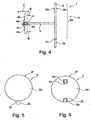
- FIG. 4 shows a side view and FIG. 5 a plan view from the direction A on the in FIG. 2 shown holding device 1, before it has been mounted.
- the holding device 1 comprises a plate 2, which consists of a circular support member 2a, a connection point 2c and a protruding thereon in the direction of the plate 2 tab 2b.
- the connection point 2c is designed as a weak point, so that the flap 2b is bendable with respect to the support part 2a.
- a threaded rod 3 fixedly connected to the support part 2a by this example is welded.
- the threaded rod 3 is preferably connected to the bearing part 2a, that this, as from FIG. 5 can be seen, not on the front side 2e, that is, the surface of the support member 2a protrudes.
- the holding device 1 also comprises a fastening part 4, configured in this embodiment as a tilting dowel, wherein the tilting dowel 4 comprises a bearing part 4a with internal thread, as well as at least one leg 4b which is pivotally connected to the bearing part 4a about a pivot axis 4c.
- the threaded rod 3 engages in the internal thread of the bearing part 4a, so that the bearing part 4a and thus the entire fastening part 4 during rotation of the threaded rod 3 along the Threaded rod 3 shifts.
- the tilting dowel 4 comprises two legs 4b, which are shown in an end position, and which are pivotable in the direction of movement B.
- the tilting dowel 4 comprises a spring 4e shown only dashed lines, selche the leg 4b automatically holds in the position shown.
- the holding device 1 can as off FIG. 3 can be fixed as follows to a grating 6: The tilting dowel 4 is pushed into a grid element into it, the legs 4b abut during support pouring on support or transverse bars 6a, 6b, and are therefore moved in the direction of movement B. As soon as the legs 4b have passed the carrying or transverse bars 6a, 6b, the legs 4b will return to the in FIG. 3 and FIG. 4 shown pivoted position back.
- the plate 2 is rotated as long as the rotation axis determined by the course of the threaded rod 3, until the plate 2, as from FIG. 2 seen, rests on the one surface of the grid 6, and until the legs 4b of the tilting dowel 4, as shown in FIG FIG. 3 can be seen on the opposite surface of the grid 6 abut.
- the tab 2b as shown FIG. 2 can be seen bent down so that the tab 2b comes to lie in a gap of the grating 6, so that the plate 2 is only in a very small angle range or no longer rotatable.
- the holding device 1 is thus connected against rotation with the grating 6.
- the indicator 5 can be attached to the surface of the support member 2a.
- the license plate 5 could also be applied to the support member 2a before attaching the holding device 1. In this case, during the attachment of the holding device 1, the support part 2a would have to be such be aligned that this has the desired orientation in its end position.
- leg 4b has an overall length which is longer than the diagonal D of support bar spacing 6d and bar spacing 6e. This ensures that the leg 4b can abut the grating 6 on both sides. It is also necessary that the diameter of the support member 2 a is greater than the support rod spacing 6 d or the cross bar spacing 6 e, to ensure that the support member 2 a does not fall through the gap of the grid 6 but rests against the surface of the grid 6.
- the tilting dowel 4 comprises two pivotable legs 4b.
- the tilting dowel 4 could also be designed such that it has only a single pivotable leg 4b, for example by the whole in FIG. 4 shown legs 4b is configured in one piece and is pivotable in the direction of movement C.
- FIG. 5 shows a support member 2a with a circular outer edge 2f and a radially projecting tab 2b, wherein the tab 2b extends over the bendable weak point 2c along a portion of the outer edge 2f.
- this subsection has the course of a pitch circle.
- FIG. 6 shows further possible embodiments and arrangements of the tab 2b, which as shown on a weaker formed connection point 2c is connected to the support part 2a, wherein the flap 2b is completely or at least partially disposed within the area enclosed by the outer edge 2f of the support member 2a surface.
- FIG. 6 shows below an embodiment in which the flap 2b is disposed at the edge of the support member 2a.
- FIG. 6 shows above an embodiment in which the flap 2b is disposed entirely within the surface of the support member 2a.
- the flap 2b is in each case bendable, as in FIG. 2 shown in a space of a grid 6 intervene.
- the support member 2a has a circular outer contour.
- the outer contour could also have other shapes, for example, quadrangular, square, polygonal or rounded shapes such as elliptical.
- the support part 2a could in particular have a polygonal outer edge 2f, for example a four, five, six, eight or sixteen corner outer edge 2f.
- the threaded rod 3 is arranged in the center or in the center of gravity of the support member 2a.
- the threaded rod 3 could also be arranged eccentrically with respect to the center or the center of gravity.
- the plate 2 is preferably made of a metallic sheet and advantageously has a thickness between 0.5 mm and 5 mm. Such a thickness has the advantage that the support part 2a, as shown in FIG. 2 seen, only slightly protrudes beyond the surface of the grid 6. Thus, there is no risk of tripping, if the grating 6 forms part of a walk-in surface.
- the Inventive holding device 1 also has the advantage that a rotation of the support member 2a due to the engaging in the space of the grating 6 tab 2b is not possible, so that it is ensured in the long term that the holding device 1 does not solve and maintains its position.
- the holding device 1 according to the invention has the advantage that the same holding device 1 can be securely fastened to gratings having different dimensions, and in particular having different carrier bar spacings or different transverse bar spacings.
- FIG. 7 shows a side view of another embodiment of a holding device 1, wherein the fastening part 4, in contrast to the in FIG. 4 illustrated embodiment, as a nut 4d, in particular a hex nut, and a washer 4f is configured, wherein the nut 4d is rotatably connected to the threaded rod.
- the holding device 1 can thus be fastened or loosened by turning the nut 4d and / or by rotating the plate 2, for example on a wire rack 6.
- FIG. 8 shows a plan view of a particularly advantageous holding device 1, which has in the center of the support member 2a a recessed into the surface recess 2g.
- the recess 2g is arranged concentrically or coaxially to the threaded rod extending.
- the recess is configured such that a tool head can engage in the recess to effect a torque on the plate to thereby rotate the plate.
- the recess is advantageously designed as a form elements for positive contact with a tool head to to engage the recess with the aid of a tool head and to cause a torque on the plate to thereby rotate the plate.
- the recess may be configured in a variety of forms, similar to screw heads, and for example as a slot, or as in FIG FIG.
- a tool head adapted to the recess for example, similar to a screwdriver, engages with the recess 2g to turn the plate 2 clockwise or anticlockwise, thereby either fixing or releasing the plate 2.
- the tool head is connected to a machine such as a drill or a cordless screwdriver, so that the holding device 1 according to the invention can be attached and released again particularly quickly and conveniently.
- the recess 2g forms an end face of the threaded rod 3, so that acting on the recess 2g tool head acts directly and directly on the threaded rod 3. This also ensures that the recess 2 g is arranged concentrically and coaxially with the threaded rod 3.
- a single recess 2g could be spaced apart from the center of the support member 2a and spaced circumferentially with respect to the center. It would then be necessary with respect to the arrangement of the wells 2g opposite ausgestalteter tool head, which can engage in all recesses 2g simultaneously, and which such is designed such that the plate 2 rotates when turning the tool head about the axis of the threaded rod 3.
- a first recess 2g could be as in FIG FIG. 8 may be arranged in the center of the support member 2a, and at least one further recess 2g spaced with respect to the center to be arranged.
- the recess 2g could also be designed as an internal thread.
- the tool head along an end portion of an external thread, which is configured equal to the internal thread of the recess 2g, so that the end portion of the tool head screwed into the recess 2g and preferably can be unscrewed again
- FIGS. 2 to 7 illustrated embodiments of holding devices 1 could with a like with the aid of FIG. 8 be described recess 2g be provided.
- the designed as a tilting dowel fixing part 4 has a leg 4b, whose overall length is designed to be longer than the diagonal D of support bar spacing 6d and cross bar spacing 6e.
- the diameter of the Support part 2a is designed larger than the support bar spacing 6d or the cross bar spacing 6e.
- the kit may include a plurality of holding devices 1, wherein the holding devices 1 different length leg 4b and / or different lengths threaded rods 3 includes.
- a kit has the advantage that the holding devices 1 can be fastened to latticeworks of very different design, wherein the support bar spacing and / or the crossbar spacing can vary within a wide range, and nevertheless a secure fastening of the holding devices 1 is possible.
Landscapes
- Physics & Mathematics (AREA)
- General Physics & Mathematics (AREA)
- Engineering & Computer Science (AREA)
- Theoretical Computer Science (AREA)
- Clamps And Clips (AREA)
- Vehicle Waterproofing, Decoration, And Sanitation Devices (AREA)
Description
Die Erfindung betrifft eine Haltevorrichtung für Kennzeichen. Die Erfindung betrifft weiter einen Bausatz umfassend eine Haltevorrichtung sowie zumindest ein Kennzeichen.The invention relates to a holding device for license plates. The invention further relates to a kit comprising a holding device and at least one indicator.
Gesetzgeber und Behörden fordern eindeutige Hinweise auf Gefahren und klar verständliche Anweisungen für Notsituationen. Dazu werden in der Praxis Anlagenkennzeichen oder Sicherheits- und Gesundheitskennzeichen verwendet. Mit Hilfe solcher Kennzeichen wird auf entsprechende Gefahren aufmerksam gemacht, oder werden beispielsweise Flucht- oder Rettungswege angezeigt. Solche Kennzeichen sind visuelle Darstellungen wie Schilder, welche an Anlagen oder in Gebäuden montiert werden. Solche Kennzeichen müssen einerseits an gut sichtbarer Stelle angeordnet sein, dürfen jedoch, insbesondere bei Kennzeichnung von Fluchtwegen, auf keinen Fall irgendwie hinderlich sein. Die Kennzeichen dürfen insbesondere keine Stolpergefahr bilden. Zudem muss gewährleistet sein, dass die Kennzeichen ihre Lage im Verlaufe der Zeit nicht verändert. Zudem sollen die Kennzeichen zuverlässig und kostengünstig angebracht werden können. Die Kennzeichen, insbesondere Sicherheitskennzeichen, sollen insbesondere an Gitterrösten, und insbesondere auch an Gitterrösten unterschiedlicher Grösse und Struktur, einfach angebracht werden können, um zum Beispiel Fluchtwege zu markieren.Legislators and authorities demand clear evidence of danger and clear instructions for emergency situations. For this purpose, plant codes or safety and health characteristics are used in practice. With the help of such markings attention is drawn to appropriate dangers, or are displayed, for example, escape or rescue routes. Such features are visual representations such as signs mounted on equipment or in buildings. On the one hand, such markings must be arranged in a clearly visible position, but in no case should they be a hindrance, in particular when marking escape routes. The license plates may in particular do not create a risk of tripping. It must also be ensured that the license plate does not change its position over time. In addition, the license plate should be reliable and inexpensive to install. The markings, in particular safety markings, should be able to be applied in a simple manner, in particular to latticed roasting, and in particular also to lattice roasters of different size and structure, in order, for example, to mark escape routes.
Das Dokument
Aufgabe der Erfindung ist es eine wirtschaftlich vorteilhaftere Haltevorrichtung für Kennzeichen, insbesondere für Sicherheitskennzeichen auszubilden.The object of the invention is to form an economically advantageous holding device for license plates, in particular for safety signs.
Diese Aufgabe wird gelöst mit einer Haltevorrichtung für ein Kennzeichen aufweisend die Merkmale von Anspruch 1. Die abhängigen Ansprüche 2 bis 13 betreffen weitere, vorteilhaft ausgestaltete Haltevorrichtungen.This object is achieved with a holding device for a license plate having the features of claim 1. The dependent claims 2 to 13 relate to further, advantageously designed holding devices.
Die Aufgabe wird weiter gelöst mit einem Bausatz aufweisend die Merkmale von Anspruch 14 oder 15.The object is further achieved with a kit having the features of claim 14 or 15.
Die Aufgabe wird insbesondere gelöst mit einer Haltevorrichtung umfassend eine Platte sowie eine senkrecht zur Platte verlaufende, mit der Platte fest verbundene Gewindestange, sowie umfassend ein Befestigungsteil mit einem Innengewinde, wobei das Befestigungsteil über das Innengewinde drehbar mit der Gewindestange verbunden ist, wobei die Platte aus einem Auflageteil sowie aus einer in Verlaufsrichtung der Platte verlaufenden Lasche besteht, wobei die Lasche knickbar mit dem Auflageteil verbunden ist, wobei das Auflageteil zwei Seiten aufweist, wobei die eine Seite mit der Gewindestange verbunden ist und wobei die andere Seite als Unterlage für ein Kennzeichen dient.The object is achieved in particular with a holding device comprising a plate and a perpendicular to the plate, with the plate fixedly connected threaded rod, and comprising a fastening part with an internal thread, wherein the fastening part is rotatably connected via the internal thread with the threaded rod, wherein the plate a support member as well as from a running in the direction of the plate flap, wherein the Tab is bendable connected to the support member, wherein the support member has two sides, wherein the one side is connected to the threaded rod and wherein the other side serves as a support for a license plate.
In einer besonders bevorzugten Ausgestaltung ist das Befestigungsteil als ein Kippdübel ausgestaltet, sodass eine äusserst einfache und schnelle Befestigung möglich ist.In a particularly preferred embodiment, the fastening part is designed as a tilting dowel, so that an extremely simple and fast attachment is possible.
In einer weiteren besonders bevorzugten Ausgestaltung umfasst die Platte auf der Seite, welche zum Anbringen des Kennzeichens bestimmt ist, eine vorteilhafterweise konzentrisch zur Gewindestange verlaufende Vertiefung. Die Vertiefung ist derart ausgestaltet, dass ein Werkzeugkopf in die Vertiefung eingreifen kann, um ein Drehmoment auf die Platte zu bewirken, um dadurch die Platte zu drehen. Dies ermöglicht ein besonders einfaches und effizientes Befestigen der Haltevorrichtung, indem beispielsweise ein Maschinen betriebener Werkzeugkopf, beispielsweise ein Akkubohrer mit einem eingespannten Werkzeugkopf, wie zum Beispiel einem Sechskantwerkzeug, verwendet wird. In einem ersten Schritt wird der Werkzeugkopf in die Vertiefung eingeführt und in einem zweiten Schritt der Akkubohrer betätigt, sodass die Platte gedreht wird und die Gewindestange mit dem Befestigungsteil verbunden wird, oder das Befestigungsteil angezogen wird, oder die Platte vom Befestigungsteil gelöst wird. Die Vertiefung ist derart ausgestaltet, dass kein Teil über die Oberfläche des Auflageteils 2a vorsteht. In einer weiteren vorteilhaften Ausgestaltung ist die Vertiefung als ein Innengewinde ausgestaltet. Zum Befestigen einer Haltevorrichtung mit als Innengewinde ausgestalteter Vertiefung wird vorteilhafterweise eine Werkzeugkopf verwendet, der ein zur Vertiefung gegengleich ausgestaltetes Aussengewinde aufweist, sodass beim Befestigen der Haltevorrichtung in einem ersten Verfahrensschritt der Stirnabschnitt des Werkzeugkopfs in die Vertiefung hineingeschraubt wird, dass in einem zweiten Verfahrensschritt die gesamte Haltevorrichtung rotiert wird durch den einwirkenden Werkzeugkopf, bis die Haltevorrichtung befestigt ist, z.B. an einem Gitterrost. In einem anschliessenden, dritten Verfahrensschritt wird die Drehrichtung des Werkzeugkopfs gedreht, sodass der Werkzeugkopf in entgegengesetzter Richtung gedreht wird, sodass der Werkzeugkopf aus der Verhiefung herausgeschraubt wird bis der Werkzeugkopf von der Haltevorrichtung wieder getrennt ist. Diese Ausgestaltung weist den Vorteil auf, dass die Haltevorrichtung während dem Befestigen sicher mit dem Werkzeugkopf verbunden ist. Im Gegensatz dazu besteht beispielsweise bei einem als Sechskantwerkzeug ausgestalteten Werkzeugkopf die Gefahr, dass sich die Haltevorrichtung während dem Befestigen vom Werkzeugkopf lösen könnte.In a further particularly preferred embodiment, the plate on the side, which is intended for attaching the plate, advantageously a concentric to the threaded rod extending recess. The recess is configured such that a tool head can engage in the recess to effect a torque on the plate to thereby rotate the plate. This allows a particularly simple and efficient fastening of the holding device, for example by using a machine-operated tool head, for example a cordless drill with a clamped tool head, such as a hexagonal tool. In a first step, the tool head is inserted into the recess and actuated in a second step of the cordless drill, so that the plate is rotated and the threaded rod is connected to the fastening part, or the fastening part is tightened, or the plate is released from the fastening part. The recess is designed such that no part projects beyond the surface of the
Die erfindungsgemässe Haltevorrichtung ist zur Befestigung irgendwelcher Kennzeichen geeignet, wobei die Kennzeichen zum Beispiel Bilder, Piktogramme und/oder Beschriftungen umfassen können. Diese Kennzeichen können an der Oberfläche der Platte befestigt werden, oder bilden Teil der Platte, indem die Kennzeichen z.B. in die Platte eingraviert sind, oder auf der Oberfläche der Platte angebracht sind.The holding device according to the invention is suitable for attaching any license plates, wherein the license plates may include, for example, images, pictograms and / or labels. These markings can be fixed to the surface of the plate, or form part of the plate by having the markings e.g. are engraved in the plate, or mounted on the surface of the plate.
Die erfindungsgemässe Haltevorrichtung weist insbesondere den Vorteil auf, dass diese an Gitterrösten, wie diese in Industrieanlagen häufig eingesetzt werden, auf einfache Weise und verdrehsicher befestigt werden kann. Die erfindungsgemässe Haltevorrichtung kann an einer Vielzahl von unterschiedlich ausgestalteten Gitterrösten befestigt werden, wobei sich diese unterschiedlichen Gitterroste insbesondere bezüglich Tiefe und/oder Maschenweite zwischen den Tragstäben beziehungsweise den Querstäben unterscheiden. Somit kann die erfindungsgemässe Haltevorrichtung an einer Vielzahl von geometrisch unterschiedlich gestalteten Gitterrösten problemlos montiert werden. Die erfindungsgemässe Haltevorrichtung weist bei einer Befestigung an einem horizontal verlaufenden Gitterrost den Vorteil auf, dass die Haltevorrichtung nur sehr geringfügig über den Gitterrost vorsteht, sodass die Haltevorrichtung kein Stolperhindernis darstellt. Auf Grund der Verdrehsicherung der Haltevorrichtung ist zudem langfristig gewährleistet, dass es nicht möglich ist, dass sich die Haltevorrichtung selbsttätig lösen und/oder verdrehen kann, oder dass die Haltevorrichtung im Verlaufe der Zeit weiter als unbedingt nötig über dem Gitterrost vorsteht. Dadurch ist eine langfristig sichere und zuverlässige Verwendung der Haltevorrichtung beziehungsweise des Kennzeichens möglich. Dies ist besonders vorteilhaft, wenn die Haltevorrichtung im Zusammenhang mit Sicherheitskennzeichen verwendet wird, weil bezüglich der dauerhaften, gefahrlosen und sicheren Anordnung von Sicherheitskennzeichen erhöhte Vorschriften bestehen.In particular, the holding device according to the invention has the advantage that it can be fastened to latticed roasting in a simple manner and against rotation, as are frequently used in industrial plants. The inventive holding device can be attached to a variety of differently designed lattice roasters, with these different gratings differ in particular with respect to depth and / or mesh size between the support rods or the transverse rods. Thus, the inventive holding device can be easily mounted on a variety of geometrically differently designed lattice roasting. When mounted on a horizontally extending grate, the holding device according to the invention has the advantage that the holding device protrudes only very slightly over the grate, so that the holding device does not present a stumbling block. Due to the anti-rotation of the holding device is also long-term ensured that it is not possible that the holding device can solve and / or rotate automatically, or that the holding device in the course of time further than necessarily beyond the grating protrudes. As a result, a long-term safe and reliable use of the holding device or the license plate is possible. This is particularly advantageous if the holding device is used in conjunction with safety markings, because there are increased regulations with regard to the permanent, safe and secure arrangement of safety markings.
Die zur Erläuterung der Ausführungsbeispiele verwendeten Zeichnungen zeigen:
- Fig. 1
- eine perspektivische Ansicht eines Gitterrostes;
- Fig. 2
- der in
Figur 1 dargestellte Gitterrost mit daran befestigter Haltevorrichtung; - Fig. 3
- die Anordnung gemäss
Figur 2 - Fig. 4
- eine Seitenansicht der Haltevorrichtung;
- Fig. 5
- eine Draufsicht auf die Haltevorrichtung aus Blickrichtung A;
- Fig. 6
- eine Draufsicht auf ein weiteres Ausführungsbeispiel einer Haltevorrichtung;
- Fig. 7
- eine Seitenansicht eines weiteren Ausführungsbeispiels einer Haltevorrichtung;
- Fig. 8
- eine Draufsicht auf eine weitere Haltevorrichtung mit an der Oberfläche eingelassener Vertiefung.
- Fig. 1
- a perspective view of a grid;
- Fig. 2
- the in
FIG. 1 illustrated grid with attached holding device; - Fig. 3
- the arrangement according to
FIG. 2 in a view from below; - Fig. 4
- a side view of the holding device;
- Fig. 5
- a plan view of the holding device from the direction A;
- Fig. 6
- a plan view of another embodiment of a holding device;
- Fig. 7
- a side view of another embodiment of a holding device;
- Fig. 8
- a plan view of another holding device with recessed on the surface recess.
Grundsätzlich sind in den Zeichnungen gleiche Teile mit gleichen Bezugszeichen versehen.Basically, the same parts are given the same reference numerals in the drawings.
Um eine sichere Verbindung der Haltevorrichtung 1 mit dem Gitterrost 6 zu gewährleisten ist es wie aus den
Im dargestellten Ausführungsbeispiel umfasst der Kippdübel 4 zwei schwenkbare Schenkel 4b. Der Kippdübel 4 könnte jedoch auch derart ausgestaltet sein, dass dieser nur einen einzigen schwenkbaren Schenkel 4b aufweist, zum Beispiel indem der ganze in
Im dargestellten Ausführungsbeispiel weist das Auflageteil 2a eine kreisförmige Aussenkontur auf. Die Aussenkontur könnte jedoch auch andere Formen aufweisen, zum Beispiel viereckig, quadratisch, vieleckig oder abgerundete Formen wie elliptisch. Das Auflageteil 2a könnte insbesondere eine vieleckig verlaufende Aussenkante 2f aufweisen, beispielsweise eine vier-, fünf-, sechs-, acht- oder sechzehneckige Aussenkante 2f.In the illustrated embodiment, the
Vorteilhafterweise ist die Gewindestange 3 im Zentrum oder im Schwerpunkt des Auflageteils 2a angeordnet. Die Gewindestange 3 könnte jedoch auch exzentrisch bezüglich dem Zentrum oder dem Schwerpunkt angeordnet sein.Advantageously, the threaded
Die Platte 2 besteht vorzugsweise aus einem metallischen Blech und weist vorteilhafterweise eine Dicke zwischen 0,5 mm und 5 mm auf. Eine derartige Dicke weist den Vorteil auf, dass das Auflageteil 2a, wie aus
In einer vorteilhaften Ausgestaltung bildet die Vertiefung 2g eine Stirnseite der Gewindestange 3, sodass ein an der Vertiefung 2g angreifender Werkzeugkopf unmittelbar und direkt auf die Gewindestange 3 wirkt. Damit ist auch sichergestellt, dass die Vertiefung 2g konzentrisch und koaxial zur Gewindestange 3 angeordnet ist.In an advantageous embodiment, the
Bei einer weiteren Ausführungsform könnte eine einzige Vertiefung 2g und vorzugsweise eine Mehrzahl von Vertiefungen 2g beabstandet bezüglich dem Zentrum des Auflageteils 2a und gegenseitig in Umfangsrichtung bezüglich dem Zentrum beabstandet angeordnet sein. Es wäre denn ein bezüglich der Anordnung der Vertiefungen 2g gegengleich ausgestalteter Werkzeugkopf erforderlich, der in alle Vertiefungen 2g gleichzeitig eingreifen kann, und welcher derart ausgestaltet ist, dass sich die Platte 2 beim drehen des Werkzeugkopfes um die Achse der Gewindestange 3 dreht. In einer weiteren möglichen Ausführungsform könnte eine erste Vertiefung 2g wie in
In einer weiteren vorteilhaften Ausgestaltung könnte die Vertiefung 2g auch als ein Innengewinde ausgestaltet sein. In einer besonders vorteilhaften Ausgestaltung umfasst der Werkzeugkopf entlang eines Stirnabschnittes ein Aussengewinde, das gegengleich zum Innengewinde der Vertiefung 2g ausgestaltet ist, sodass der Stirnabschnitt des Werkzeugkopfs in die Vertiefung 2g hineingeschraubt und vorzugsweise auch wieder herausgeschraubt werden kannIn a further advantageous embodiment, the
Jede der in den
Besonders vorteilhaft ist ein Bausatz zum Anbringen eines Kennzeichens 5 an einem Gitterrost 6, wobei der Gitterrost 6 Tragstäbe 6a und Querstäbe 6b umfasst, und wobei der Gitterrost 6 einen Tragstababstand 6 und einen Querstababstand 6e aufweist, wobei der Bausatz zumindest ein und vorzugsweise eine Mehrzahl von Kennzeichen 5 sowie zumindest eine erfindungsgemässe Haltevorrichtung 1 umfasst. Das als Kippdübel ausgestaltete Befestigungsteil 4 weist einen Schenkel 4b aufweist, dessen Gesamtlänge länger ausgestaltet ist als die Diagonale D von Tragstababstand 6d und Querstababstand 6e. Der Durchmesser des Auflageteils 2a ist grösser ausgestaltet als der Tragstababstand 6d oder der Querstababstand 6e. In einer weiteren vorteilhaften Ausgestaltung kann der Bausatz eine Mehrzahl von Haltevorrichtungen 1 umfassen, wobei die Haltevorrichtungen 1 unterschiedlich lange Schenkel 4b und/oder unterschiedlich lange Gewindestangen 3 umfasst. Ein derartiger Bausatz weist den Vorteil auf, dass die Haltevorrichtungen 1 an unterschiedlichst ausgestalteten Gitterrösten befestig werden kann, wobei der Tragstababstand und/oder der Querstababstand in einem grossen Bereich variieren kann, und trotzdem ein sicheres Befestigen der Haltevorrichtungen 1 möglich ist.Particularly advantageous is a kit for attaching a
Claims (15)
- Mounting device (1) for a sign (5), comprising a plate (2) and a threaded rod (3) which runs perpendicularly to the plate (2) and is fixedly connected to the plate (2), and comprising a fastening part (4) having an internal thread (4a), characterized in that the fastening part (4) by way of the internal thread (4a) is rotatably connected to the threaded rod (3), wherein the plate (2) is composed of a support part (2a) and of a tab (2b) which runs in the primary direction of the plate (2), wherein the tab (2b) by way of a weak spot (2c) which is capable of buckling is connected to the support part (2a), wherein the support part (2a) has two sides (2d, 2e), wherein the one side (2d) is connected to the threaded rod (3), and wherein the other side (2e) serves as a support face for the sign (5).
- Mounting device (1) according to Claim 1, characterized in that the fastening part (4) is designed as a toggle dowel.
- Mounting device (1) according to Claim 1, characterized in that the fastening part (4) is designed as a nut.
- Mounting device (1) according to Claim 2 or 3, characterized in that the tab (2b) in the primary direction of the plate (2) projects beyond the support part (2a).
- Mounting device (1) according to Claim 4, characterized in that the support part (2a) has an external edge (2f), and that the weak spot (2c) which is capable of buckling is connected to the external edge (2f) and to the projecting tab (2b) such that the weak spot (2c) runs along a part-portion of the external edge (2f).
- Mounting device (1) according to Claim 2 or 3, characterized in that the tab (2b) is disposed so as to run within the support part (2a).
- Mounting device (1) according to one of Claims 2 to 6, characterized in that the support part (2a) is designed so as to be circular, and that the threaded rod (3) in the centre of the support part (2a) is connected to the latter.
- Mounting device (1) according to one of Claims 2 to 6, characterized in that the support part (2a) is designed so as to be polygonal, in particular rectangular, and that the threaded rod (3) in the centre of the support part (2a) is connected to the latter.
- Mounting device (1) according to one of Claims 7 and 8, characterized in that the side (2e) serving as a support face for the sign has a depression (2g), wherein the depression (2g) is designed in such a manner that a tool head may engage in the depression (2g) in order for a torque to act on the plate (2).
- Mounting device (1) according to Claim 9, characterized in that the depression (2g) is disposed so as to be concentric with the threaded rod (3).
- Mounting device according to Claim 10, characterized in that the depression (2g) is designed as an internal thread.
- Mounting device (1) according to one of the preceding claims, characterized in that the threaded rod (3) is welded to the plate (2).
- Mounting device (1) according to Claim 2, characterized in that the toggle dowel (4) is designed as a sprung toggle dowel.
- Construction kit for attaching a sign (5) to a grate (6), wherein the grate (6) comprises support bars (6a) and transverse bars (6b), and wherein the grate (6) has a support-bar spacing (6d) and a transverse-bar spacing (6e), said construction kit comprising at least one sign (5) and a mounting device (1) according to one of Claims 1 to 13, wherein the fastening part (4) has a bearing part (4b), the total length of which is designed to be longer than the diagonal (D) between the support-bar spacing (6d) and the transverse-bar spacing (6e), and wherein the diameter of the support part (2a) is designed to be larger than the support-bar spacing (6b) or the transverse-bar spacing (6e).
- Construction kit according to Claim 14, characterized in that the fastening part (4) is designed as a toggle dowel, and that the bearing part (4b) is designed as a leg of the toggle dowel.
Applications Claiming Priority (1)
| Application Number | Priority Date | Filing Date | Title |
|---|---|---|---|
| CH9942013A CH708085A2 (en) | 2013-05-22 | 2013-05-22 | Holder for license plate and kit comprising such a holding device. |
Publications (2)
| Publication Number | Publication Date |
|---|---|
| EP2806417A1 EP2806417A1 (en) | 2014-11-26 |
| EP2806417B1 true EP2806417B1 (en) | 2016-08-17 |
Family
ID=50792366
Family Applications (1)
| Application Number | Title | Priority Date | Filing Date |
|---|---|---|---|
| EP14169324.2A Not-in-force EP2806417B1 (en) | 2013-05-22 | 2014-05-21 | Holding device for labels, and kit comprising such a holding device |
Country Status (2)
| Country | Link |
|---|---|
| EP (1) | EP2806417B1 (en) |
| CH (1) | CH708085A2 (en) |
Family Cites Families (3)
| Publication number | Priority date | Publication date | Assignee | Title |
|---|---|---|---|---|
| FR2668283B1 (en) * | 1990-10-23 | 1993-04-02 | Bertrand Dominique | TRACKING PLATE. |
| US5568785A (en) * | 1995-08-03 | 1996-10-29 | Hazen; Hallie W. | Utility marking device |
| FR2896970A1 (en) * | 2006-02-03 | 2007-08-10 | Pierre Hunault | FIXING DEVICE FOR FLOWER POT |
-
2013
- 2013-05-22 CH CH9942013A patent/CH708085A2/en not_active Application Discontinuation
-
2014
- 2014-05-21 EP EP14169324.2A patent/EP2806417B1/en not_active Not-in-force
Also Published As
| Publication number | Publication date |
|---|---|
| EP2806417A1 (en) | 2014-11-26 |
| CH708085A2 (en) | 2014-11-28 |
Similar Documents
| Publication | Publication Date | Title |
|---|---|---|
| EP2505449B1 (en) | Thread carrier with holding block | |
| DE1500829A1 (en) | Rotatable device | |
| DE69835759T2 (en) | AUTOMATIC MOUNTING DEVICE FOR SCREWS | |
| WO2016012081A1 (en) | Fastener for a mounting rail | |
| DE2053443B2 (en) | Building | |
| DE202013102220U1 (en) | Holding device for license plate and kit comprising such a holding device | |
| DE1625382A1 (en) | Fastening device | |
| EP2806417B1 (en) | Holding device for labels, and kit comprising such a holding device | |
| DE202011110394U1 (en) | screw | |
| DE1816856A1 (en) | Clamp strap to hold fuel elements in - transport containers | |
| EP3402993B1 (en) | Mounting assembly with a mounting rail and protruding retaining nut | |
| DE102005059523A1 (en) | Nut and/or connecting device for positioning e.g. in recess or slot of component, has retainer comprising clamping part protruding over upper side of nut in unloaded condition | |
| CH714926A2 (en) | Connecting element for mounting a side guard and side protection system. | |
| DE102013214597B3 (en) | Shower basket mounted on shower wall has clamping element that is adjustable from release position to clamping position to clamp shower basket in direction of stop on support rod | |
| DE2000449A1 (en) | Nut for fastening in a carrier opening | |
| DE1059722B (en) | Bracket for polygonal nuts, screw heads, etc. like | |
| DE1163519B (en) | Height-adjustable suspension device for a false ceiling | |
| DE102009034427B4 (en) | Holding plate for the longitudinally adjustable mounting of rod parts and device using the holding plate | |
| DE19825132A1 (en) | Bolt thread for screw connection with bolt and nut | |
| DE102007041403B4 (en) | Clamping screw with gravity lock | |
| DE549331C (en) | Corner connection piece for a frame composed of individual strips for lighting bodies consisting of square and triangular glass plates of a square, traffic light-like shape | |
| DE3434012A1 (en) | Wire-clamping device | |
| DE202013101651U1 (en) | clamping device | |
| AT334053B (en) | ANCHORING DEVICE | |
| CH483136A (en) | Device for clamping electrical devices to mounting rails |
Legal Events
| Date | Code | Title | Description |
|---|---|---|---|
| PUAI | Public reference made under article 153(3) epc to a published international application that has entered the european phase |
Free format text: ORIGINAL CODE: 0009012 |
|
| 17P | Request for examination filed |
Effective date: 20140521 |
|
| AK | Designated contracting states |
Kind code of ref document: A1 Designated state(s): AL AT BE BG CH CY CZ DE DK EE ES FI FR GB GR HR HU IE IS IT LI LT LU LV MC MK MT NL NO PL PT RO RS SE SI SK SM TR |
|
| AX | Request for extension of the european patent |
Extension state: BA ME |
|
| RBV | Designated contracting states (corrected) |
Designated state(s): AL AT BE BG CH CY CZ DE DK EE ES FI FR GB GR HR HU IE IS IT LI LT LU LV MC MK MT NL NO PL PT RO RS SE SI SK SM TR |
|
| R17P | Request for examination filed (corrected) |
Effective date: 20150526 |
|
| GRAP | Despatch of communication of intention to grant a patent |
Free format text: ORIGINAL CODE: EPIDOSNIGR1 |
|
| INTG | Intention to grant announced |
Effective date: 20160112 |
|
| INTG | Intention to grant announced |
Effective date: 20160201 |
|
| INTG | Intention to grant announced |
Effective date: 20160223 |
|
| GRAS | Grant fee paid |
Free format text: ORIGINAL CODE: EPIDOSNIGR3 |
|
| GRAA | (expected) grant |
Free format text: ORIGINAL CODE: 0009210 |
|
| AK | Designated contracting states |
Kind code of ref document: B1 Designated state(s): AL AT BE BG CH CY CZ DE DK EE ES FI FR GB GR HR HU IE IS IT LI LT LU LV MC MK MT NL NO PL PT RO RS SE SI SK SM TR |
|
| REG | Reference to a national code |
Ref country code: GB Ref legal event code: FG4D Free format text: NOT ENGLISH |
|
| REG | Reference to a national code |
Ref country code: CH Ref legal event code: EP |
|
| REG | Reference to a national code |
Ref country code: IE Ref legal event code: FG4D Free format text: LANGUAGE OF EP DOCUMENT: GERMAN |
|
| REG | Reference to a national code |
Ref country code: AT Ref legal event code: REF Ref document number: 821740 Country of ref document: AT Kind code of ref document: T Effective date: 20160915 |
|
| REG | Reference to a national code |
Ref country code: DE Ref legal event code: R096 Ref document number: 502014001249 Country of ref document: DE |
|
| REG | Reference to a national code |
Ref country code: NL Ref legal event code: MP Effective date: 20160817 |
|
| REG | Reference to a national code |
Ref country code: LT Ref legal event code: MG4D |
|
| PG25 | Lapsed in a contracting state [announced via postgrant information from national office to epo] |
Ref country code: NO Free format text: LAPSE BECAUSE OF FAILURE TO SUBMIT A TRANSLATION OF THE DESCRIPTION OR TO PAY THE FEE WITHIN THE PRESCRIBED TIME-LIMIT Effective date: 20161117 Ref country code: NL Free format text: LAPSE BECAUSE OF FAILURE TO SUBMIT A TRANSLATION OF THE DESCRIPTION OR TO PAY THE FEE WITHIN THE PRESCRIBED TIME-LIMIT Effective date: 20160817 Ref country code: FI Free format text: LAPSE BECAUSE OF FAILURE TO SUBMIT A TRANSLATION OF THE DESCRIPTION OR TO PAY THE FEE WITHIN THE PRESCRIBED TIME-LIMIT Effective date: 20160817 Ref country code: RS Free format text: LAPSE BECAUSE OF FAILURE TO SUBMIT A TRANSLATION OF THE DESCRIPTION OR TO PAY THE FEE WITHIN THE PRESCRIBED TIME-LIMIT Effective date: 20160817 Ref country code: HR Free format text: LAPSE BECAUSE OF FAILURE TO SUBMIT A TRANSLATION OF THE DESCRIPTION OR TO PAY THE FEE WITHIN THE PRESCRIBED TIME-LIMIT Effective date: 20160817 Ref country code: IT Free format text: LAPSE BECAUSE OF FAILURE TO SUBMIT A TRANSLATION OF THE DESCRIPTION OR TO PAY THE FEE WITHIN THE PRESCRIBED TIME-LIMIT Effective date: 20160817 Ref country code: LT Free format text: LAPSE BECAUSE OF FAILURE TO SUBMIT A TRANSLATION OF THE DESCRIPTION OR TO PAY THE FEE WITHIN THE PRESCRIBED TIME-LIMIT Effective date: 20160817 |
|
| PG25 | Lapsed in a contracting state [announced via postgrant information from national office to epo] |
Ref country code: LV Free format text: LAPSE BECAUSE OF FAILURE TO SUBMIT A TRANSLATION OF THE DESCRIPTION OR TO PAY THE FEE WITHIN THE PRESCRIBED TIME-LIMIT Effective date: 20160817 Ref country code: ES Free format text: LAPSE BECAUSE OF FAILURE TO SUBMIT A TRANSLATION OF THE DESCRIPTION OR TO PAY THE FEE WITHIN THE PRESCRIBED TIME-LIMIT Effective date: 20160817 Ref country code: PL Free format text: LAPSE BECAUSE OF FAILURE TO SUBMIT A TRANSLATION OF THE DESCRIPTION OR TO PAY THE FEE WITHIN THE PRESCRIBED TIME-LIMIT Effective date: 20160817 Ref country code: PT Free format text: LAPSE BECAUSE OF FAILURE TO SUBMIT A TRANSLATION OF THE DESCRIPTION OR TO PAY THE FEE WITHIN THE PRESCRIBED TIME-LIMIT Effective date: 20161219 Ref country code: SE Free format text: LAPSE BECAUSE OF FAILURE TO SUBMIT A TRANSLATION OF THE DESCRIPTION OR TO PAY THE FEE WITHIN THE PRESCRIBED TIME-LIMIT Effective date: 20160817 Ref country code: GR Free format text: LAPSE BECAUSE OF FAILURE TO SUBMIT A TRANSLATION OF THE DESCRIPTION OR TO PAY THE FEE WITHIN THE PRESCRIBED TIME-LIMIT Effective date: 20161118 |
|
| PG25 | Lapsed in a contracting state [announced via postgrant information from national office to epo] |
Ref country code: RO Free format text: LAPSE BECAUSE OF FAILURE TO SUBMIT A TRANSLATION OF THE DESCRIPTION OR TO PAY THE FEE WITHIN THE PRESCRIBED TIME-LIMIT Effective date: 20160817 Ref country code: EE Free format text: LAPSE BECAUSE OF FAILURE TO SUBMIT A TRANSLATION OF THE DESCRIPTION OR TO PAY THE FEE WITHIN THE PRESCRIBED TIME-LIMIT Effective date: 20160817 |
|
| REG | Reference to a national code |
Ref country code: DE Ref legal event code: R097 Ref document number: 502014001249 Country of ref document: DE |
|
| PG25 | Lapsed in a contracting state [announced via postgrant information from national office to epo] |
Ref country code: DK Free format text: LAPSE BECAUSE OF FAILURE TO SUBMIT A TRANSLATION OF THE DESCRIPTION OR TO PAY THE FEE WITHIN THE PRESCRIBED TIME-LIMIT Effective date: 20160817 Ref country code: SM Free format text: LAPSE BECAUSE OF FAILURE TO SUBMIT A TRANSLATION OF THE DESCRIPTION OR TO PAY THE FEE WITHIN THE PRESCRIBED TIME-LIMIT Effective date: 20160817 Ref country code: SK Free format text: LAPSE BECAUSE OF FAILURE TO SUBMIT A TRANSLATION OF THE DESCRIPTION OR TO PAY THE FEE WITHIN THE PRESCRIBED TIME-LIMIT Effective date: 20160817 Ref country code: CZ Free format text: LAPSE BECAUSE OF FAILURE TO SUBMIT A TRANSLATION OF THE DESCRIPTION OR TO PAY THE FEE WITHIN THE PRESCRIBED TIME-LIMIT Effective date: 20160817 Ref country code: BG Free format text: LAPSE BECAUSE OF FAILURE TO SUBMIT A TRANSLATION OF THE DESCRIPTION OR TO PAY THE FEE WITHIN THE PRESCRIBED TIME-LIMIT Effective date: 20161117 |
|
| PLBE | No opposition filed within time limit |
Free format text: ORIGINAL CODE: 0009261 |
|
| STAA | Information on the status of an ep patent application or granted ep patent |
Free format text: STATUS: NO OPPOSITION FILED WITHIN TIME LIMIT |
|
| 26N | No opposition filed |
Effective date: 20170518 |
|
| PG25 | Lapsed in a contracting state [announced via postgrant information from national office to epo] |
Ref country code: LU Free format text: LAPSE BECAUSE OF NON-PAYMENT OF DUE FEES Effective date: 20170531 Ref country code: SI Free format text: LAPSE BECAUSE OF FAILURE TO SUBMIT A TRANSLATION OF THE DESCRIPTION OR TO PAY THE FEE WITHIN THE PRESCRIBED TIME-LIMIT Effective date: 20160817 |
|
| REG | Reference to a national code |
Ref country code: CH Ref legal event code: PL |
|
| PG25 | Lapsed in a contracting state [announced via postgrant information from national office to epo] |
Ref country code: MC Free format text: LAPSE BECAUSE OF FAILURE TO SUBMIT A TRANSLATION OF THE DESCRIPTION OR TO PAY THE FEE WITHIN THE PRESCRIBED TIME-LIMIT Effective date: 20160817 |
|
| REG | Reference to a national code |
Ref country code: IE Ref legal event code: MM4A |
|
| PG25 | Lapsed in a contracting state [announced via postgrant information from national office to epo] |
Ref country code: CH Free format text: LAPSE BECAUSE OF NON-PAYMENT OF DUE FEES Effective date: 20170531 Ref country code: LI Free format text: LAPSE BECAUSE OF NON-PAYMENT OF DUE FEES Effective date: 20170531 |
|
| REG | Reference to a national code |
Ref country code: FR Ref legal event code: ST Effective date: 20180131 |
|
| PG25 | Lapsed in a contracting state [announced via postgrant information from national office to epo] |
Ref country code: LU Free format text: LAPSE BECAUSE OF NON-PAYMENT OF DUE FEES Effective date: 20170521 |
|
| REG | Reference to a national code |
Ref country code: BE Ref legal event code: MM Effective date: 20170531 |
|
| PG25 | Lapsed in a contracting state [announced via postgrant information from national office to epo] |
Ref country code: IE Free format text: LAPSE BECAUSE OF NON-PAYMENT OF DUE FEES Effective date: 20170521 |
|
| PG25 | Lapsed in a contracting state [announced via postgrant information from national office to epo] |
Ref country code: FR Free format text: LAPSE BECAUSE OF NON-PAYMENT OF DUE FEES Effective date: 20170531 |
|
| PGFP | Annual fee paid to national office [announced via postgrant information from national office to epo] |
Ref country code: DE Payment date: 20180522 Year of fee payment: 5 |
|
| PG25 | Lapsed in a contracting state [announced via postgrant information from national office to epo] |
Ref country code: BE Free format text: LAPSE BECAUSE OF NON-PAYMENT OF DUE FEES Effective date: 20170531 |
|
| PG25 | Lapsed in a contracting state [announced via postgrant information from national office to epo] |
Ref country code: MT Free format text: LAPSE BECAUSE OF FAILURE TO SUBMIT A TRANSLATION OF THE DESCRIPTION OR TO PAY THE FEE WITHIN THE PRESCRIBED TIME-LIMIT Effective date: 20160817 |
|
| PG25 | Lapsed in a contracting state [announced via postgrant information from national office to epo] |
Ref country code: AL Free format text: LAPSE BECAUSE OF FAILURE TO SUBMIT A TRANSLATION OF THE DESCRIPTION OR TO PAY THE FEE WITHIN THE PRESCRIBED TIME-LIMIT Effective date: 20160817 |
|
| GBPC | Gb: european patent ceased through non-payment of renewal fee |
Effective date: 20180521 |
|
| PG25 | Lapsed in a contracting state [announced via postgrant information from national office to epo] |
Ref country code: GB Free format text: LAPSE BECAUSE OF NON-PAYMENT OF DUE FEES Effective date: 20180521 |
|
| PG25 | Lapsed in a contracting state [announced via postgrant information from national office to epo] |
Ref country code: HU Free format text: LAPSE BECAUSE OF FAILURE TO SUBMIT A TRANSLATION OF THE DESCRIPTION OR TO PAY THE FEE WITHIN THE PRESCRIBED TIME-LIMIT; INVALID AB INITIO Effective date: 20140521 |
|
| PG25 | Lapsed in a contracting state [announced via postgrant information from national office to epo] |
Ref country code: CY Free format text: LAPSE BECAUSE OF FAILURE TO SUBMIT A TRANSLATION OF THE DESCRIPTION OR TO PAY THE FEE WITHIN THE PRESCRIBED TIME-LIMIT Effective date: 20160817 |
|
| PG25 | Lapsed in a contracting state [announced via postgrant information from national office to epo] |
Ref country code: MK Free format text: LAPSE BECAUSE OF FAILURE TO SUBMIT A TRANSLATION OF THE DESCRIPTION OR TO PAY THE FEE WITHIN THE PRESCRIBED TIME-LIMIT Effective date: 20160817 |
|
| REG | Reference to a national code |
Ref country code: DE Ref legal event code: R119 Ref document number: 502014001249 Country of ref document: DE |
|
| PG25 | Lapsed in a contracting state [announced via postgrant information from national office to epo] |
Ref country code: TR Free format text: LAPSE BECAUSE OF FAILURE TO SUBMIT A TRANSLATION OF THE DESCRIPTION OR TO PAY THE FEE WITHIN THE PRESCRIBED TIME-LIMIT Effective date: 20160817 |
|
| PG25 | Lapsed in a contracting state [announced via postgrant information from national office to epo] |
Ref country code: DE Free format text: LAPSE BECAUSE OF NON-PAYMENT OF DUE FEES Effective date: 20191203 |
|
| PG25 | Lapsed in a contracting state [announced via postgrant information from national office to epo] |
Ref country code: IS Free format text: LAPSE BECAUSE OF FAILURE TO SUBMIT A TRANSLATION OF THE DESCRIPTION OR TO PAY THE FEE WITHIN THE PRESCRIBED TIME-LIMIT Effective date: 20161217 |
|
| REG | Reference to a national code |
Ref country code: AT Ref legal event code: MM01 Ref document number: 821740 Country of ref document: AT Kind code of ref document: T Effective date: 20190521 |
|
| PG25 | Lapsed in a contracting state [announced via postgrant information from national office to epo] |
Ref country code: AT Free format text: LAPSE BECAUSE OF NON-PAYMENT OF DUE FEES Effective date: 20190521 |