EP2806319B1 - Logiciel de configuration et procédé d'élaboration de données de configuration et d'un programme PLC pour un appareil de commande et/ou de protection comportant une commande de stockage programmable pour la technologie de moyenne ou haute tension - Google Patents
Logiciel de configuration et procédé d'élaboration de données de configuration et d'un programme PLC pour un appareil de commande et/ou de protection comportant une commande de stockage programmable pour la technologie de moyenne ou haute tension Download PDFInfo
- Publication number
- EP2806319B1 EP2806319B1 EP14305777.6A EP14305777A EP2806319B1 EP 2806319 B1 EP2806319 B1 EP 2806319B1 EP 14305777 A EP14305777 A EP 14305777A EP 2806319 B1 EP2806319 B1 EP 2806319B1
- Authority
- EP
- European Patent Office
- Prior art keywords
- plc
- program
- software
- data
- configuration
- Prior art date
- Legal status (The legal status is an assumption and is not a legal conclusion. Google has not performed a legal analysis and makes no representation as to the accuracy of the status listed.)
- Active
Links
Images


Classifications
-
- G—PHYSICS
- G05—CONTROLLING; REGULATING
- G05B—CONTROL OR REGULATING SYSTEMS IN GENERAL; FUNCTIONAL ELEMENTS OF SUCH SYSTEMS; MONITORING OR TESTING ARRANGEMENTS FOR SUCH SYSTEMS OR ELEMENTS
- G05B19/00—Programme-control systems
- G05B19/02—Programme-control systems electric
- G05B19/04—Programme control other than numerical control, i.e. in sequence controllers or logic controllers
- G05B19/05—Programmable logic controllers, e.g. simulating logic interconnections of signals according to ladder diagrams or function charts
- G05B19/056—Programming the PLC
-
- G—PHYSICS
- G06—COMPUTING; CALCULATING OR COUNTING
- G06F—ELECTRIC DIGITAL DATA PROCESSING
- G06F8/00—Arrangements for software engineering
- G06F8/30—Creation or generation of source code
- G06F8/34—Graphical or visual programming
-
- G—PHYSICS
- G05—CONTROLLING; REGULATING
- G05B—CONTROL OR REGULATING SYSTEMS IN GENERAL; FUNCTIONAL ELEMENTS OF SUCH SYSTEMS; MONITORING OR TESTING ARRANGEMENTS FOR SUCH SYSTEMS OR ELEMENTS
- G05B2219/00—Program-control systems
- G05B2219/10—Plc systems
- G05B2219/15—Plc structure of the system
- G05B2219/15009—Object oriented configuring, graphical display of plant
-
- G—PHYSICS
- G05—CONTROLLING; REGULATING
- G05B—CONTROL OR REGULATING SYSTEMS IN GENERAL; FUNCTIONAL ELEMENTS OF SUCH SYSTEMS; MONITORING OR TESTING ARRANGEMENTS FOR SUCH SYSTEMS OR ELEMENTS
- G05B2219/00—Program-control systems
- G05B2219/20—Pc systems
- G05B2219/23—Pc programming
- G05B2219/23336—Identification of program, application, device to be controlled
Definitions
- the invention relates to a configuration software for creating configuration data and a PLC program for at least one control and / or protection device comprising a programmable logic controller for monitoring and / or controlling at least one drive component for a switching device for medium or high voltage technology and a corresponding method and a data carrier on which the configuration software is stored.
- Switchgear such as circuit breakers, disconnectors or earthing switches in particular are used in switchgear for medium or high voltage technology in order to carry out the switching actions required to distribute electrical energy in an electrical power supply network.
- a switchgear typically comprises one or more switch panels, for example one or more feed-in, outgoing or coupling panels, each of which connects one or more busbars with a transmission or distribution line or can be connected to one another and for this purpose comprises one or more switching devices.
- a switching device typically comprises at least one drive component for actuating the switching device.
- a switch panel usually comprises a control and / or protective device, which is set up to monitor and / or control the switchgear of the switchgear and to provide signaling, control and locking functions for the switchgear, receiving and receiving signal signals from the switchgear Outputs control signals for the switching devices or for their drive components.
- a locking function is used to allow switching operations of the switching device only under certain conditions, for example in the presence of certain states of the switching device itself, further switching devices of the switch panel and / or the switchgear assembly as a whole.
- Configuration programs are known with which a switchgear can be configured with one or more switchgear panels and one or more switchgear, and various parameters relating to the switchgear can be entered manually in order to obtain comprehensive configuration and documentation for the planned switchgear.
- the effort associated with the provision of a suitably equipped control and / or protection device for the individual switch panels is not reduced by this.
- PLC programmable logic controller
- programmable logic controllers are in principle also suitable, control functions, signaling functions and / or to provide locking functions for at least one switching device for medium or high voltage technology.
- adapting the programmable logic controller to these control and / or monitoring functions requires complex programming of the programmable logic controller, which is associated with a high level of manual programming effort and requires considerable programming knowledge on the part of the user creating the programming.
- a user should be able to use the software for this purpose and be able to carry out the method without having to have programming knowledge.
- the configuration software is used to create configuration data and a PLC program for at least one control and / or protection device comprising a programmable logic controller for monitoring and / or controlling at least one drive component for a switching device for medium or high voltage technology.
- PLC programming software for programming a programmable logic controller is integrated.
- the configuration software can therefore not only create configuration data for the control and / or protective device, but at the same time a PLC program that can be executed directly by the programmable logic controller, with which the programmable logic controller can be programmed in such a way that it performs the control functions, signaling functions and / or Interlocking functions implemented for the switching device.
- the integration of the PLC programming software into the configuration software enables the automatic creation of a PLC program that provides the desired functionality depending on a user-specified configuration of the switchgear or a switchgear comprising the switchgear or the higher-level switchgear, without the part of User programming skills would be required. Instead, the user only has to determine the configuration of the switchgear or control panel or the switchgear, for example by manually entering or selecting appropriate basic data, whereupon the PLC program is automatically created using the integrated PLC programming software.
- Standard software for creating a PLC program can be used as the PLC programming software, which is preferably a PLC programming program, which preferably corresponds to the standard EN 61131-3. This reduces the effort required to provide the configuration software and ensures that a PLC program that can run on the programmable logic controller can be created with little effort.
- the standard software can include, for example, a compiler, the program data, which is in a human Readable programming language is available, translated or compiled into a PLC program that can be run directly on the programmable logic controller in machine code.
- the configuration software includes commands to exchange data in a structured data format with the PLC programming software, in particular bidirectionally.
- Such configuration software is particularly easy to implement, since the available standard software for generating an executable PLC program in machine code can be used as the PLC programming software, which can run independently and which is only a program interface for exchanging data in the structured data format, for example XML, with the rest of the configuration software.
- the basic data includes information about the switching device, which makes it possible to generate an executable PLC program automatically and without manual user interaction, with which the programmable logic controller can be programmed so that it has the desired control, signaling and / or locking functions for the switching device provides.
- the basic data can include information about the hardware structure, in particular about one or more auxiliary switches or auxiliary contacts of the switching device, which can serve as position indicators for the current switching position of the switching device, about one or more switch-on triggers, switch-off triggers and / or about a motor drive for adjusting the switchgear ,
- program data is generated automatically and using pre-defined expert knowledge implemented in the configuration software, which preferably includes data that are available in a form that is understandable to humans, e.g. in a known programming language for programming a PLC, or in a structured data format that can be directly translated into such a programming language.
- the PLC programming software uses this data to generate the PLC program that can run on the PLC in machine code.
- the PLC programming software can be integrated into the configuration software in such a way that the programming software can be controlled at least partially and in particular completely by the remaining configuration software in order to carry out the functions described herein.
- the remaining configuration software and in particular a configurator program of the other configuration software consequently serves as a user interface for the PLC programming software, so that the need for a direct use of the PLC programming software by the user that is independent of the remaining configuration software is completely avoided or is at least reduced and the handling of the configuration software is made easier.
- the control of the PLC programming software by the remaining configuration software can include starting and / or ending the PLC programming software.
- the remaining configuration software can include, for example, a configurator program, which exchanges data with and / or controls the PLC programming software.
- the configurator program can provide a graphical user interface for user interaction.
- the program data for the PLC program can first be generated by the remaining configuration software and in particular a configurator program without using the PLC programming software.
- the program data for the PLC program can then, for example upon user input, be ported into the PLC programming software in the structured data format, i.e. be transmitted.
- an executable PLC program is generated in machine code from the program data, the program data preferably being compiled.
- the generated PLC program can be loaded from the PLC programming software directly into the programmable logic controller, in particular upon user input, or can be stored on a data carrier for the programmable logic controller.
- the PLC program can also be transferred from the PLC programming software back to the other configuration software and loaded from there into the programmable logic controller or saved on the data carrier.
- the data carrier can preferably be inserted into the programmable logic controller in such a way that the commands contained on it can be executed directly by the programmable logic controller.
- Data exchange with the PLC programming software e.g. for transferring the program data into the PLC programming software can be in the structured data format described above, e.g. XML.
- program data for the PLC program is generated in the configurator program using a graphical user interface of the configurator program. If the configurator program receives a corresponding user input, the PLC programming software and / or a graphical user interface of the PLC programming software is started automatically and / or the program data are automatically transferred to the PLC programming software, the transferred program data preferably on a graphical user interface PLC programming software are displayed and can preferably be changed by the user using the graphical user interface of the PLC programming software. In response to a corresponding user input in the configurator program and / or in the PLC programming software, the PLC programming software preferably automatically creates the PLC program.
- the PLC program Upon user input to close the PLC programming software or its graphical user interface, the PLC program is automatically transferred back to the configurator program by the PLC programming software.
- a library in which various predefined switching devices and the predefined switching devices associated with the predefined switching devices are contained, which describe the respective switching device.
- the configuration software for entering or selecting basic data at least one predefined switching device from the library, which is also referred to as the HMI library, can be selected by a user in such a way that the predefined basic data contained in the library and assigned to the selected switching device for the other configuration can be used.
- the user must therefore have the basic data for a specific switching device to be configured, i.e. For example, do not manually enter information about auxiliary switches, auxiliary contacts, etc., but can simply select all of them simply by selecting a specific switching device in the library.
- the library facilitates the input or selection of the basic data and also ensures that basic data that describe the actual switching device correctly are always selected.
- the configuration software contains commands for graphically displaying the predefined switching devices contained in the library on a graphical user interface in such a way that they can be selected by a user on the basis of the respective graphical representation.
- a graphically supported selectability of the Switchgear also makes it easier for the user to enter and / or select basic data.
- graphic equivalent circuit diagrams of the switching devices contained in the library are preferably displayed. This makes it easier to correctly identify and select a switching device to be configured.
- basic data can preferably be entered or selected by a user, which describe a switch panel with one or more switchgear and / or a switchgear comprising several switchgear each with one or more switchgear.
- the programmable logic controller to be programmed can be set up to control and / or monitor all switching devices of a switching field and can be accommodated in a switching cabinet of the switching field in which the switching devices of the switching field are also arranged.
- a programmable logic controller can be assigned to each switchgear panel and in particular housed in the control cabinet of the respective switchgear panel.
- the PLC program can be generated in such a way that the programmable logic controller ensures an interaction of the switchgear necessary for the operation of the switchgear. For example, depending on a state, in particular the switching state, of a switching device, other switching devices of the same switching field can be locked, e.g. in that the PLC program does not initiate any switching operations for this switching device.
- the user can enter or select the basic data in a guided manner. For example, the user may be prompted to specify properties of the panel. For this purpose, the user can be offered values for individual properties of the panel for selection or input. For example, the user can specify which type or which series of switch panel is involved, whether it is an infeed panel, an outgoing panel or a dome panel, whether it is a panel with one busbar or several busbars, which primary voltage the panel is and / or whether it is a gas-insulated or air-insulated switch panel.
- the above basic data relating to a switch panel can be queried or entered or selected individually for each switch panel.
- the above basic data can also be queried in whole or in part with respect to the entire switchgear and the entered or selected values can then be adopted as a default for each switch field that has already been specified or is yet to be specified by the user, the data taken over by the user preferably for each panel can be changed individually.
- the basic data relating to a switching field as a whole can be used to guide the user in entering or selecting further basic data in such a way that the specification of functional and realizable switching fields is facilitated.
- the user can automatically be offered a preselection of permissible switching devices, which the user can select and thereby assign to the panel.
- the number of switching devices of a certain type that can be added to the control panel can also be restricted. For example it is possible for a user to add a maximum of one interruption switch, disconnector and earthing switch to a switch panel of a certain type specified as an outgoing panel.
- the input or selection of basic data for a switching device is preferably supported graphically. It is preferred here if a switching device shown on the graphical user interface can be selected, in particular by drag-and-drop, and assigned to a switching field also shown on the user interface.
- the graphic representation of the switch panel can include a single-line diagram corresponding to the switch panel.
- the information about possible control panel properties and about switching devices permitted for certain control panels used in the context of the user guidance described above by the configuration software can be stored in the HMI library described above.
- different single-line diagrams for different switch panels can be stored in the HMI library, which can be used for the graphical representation of the switch panels described above.
- a user can select and copy the associated basic data for input or selection of basic data describing a switchgear, for which basic data has already been entered or selected. This simplifies the specification of a switchgear, since existing switch panels can simply be multiplied. If program data for the PLC program is already available for the respective switch panel generated, this program data or data derived from it can also be copied and assigned to the new control panel.
- a further embodiment provides that when executing the configuration software for entering or selecting basic data that describe at least one switching device, one or more switching devices, switch panels and / or switchgear for which basic data has already been entered or selected, in particular individually or in groups, can be selected by a user and can be copied including the associated basic data. Such copying on the switchgear, switchgear and switchgear level makes it even easier to enter and select the basic data.
- the configuration software automatically generates the program data for the PLC program.
- inputs, outputs, a processing or logic part and connections between the inputs, the outputs and the processing or logic part are generated automatically, which provide the desired monitoring and / or control functionality for the at least one switching device of the programmable logic controller Implement control.
- Program components can also be automatically generated in the program data for the PLC program, which provide a desired interaction of the programmable logic controller with an operating unit of the control and / or protective device.
- inputs, outputs and / or components of the processing or logic part can be provided and linked to one another, which are used by the programmable logic controller with regard to the switchgear Control and / or monitoring functions to be carried out depending on control signals provided by the operating unit and / or to receive signal signals, to process them if necessary and to provide them at an output for the operating unit so that the operating unit generates corresponding message displays for the user can.
- a function block database in which various predefined function blocks for the PLC program are contained.
- the various predefined function blocks are preferably designed to implement control functions, signaling functions and / or locking functions for different switching devices.
- one or more function blocks assigned to the switching device described are preferably selected from the function block database and added to the program data for the PLC program.
- composition of the program data from predefined function blocks ensures that a functional PLC program is reliably created.
- the use of predefined function blocks also makes maintenance and updating of the configuration software easier, since the function blocks can be systematically checked, revised and updated.
- inputs and clearers for the PLC program can be generated automatically in the program data.
- the function blocks are connected to the inputs and Outputs of the program data are automatically linked in such a way that the signals supplied by the switching device are received and processed in the functional manner and that control signals are generated and output for the switching device which implement the desired control functions.
- An input or output provided in the program data for the PLC program which can also be referred to as a software input or output, preferably identifies a corresponding hardware input or hardware output of the programmable logic controller and / or specific ones via the respective hardware input or hardware output transferring data.
- the inputs and outputs thus ensure that the data processing steps carried out by the PLC program are applied to the correct data to be transmitted via the respective hardware inputs and outputs.
- the configuration software preferably automatically creates an association between hardware inputs and hardware outputs of the PLC on the one hand and hardware inputs and hardware outputs of the at least one control and / or protection device monitored and / or controlled by the PLC on the other hand.
- This assignment ensures that the programmable logic controller provides the desired monitoring or control functionality in the case of a wiring of the PLC corresponding to the assignment to the at least one switching device.
- the configuration software can include commands to provide the mapping to the user as part of a documentation so that the user can easily associate one with the PLC program can carry out consistent cabling of the PLC or the control and / or protective device comprising the PLC.
- a communication database in which data are stored, with which the control and / or protection device can be configured for communication with one or more external devices arranged outside the control and / or protection device.
- the control and / or protection device can be configured to receive and interpret data from the external devices and / or to generate and output data in such a way that they can be received and interpreted by the external devices.
- the configuration software can contain commands to select data from the communication database depending on a user input or selection and to add the configuration data for the control and / or protection device, the selected data being able to be taken over in whole or in part in the program data for the PLC program ,
- the data stored in the communication database can contain, for example, information about communication protocols, about data to be exchanged with the external devices and about address types that are required for the functional communication with the external devices.
- the information about information to be exchanged can e.g. Include signal names with which the information signals to be exchanged with the external devices or certain data contained therein can be identified.
- the external devices can comprise, for example, one or more control and / or protection devices of another switch panel, one or more measuring devices and / or one higher-level and several switch panels monitoring control room.
- the communication can include bus communication.
- the configuration software can enable the user to change the existing program data for the PLC program, which is preferably created outside of the PLC programming software, using the PLC programming software.
- the change can be made without interposing the configuration software by directly using the PLC programming software.
- the change can alternatively or additionally be controllable by the remaining configuration software, which in this case serves as a user interface for the PLC programming software.
- the PLC programming software can notify the rest of the configuration software when the program data has been changed to ensure that the rest of the configuration software always knows whether the data it is using is still up to date.
- the configuration software can only change the program data to a limited extent, so that it is ensured that an executable PLC program that fulfills the desired function is always generated. Additional data can be loaded from the remaining configuration software into the PLC programming software, which contains information about permissible changes. The possibly changed program data can be transferable from the PLC programming software back to the other configuration software, in particular in the structured data format.
- the program data for the PLC program are preferably graphically displayed to the user via a graphical user interface of the configuration software, in a form that is common for common PLC programming languages, which in particular corresponds to EN 61131-3 can.
- the graphical user interface preferably also enables the program data described above to be changed by the user.
- data when the configuration software is executed, data can be loaded into the PLC programming software which contain information about information to be exchanged with external devices. It is preferred if links to the information to be exchanged with logical operators can be added to the program data for the PLC program by a user using the PLC programming software. This enables the user to manually integrate information to be exchanged with external devices into the program data for the PLC program in such a way that it is suitably processed logically.
- the data that can be loaded into the PLC programming software can form part of the program data for the PLC program or can be separated from it. The data can preferably be loaded as part of the program data or together with the program data into the PLC programming software, i.e. transferable, especially in the automatic manner described above.
- the possibility of manually integrating information to be exchanged with external devices can, for example, allow the user to define higher-level control and / or monitoring rules for a switchgear panel or switchgear assembly, which are dependent on information provided by external devices. This is advantageous since these higher-level rules may not result directly from the hardware description of a switch panel and therefore cannot be automatically taken into account automatically.
- switching actions triggered by the programmable logic controller can be made dependent on information that is transmitted by external devices.
- the programmable logic controller can be set up to generate and output data that are received by external devices and used to implement the higher-level control and / or monitoring rules.
- the data that can be loaded into the PLC programming software are preferably selected from the communication database described above and added to the configuration data, in particular to the program data for the PLC program.
- the data can e.g. Contain signal names of information signals to be exchanged with external devices.
- the user preferably has the option of identifying the corresponding information to be exchanged in the PLC programming software on the basis of the data loaded into the PLC programming software, for example by selecting an appropriate signal name from a list, whereupon preferably a corresponding input or Output is generated in the program data and linked to the information to be exchanged.
- the user then has the option of linking the information to be exchanged with logical operators and thereby integrating it into the program, in particular by using the graphical user interface described above.
- the information to be exchanged can be directly or indirectly with the components of the processing or logic part of the program data and in particular can be linked to the function blocks provided for this purpose.
- basic data that has already been entered or selected, configuration data or data derived therefrom are standardized, e.g. in an XML format, exportable, documentable and / or secure.
- basic data to be entered or selected or configuration data can also be imported in a standardized form, for example in an XML format.
- the documentation can include, for example, the assignment described above between hardware inputs and outputs of the programmable logic controller on the one hand and hardware inputs and outputs of the at least one switching device on the other hand, this assignment e.g. can be represented as a graphical wiring diagram.
- the invention further relates to a method for creating configuration data and a PLC program for at least one control and / or protection device comprising a programmable logic controller for monitoring and / or controlling at least one drive component for at least one switching device for medium or high voltage technology a configuration software is used, in which a PLC programming software for programming a programmable logic controller is integrated.
- the method can be carried out using configuration software as described herein.
- the advantages and advantageous embodiments described in the present description with regard to the configuration software and its use represent corresponding advantages and advantageous embodiments of the method.
- the method provides the provision of a control and / or protection device which provides control and / or monitoring functions for a special control panel with at least one switching device, considerably relieved.
- a predefined switching device is selected from a library in which various predefined switching devices and the predefined switching devices are selected assigned predefined basic data are contained which describe the respective switching device, the predefined basic data contained in the library and assigned to the selected switching device being used for the further configuration.
- the predefined switching devices contained in the library are preferably graphically represented on a graphical user interface and selected by a user on the basis of the respective graphical representation.
- graphic equivalent circuit diagrams of the switching devices contained in the library are preferably displayed.
- Another embodiment of the method provides that one or more function blocks are selected from a function block database for creating program data for the PLC program, in which function block various predefined function blocks for the PLC program for implementing control functions, signaling functions and / or locking functions for various switching devices are included.
- information about information to be exchanged with external devices is loaded into the PLC programming software and existing program data for the PLC program are added using PLC programming software by a user, links of the information to be exchanged with logic operators.
- configuration software according to the invention can be stored on any data carrier.
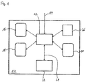
- Fig. 1 shows a configuration software 10 for creating configuration data and a PLC program for at least one control and / or protection device comprising a programmable logic controller for monitoring and / or controlling at least one drive component for at least one switching device for medium or high voltage technology in a function-oriented schematic representation ,
- the software 10 comprises a configurator program 12 with an interface 14, via which a user can input or select basic data that describe at least one switching device to be configured.
- the interface 14 comprises a graphical user interface of the configurator program 12 for the user interaction.
- the software 10 further comprises an HMI library 16, a function block database 18 and a communication database 20, each of which is connected to the configurator program 12.
- a PLC programming software 22 is integrated into the configuration software 10, which is formed by a PLC programming program and is connected to the configurator program 12 via an interface 24 for data exchange.
- the software 10 includes an import / export module 26 which is connected to the configurator program 12 and with which data from the configurator program 12 can be exported and imported into the configurator program 12.
- Fig. 2 shows a flowchart of a method for creating configuration data and a PLC program using the in Fig. 1 configuration software 10 shown.
- a project is created by user input 30.
- One or more switchgear can be assigned to the project during the process.
- the user also enters basic data relating to an entire switchgear assembly, including all switchgear panels and switchgear of the switchgear assembly, such as a primary voltage of the switchgear assembly or the type of insulation of the switchgear assembly.
- step 32 one or more switch panels for the switchgear, each with one or more switching devices, are defined by a further user input 30.
- basic data is first entered or selected that describes the control panel as a whole, such as the property of the control panel as an infeed panel, outgoing panel or coupling panel.
- one or more switching devices are selected by a user input 30, which are predefined in the HMI library 16 and which are preferably made available to the user in dependence on the basic data already entered in such a way that only functionally realizable switching fields can be specified.
- the HMI library 16 comprises information about permissible switchgear, switchgear and switchgear configurations.
- the respective switching device with the basic data predefined for this switching device in the HMI library 16 is automatically added to the configuration data.
- the predefined basic data include e.g. Information regarding auxiliary switches, auxiliary contacts, switch-on triggers, switch-off triggers and motor drives of the respective switchgear.
- step 34 program data for the PLC program to be created are automatically generated depending on the entered or selected basic data.
- Function blocks for the PLC program are automatically selected from the function block database 18 and added to the program data which are assigned to the respectively specified switching devices.
- inputs and outputs are generated automatically and the inputs, outputs and function blocks are automatically linked to one another by connections, so that the program data lead to a PLC program which contains the control and / or monitoring functions necessary for the respective switch panel and to be carried out by the PLC implemented.
- configuration data for the communication of the control and / or protective device with external devices are generated in step 36.
- the user selects corresponding ones by means of a user input 38 Data from the communication database 20, which are added to the configuration data.
- Steps 28 to 38 described above can be carried out by the configurator program without an interaction with the PLC programming software being necessary.
- the user inputs 30, 38 described above are carried out using the graphical user interface of the configurator program.
- step 40 the configuration data generated, including the program data for the PLC program and the configuration data for device communication, are ported from the configurator program into the PLC programming software upon user input in the configurator program.
- the ported program data is then supplemented in step 42 using a user input 44 using the PLC programming software.
- This addition can serve to implement higher-level control and monitoring rules.
- the control processes to be carried out by the programmable logic controller can be made dependent in the program data on information that is sent from external devices to the control and / or protective device.
- the user can use the user input 44 to select signal designations which were previously generated as part of the configuration data for the device communication and which designate information signals to be exchanged with the external devices.
- inputs and outputs for the external information are generated in the program data, which can be linked by the user through the user input 44 with logical operators in order to implement the desired dependencies.
- step 42 also takes place the generation of the PLC program from the supplemented program data, in particular by compiling.
- User input 44 can be done using a graphical user interface of the PLC programming software.
- the PLC programming software can notify the configurator program when the program data has been changed, so that the configurator program always knows whether the program data used by the configurator program is still current.
- step 46 the supplemented program data and / or the compiled PLC program are ported back into the configurator program.
- a corresponding user input in the graphical user interface of the configurator program can be used to copy one or more switch panels and / or one or more switchgear including the associated configuration data and / or an already compiled PLC program for the programmable logic controller of the item to be copied Panel.
- a switch panel or a switchgear can also be copied before the data is ported into the PLC programming software, in which case the basic data assigned to the respective switch panel and / or the respective switchgear are copied.
- step 50 the finished compiled PLC program is output by the configurator program.
- the PLC program can be loaded directly into the programmable logic controller.
- the PLC program can also be saved on a data carrier that can be used in the programmable logic controller.
- Fig. 3 shows the configuration software 10 of Fig. 1 in a memory-oriented schematic representation.
- the configuration software 10 comprises a memory area 52, in which the HMI library 16, the function block database 18, the communication database 20 and additionally a hardware library 54 are contained.
- the storage area 52 comprises a project storage area 56, in which configuration data relating to a specific project are stored.
- the data stored in the storage area 52 include a storage area 58 for a project tree structure in which the hierarchical project structure with the associated switchgear, switchgear panels and switchgear is stored.
- a further memory area 60 contains the basic data entered by the user and / or selected using the HMI library 16, which describe the switchgear, switchgear panels and switchgear.
- the program data generated from the basic data using the function block database 18 are stored in a further memory area 62.
- the configuration data selected by a user using the communication database 20 for the communication of the control and / or protective devices assigned to the various switch panels with external devices are stored in the memory area 64.
- program modules of the software 10 include a program module 66 for communicating the software 10 with the programmable logic controller or a data carrier for programming the programmable logic controller
- Program module 68 for creating documentation for the project, in particular with one or more PDF files
- Program module 26 for importing and / or exporting data in a structured data format such as an XML format
- program module 70 for backing up the data of the Project, for example as a ZIP file
- program module 72 for service functions.
Landscapes
- Engineering & Computer Science (AREA)
- Software Systems (AREA)
- General Engineering & Computer Science (AREA)
- Physics & Mathematics (AREA)
- General Physics & Mathematics (AREA)
- Theoretical Computer Science (AREA)
- Automation & Control Theory (AREA)
- Programmable Controllers (AREA)
Claims (16)
- Logiciel de configuration (10), adapté à mettre en œuvre le procédé selon la revendication 12, pour créer des données de configuration et un programme d'API pour au moins un appareil de commande et/ou de protection comprenant un automate programmable industriel pour surveiller et/ou commander au moins un composant d'entraînement pour au moins un appareil de commutation pour la technique moyenne ou haute tension,
un logiciel de programmation d'API (22) pour programmer un automate programmable industriel étant intégré dans le logiciel de configuration et le logiciel de configuration (10) comprenant des instructions pour échanger des données dans un format de données structuré avec le logiciel de programmation d'API (22). - Logiciel selon la revendication 1,
caractérisé en ce
que le logiciel de configuration (10) comprend des instructions pour mettre en œuvre un procédé de configuration qui comprend les étapes suivantes :- réception d'une entrée utilisateur (30) pour entrer ou sélectionner des données de base qui décrivent au moins un appareil de commutation à configurer,- génération de données de programme pour le programme d'API en fonction des données de base entrées ou sélectionnées et- création d'un programme d'API pour ledit au moins un appareil de commande et/ou de protection dans le logiciel de programmation d'API (22) en utilisant les données de programme. - Logiciel selon au moins l'une des revendications précédentes,
caractérisé en ce
qu'il est prévu une bibliothèque (16) dans laquelle sont contenus différents appareils de commutation prédéfinis et des données de base prédéfinies associées aux appareils de commutation prédéfinis, qui décrivent l'appareil de commutation respectif, et que, lors de l'exécution du logiciel de configuration (10) pour entrer ou sélectionner des données de base, de préférence au moins un appareil de commutation prédéfini peut être sélectionné dans la bibliothèque (16) par un utilisateur et les données de base prédéfinies contenues dans la bibliothèque (16) et associées à l'appareil de commutation sélectionné peuvent être utilisées pour la suite de la configuration. - Logiciel selon la revendication 3,
caractérisé en ce
que le logiciel de configuration (10) contient des instructions pour représenter graphiquement les appareils de commutation prédéfinis contenus dans la bibliothèque (16) sur une interface utilisateur graphique de telle sorte que ceux-ci puissent être sélectionnés par un utilisateur à l'aide de la représentation graphique respective, des schémas de circuit équivalents graphiques des appareils de commutation contenus de préférence dans la bibliothèque (16) étant affichés pour représenter graphiquement les appareils de commutation. - Logiciel selon au moins l'une des revendications précédentes,
caractérisé en ce
que, lors de l'exécution du logiciel de configuration (10), des données de base peuvent être entrées ou sélectionnées par un utilisateur, lesquelles décrivent un tableau de distribution avec un ou plusieurs appareils de commutation ou une installation de distribution comprenant plusieurs tableaux de distribution avec chaque fois un ou plusieurs appareils de commutation. - Logiciel selon au moins l'une des revendications précédentes,
caractérisé en ce
que, lors de l'exécution du logiciel de configuration (10) pour entrer ou sélectionner des données de base qui décrivent au moins un appareil de commutation, un ou plusieurs appareils de commutation, des tableaux de distribution et/ou des installations de distribution pour lesquels des données de base ont déjà été entrées ou sélectionnées peuvent être sélectionnés individuellement ou par groupes par un utilisateur et peuvent être copiés, y compris les données de base associées. - Logiciel selon au moins l'une des revendications précédentes,
caractérisé en ce
qu'il est prévu une base de données de blocs fonctionnels (18) dans laquelle sont contenus différents blocs fonctionnels prédéfinis pour le programme d'API permettant la mise en œuvre de fonctions de commande, de fonctions de signalisation et/ou de fonctions de verrouillage pour différents appareils de commutation. - Logiciel selon au moins l'une des revendications précédentes,
caractérisé en ce
qu'il est prévu une base de données de communication (20) dans laquelle sont stockées des données avec lesquelles l'appareil de commande et/ou de protection peut être configuré pour communiquer avec un ou plusieurs appareils externes disposés en dehors de l'appareil de commande et/ou de protection, les données comprenant de préférence des informations sur des protocoles de communication, sur des informations à échanger avec les appareils externes et sur les types d'adresses pour la communication avec les appareils externes. - Logiciel selon au moins l'une des revendications précédentes,
caractérisé en ce
que, lors de l'exécution du logiciel de configuration (10), des données qui contiennent des informations sur des informations à échanger avec des appareils externes peuvent être chargées dans le logiciel de programmation d'API (22), des combinaisons des informations à échanger avec des opérateurs logiques pouvant être ajoutées aux données de programme existantes pour le programme d'API par un utilisateur en utilisant le logiciel de programmation d'API (22). - Logiciel selon au moins l'une des revendications précédentes,
caractérisé en ce
que, lors de l'exécution du logiciel de configuration (10), des données de base, des données de configuration ou des données qui en dérivent déjà entrées ou sélectionnées peuvent être exportées, documentées et/ou sauvegardées sous une forme standardisée. - Logiciel selon au moins l'une des revendications précédentes,
caractérisé en ce
que des données de base ou des données de configuration à entrer ou à sélectionner lors de l'exécution du logiciel de configuration (10) peuvent être importées sous une forme standardisée. - Procédé pour créer des données de configuration et un programme d'API pour au moins un appareil de commande et/ou de protection comprenant un automate programmable industriel pour surveiller et/ou commander au moins un composant d'entraînement pour au moins un appareil de commutation pour la technique moyenne ou haute tension, dans lequel
on utilise un logiciel de configuration (10) dans lequel est intégré un logiciel de programmation d'API (22) pour programmer un automate programmable industriel,
le logiciel de configuration (10) comprenant un programme configurateur (12) qui commande le logiciel de programmation d'API (22) et/ou qui reçoit des données du logiciel de programmation d'API (22) et qui exécute ainsi automatiquement au moins l'une des étapes suivantes :- démarrage et/ou arrêt du logiciel de programmation d'API (22) et/ou d'une interface utilisateur du logiciel de programmation d'API (22),- transmission de données de programme pour le programme d'API par le programme configurateur (12) au logiciel de programmation d'API,- création d'un programme d'API pour ledit au moins un appareil de commande et/ou de protection dans le logiciel de programmation d'API (22) en utilisant des données de programme pour le programme d'API transmis par le programme configurateur (12) au logiciel de programmation d'API (22) et- réception d'un programme d'API transmis par le logiciel de programmation d'API (22) pour ledit au moins un appareil de commande et/ou de protection et/ou de données de programme pour le programme d'API transmises par le logiciel de programmation d'API (22). - Procédé selon la revendication 12,
caractérisé en ce
que, pour entrer ou sélectionner des données de base qui décrivent un appareil de commutation à configurer, un appareil de commutation prédéfini est sélectionné dans une bibliothèque (16) dans laquelle sont contenus différents appareils de commutation prédéfinis et des données de base prédéfinies associées aux appareils de commutation prédéfinis, qui décrivent l'appareil de commutation respectif, les données de base prédéfinies contenues dans la bibliothèque (16) et associées à l'appareil de commutation sélectionné étant utilisées pour la suite de la configuration. - Procédé selon l'une des revendications 12 ou 13,
caractérisé en ce
que, pour créer des données de programme pour le programme d'API, un ou plusieurs blocs fonctionnels sont sélectionnés à partir d'une base de données de blocs fonctionnels (18) dans laquelle sont contenus différents blocs fonctionnels prédéfinis pour le programme d'API permettant de mettre en œuvre des fonctions de commande, des fonctions de signalisation et/ou des fonctions de verrouillage pour différents appareils de commutation. - Procédé selon l'une des revendications 12, 13 ou 14,
caractérisé en ce
que des informations sur des informations à échanger avec des appareils externes sont chargées dans le logiciel de programmation d'API (22) et des combinaisons des informations à échanger avec des opérateurs logiques sont ajoutées aux données de programme existantes pour le programme d'API par un utilisateur en utilisant le logiciel de programmation d'API (22). - Procédé selon l'une des revendications 12 à 15,
caractérisé en ce que- une entrée utilisateur (30) pour entrer ou sélectionner des données de base qui décrivent au moins un appareil de commutation à configurer est reçue,- des données de programme pour le programme d'API sont générées en fonction des données de base entrées ou sélectionnées,- un programme d'API pour l'appareil de commande et/ou de protection est créé dans le logiciel de programmation d'API (22) en utilisant les données de programme.
Applications Claiming Priority (1)
| Application Number | Priority Date | Filing Date | Title |
|---|---|---|---|
| DE102013209676.3A DE102013209676A1 (de) | 2013-05-24 | 2013-05-24 | Konfigurationssoftware und Verfahren zum Erstellen von Konfigurationsdaten und eines PLC-Programms für ein eine speicherprogrammierbare Steuerung umfassendes Steuer- und/oder Schutzgerät für die Mittel- oder Hochspannungstechnik |
Publications (3)
| Publication Number | Publication Date |
|---|---|
| EP2806319A2 EP2806319A2 (fr) | 2014-11-26 |
| EP2806319A3 EP2806319A3 (fr) | 2014-12-10 |
| EP2806319B1 true EP2806319B1 (fr) | 2020-01-22 |
Family
ID=50943252
Family Applications (1)
| Application Number | Title | Priority Date | Filing Date |
|---|---|---|---|
| EP14305777.6A Active EP2806319B1 (fr) | 2013-05-24 | 2014-05-26 | Logiciel de configuration et procédé d'élaboration de données de configuration et d'un programme PLC pour un appareil de commande et/ou de protection comportant une commande de stockage programmable pour la technologie de moyenne ou haute tension |
Country Status (2)
| Country | Link |
|---|---|
| EP (1) | EP2806319B1 (fr) |
| DE (1) | DE102013209676A1 (fr) |
Families Citing this family (20)
| Publication number | Priority date | Publication date | Assignee | Title |
|---|---|---|---|---|
| US11144630B2 (en) | 2011-12-30 | 2021-10-12 | Bedrock Automation Platforms Inc. | Image capture devices for a secure industrial control system |
| US9437967B2 (en) | 2011-12-30 | 2016-09-06 | Bedrock Automation Platforms, Inc. | Electromagnetic connector for an industrial control system |
| US9600434B1 (en) | 2011-12-30 | 2017-03-21 | Bedrock Automation Platforms, Inc. | Switch fabric having a serial communications interface and a parallel communications interface |
| US9191203B2 (en) | 2013-08-06 | 2015-11-17 | Bedrock Automation Platforms Inc. | Secure industrial control system |
| US11314854B2 (en) | 2011-12-30 | 2022-04-26 | Bedrock Automation Platforms Inc. | Image capture devices for a secure industrial control system |
| US10834820B2 (en) | 2013-08-06 | 2020-11-10 | Bedrock Automation Platforms Inc. | Industrial control system cable |
| US8971072B2 (en) | 2011-12-30 | 2015-03-03 | Bedrock Automation Platforms Inc. | Electromagnetic connector for an industrial control system |
| US10834094B2 (en) | 2013-08-06 | 2020-11-10 | Bedrock Automation Platforms Inc. | Operator action authentication in an industrial control system |
| US11967839B2 (en) | 2011-12-30 | 2024-04-23 | Analog Devices, Inc. | Electromagnetic connector for an industrial control system |
| US8862802B2 (en) | 2011-12-30 | 2014-10-14 | Bedrock Automation Platforms Inc. | Switch fabric having a serial communications interface and a parallel communications interface |
| US9727511B2 (en) | 2011-12-30 | 2017-08-08 | Bedrock Automation Platforms Inc. | Input/output module with multi-channel switching capability |
| US9467297B2 (en) | 2013-08-06 | 2016-10-11 | Bedrock Automation Platforms Inc. | Industrial control system redundant communications/control modules authentication |
| US8868813B2 (en) | 2011-12-30 | 2014-10-21 | Bedrock Automation Platforms Inc. | Communications control system with a serial communications interface and a parallel communications interface |
| US10613567B2 (en) | 2013-08-06 | 2020-04-07 | Bedrock Automation Platforms Inc. | Secure power supply for an industrial control system |
| JP7029220B2 (ja) * | 2015-02-09 | 2022-03-03 | ベドロック・オートメーション・プラットフォームズ・インコーポレーテッド | 多チャネル切り替え能力を有する入力/出力モジュール |
| CN106980304B (zh) * | 2016-01-15 | 2019-05-31 | 施耐德电器工业公司 | 用于可编程控制器的编程装置以及编程方法 |
| CN106940553B (zh) * | 2017-02-09 | 2020-06-16 | 北京东土科技股份有限公司 | 基于工业互联网操作系统的工业流程控制管理方法及装置 |
| CN109814480B (zh) * | 2019-01-18 | 2021-10-08 | 广州宁基智能系统有限公司 | Plc与线控程序之间的可视化交互方法及系统 |
| CN111562492A (zh) * | 2020-05-08 | 2020-08-21 | 广东电网有限责任公司 | 一种刀闸电机运行状态远程监测系统 |
| CN112596485B (zh) * | 2020-12-22 | 2022-05-27 | 浙江中控技术股份有限公司 | 一种工业控制系统中组态数据封装及重用的方法和装置 |
Family Cites Families (8)
| Publication number | Priority date | Publication date | Assignee | Title |
|---|---|---|---|---|
| DE10140763A1 (de) * | 2001-08-20 | 2003-03-06 | Siemens Ag | Verfahren und Anordnung zur Konfiguration von Baugruppen in einer Datenverarbeitungsanlage |
| US6973508B2 (en) * | 2002-02-12 | 2005-12-06 | Fisher-Rosemount Systems, Inc. | Highly versatile process control system controller |
| WO2007149688A2 (fr) * | 2006-05-30 | 2007-12-27 | Schneider Automation Inc. | Configuration de paramètre fictif virtuel distant pour des modules d'entrée/sortie distribuées |
| US20070291437A1 (en) * | 2006-06-16 | 2007-12-20 | Gefran S.P.A. | Power Regulator Supplied to Electric Charges of Industrial Processes |
| DE102008035654A1 (de) * | 2007-07-31 | 2009-02-05 | Fraunhofer-Gesellschaft zur Förderung der angewandten Forschung e.V. | Verfahren zur Anpassung einer Steuerungslogik eines Systems |
| EP2063331A1 (fr) * | 2007-11-21 | 2009-05-27 | Pepperl + Fuchs Gmbh | Capteur pour la technique d'automatisation et procédé de configuration d'un capteur |
| DE102010010014B3 (de) * | 2010-03-03 | 2011-04-21 | Sick Ag | Sicherheitsvorrichtung mit einer konfigurierbaren Sicherheitssteuerung |
| DE102010026494A1 (de) * | 2010-07-07 | 2012-01-12 | Abb Ag | Verfahren zur Konfigurierung einer Steuerungseinrichtung |
-
2013
- 2013-05-24 DE DE102013209676.3A patent/DE102013209676A1/de not_active Withdrawn
-
2014
- 2014-05-26 EP EP14305777.6A patent/EP2806319B1/fr active Active
Non-Patent Citations (1)
| Title |
|---|
| None * |
Also Published As
| Publication number | Publication date |
|---|---|
| EP2806319A2 (fr) | 2014-11-26 |
| DE102013209676A1 (de) | 2014-11-27 |
| EP2806319A3 (fr) | 2014-12-10 |
Similar Documents
| Publication | Publication Date | Title |
|---|---|---|
| EP2806319B1 (fr) | Logiciel de configuration et procédé d'élaboration de données de configuration et d'un programme PLC pour un appareil de commande et/ou de protection comportant une commande de stockage programmable pour la technologie de moyenne ou haute tension | |
| EP1096348B1 (fr) | Intégration d'un appareil de commande sur site dans un système de commande d'une installation | |
| EP2012201B1 (fr) | Procédé destiné à la programmation d'une commande de sécurité | |
| EP2098926B1 (fr) | Procédé et dispositif adaptés à la programmation et/ou la configuration d'un contrôleur de sécurité | |
| EP2356527B1 (fr) | Commande de sécurité et procédé pour commander une installation automatisée comprenant une pluralité de composants matériels | |
| EP1341636A1 (fr) | Procede pour relier plusieurs postes de soudage et poste de soudage correspondant | |
| EP2098925A1 (fr) | Procédé et dispositif adaptés à la programmation et/ou la configuration d'un contrôleur de sécurité | |
| EP2353051A1 (fr) | Procédé et dispositif pour établir un programme utilisateur pour une commande de sécurité | |
| DE102011107318A1 (de) | Verfahren zur Konfigurierung eines Kommunikationsschnittstellenmoduls in einem Steuerungs- oder Automatisierungssystem | |
| EP2098924A1 (fr) | Procédé et dispositif adaptés à la programmation et/ou la configuration d'un contrôleur de sécurité | |
| EP2098928A1 (fr) | Procédé et dispositif adaptés à la programmation et/ou la configuration d'un contrôleur de sécurité | |
| EP2422248B1 (fr) | Système et procédé de répartition de données de projets d'un controlleur de sécurité d'une installation automatisée aux composants de commande | |
| WO2005022286A2 (fr) | Procede de projection graphique de la commande d'une installation technique a projection integree d'appareils d'exploitation, y compris un systeme de projection et un progiciel informatique | |
| EP2525453B1 (fr) | Egalisation de paramètre d'un module d'introduction d'une installation de commutation à basse tension électrique | |
| EP2359571B1 (fr) | Dispositif présentant un appareil de centre de commande et une station d'installations en liaison avec celui-ci, et procédé permettant son fonctionnement | |
| EP2883294B1 (fr) | Procédé de commande assistée par ordinateur d'un réseau de distribution d'énergie électrique composé d'une pluralité de noeuds | |
| EP3082001A1 (fr) | Procédé d'extension d'un dispositif d'automatisation avec un virtuel appareil d'automatisation et dispositif d'automatisation | |
| EP1929382B1 (fr) | Appareil de parametrage et procede de parametrage d'appareils electriques | |
| EP1431898A2 (fr) | Système d'automatisation et méthode pour la mise en oeuvre d'un tel système | |
| EP3396480B1 (fr) | Procédé de programmation d'un dispositif de sécurité | |
| WO2008067943A1 (fr) | Installation de commutation à isolation de gaz | |
| EP4086754A1 (fr) | Procédé de configuration assistée par ordinateur d'un équipement terminal, équipement terminal et procédé de fonctionnement pour l'équipement terminal | |
| EP1196829A1 (fr) | Module de commande d'un mecanisme d'entrainement | |
| DE102014214864A1 (de) | Parametrierung, Projektierung und/oder Programmierung eines Schaltgerätes | |
| EP4141459A1 (fr) | Instrument d'exécution autonome de séquences d'essai selon la norme jtag |
Legal Events
| Date | Code | Title | Description |
|---|---|---|---|
| PUAL | Search report despatched |
Free format text: ORIGINAL CODE: 0009013 |
|
| PUAI | Public reference made under article 153(3) epc to a published international application that has entered the european phase |
Free format text: ORIGINAL CODE: 0009012 |
|
| 17P | Request for examination filed |
Effective date: 20140526 |
|
| AK | Designated contracting states |
Kind code of ref document: A2 Designated state(s): AL AT BE BG CH CY CZ DE DK EE ES FI FR GB GR HR HU IE IS IT LI LT LU LV MC MK MT NL NO PL PT RO RS SE SI SK SM TR |
|
| AX | Request for extension of the european patent |
Extension state: BA ME |
|
| AK | Designated contracting states |
Kind code of ref document: A3 Designated state(s): AL AT BE BG CH CY CZ DE DK EE ES FI FR GB GR HR HU IE IS IT LI LT LU LV MC MK MT NL NO PL PT RO RS SE SI SK SM TR |
|
| AX | Request for extension of the european patent |
Extension state: BA ME |
|
| RIC1 | Information provided on ipc code assigned before grant |
Ipc: G06F 9/44 20060101ALI20141031BHEP Ipc: G05B 19/05 20060101AFI20141031BHEP |
|
| R17P | Request for examination filed (corrected) |
Effective date: 20150602 |
|
| RBV | Designated contracting states (corrected) |
Designated state(s): AL AT BE BG CH CY CZ DE DK EE ES FI FR GB GR HR HU IE IS IT LI LT LU LV MC MK MT NL NO PL PT RO RS SE SI SK SM TR |
|
| STAA | Information on the status of an ep patent application or granted ep patent |
Free format text: STATUS: EXAMINATION IS IN PROGRESS |
|
| 17Q | First examination report despatched |
Effective date: 20190222 |
|
| RIC1 | Information provided on ipc code assigned before grant |
Ipc: G05B 19/05 20060101AFI20190529BHEP Ipc: G06F 8/34 20180101ALI20190529BHEP Ipc: G06F 9/44 20180101ALI20190529BHEP |
|
| GRAP | Despatch of communication of intention to grant a patent |
Free format text: ORIGINAL CODE: EPIDOSNIGR1 |
|
| STAA | Information on the status of an ep patent application or granted ep patent |
Free format text: STATUS: GRANT OF PATENT IS INTENDED |
|
| INTG | Intention to grant announced |
Effective date: 20190716 |
|
| RIN1 | Information on inventor provided before grant (corrected) |
Inventor name: ZELLER, FRANZ Inventor name: BROWN, PAUL Inventor name: MILLAUD, ERIC Inventor name: BOGIE, WOLFGANG |
|
| GRAS | Grant fee paid |
Free format text: ORIGINAL CODE: EPIDOSNIGR3 |
|
| GRAA | (expected) grant |
Free format text: ORIGINAL CODE: 0009210 |
|
| STAA | Information on the status of an ep patent application or granted ep patent |
Free format text: STATUS: THE PATENT HAS BEEN GRANTED |
|
| AK | Designated contracting states |
Kind code of ref document: B1 Designated state(s): AL AT BE BG CH CY CZ DE DK EE ES FI FR GB GR HR HU IE IS IT LI LT LU LV MC MK MT NL NO PL PT RO RS SE SI SK SM TR |
|
| REG | Reference to a national code |
Ref country code: GB Ref legal event code: FG4D Free format text: NOT ENGLISH |
|
| REG | Reference to a national code |
Ref country code: CH Ref legal event code: EP |
|
| REG | Reference to a national code |
Ref country code: DE Ref legal event code: R096 Ref document number: 502014013524 Country of ref document: DE |
|
| REG | Reference to a national code |
Ref country code: AT Ref legal event code: REF Ref document number: 1227313 Country of ref document: AT Kind code of ref document: T Effective date: 20200215 |
|
| REG | Reference to a national code |
Ref country code: IE Ref legal event code: FG4D Free format text: LANGUAGE OF EP DOCUMENT: GERMAN |
|
| REG | Reference to a national code |
Ref country code: NL Ref legal event code: MP Effective date: 20200122 |
|
| REG | Reference to a national code |
Ref country code: LT Ref legal event code: MG4D |
|
| PG25 | Lapsed in a contracting state [announced via postgrant information from national office to epo] |
Ref country code: NO Free format text: LAPSE BECAUSE OF FAILURE TO SUBMIT A TRANSLATION OF THE DESCRIPTION OR TO PAY THE FEE WITHIN THE PRESCRIBED TIME-LIMIT Effective date: 20200422 Ref country code: FI Free format text: LAPSE BECAUSE OF FAILURE TO SUBMIT A TRANSLATION OF THE DESCRIPTION OR TO PAY THE FEE WITHIN THE PRESCRIBED TIME-LIMIT Effective date: 20200122 Ref country code: RS Free format text: LAPSE BECAUSE OF FAILURE TO SUBMIT A TRANSLATION OF THE DESCRIPTION OR TO PAY THE FEE WITHIN THE PRESCRIBED TIME-LIMIT Effective date: 20200122 Ref country code: NL Free format text: LAPSE BECAUSE OF FAILURE TO SUBMIT A TRANSLATION OF THE DESCRIPTION OR TO PAY THE FEE WITHIN THE PRESCRIBED TIME-LIMIT Effective date: 20200122 Ref country code: PT Free format text: LAPSE BECAUSE OF FAILURE TO SUBMIT A TRANSLATION OF THE DESCRIPTION OR TO PAY THE FEE WITHIN THE PRESCRIBED TIME-LIMIT Effective date: 20200614 |
|
| PG25 | Lapsed in a contracting state [announced via postgrant information from national office to epo] |
Ref country code: BG Free format text: LAPSE BECAUSE OF FAILURE TO SUBMIT A TRANSLATION OF THE DESCRIPTION OR TO PAY THE FEE WITHIN THE PRESCRIBED TIME-LIMIT Effective date: 20200422 Ref country code: GR Free format text: LAPSE BECAUSE OF FAILURE TO SUBMIT A TRANSLATION OF THE DESCRIPTION OR TO PAY THE FEE WITHIN THE PRESCRIBED TIME-LIMIT Effective date: 20200423 Ref country code: IS Free format text: LAPSE BECAUSE OF FAILURE TO SUBMIT A TRANSLATION OF THE DESCRIPTION OR TO PAY THE FEE WITHIN THE PRESCRIBED TIME-LIMIT Effective date: 20200522 Ref country code: LV Free format text: LAPSE BECAUSE OF FAILURE TO SUBMIT A TRANSLATION OF THE DESCRIPTION OR TO PAY THE FEE WITHIN THE PRESCRIBED TIME-LIMIT Effective date: 20200122 Ref country code: SE Free format text: LAPSE BECAUSE OF FAILURE TO SUBMIT A TRANSLATION OF THE DESCRIPTION OR TO PAY THE FEE WITHIN THE PRESCRIBED TIME-LIMIT Effective date: 20200122 Ref country code: HR Free format text: LAPSE BECAUSE OF FAILURE TO SUBMIT A TRANSLATION OF THE DESCRIPTION OR TO PAY THE FEE WITHIN THE PRESCRIBED TIME-LIMIT Effective date: 20200122 |
|
| REG | Reference to a national code |
Ref country code: DE Ref legal event code: R097 Ref document number: 502014013524 Country of ref document: DE |
|
| PG25 | Lapsed in a contracting state [announced via postgrant information from national office to epo] |
Ref country code: RO Free format text: LAPSE BECAUSE OF FAILURE TO SUBMIT A TRANSLATION OF THE DESCRIPTION OR TO PAY THE FEE WITHIN THE PRESCRIBED TIME-LIMIT Effective date: 20200122 Ref country code: SM Free format text: LAPSE BECAUSE OF FAILURE TO SUBMIT A TRANSLATION OF THE DESCRIPTION OR TO PAY THE FEE WITHIN THE PRESCRIBED TIME-LIMIT Effective date: 20200122 Ref country code: EE Free format text: LAPSE BECAUSE OF FAILURE TO SUBMIT A TRANSLATION OF THE DESCRIPTION OR TO PAY THE FEE WITHIN THE PRESCRIBED TIME-LIMIT Effective date: 20200122 Ref country code: DK Free format text: LAPSE BECAUSE OF FAILURE TO SUBMIT A TRANSLATION OF THE DESCRIPTION OR TO PAY THE FEE WITHIN THE PRESCRIBED TIME-LIMIT Effective date: 20200122 Ref country code: LT Free format text: LAPSE BECAUSE OF FAILURE TO SUBMIT A TRANSLATION OF THE DESCRIPTION OR TO PAY THE FEE WITHIN THE PRESCRIBED TIME-LIMIT Effective date: 20200122 Ref country code: ES Free format text: LAPSE BECAUSE OF FAILURE TO SUBMIT A TRANSLATION OF THE DESCRIPTION OR TO PAY THE FEE WITHIN THE PRESCRIBED TIME-LIMIT Effective date: 20200122 Ref country code: CZ Free format text: LAPSE BECAUSE OF FAILURE TO SUBMIT A TRANSLATION OF THE DESCRIPTION OR TO PAY THE FEE WITHIN THE PRESCRIBED TIME-LIMIT Effective date: 20200122 Ref country code: SK Free format text: LAPSE BECAUSE OF FAILURE TO SUBMIT A TRANSLATION OF THE DESCRIPTION OR TO PAY THE FEE WITHIN THE PRESCRIBED TIME-LIMIT Effective date: 20200122 |
|
| PLBE | No opposition filed within time limit |
Free format text: ORIGINAL CODE: 0009261 |
|
| STAA | Information on the status of an ep patent application or granted ep patent |
Free format text: STATUS: NO OPPOSITION FILED WITHIN TIME LIMIT |
|
| 26N | No opposition filed |
Effective date: 20201023 |
|
| PG25 | Lapsed in a contracting state [announced via postgrant information from national office to epo] |
Ref country code: MC Free format text: LAPSE BECAUSE OF FAILURE TO SUBMIT A TRANSLATION OF THE DESCRIPTION OR TO PAY THE FEE WITHIN THE PRESCRIBED TIME-LIMIT Effective date: 20200122 Ref country code: CH Free format text: LAPSE BECAUSE OF NON-PAYMENT OF DUE FEES Effective date: 20200531 Ref country code: LI Free format text: LAPSE BECAUSE OF NON-PAYMENT OF DUE FEES Effective date: 20200531 Ref country code: IT Free format text: LAPSE BECAUSE OF FAILURE TO SUBMIT A TRANSLATION OF THE DESCRIPTION OR TO PAY THE FEE WITHIN THE PRESCRIBED TIME-LIMIT Effective date: 20200122 |
|
| PG25 | Lapsed in a contracting state [announced via postgrant information from national office to epo] |
Ref country code: SI Free format text: LAPSE BECAUSE OF FAILURE TO SUBMIT A TRANSLATION OF THE DESCRIPTION OR TO PAY THE FEE WITHIN THE PRESCRIBED TIME-LIMIT Effective date: 20200122 Ref country code: PL Free format text: LAPSE BECAUSE OF FAILURE TO SUBMIT A TRANSLATION OF THE DESCRIPTION OR TO PAY THE FEE WITHIN THE PRESCRIBED TIME-LIMIT Effective date: 20200122 |
|
| REG | Reference to a national code |
Ref country code: BE Ref legal event code: MM Effective date: 20200531 |
|
| GBPC | Gb: european patent ceased through non-payment of renewal fee |
Effective date: 20200526 |
|
| PG25 | Lapsed in a contracting state [announced via postgrant information from national office to epo] |
Ref country code: LU Free format text: LAPSE BECAUSE OF NON-PAYMENT OF DUE FEES Effective date: 20200526 |
|
| PG25 | Lapsed in a contracting state [announced via postgrant information from national office to epo] |
Ref country code: GB Free format text: LAPSE BECAUSE OF NON-PAYMENT OF DUE FEES Effective date: 20200526 Ref country code: IE Free format text: LAPSE BECAUSE OF NON-PAYMENT OF DUE FEES Effective date: 20200526 |
|
| PG25 | Lapsed in a contracting state [announced via postgrant information from national office to epo] |
Ref country code: BE Free format text: LAPSE BECAUSE OF NON-PAYMENT OF DUE FEES Effective date: 20200531 |
|
| REG | Reference to a national code |
Ref country code: AT Ref legal event code: MM01 Ref document number: 1227313 Country of ref document: AT Kind code of ref document: T Effective date: 20200526 |
|
| PG25 | Lapsed in a contracting state [announced via postgrant information from national office to epo] |
Ref country code: AT Free format text: LAPSE BECAUSE OF NON-PAYMENT OF DUE FEES Effective date: 20200526 |
|
| PG25 | Lapsed in a contracting state [announced via postgrant information from national office to epo] |
Ref country code: TR Free format text: LAPSE BECAUSE OF FAILURE TO SUBMIT A TRANSLATION OF THE DESCRIPTION OR TO PAY THE FEE WITHIN THE PRESCRIBED TIME-LIMIT Effective date: 20200122 Ref country code: MT Free format text: LAPSE BECAUSE OF FAILURE TO SUBMIT A TRANSLATION OF THE DESCRIPTION OR TO PAY THE FEE WITHIN THE PRESCRIBED TIME-LIMIT Effective date: 20200122 Ref country code: CY Free format text: LAPSE BECAUSE OF FAILURE TO SUBMIT A TRANSLATION OF THE DESCRIPTION OR TO PAY THE FEE WITHIN THE PRESCRIBED TIME-LIMIT Effective date: 20200122 |
|
| PG25 | Lapsed in a contracting state [announced via postgrant information from national office to epo] |
Ref country code: MK Free format text: LAPSE BECAUSE OF FAILURE TO SUBMIT A TRANSLATION OF THE DESCRIPTION OR TO PAY THE FEE WITHIN THE PRESCRIBED TIME-LIMIT Effective date: 20200122 Ref country code: AL Free format text: LAPSE BECAUSE OF FAILURE TO SUBMIT A TRANSLATION OF THE DESCRIPTION OR TO PAY THE FEE WITHIN THE PRESCRIBED TIME-LIMIT Effective date: 20200122 |
|
| REG | Reference to a national code |
Ref country code: FR Ref legal event code: PLFP Year of fee payment: 10 |
|
| PGFP | Annual fee paid to national office [announced via postgrant information from national office to epo] |
Ref country code: FR Payment date: 20230411 Year of fee payment: 10 Ref country code: DE Payment date: 20230331 Year of fee payment: 10 |