EP2806155B1 - Vorrichtung zur Bewegung eines Rotorblatts einer Windturbine, Verfahren zur Reparatur des Blattlagers damit und Windturbine damit - Google Patents
Vorrichtung zur Bewegung eines Rotorblatts einer Windturbine, Verfahren zur Reparatur des Blattlagers damit und Windturbine damit Download PDFInfo
- Publication number
- EP2806155B1 EP2806155B1 EP13738768.4A EP13738768A EP2806155B1 EP 2806155 B1 EP2806155 B1 EP 2806155B1 EP 13738768 A EP13738768 A EP 13738768A EP 2806155 B1 EP2806155 B1 EP 2806155B1
- Authority
- EP
- European Patent Office
- Prior art keywords
- blade
- wire
- wind turbine
- blades
- protrusions
- Prior art date
- Legal status (The legal status is an assumption and is not a legal conclusion. Google has not performed a legal analysis and makes no representation as to the accuracy of the status listed.)
- Not-in-force
Links
- 238000000034 method Methods 0.000 title claims description 24
- 230000008878 coupling Effects 0.000 claims description 7
- 238000010168 coupling process Methods 0.000 claims description 7
- 238000005859 coupling reaction Methods 0.000 claims description 7
- 230000002093 peripheral effect Effects 0.000 claims description 3
- 230000008439 repair process Effects 0.000 description 11
- 230000005484 gravity Effects 0.000 description 3
- 230000000694 effects Effects 0.000 description 1
- 230000005611 electricity Effects 0.000 description 1
Images


Classifications
-
- F—MECHANICAL ENGINEERING; LIGHTING; HEATING; WEAPONS; BLASTING
- F03—MACHINES OR ENGINES FOR LIQUIDS; WIND, SPRING, OR WEIGHT MOTORS; PRODUCING MECHANICAL POWER OR A REACTIVE PROPULSIVE THRUST, NOT OTHERWISE PROVIDED FOR
- F03D—WIND MOTORS
- F03D1/00—Wind motors with rotation axis substantially parallel to the air flow entering the rotor
- F03D1/06—Rotors
- F03D1/065—Rotors characterised by their construction elements
- F03D1/0658—Arrangements for fixing wind-engaging parts to a hub
-
- F—MECHANICAL ENGINEERING; LIGHTING; HEATING; WEAPONS; BLASTING
- F03—MACHINES OR ENGINES FOR LIQUIDS; WIND, SPRING, OR WEIGHT MOTORS; PRODUCING MECHANICAL POWER OR A REACTIVE PROPULSIVE THRUST, NOT OTHERWISE PROVIDED FOR
- F03D—WIND MOTORS
- F03D1/00—Wind motors with rotation axis substantially parallel to the air flow entering the rotor
- F03D1/06—Rotors
- F03D1/065—Rotors characterised by their construction elements
- F03D1/0675—Rotors characterised by their construction elements of the blades
-
- F—MECHANICAL ENGINEERING; LIGHTING; HEATING; WEAPONS; BLASTING
- F03—MACHINES OR ENGINES FOR LIQUIDS; WIND, SPRING, OR WEIGHT MOTORS; PRODUCING MECHANICAL POWER OR A REACTIVE PROPULSIVE THRUST, NOT OTHERWISE PROVIDED FOR
- F03D—WIND MOTORS
- F03D13/00—Assembly, mounting or commissioning of wind motors; Arrangements specially adapted for transporting wind motor components
- F03D13/10—Assembly of wind motors; Arrangements for erecting wind motors
-
- F—MECHANICAL ENGINEERING; LIGHTING; HEATING; WEAPONS; BLASTING
- F03—MACHINES OR ENGINES FOR LIQUIDS; WIND, SPRING, OR WEIGHT MOTORS; PRODUCING MECHANICAL POWER OR A REACTIVE PROPULSIVE THRUST, NOT OTHERWISE PROVIDED FOR
- F03D—WIND MOTORS
- F03D13/00—Assembly, mounting or commissioning of wind motors; Arrangements specially adapted for transporting wind motor components
- F03D13/40—Arrangements or methods specially adapted for transporting wind motor components
-
- F—MECHANICAL ENGINEERING; LIGHTING; HEATING; WEAPONS; BLASTING
- F03—MACHINES OR ENGINES FOR LIQUIDS; WIND, SPRING, OR WEIGHT MOTORS; PRODUCING MECHANICAL POWER OR A REACTIVE PROPULSIVE THRUST, NOT OTHERWISE PROVIDED FOR
- F03D—WIND MOTORS
- F03D7/00—Controlling wind motors
- F03D7/02—Controlling wind motors the wind motors having rotation axis substantially parallel to the air flow entering the rotor
- F03D7/022—Adjusting aerodynamic properties of the blades
- F03D7/0224—Adjusting blade pitch
-
- F—MECHANICAL ENGINEERING; LIGHTING; HEATING; WEAPONS; BLASTING
- F03—MACHINES OR ENGINES FOR LIQUIDS; WIND, SPRING, OR WEIGHT MOTORS; PRODUCING MECHANICAL POWER OR A REACTIVE PROPULSIVE THRUST, NOT OTHERWISE PROVIDED FOR
- F03D—WIND MOTORS
- F03D80/00—Details, components or accessories not provided for in groups F03D1/00 - F03D17/00
- F03D80/50—Maintenance or repair
-
- F—MECHANICAL ENGINEERING; LIGHTING; HEATING; WEAPONS; BLASTING
- F03—MACHINES OR ENGINES FOR LIQUIDS; WIND, SPRING, OR WEIGHT MOTORS; PRODUCING MECHANICAL POWER OR A REACTIVE PROPULSIVE THRUST, NOT OTHERWISE PROVIDED FOR
- F03D—WIND MOTORS
- F03D80/00—Details, components or accessories not provided for in groups F03D1/00 - F03D17/00
- F03D80/70—Bearing or lubricating arrangements
-
- F—MECHANICAL ENGINEERING; LIGHTING; HEATING; WEAPONS; BLASTING
- F05—INDEXING SCHEMES RELATING TO ENGINES OR PUMPS IN VARIOUS SUBCLASSES OF CLASSES F01-F04
- F05B—INDEXING SCHEME RELATING TO WIND, SPRING, WEIGHT, INERTIA OR LIKE MOTORS, TO MACHINES OR ENGINES FOR LIQUIDS COVERED BY SUBCLASSES F03B, F03D AND F03G
- F05B2230/00—Manufacture
- F05B2230/60—Assembly methods
- F05B2230/61—Assembly methods using auxiliary equipment for lifting or holding
-
- F—MECHANICAL ENGINEERING; LIGHTING; HEATING; WEAPONS; BLASTING
- F05—INDEXING SCHEMES RELATING TO ENGINES OR PUMPS IN VARIOUS SUBCLASSES OF CLASSES F01-F04
- F05B—INDEXING SCHEME RELATING TO WIND, SPRING, WEIGHT, INERTIA OR LIKE MOTORS, TO MACHINES OR ENGINES FOR LIQUIDS COVERED BY SUBCLASSES F03B, F03D AND F03G
- F05B2230/00—Manufacture
- F05B2230/80—Repairing, retrofitting or upgrading methods
-
- F—MECHANICAL ENGINEERING; LIGHTING; HEATING; WEAPONS; BLASTING
- F05—INDEXING SCHEMES RELATING TO ENGINES OR PUMPS IN VARIOUS SUBCLASSES OF CLASSES F01-F04
- F05B—INDEXING SCHEME RELATING TO WIND, SPRING, WEIGHT, INERTIA OR LIKE MOTORS, TO MACHINES OR ENGINES FOR LIQUIDS COVERED BY SUBCLASSES F03B, F03D AND F03G
- F05B2240/00—Components
- F05B2240/90—Mounting on supporting structures or systems
- F05B2240/91—Mounting on supporting structures or systems on a stationary structure
- F05B2240/916—Mounting on supporting structures or systems on a stationary structure with provision for hoisting onto the structure
-
- Y—GENERAL TAGGING OF NEW TECHNOLOGICAL DEVELOPMENTS; GENERAL TAGGING OF CROSS-SECTIONAL TECHNOLOGIES SPANNING OVER SEVERAL SECTIONS OF THE IPC; TECHNICAL SUBJECTS COVERED BY FORMER USPC CROSS-REFERENCE ART COLLECTIONS [XRACs] AND DIGESTS
- Y02—TECHNOLOGIES OR APPLICATIONS FOR MITIGATION OR ADAPTATION AGAINST CLIMATE CHANGE
- Y02E—REDUCTION OF GREENHOUSE GAS [GHG] EMISSIONS, RELATED TO ENERGY GENERATION, TRANSMISSION OR DISTRIBUTION
- Y02E10/00—Energy generation through renewable energy sources
- Y02E10/70—Wind energy
- Y02E10/72—Wind turbines with rotation axis in wind direction
-
- Y—GENERAL TAGGING OF NEW TECHNOLOGICAL DEVELOPMENTS; GENERAL TAGGING OF CROSS-SECTIONAL TECHNOLOGIES SPANNING OVER SEVERAL SECTIONS OF THE IPC; TECHNICAL SUBJECTS COVERED BY FORMER USPC CROSS-REFERENCE ART COLLECTIONS [XRACs] AND DIGESTS
- Y02—TECHNOLOGIES OR APPLICATIONS FOR MITIGATION OR ADAPTATION AGAINST CLIMATE CHANGE
- Y02E—REDUCTION OF GREENHOUSE GAS [GHG] EMISSIONS, RELATED TO ENERGY GENERATION, TRANSMISSION OR DISTRIBUTION
- Y02E10/00—Energy generation through renewable energy sources
- Y02E10/70—Wind energy
- Y02E10/728—Onshore wind turbines
-
- Y—GENERAL TAGGING OF NEW TECHNOLOGICAL DEVELOPMENTS; GENERAL TAGGING OF CROSS-SECTIONAL TECHNOLOGIES SPANNING OVER SEVERAL SECTIONS OF THE IPC; TECHNICAL SUBJECTS COVERED BY FORMER USPC CROSS-REFERENCE ART COLLECTIONS [XRACs] AND DIGESTS
- Y02—TECHNOLOGIES OR APPLICATIONS FOR MITIGATION OR ADAPTATION AGAINST CLIMATE CHANGE
- Y02P—CLIMATE CHANGE MITIGATION TECHNOLOGIES IN THE PRODUCTION OR PROCESSING OF GOODS
- Y02P70/00—Climate change mitigation technologies in the production process for final industrial or consumer products
- Y02P70/50—Manufacturing or production processes characterised by the final manufactured product
-
- Y—GENERAL TAGGING OF NEW TECHNOLOGICAL DEVELOPMENTS; GENERAL TAGGING OF CROSS-SECTIONAL TECHNOLOGIES SPANNING OVER SEVERAL SECTIONS OF THE IPC; TECHNICAL SUBJECTS COVERED BY FORMER USPC CROSS-REFERENCE ART COLLECTIONS [XRACs] AND DIGESTS
- Y10—TECHNICAL SUBJECTS COVERED BY FORMER USPC
- Y10T—TECHNICAL SUBJECTS COVERED BY FORMER US CLASSIFICATION
- Y10T29/00—Metal working
- Y10T29/37—Impeller making apparatus
-
- Y—GENERAL TAGGING OF NEW TECHNOLOGICAL DEVELOPMENTS; GENERAL TAGGING OF CROSS-SECTIONAL TECHNOLOGIES SPANNING OVER SEVERAL SECTIONS OF THE IPC; TECHNICAL SUBJECTS COVERED BY FORMER USPC CROSS-REFERENCE ART COLLECTIONS [XRACs] AND DIGESTS
- Y10—TECHNICAL SUBJECTS COVERED BY FORMER USPC
- Y10T—TECHNICAL SUBJECTS COVERED BY FORMER US CLASSIFICATION
- Y10T29/00—Metal working
- Y10T29/49—Method of mechanical manufacture
- Y10T29/49316—Impeller making
- Y10T29/49318—Repairing or disassembling
Definitions
- the present invention relates to a wind turbine, and more particularly, to an apparatus for moving blades of a wind turbine, a method for repairing pitch bearings using the same, and a wind turbine including the same.
- EP 2 312 152 A2 relates to a wind turbine including a tower member a yaw system, a central hub and a plurality of blade members.
- the wind turbine further includes a component manipulating system operatively coupled between at least one of the plurality of blade members and the tower member.
- the component manipulating system includes a blade member support structure including a first end pivotally connected relative to the tower member that extends to a second end operatively coupled to the one of the plurality of blade members, and a winching system operatively connected to the one of the plurality of blade members and the tower member.
- the winching system is selectively operated to shift the one of the plurality of blade members relative to the tower member in order to enable serving of the wind turbine.
- US 2007/290426 A1 concerns a device for mounting and/or dismantling a a rotor blade of a wind turbine comprising a tower head.
- Said device comprises at least one guide element that stretches between the tower head and the ground and has at least one supporting device that is essentially fixed in the air, supporting at least a partial load of the weight of the component during the transport of the latter between the ground and the wind turbine.
- US 20110/139062 A1 discloses a method and lifting arrangement for lowering and raising a single rotor blade of a wind turbine from a' six-o'clock position is provided.
- Lifting fixtures are symmetrically installed on a hub surface about the rotor blade being replaced.
- Lifting lines from coordinated ground winches pass over the lifting fixtures to support the blade and attach to a blade harness.
- the blade harness attaches over a substantial length of the rotor blade, distributing the blade weight broadly.
- a tail pick crane facilitates transfer of the rotor blade between a vertical and a horizontal position stored position.
- FIG. 1 is a perspective view of a wind turbine.
- a wind turbine 1 that generates power by wind which is a form of natural energy, includes a nacelle 3 installed on top of a tower 2, a hub 4 installed in front of the nacelle 3, and blades 5 installed at the hub 4.
- the wind turbine is generally a three-bladed design. That is, three blades 5a, 5b, and 5c are installed at the hub 4 at 120-degree intervals.
- the nacelle 3 is connected to the hub 4 by a main shaft adapted to rotate together with the hub 4, and a speed-up gear connected to the main shaft and a generator connected to the speed-up gear are installed inside the nacelle 3.
- the wind turbine 1 produces electricity using a generator as the main shaft rotates with the rotation of the blades 5, and torque of the speed-up gear connected to the main shaft is transferred to the generator inside the nacelle.
- the blades 5 of the wind turbine 1 are connected to the hub while being connected to pitch bearings in order to change their angle of attack according to the wind speed.
- the pitch of a blade can be changed in the range of 0 to 90 degrees.
- the inner rings of the pitch bearings which are worn by internal gears of the pitch bearings, should also be able to be changed in the range of 0 to 90 degrees, when the pitch of the blades 5 is changed.
- the area of contact between the internal gears of the pitch bearings and the inner rings of the pitch bearings is changed from the range of 0 to 90 degrees (first section) to a range of 90 to 180 degrees (second section), a range of 180 to 270 degrees (third section), or a range of 270 to 360 degrees (fourth section), thereby extending the lifespan of the pitch bearings.
- a pitch bearing repair process for changing the positions of the internal gears of the pitch bearings of the blades 5 consists of a process of removing all of the three blades 5a, 5b, and 5c from the hub 4, changing the positions of the inner rings of the pitch bearings, and then reassembling the three blades 5a, 5b, and 5c to the hub 4.
- the present invention has been made in an effort to provide an apparatus and method for moving blades, which make it easy to remove blades of a wind turbine and move them.
- the present invention has been made in an effort to provide an apparatus and method for moving blades, which allow the repair of pitch bearings of a wind turbine and reduce repair time.
- An exemplary embodiment of the present invention provides an apparatus according to claim 1.
- the first protrusions may be formed in pairs.
- a pair of first protrusions may be arranged at 180-degree intervals at the root portion of a blade.
- the pair of first protrusions may be formed on an outer or inner peripheral surface of the root portion of the blade.
- the first holes formed in the pair of first protrusions may be open in a direction parallel to the direction in which the blade extends.
- the second protrusions may be fixed in position on a horizontal center line of the blades in a direction parallel to the front of the root portions of the blades.
- the pair of wires to be connected to the first and second wire connectors may be connected to a pair of first protrusions of the first and second wire connectors located on the upper side.
- the pair of wires connected to the pair of first protrusions of the first and second wire connectors may be connected to a pair of protrusions of the third wire connector.
- the pair of wires may be adapted to pass through the second holes of the third wire connectors.
- the pair of wires may be equal in length.
- the pair of wires connected between the first and third wire connectors and between the second and third wire connectors may be arranged to not cross each other.
- Coupling loops may be formed at opposite ends of the pair of wires.
- Another exemplary embodiment of the present invention provides a wind turbine including the above-described blade moving apparatus.
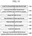
- Another exemplary embodiment of the present invention provides a method for repairing pitch bearings of a wind turbine using the above-described apparatus for moving blades for the wind turbine, the method including: (a) locating first and second blades higher than a third blade (S101); (b) connecting a pair of wires between first and third wire connectors and between second and third wire connectors (S102); (c) removing a third blade from a hub (S103); (d) moving the third blade in a direction away from the hub by changing a pitch of the first and second blades (S104); (e) rotating the pitch bearing of the third blade (S105); (f) moving the third blade in a direction toward the hub (S106); (g) connecting the third blade to the hub (S107); and (h) removing the pair of wires from between the first and third wire connectors and from between the second and third wire connectors (S108).
- the first blade and the second blade may be placed bilaterally symmetrically with respect to the third blade.
- the first wire and the second wire may be placed bilaterally symmetrically with respect to the vertical central axis of the wind turbine.
- the pitch of the first blade and the pitch of the second blade may be turned in opposite directions to move the third blade downward.
- blades of a wind turbine can be easily moved.
- a pitch bearing of a wind turbine can be easily repaired using an apparatus for moving blades of a wind turbine.
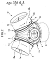
- FIG. 2 is a partial perspective view of a wind turbine equipped with an apparatus for moving blades of the wind turbine according to an exemplary embodiment of the present invention.
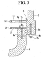
- FIG. 3 is a cross-sectional view of portion A in FIG. 2 .
- FIG. 4 is an enlarged view of portion A in FIG. 2 .
- FIG. 5 is a partial plan view of FIG. 2 as viewed from above.
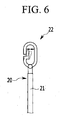
- FIG. 6 is a view illustrating one end of a wire installed at a wire connector of an apparatus for moving blades for a wind turbine according to an exemplary embodiment of the present invention.
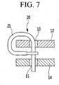
- FIG. 7 is a view illustrating one end of a wire being installed at a wire connector of an apparatus for moving blades for a wind turbine according to an exemplary embodiment of the present invention.
- the wind turbine includes first to third blades 5a, 5b, and 5c clockwise from top left in FIG. 2 .
- Wire connectors 11 to be installed at the first to third blades 5a, 5b, and 5c are hereinafter referred to as first to third wire connectors 11 a, 11 b, and 11c.
- the wire connectors 11 collectively refer to all wire connectors 11 unless they are specified as the first to third wire connectors 11 a, 11 b, and 11 c.
- a blade moving apparatus 10 is a device capable of removing blades 5 of a wind turbine 1 from a hub, with the blades 5 hanging in the air, and moving them up and down.
- the blade moving apparatus 10 of the wind turbine 1 according to an exemplary embodiment of the present invention can be used when removing the blades 5 from the hub 4 and then connecting them again to the hub 4, in order to move the area of contact between internal gears and the inner rings of pitch bearings for turning the pitch of the blades 5 from one side of the inner rings of the pitch bearings, for example, a first section, to the other side of the inner rings, for example, second to fourth sections.
- the blade moving apparatus 10 includes the wire connectors 11 formed at root portions 6 of the blades 5 and a pair of wires 20.
- the pair of wires 20 are formed to be attachable and detachable to and from the first to third wire connectors 11 a, 11 b, and 11c so as to interconnect the first and second wire connectors 11 a and 11 b formed at the first and second blades 5a and 5b located on the upper side and the third wire connector 11c formed at the third blade 5c located on the lower side.
- the wire connectors 11 of the blade moving apparatus 10 are portions to which the wires 20 can be connected that are formed at the root portions 6 of the blades 5, i.e., the ends of the blades 5 adjacent to the hub 4.
- the wire connectors 11 may be respectively formed at the plurality of blades 5a, 5b, and 5c that are connected to the hub 4 of the wind turbine 1.
- the wire connectors 11 include first protrusions 12 and second protrusions 14.
- the first protrusions 12 and the second protrusions 14 may be formed in pairs, and a pair of first protrusions 12 and a pair of second protrusions 14 are arranged at 180-degree intervals at the blade 5 and the root portion 6, respectively,
- first protrusions 12 and second protrusions 14 may be formed in pairs, three or more first protrusions 12 and three or more second protrusions 14 may be formed.
- a first protrusion 12 is made of a plate-like member that extends outward of the blade 5 from the outer periphery of the root portion 6 of the blade 5.
- the first protrusion 12 may be formed by joining a plate-like member, which is formed separately from the blade 5, to the blade 5 by a joining method such as bonding.
- a first hole 13 is formed in the first protrusion 12.
- the first hole 13 is a component for passing the wire 20 through, and is configured to be open in a direction parallel to the direction where the blade 5 extends.
- the first protrusion 12 is joined to the blade 5, it is formed to be rotatable together with the blade 5 as the blade 5 rotates.
- the second protrusion 14 is formed at the hub 4, in parallel with the first protrusion 12. Referring to FIG. 3 , the second protrusion 14 may be secured to a bolt 7a by a fastening member such as a nut 8a when the bolt 7a protruding from the outer ring 9a of a pitch bearing in the direction where the blade 5 extends is fitted to a hole formed at one side of the second protrusion 14.
- a fastening member such as a nut 8a when the bolt 7a protruding from the outer ring 9a of a pitch bearing in the direction where the blade 5 extends is fitted to a hole formed at one side of the second protrusion 14.
- a second hole 15 is likewise formed in the second protrusion 14, in parallel with the first protrusion 12.
- the second hole 15 of the second protrusion 14 may be used for the purpose of guiding the wire 20 in the process of repairing the pitch bearing of the blade 5.
- the second protrusions 14 are fixed in position on the horizontal center line C of the blade 5 in a direction parallel to the front of the blade 5 to which the wind blows.
- the reason why the second protrusions 14 are located on the horizontal center line C of the blade root portion 6 is to prevent the center of gravity of the blade 5 from being eccentric while the blade 5 is hanging by the pair of wires 20a and 20b by making the wire 20 support the blade 5 at the center in a front-back direction of the blade 5 when the wire 20, extended through the second protrusions 14, supports both sides of the blade 5.
- Each of the pair of wires 20 includes a longitudinally extended wire body 21 and a coupling loop 22 at the end of the wire body 21.
- the wire body 21 may be made of a line of a plurality of twisted wires that are rigid enough to support the blade 5 which is heavy.
- the coupling loop 22 may be made of a known loop-shaped fastening member of which one side can be elastically opened and closed.
- the ends of the pair of wires 20 may be connected to the wire connectors 11 in such a manner that the coupling loop 22 of the wire 20 passing through the first hole 13 is fastened to one side of the wire not passing through the first hole 13, with the coupling loop 22 being turned from outside the first protrusion 12.
- the position of the wire 20 may be moved along with the blade 5 when the blade 5 rotates.
- FIG. 8 is a view illustrating wires 20 being installed at wire connectors 11 of a blade moving apparatus 10 of a wind turbine 1 according to an exemplary embodiment of the present invention.
- FIG. 8 is a view of the hub of the wind turbine as viewed from the rear.
- the wires 20 are installed at the wire connectors 11 in order to repair the pitch bearings of the wind turbine by using the blade moving apparatus 10 of the wind turbine according to an exemplary embodiment of the present invention.
- the first blade 5a and the second blade 5b are located above the third blade 5c.
- the first blade 5a and the second blade 5b are arranged to be bilaterally symmetrical with respect to the hub 4, and the third blade 5c is placed in an up-down direction perpendicular to the bottom surface of the third blade 5c.
- the pitch bearing of the third blade 5c can be repaired using the blade moving apparatus 10. If it is desired to repair the first blade 5a, a repair on the first blade 5a can be carried out after locating the first blade 5a on the lower side and locating the second and third blades 5b and 5c above the first blade 5a to be bilaterally symmetrical.
- the pair of wires 20a and 20b are connected between the first and third wire connectors 11 a and 11 c of the first and third blades 5a and 5c and between the second and third wire connectors 11b and 11c of the second and third blades 5b and 5c.
- the wire to be connected between the first and third wire connectors 11 a and 11c is referred to as a first wire 20a
- the wire to be connected between the second and third wire connectors 11 b and 11 c is referred to as a second wire 20b.
- the upper end of the first wire 20a is connected to the first protrusion 12 of the first wire connector 11a located on the upper side, and the lower end of the first wire 20a is connected to the first protrusion 12 of the third wire connector 11 c formed at the left side of the third blade 5c as viewed from FIG. 8 .
- the first protrusion 12 on the upper side is located above the blade root portion 6.
- the reason why the first wire 20a is connected to the first protrusion 12 of the first wire connector 11 a located on the upper side is to make the first wire 20a longer while the first wire 20a is connected between the first wire connector 11 a and the third wire connector 11 c.
- the third blade 5c connected to the first wire 20a is moved downward by rotating the first blade 5a while the first wire 20a is connected to the first wire connector 11 a.
- the first wire 20a should be made longer to keep the moving distance of the third blade 5c sufficiently long.
- the third blade 5c may not be moved smoothly because the first wire 20a is too short.
- the upper end of the first wire 20a is extended downward from the first protrusion 12 of the first wire connector 11 a without passing through the second protrusion 14 when connected to the first protrusion 12, and the lower end of the first wire 20a is connected to the first protrusion 12 of the third wire connector 11 c on the left side of the third blade 5c after passing through the second hole 15 formed at the second protrusion 14.
- the first wire 20a connected between the first wire connector 11 a and the third wire connector 11c to maintain tension between the first wire connector 11 a and the third wire connector 11 c.
- the second wire 20b connected between the second wire connector 11 b and the third wire connector 11c is connected to the first protrusion 12 of the second wire connector 11 b located on the upper side and the first protrusion 12 of the third wire connector 11 c formed on the right side of the third blade 5c.
- the first wire 20a and the second wire 20b are equal in length.
- the first wire 20a and the second wire 20b should be equal in length in order to make the third blade 5c move bilaterally symmetrically, thereby facilitating the movement of the third blade 5c without making the center of gravity eccentric.
- the first and second wires 20a and 20b connected between the first and third wire connectors 11a and 11c and between the second and third wire connectors 11 b and 11 c are arranged to not cross each other.
- the first wire 20a and the second wire 20b are formed to be bilaterally symmetrical with respect to the center of vertical rotation of the blades.
- the first wire 20a and the second wire 20b should be formed to be bilaterally symmetrical in order to move the third blade 5c up and down in a stable way without shifting the center of gravity of the third blade 5c to the left or right.
- FIG. 9 is a view illustrating wires being installed at wire connectors of a blade moving apparatus of a wind turbine according to another exemplary embodiment of the present invention.
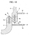
- FIG. 10 is a cross-sectional view of wire connectors of a blade moving apparatus of a wind turbine according to another exemplary embodiment of the present invention.
- the first protrusions 12 and second protrusions 14 of the wire connectors 11 may be located inside the blades 5 and the hub 4.
- the blade moving apparatus 10' of the power turbine 1 has the same configuration as the foregoing exemplary embodiment, except that the first to third wire connectors 11 a, 11 b, and 11 c are located inside the blades 5 and hub 4 of the power turbine 1.
- first protrusions 12 and second protrusions 14 of the first to third wire connectors 11 a to 11 c are formed on the inner peripheral surfaces of the blades 5 and the inner sides of the hub 4, the first wire 20a connected between the first and third wire connectors 11 a and 11 c and the second wire 20b connected between the second and third wire connectors 11 b and 11 c are located inside the blades 5 and the hub 4.
- configuring the blade moving apparatus 10' according to another exemplary embodiment of the present invention enables a worker to carry out the connection of the first wire 20a and the second wire 20b within the power turbine without going out of the blades 5 and the hub 4.
- FIG. 11 is a flowchart of a method for repairing pitch bearings of a wind turbine according to an exemplary embodiment of the present invention.
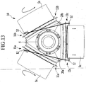
- FIG. 12 to FIG. 17 are views illustrating a process of repairing pitch bearings of a wind turbine using a blade moving apparatus of the wind turbine according to an exemplary embodiment of the present invention.
- FIG. 12 to FIG. 17 are views of the hub and blade root portions of the wind turbine as viewed from the rear.
- the method for repairing pitch bearings of a wind turbine includes:
- the first and second blades 5a and 5b are first located higher than the third blade 5c as shown in FIG. 12 (S101).
- the reason why the first and second blades 5a and 5b are located higher than the third blade 5c is to make the third blade 5c hang on the first wire 20a and the second wire 20b by connecting the upper ends of the first wire 20a and second wire 20b to the first wire connector 11 a of the first blade 5a and the second wire connector 11 b of the second blade 5b, respectively, and connecting the lower ends of the first wire 20a and second wire 20b to the third wire connector 11c of the third blade 5c.
- the third blade 5c is arranged perpendicular to the bottom of the hub, and the first blade 5a and the second blade 5b located above the third blade 5c are placed bilaterally symmetrically with respect to the third blade 5c.
- the first wire 20a and the second wire 20b are connected between the first and third wire connectors 11a and 11c and between the second and third wire connectors 11b and 11c, respectively (S102).
- the first wire 20a and the second wire 20b are formed to be bilaterally symmetrical with respect to the vertical central axis of the wind turbine.
- the third blade 5c is removed from the hub 4 (S103).
- the process of removing the third blade 5c from the hub 4 can be carried out by removing a nut 8b for coupling the third blade 5c to a pitch bearing inner ring 9b of the hub 4 from a bolt 7b.
- the third blade 5c remains hanging in the air by the first wire 20a and the second wire 20b.
- FIG. 13 depicts the third blade 5c hanging in the air by the first wire 20a and the second wire 20b. While the third blade 5c is hanging in the air by the first wire 20a and the second wire 20b, the third blade 5c is moved downward, i.e., in a direction away from the hub (S104).
- the pitch of the first blade 5a and the pitch of the second blade 5b are turned in opposite directions to move the third blade 5c downward. Referring to FIG. 14 , rotating the first blade 5a clockwise and rotating the second blade 5b counterclockwise cause the third blade 5c hanging on the first wire 20a and the second wire 20b to move downward and away from the hub.
- the third blade 5c only needs to be moved a short distance, not far away from the hub 4.
- the angle of rotation of the inner ring gear may range between 90 to 270 degrees.
- the area of contact between the inner ring gear of the pitch bearing and the inner ring of the pitch bearing is moved from the first section of the inner ring to the second to fourth sections.
- the first blade 5a and the second blade 5b are rotated backward as shown in FIG. 16 , thereby moving the third blade 5c back in a direction toward the hub 4 (S106).
- the repair of the pitch bearing of the third bearing 5c is completed by removing the first and second wires 20a and 20b from between the first and third wire connectors 11 a and 11c and from between the second and third wire connectors 11 b and 11 c (S108).
- the pitch bearings can be repaired while the blades are moved away from the hub, for example, while the blades are located near the hub, without being lowered to the ground where the wind turbine is installed. Therefore, the repair time of the pitch bearings of the wind turbine can be reduced and the repair procedure can be simplified.
- an exemplary embodiment of the present invention illustrates using a blade moving apparatus with wire connectors and wires for the purpose of repairing pitch bearings of a wind turbine
- the blade moving apparatus may be readily used when there is a need to remove the blades for the wind turbine from the hub or when maintaining and repairing the wind turbine, apart from the embodiment described in this specification.
- the blades for the wind turbine can be simply and easily moved.
- the pitch bearings of the wind turbine can be simply repaired using the blade moving apparatus of the wind turbine.
Landscapes
- Engineering & Computer Science (AREA)
- Life Sciences & Earth Sciences (AREA)
- Sustainable Development (AREA)
- Sustainable Energy (AREA)
- Chemical & Material Sciences (AREA)
- Combustion & Propulsion (AREA)
- Mechanical Engineering (AREA)
- General Engineering & Computer Science (AREA)
- Physics & Mathematics (AREA)
- Fluid Mechanics (AREA)
- Wind Motors (AREA)
Claims (13)
- Vorrichtung zur Bewegung von Rotorblättern einer Windturbine (1) mit einer Nabe (4) und einer Mehrzahl von Rotorblättern (5), die an der Nabe angebracht sind, wobei die Vorrichtung Folgendes umfasst:Drahtverbinder (11), die jeweils erste Vorsprünge (12), die an Wurzelabschnitten (6) der ersten bis dritten Rotorblätter bereitgestellt sind, und zweite Vorsprünge (14), die an der Nabe (4) bereitgestellt sind, umfassen, um parallel mit den ersten Vorsprüngen angeordnet zu sein; undein Paar von Drähten (20), die an ersten bis dritten Drahtverbindern (11) befestigt und davon entfernt werden können,wobei jeder der ersten Vorsprünge (12) ein erstes Loch aufweist, an die die Drähte angeschlossen sind, und jeder der zweiten Vorsprünge (14) ein zweites Loch aufweist, um die Drähte zu führen.
- Vorrichtung nach Anspruch 1, wobei die ersten Vorsprünge (12) in Paaren gebildet sind.
- Vorrichtung nach Anspruch 2, wobei das Paar von ersten Vorsprüngen (12) an einer äußeren oder inneren Umfangsfläche des Wurzelabschnitts (6) des Rotorblatts gebildet ist.
- Vorrichtung nach Anspruch 3, wobei die ersten Löcher, die im Paar von ersten Vorsprüngen (12) gebildet sind, in einer Richtung parallel zur Richtung, in der sich das Rotorblatt (5) erstreckt, geöffnet sind.
- Vorrichtung nach Anspruch 1, wobei die zweiten Vorsprünge (14) in Position auf einer horizontalen Mittellinie der Rotorblätter in einer Richtung parallel zur Vorderseite der Wurzelabschnitte der Rotorblätter (5) fixiert sind.
- Vorrichtung nach Anspruch 5, wobei das Paar von Drähten, das an die ersten und zweiten Drahtanschlüsse (11) angeschlossen werden soll, mit einem Paar von ersten Vorsprüngen (12) der ersten und zweiten Drahtanschlüsse angeschlossen sind, die sich auf der oberen Seite befinden.
- Vorrichtung nach Anspruch 5, wobei das Paar von Drähten, das an das Paar von ersten Vorsprüngen (12) der ersten und zweiten Drahtanschlüsse (11) angeschlossen ist, an ein Paar von Vorsprüngen des dritten Drahtanschlusses angeschlossen ist.
- Vorrichtung nach Anspruch 5, wobei das Paar von Drähten (20) ausgelegt ist, um durch die zweiten Löcher der dritten Drahtanschlüsse zu verlaufen.
- Vorrichtung nach Anspruch 1, wobei das Paar von Drähten (20), das zwischen den ersten und dritten Drahtanschlüssen und zwischen den zweiten und dritten Drahtanschlüssen angeschlossen ist, angeordnet ist, um einander nicht zu kreuzen.
- Vorrichtung nach Anspruch 1, wobei Kopplungsschleifen an gegenüberliegenden Enden des Paars von Drähten gebildet sind.
- Windturbine (1), umfassend die Vorrichtung nach einem der Ansprüche 1 bis 10.
- Verfahren zur Reparatur von Blattlagern einer Windturbine unter Verwendung der Vorrichtung nach einem der Ansprüche 1 bis 10, wobei das Verfahren Folgendes umfasst:(a) Anordnen der ersten und zweiten Rotorblätter (5a, 5b) über einem dritten Rotorblatt;(b) Anschließen eines Paars von Drähten (20) zwischen ersten und dritten Drahtanschlüssen und zwischen zweiten und dritten Drahtanschlüssen;(c) Entfernen eines dritten Rotorblatts (5c) von einer Nabe (4);(d) Bewegen des dritten Rotorblatts (5c) in einer Richtung weg von der Nabe durch das Ändern eines Blatts der ersten zweiten Rotorblätter;(e) Drehen des Blattlagers des dritten Rotorblatts;(f) Bewegen des dritten Rotorblatts (5c) in einer Richtung hin zur Nabe;(g) Anschließen des dritten Rotorblatts an die Nabe (4); und(h) Entfernen des Paars von Drähten (20) von zwischen den ersten und dritten Drahtanschlüssen und von zwischen den zweiten und dritten Drahtanschlüssen.
- Verfahren nach Anspruch 12, wobei in (d) und (f) das Blatt des ersten Rotorblatts und das Blatt des zweiten Rotorblatts (5a, 5b) in entgegengesetzte Richtungen gedreht werden, um das dritte Rotorblatt nach unten zu bewegen.
Applications Claiming Priority (2)
| Application Number | Priority Date | Filing Date | Title |
|---|---|---|---|
| KR1020120005260A KR101362936B1 (ko) | 2012-01-17 | 2012-01-17 | 풍력발전기의 블레이드 이동 장치, 이를 이용한 피치 베어링 수리 방법 및 이를 구비한 풍력 발전기 |
| PCT/KR2013/000326 WO2013109046A1 (ko) | 2012-01-17 | 2013-01-16 | 풍력발전기의 블레이드 이동 장치, 이를 이용한 피치 베어링 수리 방법 및 이를 구비한 풍력 발전기 |
Publications (3)
| Publication Number | Publication Date |
|---|---|
| EP2806155A1 EP2806155A1 (de) | 2014-11-26 |
| EP2806155A4 EP2806155A4 (de) | 2015-09-02 |
| EP2806155B1 true EP2806155B1 (de) | 2016-10-12 |
Family
ID=48799424
Family Applications (1)
| Application Number | Title | Priority Date | Filing Date |
|---|---|---|---|
| EP13738768.4A Not-in-force EP2806155B1 (de) | 2012-01-17 | 2013-01-16 | Vorrichtung zur Bewegung eines Rotorblatts einer Windturbine, Verfahren zur Reparatur des Blattlagers damit und Windturbine damit |
Country Status (4)
| Country | Link |
|---|---|
| US (1) | US9810197B2 (de) |
| EP (1) | EP2806155B1 (de) |
| KR (1) | KR101362936B1 (de) |
| WO (1) | WO2013109046A1 (de) |
Cited By (2)
| Publication number | Priority date | Publication date | Assignee | Title |
|---|---|---|---|---|
| US10801473B2 (en) | 2017-03-29 | 2020-10-13 | General Electric Company | Hub crane assembly for a wind turbine |
| US11480148B2 (en) | 2017-11-16 | 2022-10-25 | Wobben Properties Gmbh | Connection of a rotor blade to the rotor hub of a wind turbine |
Families Citing this family (8)
| Publication number | Priority date | Publication date | Assignee | Title |
|---|---|---|---|---|
| US9745953B2 (en) * | 2012-10-23 | 2017-08-29 | General Electric Company | Method and system for replacing a single wind turbine blade |
| KR101508623B1 (ko) * | 2013-11-22 | 2015-04-08 | 삼성중공업 주식회사 | 풍력 발전기용 로터의 리프팅 장치 및 이를 이용한 로터의 설치 방법 |
| WO2017108052A1 (en) * | 2015-12-22 | 2017-06-29 | Vestas Wind Systems A/S | A method and a system for mounting a rotor to a drive shaft of a wind turbine |
| EP3263888B1 (de) | 2016-06-30 | 2023-10-04 | Siemens Gamesa Renewable Energy A/S | Verfahren zur handhabung einer windturbinenrotorblattanstelllagereinheit |
| WO2018120081A1 (en) * | 2016-12-30 | 2018-07-05 | General Electric Company | Hub-to-shaft adapter for a rotor assembly of a wind turbine and related assembly methods |
| US10502195B2 (en) * | 2017-04-27 | 2019-12-10 | General Electric Company | Clamping apparatus for securing a main bearing of a wind turbine during an installation and/or repair procedure |
| DE102018130895A1 (de) | 2018-12-04 | 2020-06-04 | Wobben Properties Gmbh | Rotor für eine Windenergieanlage und Verfahren |
| CN112814837A (zh) * | 2021-01-20 | 2021-05-18 | 东方电气风电有限公司 | 一种风电机组螺栓连接结构、叶根结构、风电叶片及机组 |
Family Cites Families (14)
| Publication number | Priority date | Publication date | Assignee | Title |
|---|---|---|---|---|
| ES2295398T3 (es) | 2001-07-20 | 2008-04-16 | Aloys Wobben | Procedimiento para la construccion in situ de una instalacion de energia eolica. |
| DE10224439C5 (de) * | 2002-06-01 | 2009-12-31 | Aloys Wobben | Verfahren zur Montage/Demontage von Komponenten einer Windenergieanlage |
| DE102004056340B4 (de) | 2004-11-22 | 2010-11-18 | Repower Systems Ag | Vorrichtung und Verfahren zur Montage und/oder Demontage eines Bauteils einer Windkraftanlage |
| NO326268B1 (no) | 2007-03-14 | 2008-10-27 | Vidar Holmoy | Vindkraftverkrotor. |
| JP5055023B2 (ja) | 2007-05-25 | 2012-10-24 | 三菱重工業株式会社 | 風力発電装置のロータ取付け方法および風力発電装置の建設方法 |
| US20100139062A1 (en) | 2009-02-25 | 2010-06-10 | General Electric Company | Lowering and raising a single wind turbine rotor blade from six-o'clock position |
| US8091199B2 (en) | 2009-03-19 | 2012-01-10 | General Electric Company | Method to repair pitch control components |
| KR101054919B1 (ko) * | 2009-04-03 | 2011-08-05 | 주식회사 디엠에스 | 풍력 발전기 |
| FR2946700B1 (fr) | 2009-06-15 | 2018-07-20 | Soletanche Freyssinet | Procede, systeme et dispositif pour contribuer a l'assemblage d'une eolienne. |
| US20100143136A1 (en) | 2009-08-31 | 2010-06-10 | Jeffrey Michael Daniels | Systems and methods for assembling a pitch assembly for use in a wind turbine |
| US8092171B2 (en) | 2009-09-30 | 2012-01-10 | General Electric Company | Systems and methods for assembling a pitch assembly for use in a wind turbine |
| US8118552B2 (en) * | 2009-10-06 | 2012-02-21 | General Electric Company | Apparatus and method for manipulating a component of a wind turbine |
| WO2011095167A2 (en) * | 2010-02-08 | 2011-08-11 | Okutan Ufuk | A method for lifting and lowering of a wind turbine blade |
| JP4699571B1 (ja) * | 2010-08-31 | 2011-06-15 | 三菱重工業株式会社 | 風力発電装置の保守方法 |
-
2012
- 2012-01-17 KR KR1020120005260A patent/KR101362936B1/ko active IP Right Grant
-
2013
- 2013-01-16 EP EP13738768.4A patent/EP2806155B1/de not_active Not-in-force
- 2013-01-16 WO PCT/KR2013/000326 patent/WO2013109046A1/ko active Application Filing
- 2013-01-16 US US14/372,740 patent/US9810197B2/en active Active
Cited By (2)
| Publication number | Priority date | Publication date | Assignee | Title |
|---|---|---|---|---|
| US10801473B2 (en) | 2017-03-29 | 2020-10-13 | General Electric Company | Hub crane assembly for a wind turbine |
| US11480148B2 (en) | 2017-11-16 | 2022-10-25 | Wobben Properties Gmbh | Connection of a rotor blade to the rotor hub of a wind turbine |
Also Published As
| Publication number | Publication date |
|---|---|
| EP2806155A1 (de) | 2014-11-26 |
| US9810197B2 (en) | 2017-11-07 |
| EP2806155A4 (de) | 2015-09-02 |
| KR101362936B1 (ko) | 2014-02-14 |
| KR20130084458A (ko) | 2013-07-25 |
| US20150300313A1 (en) | 2015-10-22 |
| WO2013109046A1 (ko) | 2013-07-25 |
Similar Documents
| Publication | Publication Date | Title |
|---|---|---|
| EP2806155B1 (de) | Vorrichtung zur Bewegung eines Rotorblatts einer Windturbine, Verfahren zur Reparatur des Blattlagers damit und Windturbine damit | |
| US8528735B2 (en) | Transport frame for nacelle/rotor hub unit of a wind turbine, method of transporting and mounting a nacelle/rotor hub unit | |
| ES2322000B1 (es) | Un metodo para montar el rotor de un aerogenerador. | |
| JP4551491B1 (ja) | 風力発電装置のロータヘッド内機器昇降方法 | |
| EP2433001B1 (de) | Nabe für eine windturbine | |
| CA2665147A1 (en) | Wind-turbine rotor-blade hoisting apparatus, method for attaching wind-turbine rotor blade, and method for constructing wind power generator | |
| JP5410172B2 (ja) | 浮体式洋上風車 | |
| US20180023543A1 (en) | A wind turbine comprising two or more rotors | |
| CN103562547B (zh) | 自然能量取出装置 | |
| US8171614B2 (en) | Systems and method of assembling a tower section | |
| EP3431751B1 (de) | System und verfahren zur uptower-aufhängung einer rotorschaufel einer windturbine | |
| CA2666441A1 (en) | Method for attaching rotor of wind turbine generator and method for constructing wind turbine generator | |
| AU2008229709A1 (en) | Method for mounting rotor blades and rotor blade for a wind turbine | |
| KR101338407B1 (ko) | 풍력발전기 블레이드의 이동장치 | |
| US10260483B2 (en) | Fixation device for servicing wind turbine components | |
| WO2012062352A1 (en) | Lifting beam for use in hoisting a wind turbine blade | |
| CN103052792A (zh) | 垂直轴风轮机 | |
| JP2005320919A (ja) | 風車翼、及び、それの塔上取付方法 | |
| US10823138B2 (en) | Counterweight assembly for use during single blade installation of a wind turbine | |
| CN104314751A (zh) | 一种垂直轴风力机及具有其的风能船 | |
| JP4547039B1 (ja) | 風力発電用ローターブレードの取り付け方法 | |
| EP3167186A1 (de) | Errichtung eines grossen windturbinenturms mit kletterkran | |
| KR101168793B1 (ko) | 가변텐션스프링을 이용한 풍차허브 | |
| KR101358232B1 (ko) | 풍력발전기용 블레이드 설치장치 및 이를 이용한 풍력발전기용 블레이드 설치방법 | |
| KR101517887B1 (ko) | 풍력발전기의 타워 세그먼트용 인양 지그 |
Legal Events
| Date | Code | Title | Description |
|---|---|---|---|
| PUAI | Public reference made under article 153(3) epc to a published international application that has entered the european phase |
Free format text: ORIGINAL CODE: 0009012 |
|
| 17P | Request for examination filed |
Effective date: 20140721 |
|
| AK | Designated contracting states |
Kind code of ref document: A1 Designated state(s): AL AT BE BG CH CY CZ DE DK EE ES FI FR GB GR HR HU IE IS IT LI LT LU LV MC MK MT NL NO PL PT RO RS SE SI SK SM TR |
|
| DAX | Request for extension of the european patent (deleted) | ||
| RA4 | Supplementary search report drawn up and despatched (corrected) |
Effective date: 20150805 |
|
| RIC1 | Information provided on ipc code assigned before grant |
Ipc: F03D 1/00 20060101AFI20150730BHEP Ipc: F03D 11/00 20060101ALI20150730BHEP |
|
| GRAP | Despatch of communication of intention to grant a patent |
Free format text: ORIGINAL CODE: EPIDOSNIGR1 |
|
| RIC1 | Information provided on ipc code assigned before grant |
Ipc: F03D 1/00 20060101AFI20160412BHEP Ipc: F03D 80/00 20160101ALI20160412BHEP |
|
| INTG | Intention to grant announced |
Effective date: 20160509 |
|
| GRAS | Grant fee paid |
Free format text: ORIGINAL CODE: EPIDOSNIGR3 |
|
| GRAA | (expected) grant |
Free format text: ORIGINAL CODE: 0009210 |
|
| AK | Designated contracting states |
Kind code of ref document: B1 Designated state(s): AL AT BE BG CH CY CZ DE DK EE ES FI FR GB GR HR HU IE IS IT LI LT LU LV MC MK MT NL NO PL PT RO RS SE SI SK SM TR |
|
| REG | Reference to a national code |
Ref country code: GB Ref legal event code: FG4D |
|
| REG | Reference to a national code |
Ref country code: CH Ref legal event code: EP |
|
| REG | Reference to a national code |
Ref country code: AT Ref legal event code: REF Ref document number: 836762 Country of ref document: AT Kind code of ref document: T Effective date: 20161015 |
|
| REG | Reference to a national code |
Ref country code: IE Ref legal event code: FG4D |
|
| REG | Reference to a national code |
Ref country code: DE Ref legal event code: R096 Ref document number: 602013012722 Country of ref document: DE |
|
| REG | Reference to a national code |
Ref country code: LT Ref legal event code: MG4D |
|
| REG | Reference to a national code |
Ref country code: NL Ref legal event code: MP Effective date: 20161012 |
|
| PG25 | Lapsed in a contracting state [announced via postgrant information from national office to epo] |
Ref country code: LV Free format text: LAPSE BECAUSE OF FAILURE TO SUBMIT A TRANSLATION OF THE DESCRIPTION OR TO PAY THE FEE WITHIN THE PRESCRIBED TIME-LIMIT Effective date: 20161012 |
|
| REG | Reference to a national code |
Ref country code: AT Ref legal event code: MK05 Ref document number: 836762 Country of ref document: AT Kind code of ref document: T Effective date: 20161012 |
|
| PG25 | Lapsed in a contracting state [announced via postgrant information from national office to epo] |
Ref country code: GR Free format text: LAPSE BECAUSE OF FAILURE TO SUBMIT A TRANSLATION OF THE DESCRIPTION OR TO PAY THE FEE WITHIN THE PRESCRIBED TIME-LIMIT Effective date: 20170113 Ref country code: NO Free format text: LAPSE BECAUSE OF FAILURE TO SUBMIT A TRANSLATION OF THE DESCRIPTION OR TO PAY THE FEE WITHIN THE PRESCRIBED TIME-LIMIT Effective date: 20170112 Ref country code: SE Free format text: LAPSE BECAUSE OF FAILURE TO SUBMIT A TRANSLATION OF THE DESCRIPTION OR TO PAY THE FEE WITHIN THE PRESCRIBED TIME-LIMIT Effective date: 20161012 Ref country code: LT Free format text: LAPSE BECAUSE OF FAILURE TO SUBMIT A TRANSLATION OF THE DESCRIPTION OR TO PAY THE FEE WITHIN THE PRESCRIBED TIME-LIMIT Effective date: 20161012 |
|
| PG25 | Lapsed in a contracting state [announced via postgrant information from national office to epo] |
Ref country code: FI Free format text: LAPSE BECAUSE OF FAILURE TO SUBMIT A TRANSLATION OF THE DESCRIPTION OR TO PAY THE FEE WITHIN THE PRESCRIBED TIME-LIMIT Effective date: 20161012 Ref country code: NL Free format text: LAPSE BECAUSE OF FAILURE TO SUBMIT A TRANSLATION OF THE DESCRIPTION OR TO PAY THE FEE WITHIN THE PRESCRIBED TIME-LIMIT Effective date: 20161012 Ref country code: RS Free format text: LAPSE BECAUSE OF FAILURE TO SUBMIT A TRANSLATION OF THE DESCRIPTION OR TO PAY THE FEE WITHIN THE PRESCRIBED TIME-LIMIT Effective date: 20161012 Ref country code: AT Free format text: LAPSE BECAUSE OF FAILURE TO SUBMIT A TRANSLATION OF THE DESCRIPTION OR TO PAY THE FEE WITHIN THE PRESCRIBED TIME-LIMIT Effective date: 20161012 Ref country code: ES Free format text: LAPSE BECAUSE OF FAILURE TO SUBMIT A TRANSLATION OF THE DESCRIPTION OR TO PAY THE FEE WITHIN THE PRESCRIBED TIME-LIMIT Effective date: 20161012 Ref country code: BE Free format text: LAPSE BECAUSE OF FAILURE TO SUBMIT A TRANSLATION OF THE DESCRIPTION OR TO PAY THE FEE WITHIN THE PRESCRIBED TIME-LIMIT Effective date: 20161012 Ref country code: PL Free format text: LAPSE BECAUSE OF FAILURE TO SUBMIT A TRANSLATION OF THE DESCRIPTION OR TO PAY THE FEE WITHIN THE PRESCRIBED TIME-LIMIT Effective date: 20161012 Ref country code: IS Free format text: LAPSE BECAUSE OF FAILURE TO SUBMIT A TRANSLATION OF THE DESCRIPTION OR TO PAY THE FEE WITHIN THE PRESCRIBED TIME-LIMIT Effective date: 20170212 Ref country code: PT Free format text: LAPSE BECAUSE OF FAILURE TO SUBMIT A TRANSLATION OF THE DESCRIPTION OR TO PAY THE FEE WITHIN THE PRESCRIBED TIME-LIMIT Effective date: 20170213 Ref country code: HR Free format text: LAPSE BECAUSE OF FAILURE TO SUBMIT A TRANSLATION OF THE DESCRIPTION OR TO PAY THE FEE WITHIN THE PRESCRIBED TIME-LIMIT Effective date: 20161012 |
|
| REG | Reference to a national code |
Ref country code: DE Ref legal event code: R097 Ref document number: 602013012722 Country of ref document: DE |
|
| PG25 | Lapsed in a contracting state [announced via postgrant information from national office to epo] |
Ref country code: RO Free format text: LAPSE BECAUSE OF FAILURE TO SUBMIT A TRANSLATION OF THE DESCRIPTION OR TO PAY THE FEE WITHIN THE PRESCRIBED TIME-LIMIT Effective date: 20161012 Ref country code: CZ Free format text: LAPSE BECAUSE OF FAILURE TO SUBMIT A TRANSLATION OF THE DESCRIPTION OR TO PAY THE FEE WITHIN THE PRESCRIBED TIME-LIMIT Effective date: 20161012 Ref country code: SK Free format text: LAPSE BECAUSE OF FAILURE TO SUBMIT A TRANSLATION OF THE DESCRIPTION OR TO PAY THE FEE WITHIN THE PRESCRIBED TIME-LIMIT Effective date: 20161012 Ref country code: EE Free format text: LAPSE BECAUSE OF FAILURE TO SUBMIT A TRANSLATION OF THE DESCRIPTION OR TO PAY THE FEE WITHIN THE PRESCRIBED TIME-LIMIT Effective date: 20161012 Ref country code: DK Free format text: LAPSE BECAUSE OF FAILURE TO SUBMIT A TRANSLATION OF THE DESCRIPTION OR TO PAY THE FEE WITHIN THE PRESCRIBED TIME-LIMIT Effective date: 20161012 |
|
| PLBE | No opposition filed within time limit |
Free format text: ORIGINAL CODE: 0009261 |
|
| STAA | Information on the status of an ep patent application or granted ep patent |
Free format text: STATUS: NO OPPOSITION FILED WITHIN TIME LIMIT |
|
| PG25 | Lapsed in a contracting state [announced via postgrant information from national office to epo] |
Ref country code: IT Free format text: LAPSE BECAUSE OF FAILURE TO SUBMIT A TRANSLATION OF THE DESCRIPTION OR TO PAY THE FEE WITHIN THE PRESCRIBED TIME-LIMIT Effective date: 20161012 Ref country code: SM Free format text: LAPSE BECAUSE OF FAILURE TO SUBMIT A TRANSLATION OF THE DESCRIPTION OR TO PAY THE FEE WITHIN THE PRESCRIBED TIME-LIMIT Effective date: 20161012 Ref country code: BG Free format text: LAPSE BECAUSE OF FAILURE TO SUBMIT A TRANSLATION OF THE DESCRIPTION OR TO PAY THE FEE WITHIN THE PRESCRIBED TIME-LIMIT Effective date: 20170112 |
|
| REG | Reference to a national code |
Ref country code: CH Ref legal event code: PL |
|
| 26N | No opposition filed |
Effective date: 20170713 |
|
| PG25 | Lapsed in a contracting state [announced via postgrant information from national office to epo] |
Ref country code: MC Free format text: LAPSE BECAUSE OF FAILURE TO SUBMIT A TRANSLATION OF THE DESCRIPTION OR TO PAY THE FEE WITHIN THE PRESCRIBED TIME-LIMIT Effective date: 20161012 |
|
| REG | Reference to a national code |
Ref country code: FR Ref legal event code: ST Effective date: 20170929 |
|
| PG25 | Lapsed in a contracting state [announced via postgrant information from national office to epo] |
Ref country code: LI Free format text: LAPSE BECAUSE OF NON-PAYMENT OF DUE FEES Effective date: 20170131 Ref country code: CH Free format text: LAPSE BECAUSE OF NON-PAYMENT OF DUE FEES Effective date: 20170131 Ref country code: FR Free format text: LAPSE BECAUSE OF NON-PAYMENT OF DUE FEES Effective date: 20170131 |
|
| REG | Reference to a national code |
Ref country code: IE Ref legal event code: MM4A |
|
| PG25 | Lapsed in a contracting state [announced via postgrant information from national office to epo] |
Ref country code: LU Free format text: LAPSE BECAUSE OF NON-PAYMENT OF DUE FEES Effective date: 20170116 Ref country code: SI Free format text: LAPSE BECAUSE OF FAILURE TO SUBMIT A TRANSLATION OF THE DESCRIPTION OR TO PAY THE FEE WITHIN THE PRESCRIBED TIME-LIMIT Effective date: 20161012 |
|
| PG25 | Lapsed in a contracting state [announced via postgrant information from national office to epo] |
Ref country code: IE Free format text: LAPSE BECAUSE OF NON-PAYMENT OF DUE FEES Effective date: 20170116 |
|
| PG25 | Lapsed in a contracting state [announced via postgrant information from national office to epo] |
Ref country code: MT Free format text: LAPSE BECAUSE OF NON-PAYMENT OF DUE FEES Effective date: 20170116 |
|
| PG25 | Lapsed in a contracting state [announced via postgrant information from national office to epo] |
Ref country code: HU Free format text: LAPSE BECAUSE OF FAILURE TO SUBMIT A TRANSLATION OF THE DESCRIPTION OR TO PAY THE FEE WITHIN THE PRESCRIBED TIME-LIMIT; INVALID AB INITIO Effective date: 20130116 |
|
| PG25 | Lapsed in a contracting state [announced via postgrant information from national office to epo] |
Ref country code: CY Free format text: LAPSE BECAUSE OF FAILURE TO SUBMIT A TRANSLATION OF THE DESCRIPTION OR TO PAY THE FEE WITHIN THE PRESCRIBED TIME-LIMIT Effective date: 20161012 |
|
| PG25 | Lapsed in a contracting state [announced via postgrant information from national office to epo] |
Ref country code: MK Free format text: LAPSE BECAUSE OF FAILURE TO SUBMIT A TRANSLATION OF THE DESCRIPTION OR TO PAY THE FEE WITHIN THE PRESCRIBED TIME-LIMIT Effective date: 20161012 |
|
| PG25 | Lapsed in a contracting state [announced via postgrant information from national office to epo] |
Ref country code: TR Free format text: LAPSE BECAUSE OF FAILURE TO SUBMIT A TRANSLATION OF THE DESCRIPTION OR TO PAY THE FEE WITHIN THE PRESCRIBED TIME-LIMIT Effective date: 20161012 |
|
| PG25 | Lapsed in a contracting state [announced via postgrant information from national office to epo] |
Ref country code: AL Free format text: LAPSE BECAUSE OF FAILURE TO SUBMIT A TRANSLATION OF THE DESCRIPTION OR TO PAY THE FEE WITHIN THE PRESCRIBED TIME-LIMIT Effective date: 20161012 |
|
| PGFP | Annual fee paid to national office [announced via postgrant information from national office to epo] |
Ref country code: GB Payment date: 20201218 Year of fee payment: 9 |
|
| PGFP | Annual fee paid to national office [announced via postgrant information from national office to epo] |
Ref country code: DE Payment date: 20201217 Year of fee payment: 9 |
|
| REG | Reference to a national code |
Ref country code: DE Ref legal event code: R119 Ref document number: 602013012722 Country of ref document: DE |
|
| GBPC | Gb: european patent ceased through non-payment of renewal fee |
Effective date: 20220116 |
|
| PG25 | Lapsed in a contracting state [announced via postgrant information from national office to epo] |
Ref country code: GB Free format text: LAPSE BECAUSE OF NON-PAYMENT OF DUE FEES Effective date: 20220116 Ref country code: DE Free format text: LAPSE BECAUSE OF NON-PAYMENT OF DUE FEES Effective date: 20220802 |