EP2806076A1 - Verfahren und System für retroreflektierende Kühlung - Google Patents
Verfahren und System für retroreflektierende Kühlung Download PDFInfo
- Publication number
- EP2806076A1 EP2806076A1 EP20140161459 EP14161459A EP2806076A1 EP 2806076 A1 EP2806076 A1 EP 2806076A1 EP 20140161459 EP20140161459 EP 20140161459 EP 14161459 A EP14161459 A EP 14161459A EP 2806076 A1 EP2806076 A1 EP 2806076A1
- Authority
- EP
- European Patent Office
- Prior art keywords
- range
- retroreflective elements
- wavelengths
- covering
- corner cube
- Prior art date
- Legal status (The legal status is an assumption and is not a legal conclusion. Google has not performed a legal analysis and makes no representation as to the accuracy of the status listed.)
- Withdrawn
Links
- 238000000034 method Methods 0.000 title description 7
- 238000001816 cooling Methods 0.000 title description 4
- 238000010438 heat treatment Methods 0.000 claims abstract description 15
- 230000002401 inhibitory effect Effects 0.000 claims abstract description 4
- 239000000853 adhesive Substances 0.000 claims description 13
- 230000001070 adhesive effect Effects 0.000 claims description 13
- 239000011324 bead Substances 0.000 claims description 12
- 239000000758 substrate Substances 0.000 claims description 10
- 239000013306 transparent fiber Substances 0.000 claims description 5
- 230000004907 flux Effects 0.000 description 17
- 230000005855 radiation Effects 0.000 description 9
- 238000000576 coating method Methods 0.000 description 7
- 239000000463 material Substances 0.000 description 6
- 238000013459 approach Methods 0.000 description 5
- 230000005670 electromagnetic radiation Effects 0.000 description 5
- 239000004033 plastic Substances 0.000 description 5
- 229920001169 thermoplastic Polymers 0.000 description 5
- 239000004416 thermosoftening plastic Substances 0.000 description 5
- 241000282326 Felis catus Species 0.000 description 4
- 239000011521 glass Substances 0.000 description 4
- 239000011248 coating agent Substances 0.000 description 3
- 239000000835 fiber Substances 0.000 description 3
- 238000009413 insulation Methods 0.000 description 3
- 230000007246 mechanism Effects 0.000 description 3
- 230000003287 optical effect Effects 0.000 description 3
- RSWGJHLUYNHPMX-UHFFFAOYSA-N Abietic-Saeure Chemical class C12CCC(C(C)C)=CC2=CCC2C1(C)CCCC2(C)C(O)=O RSWGJHLUYNHPMX-UHFFFAOYSA-N 0.000 description 2
- XKRFYHLGVUSROY-UHFFFAOYSA-N Argon Chemical compound [Ar] XKRFYHLGVUSROY-UHFFFAOYSA-N 0.000 description 2
- KHPCPRHQVVSZAH-HUOMCSJISA-N Rosin Chemical class O(C/C=C/c1ccccc1)[C@H]1[C@H](O)[C@@H](O)[C@@H](O)[C@@H](CO)O1 KHPCPRHQVVSZAH-HUOMCSJISA-N 0.000 description 2
- 238000010521 absorption reaction Methods 0.000 description 2
- 229910052782 aluminium Inorganic materials 0.000 description 2
- XAGFODPZIPBFFR-UHFFFAOYSA-N aluminium Chemical compound [Al] XAGFODPZIPBFFR-UHFFFAOYSA-N 0.000 description 2
- 230000002457 bidirectional effect Effects 0.000 description 2
- 239000011230 binding agent Substances 0.000 description 2
- 239000000428 dust Substances 0.000 description 2
- 230000000694 effects Effects 0.000 description 2
- 150000002148 esters Chemical class 0.000 description 2
- 239000007789 gas Substances 0.000 description 2
- 238000012423 maintenance Methods 0.000 description 2
- VNWKTOKETHGBQD-UHFFFAOYSA-N methane Chemical compound C VNWKTOKETHGBQD-UHFFFAOYSA-N 0.000 description 2
- 239000003595 mist Substances 0.000 description 2
- 239000003973 paint Substances 0.000 description 2
- 229910052709 silver Inorganic materials 0.000 description 2
- 239000004332 silver Substances 0.000 description 2
- KHPCPRHQVVSZAH-UHFFFAOYSA-N trans-cinnamyl beta-D-glucopyranoside Chemical class OC1C(O)C(O)C(CO)OC1OCC=CC1=CC=CC=C1 KHPCPRHQVVSZAH-UHFFFAOYSA-N 0.000 description 2
- XLYOFNOQVPJJNP-UHFFFAOYSA-N water Substances O XLYOFNOQVPJJNP-UHFFFAOYSA-N 0.000 description 2
- 230000004075 alteration Effects 0.000 description 1
- 229910052786 argon Inorganic materials 0.000 description 1
- 230000005540 biological transmission Effects 0.000 description 1
- 239000004568 cement Substances 0.000 description 1
- 230000002301 combined effect Effects 0.000 description 1
- 238000000151 deposition Methods 0.000 description 1
- 230000005611 electricity Effects 0.000 description 1
- 230000008020 evaporation Effects 0.000 description 1
- 238000001704 evaporation Methods 0.000 description 1
- 230000001747 exhibiting effect Effects 0.000 description 1
- 239000000945 filler Substances 0.000 description 1
- 230000036541 health Effects 0.000 description 1
- 238000007731 hot pressing Methods 0.000 description 1
- 229930195733 hydrocarbon Natural products 0.000 description 1
- 150000002430 hydrocarbons Chemical class 0.000 description 1
- 238000001746 injection moulding Methods 0.000 description 1
- 239000007788 liquid Substances 0.000 description 1
- 238000004519 manufacturing process Methods 0.000 description 1
- 229910052751 metal Inorganic materials 0.000 description 1
- 239000002184 metal Substances 0.000 description 1
- 239000000203 mixture Substances 0.000 description 1
- 238000012986 modification Methods 0.000 description 1
- 230000004048 modification Effects 0.000 description 1
- 239000006060 molten glass Substances 0.000 description 1
- 238000000465 moulding Methods 0.000 description 1
- 239000003345 natural gas Substances 0.000 description 1
- 239000003208 petroleum Substances 0.000 description 1
- 239000000049 pigment Substances 0.000 description 1
- 239000004014 plasticizer Substances 0.000 description 1
- 230000008569 process Effects 0.000 description 1
- 239000011347 resin Substances 0.000 description 1
- 229920005989 resin Polymers 0.000 description 1
- 230000000630 rising effect Effects 0.000 description 1
- 230000003595 spectral effect Effects 0.000 description 1
- 238000012546 transfer Methods 0.000 description 1
Images






Classifications
-
- G—PHYSICS
- G02—OPTICS
- G02B—OPTICAL ELEMENTS, SYSTEMS OR APPARATUS
- G02B5/00—Optical elements other than lenses
- G02B5/12—Reflex reflectors
- G02B5/122—Reflex reflectors cube corner, trihedral or triple reflector type
-
- E—FIXED CONSTRUCTIONS
- E04—BUILDING
- E04B—GENERAL BUILDING CONSTRUCTIONS; WALLS, e.g. PARTITIONS; ROOFS; FLOORS; CEILINGS; INSULATION OR OTHER PROTECTION OF BUILDINGS
- E04B1/00—Constructions in general; Structures which are not restricted either to walls, e.g. partitions, or floors or ceilings or roofs
- E04B1/62—Insulation or other protection; Elements or use of specified material therefor
- E04B1/74—Heat, sound or noise insulation, absorption, or reflection; Other building methods affording favourable thermal or acoustical conditions, e.g. accumulating of heat within walls
-
- G—PHYSICS
- G02—OPTICS
- G02B—OPTICAL ELEMENTS, SYSTEMS OR APPARATUS
- G02B5/00—Optical elements other than lenses
- G02B5/12—Reflex reflectors
- G02B5/122—Reflex reflectors cube corner, trihedral or triple reflector type
- G02B5/124—Reflex reflectors cube corner, trihedral or triple reflector type plural reflecting elements forming part of a unitary plate or sheet
-
- G—PHYSICS
- G02—OPTICS
- G02B—OPTICAL ELEMENTS, SYSTEMS OR APPARATUS
- G02B5/00—Optical elements other than lenses
- G02B5/12—Reflex reflectors
- G02B5/126—Reflex reflectors including curved refracting surface
- G02B5/128—Reflex reflectors including curved refracting surface transparent spheres being embedded in matrix
-
- E—FIXED CONSTRUCTIONS
- E04—BUILDING
- E04B—GENERAL BUILDING CONSTRUCTIONS; WALLS, e.g. PARTITIONS; ROOFS; FLOORS; CEILINGS; INSULATION OR OTHER PROTECTION OF BUILDINGS
- E04B1/00—Constructions in general; Structures which are not restricted either to walls, e.g. partitions, or floors or ceilings or roofs
- E04B1/62—Insulation or other protection; Elements or use of specified material therefor
- E04B1/74—Heat, sound or noise insulation, absorption, or reflection; Other building methods affording favourable thermal or acoustical conditions, e.g. accumulating of heat within walls
- E04B1/76—Heat, sound or noise insulation, absorption, or reflection; Other building methods affording favourable thermal or acoustical conditions, e.g. accumulating of heat within walls specifically with respect to heat only
- E04B2001/7691—Heat reflecting layers or coatings
-
- Y—GENERAL TAGGING OF NEW TECHNOLOGICAL DEVELOPMENTS; GENERAL TAGGING OF CROSS-SECTIONAL TECHNOLOGIES SPANNING OVER SEVERAL SECTIONS OF THE IPC; TECHNICAL SUBJECTS COVERED BY FORMER USPC CROSS-REFERENCE ART COLLECTIONS [XRACs] AND DIGESTS
- Y02—TECHNOLOGIES OR APPLICATIONS FOR MITIGATION OR ADAPTATION AGAINST CLIMATE CHANGE
- Y02B—CLIMATE CHANGE MITIGATION TECHNOLOGIES RELATED TO BUILDINGS, e.g. HOUSING, HOUSE APPLIANCES OR RELATED END-USER APPLICATIONS
- Y02B10/00—Integration of renewable energy sources in buildings
- Y02B10/20—Solar thermal
Definitions
- Direct heating refers to sunlight (a) arriving directly at a building's surface from the sun and (b) getting absorbed as heat at that surface. Indirect heating occurs when sunlight is reflected or scattered from a building's outer wall, and then does one of the following:
- a number of approaches have been taken to optimize cooling of an enclosure, such as a building.
- One approach includes applying white paint to the roof and outer walls of the building to reflect sunlight.
- white paint scatters sunlight onto nearby surfaces that, in turn, become hotter and contribute to indirect heating of the building.
- Another approach includes applying reflective coatings on building windows to reflect sunlight via specular reflection. Depending on the coating, it may also reduce absorption of infrared heat. However, reflective window coatings also reflect sunlight onto terrain near the building. This increases indirect heating of the building by backscattered sunlight and by convection.
- Insulation may be installed in building walls as another approach to reduce heat transferred from the building's outer surface to the building's interior by conduction through the walls, convection between layers of the walls, and/or radiation between layers of the walls.
- insulation does not reduce temperatures outside the building, which rise in sunlight. Therefore, insulation does not address problems associated with indirect heating and lost air conditioner efficiency.
- the apparatus comprises a covering configured to shade at least a portion of a surface of the enclosure and includes a plurality of retroreflective elements.
- the plurality of retroreflective elements are configured to retroreflect electromagnetic beams primarily at wavelength in a range between about 380 nm and about 780 nm or sub-range thereof.
- the plurality of retroreflective elements receive the electromagnetic beams along beam entry paths and reflect the electromagnetic beams along beam exit paths.
- the beam entry paths and the beam exit paths have substantially the same elevation angle.
- the plurality of retroreflective elements may be configured so that the beam entry paths and the beam exit paths have substantially the same azimuthal angle.
- the plurality of retroreflective elements may also be configured to scatter beams having other wavelengths.
- the plurality of retroreflective elements may include retroreflective elements configured to diffusively or specularly scatter audible sound wavelengths.
- the plurality of retroreflective elements may include retroreflective elements configured to diffusively or specularly reflect thermal infrared energy.
- the plurality of retroreflective elements may take on various forms.
- the retroreflective elements may be in the form of cube reflectors or spherical reflectors. And additionally, or in the alternative, the retroreflective elements may include a plurality of horizontal troughs having reflective surfaces.
- a method for inhibiting heating of an enclosure comprises placing a covering in a position to shadow at least a portion of a surface of the enclosure from electromagnetic energy. Electromagnetic beams are reflected from the covering primarily at wavelengths in a range between about 380 nm and about 780 nm or sub-range thereof.
- the covering receives the electromagnetic beams along beam entry paths and reflects the electromagnetic beams along beam exit paths.
- the beam entry paths and the beam exit paths have substantially the same elevation angle as the sun with respect to the horizon throughout a substantial portion of the day. Further, the beam entry paths and the beam exit paths may have substantially the same azimuthal angle with respect to, for example, the azimuthal position of the sun during a substantial portion of the day.
- FIG 1 shows the basic operation of an air conditioner 100.
- the air conditioner 100 convectively removes heat at rate q MOVE from air in a building. To do so, it consumes electrical power P and converts that to heat, too. Via its heat exchanger, the air-conditioner 100 convectively dumps the total heat into the reservoir of external air, raising the air temperature from T RES to T RES + ⁇ T HX .
- Non-recurring costs may include the cost of the air-conditioner 100; air ducts throughout the building; and the fraction of each building system that supports the air conditioner, e.g., the portion of the electrical system that powers the air conditioner 100, or the portion of the structure that bears the air conditioner's weight.
- Such non-recurring costs are generally proportional to the air conditioner's capacity in thermal Watts, i.e. the maximum rate q MOVE_max at which the air-conditioner 100 can remove heat under a given set of conditions.
- thermal power q MOVE that the air conditioner 100 removes from the building must equal the sum of two thermal loads:
- q ENV determines the peak thermal capacity of the air-conditioner, which drives non-recurring cost.
- Recurring costs include electrical power and maintenance. To this end, annual recurring costs are generally proportional to the total electrical energy (i.e. Joules) consumed by the air conditioner 100 each year. Such electrical consumption depends on efficiency of the air-conditioner 100.
- ⁇ (T RES ) and q ENV are the major variables that affect average electricity consumption, which, in turn, drives recurring cost.
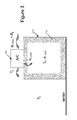
- FIG 3 illustrates the thermal power exchange that takes place in a building 110 that maintains its indoor temperature at To on a day when the external air temperature is also To and there is no appreciable sunlight.
- people and equipment in the building 110 are the principal producers of heat at the rate q LOAD .
- the air conditioner 100 removes this heat from air at temperature To and dumps it into exterior air at the same temperature. Power consumed, P B , is relatively small because the thermal load is small and thermal efficiency is good.
- Figure 4 shows the same building 110 as that of Figure 3 .
- the building is exposed to sunlight.
- the radiant power flow resulting from the sun striking the exterior of the building 110 is q SUN .
- the building 110 has a dark exterior and non-reflective windows, so all of q SUN is absorbed. Part of this thermal power conducts through the wall 115 as heat flow q1.
- the rest radiates from the exterior of the building 110 as infrared flux q IR_OUT , which is partly absorbed by terrain or objects near the building.
- the terrain or objects re-radiate some of that absorbed heat toward the building 110 as infrared flux q IR_IN .
- a fraction of the infrared flux is absorbed and conducted through the wall 115 as heat flow q2.
- T RES T 0 + ⁇ ⁇ T A
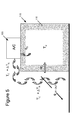
- Figure 6 illustrates the thermal radiant power exchange that takes place in building 110 if the outside of the building is highly reflective (specular or diffuse), as opposed to the dark scenarios above.
- the thermal power of the sun striking the exterior of the building 110 is q SUN .
- the building 110 may have a light exterior and reflective-coated windows, so most of q SUN is reflected. Nonetheless, part of q SUN is absorbed as thermal power that conducts through the wall as heat flow q4.
- the rest reflects from the exterior as light flux q SUN_OUT , which is partly absorbed by terrain or objects near the building. The terrain or objects re-radiate some of that absorbed heat toward the building as infrared flux q IR_IN .
- a fraction of the infrared flux is absorbed and conducted through the wall as heat flow q5.
- some of the visible light in q SUN_OUT is reflected by terrain rather than absorbed, and some of that reflected light is absorbed by the building. This is included in q IR_IN and q5.
- Figure 8 shows a structure and method in which a covering 120 may be used to 1) keep an enclosure, such as the building 110, cool, 2) reduce the capacity needed for the air conditioner 100, and 3) reduce the reservoir temperature imposed on the air conditioner.
- the covering 120 is configured to inhibit electromagnetic beams at visible light wavelengths from the sun from reaching at least a portion of the surface 123 of the building 110.
- the covering 120 is configured to retroreflect visible light beams (e.g., electromagnetic radiation having wavelengths in a range between about 380 nm and about 780 nm, or a sub-range of such wavelengths) received along beam entry paths from the sun along beam exit paths that return the visible light beams in a direction toward the sun.
- visible light beams e.g., electromagnetic radiation having wavelengths in a range between about 380 nm and about 780 nm, or a sub-range of such wavelengths
- the beam entry paths and the beam exit paths have substantially the same elevation angle with respect to the position of the sun along the horizon.
- the covering 120 may exhibit this characteristic with respect to multiple horizontal positions of the sun during throughout the day to prevent the sun from heating the building 110 and nearby terrain.
- the covering 120 may be configured so that the beam entry paths and the beam exit paths also have the same azimuthal angle. Again, the covering 120 may exhibit this characteristic with respect to multiple azimuthal positions of the sun throughout the day. In this latter instance, the covering 120 directs substantially all of the received visible light beams directly back to the sun at both the vertical and azimuthal position of the sun in the sky.
- a visible light beam along a beam entry path has a direction opposite to the direction of the visible light beam along a beam exit path.
- the covering 120 includes a plurality of retroreflective elements configured to retroreflect electromagnetic beams within a predetermined range of wavelengths.
- the thermal power of the visible wavelengths of the sun reaching the covering 120 is q SUN .
- Substantially all of q SUN is reflected back directly toward the sun by the covering 120 as light flux q SUN_OUT . Since the light flux q SUN_OUT is reflected back to the sky at an elevation angle above the horizon, that light flux is not reflected toward nearby terrain. Whether or not the azimuthal component of the light flux q SUN_OUT is retroreflected, the retroreflection of the elevation component of the light flux q SUN_OUT is effective to minimize heating of the building 110, particularly during late morning and afternoon hours when the sun is at a large elevation angle with respect to the horizon. These times are often the hottest portions of day.
- the peak capacity needed for the air conditioner 100 is reduced. Assuming more than one or two sunny days occur each year, these factors also reduce the average power consumed by the air conditioner 100.
- the covering 120 may be large enough and close enough to the building 110 to block sunlight from striking a substantial portion of the exterior surface 123 over the course of a hot day. This is shown in Figure 8 , where the sidewalls as well as the roof of the exterior surface 123 are shadowed with the covering 120. A cooling effect, however, may also be achieved by placing the covering 120 over only a limited portion of the surface 123. Further, in applications where the building 110 is close to neighboring buildings, the covering 120 may be applied on the roof of the building 110 to prevent a significant amount of scattered sunlight from reaching the other neighboring buildings.
- the covering 120 of Figure 8 may include a substrate, support structure, or the like that is covered, formed from, or embedded with a plurality of retroreflective elements.
- the retroreflective elements may be secured with one another without a substrate using a securement, a bonding process, or the like.
- the retroreflective elements may be constructed in a variety of different forms. However, such retroreflective elements generally have common characteristics such as:
- Figures 9 and 10 show a retroreflective element in the form of a corner cube reflector 125, a plurality of which may be used for the covering 120.
- the corner cube reflector 125 includes three mutually perpendicular reflective surfaces 130, 135, and 140.
- An arriving visible light beam enters the corner cube reflector 125 through an open face along a beam entry path shown by arrow 145.
- the visible light beam is reflected by the three surfaces 130, 135, and 140 before exiting the corner cube reflector 125 along the beam exit path shown by arrow 150.
- the visible light beam exiting along the beam exit path 150 has an elevation angle that is substantially the same as the elevation angle of the beam entry path 145 of the visible light beam.
- corner cube reflector 125 may reflect the visible light beams of the received sunlight back to the position of the sun with respect to the horizon. Further, the corner cube reflector 125 may also be configured so that the beam exit path shown at 150 is at an azimuthal angle that is substantially the same as the azimuthal angle of the beam entry path 145 of the visible light beam. This allows the corner cube reflector 125 to reflect the visible wavelengths of the received sunlight back to the azimuthal position of the sun in the sky.
- the reflection is completely anti-parallel and substantially all of the visible light beams included in the electromagnetic radiation received from the sun are returned directly toward the position of the sun in the sky.
- the corner cube reflector 125 may be designed so that it reflects visible light wavelengths principally in a range between about 380 nm and 780 nm. In the present example, wavelengths in a range centered roughly around 555 nanometers are used. These wavelengths correspond to the visible light wavelengths having the highest visible light power spectral density emitted from the sun.
- the reflective surfaces 130, 135, and 140 may be coated with a reflective material such as silver and aluminum. Silver and/or aluminum have strong absorption resonances in the visible band. However, other suitable coatings may also be employed.
- diffraction is minimized to so the reflected visible light beam exits the corner cube reflector 125 at an elevation angle that is parallel to, but in the opposite direction, of the visible light beam entering the corner cube reflector 125. Further, diffraction should be minimized so that the reflected visible light beam has an azimuthal angle parallel to, but in the opposite direction, of the azimuthal angle of the visible light beam entering the corner cube reflector 125.
- an effect called diffraction causes the collimated beam to spread into a wider beam having an angle, ⁇ diff, measured from the center of the beam to the first null.
- Diffraction by the corner cube reflector 125 is minimized so that most of the visible light beams entering the reflector 125 from the sun are returned toward the position at which the sun is in the sky. If the amount of diffraction is too large, the reflected visible light beam may spread to a degree where much of it strikes nearby terrain. In turn, visible light beams striking the terrain contribute to heating of the building 110 by re-radiation of thermal power from the heated terrain to the building 110.
- the angular width of a diffracted beam (i.e., the difference between the angle at which the visible light beam enters the retroreflective element and the angle at which it exits the retroreflective element) increases with the ratio of the wavelength ⁇ to the aperture width of each individual retroreflector element.
- This aspect of such an aperture is shown in Figure 10 in terms of the distance W R , which corresponds to the projected width of one face of the corner cube reflector 125.
- the Airy diffraction formula may be used to define the approximate lower bound of W R as: W R ⁇ 1.22 ⁇ ⁇ ⁇ max
- ⁇ may be selected so that it is in the range of visible light wavelengths.
- ⁇ may be selected so that it is in a range between about approximately 400 nm and 700 nm nanometers
- ⁇ max may be in a range between about 10° and 25°.
- Apertures smaller than this may result in excessive diffraction, causing too much of the reflected visible light beam to spread out and strike nearby terrain. Excessive diffraction is particularly problematic when the sun is near the horizon so the retroreflective beam path is, at best, only a few degrees above the terrain. Apertures at least as large as this minimum bound are desirable for the corner cube reflector 125 to inhibit such diffraction.
- any deviation from flatness of the surface causes the beam to spread to a wider beam angle, ⁇ error . If the reflected radiation spreads too widely (e.g. 10° in some cases, or as much as 25° in other cases) off-center when the sun is near the horizon at morning and evening), then much of it strikes nearby terrain and increases heating.
- ⁇ max 10°
- misalignment of the reflected light beam may result in an excessive amount of the visible light from the sunlight to strike nearby terrain when the sun, for example, is near the horizon.
- This criterion may be used as a parameter in designing the corner cube reflector 125.
- a retroreflective element can potentially reflect a wide range of undesirable radiation other than visible light.
- the retroreflective element may be configured to avoid reflecting radio waves and/or sound waves that might irritate or harm a person.
- retroreflecting electromagnetic energy from a cell phone back to a user may add to the RF radiation that the phone imparts to the person. In turn, this may cause discomfort and/or increase health risks that may be associated with the RF transmissions of the phone.
- reflecting audible sound wavelengths, such as those of a voice, back to a person may result in a strong echo with a short lag time making it difficult for a person to speak and/or hear.
- the audible sound wavelengths are generally in a range from about 17 mm to 17 meters, while undesirable radio frequency waves generally have wavelengths between about 7.5 cm and about 60 cm.
- the retroreflector elements may be dimensioned small enough to diffractively or specularly scatter electromagnetic radiation at these undesirable wavelengths, rather than retroreflect them back to an individual.
- an exemplary maximum bound may be imposed on the effective dimension of the aperture in accordance with the following equation: W R ⁇ 1.22 ⁇ rej ⁇ x W t
- ⁇ rej corresponds to the range of wavelengths for which retroreflection is to be limited
- W t generally corresponds to a width of a person
- ⁇ x corresponds to the smallest distance from the retroreflective element at which a person is likely to spend appreciable time. If the aperture W R meets this criterion by a small margin, the undesirable radiation is diffractively scattered. If the aperture W R is smaller than about 1/10 the size prescribed by equation (15), then the undesirable radiation is specularly reflected from the covering 120.
- the retroreflective elements reflect visible light at a narrow diffraction angle using an aperture at least as large as the minimum bound noted above, but may also satisfy the criterion that: W R ⁇ 1.22 ⁇ ⁇ IR ⁇ IR
- the value for ⁇ IR may be in a range between about 800 nm - 1 mm.
- a value of ⁇ IR in a range around 7 ⁇ m to 12 ⁇ m is used (roughly corresponding to the wavelength of infrared radiation emitted from terrain on a hot day, and shorter than audible acoustic wavelengths), and ⁇ IR is the minimum acceptable diffraction angle, here in a range that is greater than about 30° up to 90°.
- the retroreflective elements of the covering 120 need not be in the form of reflective cubes.
- Figure 11 shows a covering 160 that includes retroreflective elements in the form of transparent beads 165.
- the covering further includes an adhesive 170 and a panel/substrate 175 supporting a plurality of the transparent beads 165.
- the transparent beads 165 may be formed from glass, clear plastic, or other material having similar optical properties. Incoming visible light beams enter a front portion of a bead in a parallel direction, and are subject to refraction at the front surface. Such visible light beams are reflected from the back surface after refraction and depart the front surface. The departing visible light beams are substantially parallel to the elevation angle of the arriving electromagnetic beams, and may also be substantially parallel to the azimuthal angle of the arriving visible light beams.
- the index of refraction of the beads 165 should be a between about 1.8 to 2.0, or another value that is higher than the index of refraction of standard glass, which is about 1.5.
- the combined effect of the refraction and internal reflection of the transparent beads 165 is to return sunlight in a direction that is parallel to the direction at which it arrived, but in an opposite direction.
- the criteria set forth in Equations 10, 11, 15, and 16 above may be used as guidelines to determine the dimensions of the beads 165 having given optical characteristics.
- the adhesive 170 may be selected from a number of different materials. Such materials include, for example, thermoplastic as well as plastic materials.
- Thermoplastic binder systems are based on one of several core chemistries: hydrocarbons, rosin esters, or maleic modified rosin esters (MMRE).
- the thermoplastic coatings are generally homogeneous dry mixes of binder resins, plasticizers, glass beads (or other optics), pigments, and fillers.
- any suitable adhesive may be used.
- the covering 160 may be formed in a variety of different manners.
- One such manner includes coating the surface of panel 175 with adhesive 170.
- adhesive 170 is a thermoplastic
- the thermoplastic mix is heated to about 200 °C before being fed to an application apparatus.
- a fine mist of, for example, molten glass from an array of small apertures is sprayed into an inert gaseous atmosphere (e.g. argon) above the panel 175. If the gas is cool and the distance above the surface of the panel 175 is more than a few centimeters, the mist droplets cool and solidify into tiny spheres of glass before they reach the surface.
- the adhesive 170 grips the tiny spheres on its surface and the spheres solidify.
- the adhesive 170 is applied by a roller while the adhesive 170 is still soft. This presses the spheres further into the adhesive 170, increasing the adhesion.
- a plastic tape may be laid over and secured to the surface 175 using an industrial-grade rubber cement.
- the transparent beads 165 may be replaced by cat's eye retroreflector elements, such as the elements 185 shown in Figure 12 .
- the back surface 195 has a larger radius than the front surface 200.
- the back surface 195 has radius that is twice as large the radius of the front surface 200.
- the distance between the two surfaces may be the same as if a small sphere and a sphere twice as large had each been cut in half, and the flat face of the smaller sphere were glued to the center of the flat face of the larger sphere. This gives a retroreflection in the visible wavelengths of sunlight when the cat's eye retroreflector element material has an index of refraction between about 1.4 and 1.6.
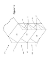
- Figures 13 and 14 show a covering in the form of a trough reflector 215 comprised of a plurality of horizontal troughs 220. All light paths shown in Figures 13 and 14 are bidirectional, i.e., visible light beams can arrive along either path and depart on the other. Consequently, each path is illustrated with an arrowhead at each end.
- the horizontal troughs 220 are arranged to reflect visible light beams along a path having the same elevation angle at which the visible light beams enter the horizontal trough 220. However, such horizontal troughs 220 may also reflect the received visible light beams at an azimuthal angle that is different from the azimuthal angle at which the visible light beams enter the horizontal trough 220. Nevertheless, returning the received visible light beams at the same elevation angle as the elevation angle at which the visible light beams are received still reduces the heating of the terrain near the building regardless of the azimuthal angle at which the visible light beams exit the horizontal trough 220.
- the horizontal troughs 220 of Figures 13 and 14 each include a set of alternating perpendicular faces.
- each horizontal trough 220 has two faces 230 and 235 of equal size.
- Each face 230 and 235 may be oriented at 45° from horizontal, one with its reflective surface upward, and the other with its reflective surface downward.
- the horizontal troughs 220 may be further oriented to let water and dust flow out of them in a manner so that faces 230 and 235 stay clean.
- the first face 230 and the second reflective faces 235 are arranged at an angle between about 84° and 96° with respect to one another.
- reflected visible light beams leave the trough reflector 220 at an elevation angle that is above the horizon.
- Reflections may be single reflections or double reflections.
- double reflections such as the reflections shown at the top of Figure 14
- visible light beams 240 leave the horizontal trough 220 as reflected light beams 245 at the same elevation angle at which the light beams 240 are received from the sun.
- single reflections such as the reflections shown in the lower portion of Figure 14
- visible light beams 250 leave the horizontal trough 220 as reflected light beams 255 at a different elevation angle than the elevation angle at which the visible light beams 250 enter from the sun.
- the elevation angle at which the reflected light beams 255 exit the horizontal trough 220 is still above the horizon.
- a plurality of the trough reflectors 220 may be bendable about their respective horizontal centerlines 217 to allow folding of the trough reflector 215, or portions thereof, for portability. Folding of the trough reflector 215 may be desirable, since the trough reflector 215 may include dozens or even hundreds of individual horizontal troughs 220 that may be folded over one another.
- Figure 15 shows a modified version of the covering shown in Figures 13 and 14 .
- the example of Figure 15 includes a reflective wall 265 disposed adjacent the plurality of horizontal troughs 220.
- a plurality of reflective walls 265 may be disposed along a length of the covering to vertically divide the horizontal troughs 220. Further, a plurality of reflective walls 265 may horizontally separate different pluralities of horizontal troughs 220.
- the azimuth angle as well as the elevation angle of the exiting visible light rays are both generally the same as, but in an opposite direction to the azimuthal angle and elevation angle the entering visible light rays when one or more reflective walls 265 are used.
- the light beam reflection path is bidirectional.
- Equations 10, 11, 15 and 16 may be used as guidelines to determine the dimensions of the troughs 220 and their relationship with each reflective wall 265.
- Another example uses a plurality of transparent fibers or prisms, each with a cross-section shaped like a circle, a cat's eye reflector, or a 90° trough behind a flat plate.
- the fibers are oriented horizontally on the covering 120.
- a vertical section view through the covering 120 with circular fibers is similar to the structure shown in Figure 11 .
- This example like the trough retro-reflectors described above, retro-reflects light to the sky with the same elevation angle at which it arrived, but typically does not reflect it along the same azimuthal angle.
- the covering 120 includes fibers
- the covering 120 includes a substrate (similar to substrate 175), a plurality of transparent fibers, and an adhesive (similar to adhesive 170) securing the plurality of transparent fibers to the substrate.
- Figures 16 and 17 show other corner cube reflectors, each having slightly different arrangement of surfaces.
- the corner cube reflectors 280 each include a plurality of pentagonal faces 285, 290, and 295 having outermost edges 300 defining a hexagonal opening. The faces slope into the page in the direction of arrows 305. Each face joins with its adjacent faces at interior angles of between about 84° to 96°.
- the corner cube reflectors 315 each include a plurality of faces 320, 325, and 330 having respective outermost edges 335 defining a triangular opening.
- the faces slope in into the page in the direction of arrows 340.
- Each face joins with its adjacent faces at interior angles of approximately 84° to 96°.
- the covering 120 may also include various modifications and/or enhancements.
- the covering 120 may be shrouded with a transparent sheet 350 that protects it from dust and renders it easier to clean compared to complex reflective surfaces alone.
- the sheet 350 may be transparent to visible light wavelengths but reflective to thermal infrared wavelengths. This latter characteristic facilitates specular reflection of infrared heat, while concurrently reducing the constraints on aperture size.
- the covering 120 may be manufactured as part of sheet 350, e.g., by molding retroreflective elements into the side sheet 350 that faces toward building 110.
- the foregoing covering 120 may also be used and/or manufactured in different manners.
- the covering 120 may be provided in a form that comprises a set of panels that are individually attached to the building 110.
- the covering 120 may be provided in the form of roof panels, siding, or other form typically used to construct a building.
- a variety of methods can be used to manufacture the panels, e.g., stamping sheet metal into the desired shape, hot-pressing sheets of aluminized plastic, or using plastic injection molding to make the structure and then depositing a reflective coating on it.
- the covering 120 may be applied on its roof to ensure that scattered sunlight does not strike on other neighboring buildings.
- the enclosure may include buildings such as houses, office buildings, grain silos, hangars, or warehouses; vehicles such as airplanes, trucks, trains, cars, boats, or ships; tanks of gas or liquid such as water, natural gas, or petroleum; or pipelines.
- buildings such as houses, office buildings, grain silos, hangars, or warehouses
- vehicles such as airplanes, trucks, trains, cars, boats, or ships
- tanks of gas or liquid such as water, natural gas, or petroleum
- pipelines are likewise within the scope of the present embodiments.
Landscapes
- Physics & Mathematics (AREA)
- General Physics & Mathematics (AREA)
- Optics & Photonics (AREA)
- Engineering & Computer Science (AREA)
- Architecture (AREA)
- Acoustics & Sound (AREA)
- Electromagnetism (AREA)
- Civil Engineering (AREA)
- Structural Engineering (AREA)
- Optical Elements Other Than Lenses (AREA)
- Building Environments (AREA)
Applications Claiming Priority (1)
| Application Number | Priority Date | Filing Date | Title |
|---|---|---|---|
| US13/900,143 US9482795B2 (en) | 2013-05-22 | 2013-05-22 | Method and system for retroreflective cooling |
Publications (1)
| Publication Number | Publication Date |
|---|---|
| EP2806076A1 true EP2806076A1 (de) | 2014-11-26 |
Family
ID=50897335
Family Applications (1)
| Application Number | Title | Priority Date | Filing Date |
|---|---|---|---|
| EP20140161459 Withdrawn EP2806076A1 (de) | 2013-05-22 | 2014-03-25 | Verfahren und System für retroreflektierende Kühlung |
Country Status (3)
| Country | Link |
|---|---|
| US (1) | US9482795B2 (de) |
| EP (1) | EP2806076A1 (de) |
| CA (1) | CA2845905C (de) |
Families Citing this family (10)
| Publication number | Priority date | Publication date | Assignee | Title |
|---|---|---|---|---|
| US9423538B2 (en) | 2013-05-22 | 2016-08-23 | The Boeing Company | Retroreflective heater |
| US9320201B2 (en) | 2013-12-20 | 2016-04-26 | Elwha Llc | Reflective articles and methods for increasing photosynthesis |
| US9499948B2 (en) | 2014-09-03 | 2016-11-22 | Flint Trading, Inc. | High content polyamide hot-applied thermoplastic composition |
| US10925268B1 (en) * | 2015-03-13 | 2021-02-23 | Ray D. Flasco | Inside corner cubic surface reflector fishing lure |
| EP3355088B1 (de) * | 2015-09-25 | 2021-09-01 | Asukanet Company, Ltd. | Retroreflektor |
| JP6949460B2 (ja) * | 2016-04-07 | 2021-10-13 | デクセリアルズ株式会社 | 光学体、窓材及びロールカーテン |
| WO2019005760A1 (en) | 2017-06-26 | 2019-01-03 | Ennis Paint, Inc. | THERMOPLASTIC COMPOSITION FOR SEALING ROOF JOINTS |
| US11630298B2 (en) * | 2017-11-15 | 2023-04-18 | Todd F. Rady | Prime polygon reflectors and methods of use |
| US12366688B2 (en) * | 2017-11-15 | 2025-07-22 | Todd Francis Rady | Prime polygon reflectors and methods of use |
| US12638625B1 (en) * | 2021-05-13 | 2026-05-26 | Vergence Automation, Inc. | Radiative heating and cooling using asymmetric infrared reflective articles |
Citations (5)
| Publication number | Priority date | Publication date | Assignee | Title |
|---|---|---|---|---|
| US4303144A (en) * | 1979-12-21 | 1981-12-01 | Lockheed Corporation | Apparatus for the retroreflection of sound |
| JP2006317648A (ja) * | 2005-05-12 | 2006-11-24 | Nikon Corp | 地球温暖化防止部材 |
| JP2011221105A (ja) * | 2010-04-05 | 2011-11-04 | Kenichi Kita | 太陽光反射材およびそれを設置した建造物 |
| US20120300306A1 (en) * | 2010-02-08 | 2012-11-29 | Sony Corporation | Optical body, method of manufacturing the same, window member, fitting, and solar shading device |
| JP2012242509A (ja) * | 2011-05-17 | 2012-12-10 | Nikon Corp | 再帰反射部材、再帰反射性建材および建築物の建築方法 |
Family Cites Families (9)
| Publication number | Priority date | Publication date | Assignee | Title |
|---|---|---|---|---|
| US3220871A (en) | 1953-06-11 | 1965-11-30 | Jerome H Lemelson | Partially metal coated transparent textile element |
| US3741623A (en) * | 1970-08-14 | 1973-06-26 | Reflex Corp Canada Ltd | Combined lens and reflector |
| US4082414A (en) | 1976-03-03 | 1978-04-04 | Pyreflex Corporation | Heat recuperation |
| NL8800294A (nl) | 1988-02-08 | 1989-09-01 | Tno | Toepassing van een retro-reflecterend scherm. |
| CN101946191A (zh) * | 2007-12-21 | 2011-01-12 | 3M创新有限公司 | 衣服、纤维和细丝形式的回射制品 |
| US8375933B2 (en) | 2008-01-23 | 2013-02-19 | Blaine E. Myers | System and method for heat energy conservation via corner reflectors |
| JP5586300B2 (ja) * | 2010-03-31 | 2014-09-10 | デクセリアルズ株式会社 | 機能性積層体及び機能性構造体 |
| JP2012003026A (ja) | 2010-06-16 | 2012-01-05 | Sony Corp | 光学体、窓材、建具および日射遮蔽装置 |
| US9423538B2 (en) | 2013-05-22 | 2016-08-23 | The Boeing Company | Retroreflective heater |
-
2013
- 2013-05-22 US US13/900,143 patent/US9482795B2/en active Active
-
2014
- 2014-03-11 CA CA2845905A patent/CA2845905C/en active Active
- 2014-03-25 EP EP20140161459 patent/EP2806076A1/de not_active Withdrawn
Patent Citations (5)
| Publication number | Priority date | Publication date | Assignee | Title |
|---|---|---|---|---|
| US4303144A (en) * | 1979-12-21 | 1981-12-01 | Lockheed Corporation | Apparatus for the retroreflection of sound |
| JP2006317648A (ja) * | 2005-05-12 | 2006-11-24 | Nikon Corp | 地球温暖化防止部材 |
| US20120300306A1 (en) * | 2010-02-08 | 2012-11-29 | Sony Corporation | Optical body, method of manufacturing the same, window member, fitting, and solar shading device |
| JP2011221105A (ja) * | 2010-04-05 | 2011-11-04 | Kenichi Kita | 太陽光反射材およびそれを設置した建造物 |
| JP2012242509A (ja) * | 2011-05-17 | 2012-12-10 | Nikon Corp | 再帰反射部材、再帰反射性建材および建築物の建築方法 |
Also Published As
| Publication number | Publication date |
|---|---|
| US20140347731A1 (en) | 2014-11-27 |
| US9482795B2 (en) | 2016-11-01 |
| CA2845905C (en) | 2018-11-27 |
| CA2845905A1 (en) | 2014-11-22 |
Similar Documents
| Publication | Publication Date | Title |
|---|---|---|
| US9482795B2 (en) | Method and system for retroreflective cooling | |
| US12061056B2 (en) | Radiative cooling with solar spectrum reflection | |
| US20250132722A1 (en) | Photovoltaic system for low solar elevation angles | |
| US8863462B2 (en) | Structure with surface for seasonal selectiveness of solar irradiation absorption and reflection | |
| JP7667818B2 (ja) | ガラス建材 | |
| US20240271768A1 (en) | Electromagnetic radiation collecting and directing device | |
| MX2014005465A (es) | Calentador retrorreflectante. | |
| EP3837479B1 (de) | Strahlführung für einen strahlungskühler | |
| US20240178789A1 (en) | Prismatic solar concentrator | |
| JP4828290B2 (ja) | 太陽光反射構造、及び、その構造を用いる設備 | |
| US9027305B2 (en) | Structure with surface for seasonal selectiveness of solar irradiation absorption and reflection | |
| AU2009101383A4 (en) | Solar energy reflection plate for suppressing global warming | |
| JP2011221105A (ja) | 太陽光反射材およびそれを設置した建造物 | |
| JP2012002892A (ja) | 窓用透明体及びその製造方法 | |
| JP5521219B2 (ja) | ルーバー装置 | |
| Greve et al. | Calculation of Solar Illumination | |
| Nishioka et al. | Numerical study on specular solar reflectors aimed at increasing solar reflectivity of building envelope | |
| Shields | PV Systems: Low Levels of Glare and Reflectance vs. Surrounding Environment |
Legal Events
| Date | Code | Title | Description |
|---|---|---|---|
| PUAI | Public reference made under article 153(3) epc to a published international application that has entered the european phase |
Free format text: ORIGINAL CODE: 0009012 |
|
| 17P | Request for examination filed |
Effective date: 20140325 |
|
| AK | Designated contracting states |
Kind code of ref document: A1 Designated state(s): AL AT BE BG CH CY CZ DE DK EE ES FI FR GB GR HR HU IE IS IT LI LT LU LV MC MK MT NL NO PL PT RO RS SE SI SK SM TR |
|
| AX | Request for extension of the european patent |
Extension state: BA ME |
|
| 17Q | First examination report despatched |
Effective date: 20150717 |
|
| STAA | Information on the status of an ep patent application or granted ep patent |
Free format text: STATUS: THE APPLICATION IS DEEMED TO BE WITHDRAWN |
|
| 18D | Application deemed to be withdrawn |
Effective date: 20160830 |