EP2806052B1 - Vorrichtung zur Elektrogewinnung von seltenem Metall mit geriffelter Zelle und Verfahren dafür - Google Patents
Vorrichtung zur Elektrogewinnung von seltenem Metall mit geriffelter Zelle und Verfahren dafür Download PDFInfo
- Publication number
- EP2806052B1 EP2806052B1 EP14150528.9A EP14150528A EP2806052B1 EP 2806052 B1 EP2806052 B1 EP 2806052B1 EP 14150528 A EP14150528 A EP 14150528A EP 2806052 B1 EP2806052 B1 EP 2806052B1
- Authority
- EP
- European Patent Office
- Prior art keywords
- electrowinning
- channel
- ion
- cell
- cathode
- Prior art date
- Legal status (The legal status is an assumption and is not a legal conclusion. Google has not performed a legal analysis and makes no representation as to the accuracy of the status listed.)
- Not-in-force
Links
Images






Classifications
-
- C—CHEMISTRY; METALLURGY
- C25—ELECTROLYTIC OR ELECTROPHORETIC PROCESSES; APPARATUS THEREFOR
- C25C—PROCESSES FOR THE ELECTROLYTIC PRODUCTION, RECOVERY OR REFINING OF METALS; APPARATUS THEREFOR
- C25C1/00—Electrolytic production, recovery or refining of metals by electrolysis of solutions
- C25C1/12—Electrolytic production, recovery or refining of metals by electrolysis of solutions of copper
-
- C—CHEMISTRY; METALLURGY
- C25—ELECTROLYTIC OR ELECTROPHORETIC PROCESSES; APPARATUS THEREFOR
- C25C—PROCESSES FOR THE ELECTROLYTIC PRODUCTION, RECOVERY OR REFINING OF METALS; APPARATUS THEREFOR
- C25C1/00—Electrolytic production, recovery or refining of metals by electrolysis of solutions
- C25C1/20—Electrolytic production, recovery or refining of metals by electrolysis of solutions of noble metals
-
- C—CHEMISTRY; METALLURGY
- C25—ELECTROLYTIC OR ELECTROPHORETIC PROCESSES; APPARATUS THEREFOR
- C25C—PROCESSES FOR THE ELECTROLYTIC PRODUCTION, RECOVERY OR REFINING OF METALS; APPARATUS THEREFOR
- C25C7/00—Constructional parts, or assemblies thereof, of cells; Servicing or operating of cells
-
- C—CHEMISTRY; METALLURGY
- C25—ELECTROLYTIC OR ELECTROPHORETIC PROCESSES; APPARATUS THEREFOR
- C25C—PROCESSES FOR THE ELECTROLYTIC PRODUCTION, RECOVERY OR REFINING OF METALS; APPARATUS THEREFOR
- C25C7/00—Constructional parts, or assemblies thereof, of cells; Servicing or operating of cells
- C25C7/02—Electrodes; Connections thereof
-
- C—CHEMISTRY; METALLURGY
- C25—ELECTROLYTIC OR ELECTROPHORETIC PROCESSES; APPARATUS THEREFOR
- C25C—PROCESSES FOR THE ELECTROLYTIC PRODUCTION, RECOVERY OR REFINING OF METALS; APPARATUS THEREFOR
- C25C7/00—Constructional parts, or assemblies thereof, of cells; Servicing or operating of cells
- C25C7/04—Diaphragms; Spacing elements
Definitions
- the present invention relates to a device for electrowinning metal and a method thereof. More particularly, the present invention relates to a device for rapidly electrowinning metal, such as Cu, Ag, Au or Pt, which is very thinly dissolved in a liquid by using a channeled cell and a method thereof.
- the rare metals refer to metallic elements which are in very danger of early exhaustion and are unstable even in supply, have scarcity so that the reserve is not sufficient and omnipresence so that they are preponderant on specific areas.
- the rare metal has been used as a generic term referring to 35 kinds of elements such as Li, a rare earth element and In.
- the rare metals refer to metallic elements which have features of scarcity due to a tiny amount of deposits and localization because the rare metals are exclusively concentrated on specific regions, so the rare metals are subject to the danger of early exhaustion and are unstable even in supply.
- the rare metal becomes a generic term to refer to 35 kinds of elements such as Li, a rare earth element and In.
- the rare earth element which is a generic term to refer to total 17 elements of scandium (Sc), yttrium (Y) and fifteen lanthanides, has been used as a core material in phosphor (TV, phosphor lamp), an abrasive (semiconductor, display) or a permanent magnet (electric vehicle, wind turbine).
- the rare earth elements could not be refined into the pure elements until the 1990's, so that they are rarely utilized.
- the technique of separating the rare earth elements has been developed, the utilization of the rare earth elements is abruptly increased from 1950.
- schemes of separating and extracting a rare earth element include fractional crystallization, fractional precipitation, selective oxidation-reduction, ion exchange, solvent extraction, and extraction chromatography.
- the europium is an element used for CRTs and three-wavelength fluorescent lamps as an activator of red phosphor in the form of high-purity oxide so that the demand of the europium has been increased.
- the content of the europium contained in a rare earth element mineral is less than 0.5% based on all rare earth elements.
- a process having several stages is required for high-purifying the europium.
- the intermediate concentrate containing 8 ⁇ 13% of europium has been obtained through a precipitation or ion exchange resin scheme.
- the concentrate containing 75% of europium has been produced through solvent extraction.
- the europium property, in which Eu 3+ can be easily reduced into Eu 2+ is utilized.
- the Eu 2+ loses a property of trivalent rare earth element ion and represents a property of alkaline earth metal ion. Based on the above property difference, the europium may be easily separated from the rare earth elements.
- the metallic reduction and electrowinning have been used to reduce Eu 3+ .
- the description of the metallic reduction will be omitted and the electrowinning of europium will be described.
- Hg-cathode electrowinning will be described with reference to FIG. 11 in which an Hg-cathode electrowinning device is depicted.
- the Hg-cathode electrowinning which is used first to refine europium through the electrowinning, uses Hg as a cathode and Pt as an anode in two electrolytic baths connected to each other through a salt bridge.
- the europium concentrate containing SO 4 2- ions is put in a cathode bath and sulfuric acid solution having the concentration of 1 mol/L is put in an anode bath. Then, if electrolyzed, EuSO 4 precipitate is formed by the europium in the cathode bath.
- the Hg-cathode electrowinning can process only a small quantity and cause bad purity of europium, and in addition, may cause mercury contamination when europium oxide is produced, so the Hg-cathode electrowinning is not industrially used in recent years.
- FIG. 12 schematically shows an ion-exchange membrane electrowinning device.
- the ion-exchange membrane electrowinning scheme which had been developed in 1980's, uses porous carbon electrodes installed in an electrolytic bath divided by an ion-exchange membrane.
- europium is electrowinning while FeCl 2 solution is being input to the cathode bath at a predetermined speed in the state that concentrated europium (RECl 2 , specifically, Eu 3+ ) solution is put in the cathode bath.
- RECl 2 specifically, Eu 3+
- the primarily reduced solution is secondarily reduced in an electrolytic bath having the same structure as that of the primary reduction, so that the europium reduction rate is increased to 99% or more. Then, the Eu 2+ solution is transferred into a precipitation device.
- the Eu 2+ solution transferred from the electrolytic bath reacts with the mixing solution of ammonium sulfate of 2 mol/L and sulfuric acid of 1 mol/L to obtain EuSO 4 precipitate. Then, the europium is separated from the EuSO 4 precipitate. In this case, to restrain europium oxidation due to air contact, the EuSO 4 precipitate is preferably purged with nitrogen gas.
- porous carbon electrode electrowinning will be described with reference to FIG. 13 which schematically shows a porous carbon electrode electrowinning device.
- reference numerals 1 and 3 denote outlets
- reference numeral 2 denotes a gas exhaustion hole
- reference number 4 denotes an inlet
- reference number 5 denotes a glass reaction container
- reference numeral 6 denotes a cathode
- reference numeral 7 denotes an anode
- reference numeral 8 denotes porous graphite.
- the porous carbon electrode electrowinning using the porous carbon electrode electrowinning device depicted in FIG. 13 uses a porous carbon electrode
- the porous carbon electrode has holes smaller than those of the ion-exchange membrane electrolytic electrode. In this case, the porosity is about 43%.
- the porous carbon electrode electrowinning utilizes the principle that, when the solution containing europium-concentrated rare earth chloride and Br is input to the material inlet under a pressure, the europium reduction reaction occurs while the solution passes through the air gaps of the cathode and the oxidation reaction of Br occurs at the anode.
- the porous carbon electrode electrowinning also has a low reduction rate so that the recovery rate is deteriorated.
- the product is contaminated by Br.
- US 5,989,407 A discloses an ozone generation and delivery system that lends itself to small scale applications and requires very low maintenance.
- the system includes an anode reservoir and a cathode phase separator each having a hydrophobic membrane to allow phase separation of produced gases from water.
- WO 96/41038 A1 discloses an electrochemical cell for removing halides from a gas mixture comprising: a first cell housing and a second cell housing; a cathode associated with said first cell housing; an anode associated with said second cell housing; a porous ceramic membrane between said first cell housing and said second cell housing; and an electrolyte within said porous ceramic membrane which is molten at a temperature above about 150°C.
- GB 2 372 626 A discloses a flow field plate for a fuel cell comprising at least one channel extending from a source of fluid to a drain for said fluid, in which the cross-sectional area of said channel at drain or source is less than 95% of the cross-sectional area at source or drain respectively.
- EP 1 262 577 A1 discloses a kit of modular components for the manufacture of an electrochemical reactor of the so-called filter-press type.
- GB 2 380 853 A discloses a fuel cell or electrolyser module, comprising: a) an electrically insulating housing comprising manifolds for operating fluids; b) a plurality of electrically conductive plates mounted in the housing with openings communicating to appropriate manifolds; and c) means to make operative sealing contact with an adjacent like module.
- the fuel cell may be of the proton exchange membrane type.
- an object of the present invention is to provide a device which is capable of greatly increasing a reaction quantity by increasing the contact area of an electrowinning solution, and at the same time, reducing the reaction time by increasing the reaction speed, without using a stirring unit or rotating an electrolytic bath, without using a porous electrode and without performing a process of electrowinning several times, and a method thereof.
- another object of the present invention is to provide an electrowinning device capable of recovering a metal, such as Cu, Ag, Au or Pt, by metalizing a metallic ion of the metal included in a low-concentrated electrowinning solution, and a method thereof.
- a metal such as Cu, Ag, Au or Pt
- Still another object of the present invention is to solve a problem of contaminating a target metal which occurs in the related art.
- a device for electrowinning metal using a channeled cell comprises a cathode cell including a channel formed on a substrate having an inlet and an outlet; an anode cell including a channel formed on a substrate having an inlet and an outlet; and an ion-exchange membrane tightly interposed between the cathode and anode cells, wherein at least one bead for generating turbulent flow is formed on inner surfaces of the channels formed in the cathode and anode cells.
- the cathode and anode cells are formed of graphite.
- the channels formed in the cathode and anode cells match with each other at both sides of the ion-exchange membrane.
- a sectional shape of the channel may be one of a rectangular shape, a U-shape, and a V-shape.
- an electrowinning solution input to the inlet may flow at Reynolds number of 2000 or more.
- a solution containing Cu, Ag, Au or Pt ion is input to the inlet formed in the cathode cell, and an ion containing solution, which pair-reacts with the solution containing Cu, Ag, Au or Pt ion, is input to the inlet formed in the anode cell.
- the pair reaction represents a reaction that may cause the most suitable reaction of precipitating Cu, Ag, Au or Pt from the solution of containing Cu, Ag, Au or Pt ion.
- the at least one bead for generating turbulent flow is installed per a unit length of the channel.
- a method of electrowinning metal using a channeled cell includes preparing a substrate for a cathode cell and a substrate for an anode cell; forming channels in the substrates; fixing the substrates having the channels to both sides of an ion-exchange membrane by tightly attaching the substrates to the both sides of the ion-exchange membrane; and electrowinning the metal after inputting an electrowinning solution through an inlet formed in the substrate, wherein at least one bead for generating turbulent flow is formed on an inner surface of the channel formed in the cathode and anode cells.
- the substrates are formed of graphite.
- an electrowinning solution input to the inlet flows at Reynolds number of 2000 or more.
- a reaction quantity of electrolytic reduction and a reaction speed may be greatly increased by using a simple constructed device, without using a stirring unit or rotating an electrolytic bath, and without using a porous electrode or performing an electrowinning process several times.
- FIG. 1 is a schematic perspective view showing a channeled cell constituting a device for electrowinning metal according to an embodiment of the present invention.
- a channeled cell 100 constituting a device for electrowinning metal may include a substrate 120, a channel 160 including an inlet 130 through which an electrowinning solution is input and an outlet 140 through which an electrowinning completed solution is discharged, and a turbulent flow generating bead 180 formed at a part of the channel 160.
- FIG. 1 although only one channeled cell 100 constituting a cathode or anode of the device for electrowinning europium is depicted in FIG. 1 , it should be understood that two channeled cells 100 are required for the cathode and anode. This will be described below with reference to FIG. 4 .
- the channel 160 of the channeled cell 100 may have an arc shape, if required, the channel 160 may have a shape formed by alternating a U-shape and an inverted-U shape. That is, the channel 160 may include a bent portion having a curved shape.
- the channel 160 depicted in FIG. 1 has the by-effect that the fluidity of the electrowinning solution, that is, the Reynolds number is increased at the portion bent at a right angle, it is preferable to allow the channel 160 to have the arc shape.
- the channeled cell 100 or the substrate 120 is formed of graphite.
- the reason of forming the channeled cell 100 or the substrate 120 of graphite is because the graphite is not corroded by acid, does not react with the europium obtained through the electrowinning, has excellent workability, and is a low price material.
- the device for electrowinning europium it is preferable in the device for electrowinning europium to form the channeled cell 100 and the substrate 120 in the same shape.
- the channeled cell 100 and the substrate 120 are preferably arranged to be matched with each other.
- At least one turbulent flow generating bead 180 is preferably formed in the channel 160 provided on the substrate 120 per a unit length.
- the unit length will be described below with reference to FIG. 2 . Further, the preferable turbulent flow generating bead 180 will be described with reference to FIG. 3 .
- FIG. 2 is a plan view showing a channeled cell constituting a device for electrowinning europium according to an embodiment of the present invention.
- the channeled cell 200 constituting the device for electrowinning europium depicted in FIG. 2 substantially has the same configuration as that depicted in FIG. 1 .
- the same elements will be assigned with the same reference numerals, and the repetition in the description of the same elements having the same reference numerals will be omitted in order to avoid redundancy.
- the turbulent flow generating bead 180 is formed at a central portion of the channeled cell 200 with respect to a horizontal width.
- the unit length represents the length from left to right of each channel 160 shown in FIG. 2 .
- the channel 160 may be formed from left to right in a single unit 160, the channel 160 may be formed in two columns separated from each other in the channel cell 200 like a double-arc shape.
- the unit length of the channel 160 having the arc shape may be equal to '1/2'.
- the unit length is a substituted unit length.
- At least one turbulent flow generating bead 180 when at least one turbulent flow generating bead 180 is formed every the unit length in a case of the arc shape, at least one turbulent flow generating bead 180 may be formed every the unit length in a case of the double-arc shape.
- the number of turbulent flow generating beads 180 having the double arc shape is compared with that of turbulent flow generating beads 180 having the arc shape, the number of turbulent flow generating beads 180 having the double-arc shape may be two times more than the number of turbulent flow generating beads 180 having the arc shape.
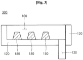
- FIG. 3 is a schematic sectional view showing a channeled cell constituting a device for electrowinning europium according to an embodiment of the present invention.
- a sectional shape of the turbulent flow generating bead 180 formed on the inner surface of the channel 160 may be known from FIG. 3 .
- the turbulent flow generating bead 180 substantially has a cross-sectional surface of a trapezoid shape, but the sectional shape of the turbulent flow generating bead 180 is not limited thereto.
- the turbulent flow generating bead 180 may have a cross-section surface of a hexagonal pillar, a water drop shape or a semicircular shape.
- the turbulent flow generating bead 180 protrudes from the inner surface of the channel 160 at a suitable height.
- the turbulent flow generating bead 180 may be formed by allowing the inner surface of the channel 160 to be concaved.
- the bead 180 may be formed on the inner surface of the channel 160 in a concave-convex shape.
- the bead 180 may be alternately formed on the inner surface of the channel 160
- the bead 180 may have any shapes if the bead 180 can cause turbulent flow on the inner surface of the channel 160.
- the turbulent flow generating bead 180 may protrude from the inner surface of the channel 160.
- a height of the turbulent flow generating bead 180 may have preferably a half of the height of the channel 160, or more preferably, two thirds of the height of the channel 160.
- the height of the bead 180 is preferably determined in accordance with the above description.
- a width or length of the turbulent flow generating bead 180 may be equal to that of the channel 160.
- the width of the turbulent flow generating bead 180 that is, the width, which is widened to the left and right in a direction of the unit length based on the width, is not limited to the width of the channel 160, but even when the width of the turbulent flow generating bead 180 is not smaller than that of the channel 160, if the by-effect of turbulent flow generation, that is, stirring is obtained, the turbulent flow generating bead 180 may have any widths.
- the inlet 130 is depicted at a low end of FIG. 3 .
- the reason is because it is assumed that the electrowinning solution is input from the rear surface of the substrate 120 when an ion-exchange membrane 420 (see FIG. 4 ) is finally interposed in the substrate 120.
- the shape of the inlet 130 may be changed into another suitable shape.
- Three turbulent flow generating beads 180 are depicted in FIG. 3 . As described above, this means that three turbulent flow generating beads 180 are formed per the unit length of the channel.
- the turbulent flow generating bead 180 formed at one place in the channel 160 having the unit length has the arc shape as shown in FIG. 2 .
- the turbulent flow generating beads 180 are formed at three places per the unit length of the channel.
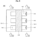
- FIG. 4 is a schematic sectional view showing a device for electrowinning europium according to an embodiment of the present invention.
- right and left substrates 120-1 and 120-2 are tightly coupled to each other in the device 400 for electrowinning europium according to an embodiment of the present invention in the state that the ion exchange membrane 420 is interposed between the right and left substrates 120-1 and 120-2.
- the right and left substrates 120-1 and 120-2 serve as a cathode cell and an anode cell.
- the cathode cell may be referred to as a cathode or a substrate and the anode cell may be referred to as an anode or a substrate.
- the anode cell may be referred to as an anode or a substrate.
- the right and left substrates 120-1 and 120-2 which serves as the anode and cathode cells, are formed of graphite.
- the cross-sectional shape of the channel 160 is rectangular.
- the sectional shape of the channel 160 may not be limited to the rectangular shape.
- the right and left substrates 120-1 and 120-2 have the same shape as described above.
- All of the channels 160 formed in the right and left substrates 120-1 and 120-2 are arranged to match with each other.
- the matched arrangement of both channels 160 means that the openings of both channels 160, which are formed in the right and left substrates 120-1 and 120-2 and face each other about the ion-exchange membrane 420, match with each other.
- the right and left substrates 120-1 and 120-2 are arranged such that the openings of the channels 160 of one side are matched with the openings of the channels 160 of the opposite side.
- the arrow a of FIG. 4 which is depicted to describe one example of the rare metal electrowinning according to the present invention, represents that a solution containing Cu 2+ is input into the cathode cell as an electrowinning solution.
- the input of the electrowinning solution is preferably performed through the inlet 130 of FIG. 1 .
- the Cu 2+- containing solution is input in the direction of arrow (a)
- a Fe 2+ -containing solution which can cause a pair reaction
- the pair reaction represents the most suitable reaction that can precipitate Cu from the Cu 2+ -containing solution.
- the Fe 2+ containing solution is used for the pair reaction.
- the Fe 2+ -containing solution makes the pair reaction with the Cu 2+ -containing solution.
- the Fe 2+ -containing solution is oxidized into the Eu 3+ containing solution.
- an electron (e - ) generated from the left substrate 120-2 flows into the right substrate 120-1 electrically connected thereto through a current flow (not shown), so that Cu is precipitated from the Cu 2+ in the electrowinning, solution input in the direction of arrow a.
- the Cu 2+ When the input solution containing Cu 2+ flows through the channel 160 in the cathode cell, the Cu 2+ obtains an electron, so that the Cu is precipitated, as denoted as the reference numeral 440 in the drawings.
- Cu precipitations 440 are depicted in the drawings as the precipitations 440 are formed on a right side wall of the channel 160, it should be noted that the precipitations 440 are formed on all of the three surfaces of the channel 160. The detailed mechanism of simultaneously forming the precipitations 440 on all of the three surfaces of the channel 160 will be described with reference to FIG. 5 .
- the reason that the precipitations 440 are produced from all of the three surfaces of the channel 160 is because the electrowinning solution flows at Reynolds number of 2000 or more so that a turbulent flow is generated.
- the Cu 2+ -containing solution as the electrowinning solution flows in the direction perpendicular to the ground, that is, in the y-axis direction perpendicular to the ground when it is assumed that the ground is an x-axis.
- the Cu 3+ -drained solution remaining after being precipitated into Cu may be discharged through the outlet 140 denoted as arrow b in FIG. 4
- the sulfuric acid (H 2 SO 4 ) dissociates into SO 4 2- ions, so that the precipitation of Cu 2+ into Cu is accelerated by the SO 4 2- ions.
- FIG. 5 is a view showing a simulation of a fluid flow difference according to Reynolds number in a channel of a device for electrowinning metal according to an embodiment of the present invention, where (a) is a view showing a case that the Reynolds number is 69.44 and (b) is a view showing a case that the Reynolds number is 6944.
- FIG. 5 is a view showing the case that the Reynolds number of 69.44 and the flow rate of 10cc/hr
- (b) of FIG. 5 is a view showing the case of the Reynolds number of 6944 and the flow rate of 1000 cc/hr.
- FIG. 5 are views showing the mass-transfer phenomenon according to each of the Reynolds (Re) numbers as velocity vectors colored according to velocity magnitudes when the electrowinning solution is provided into the channel 160.
- the Reynolds number is a term of the hydrodynamic field that is defined as the ratio of "an inertia force” to "a viscous force".
- the Re number is defined as the simple formula of (liquid density * flow velocity * vertical height)/liquid viscosity.
- the Re number is utilized as one of the most important non-dimensional numbers in hydrodynamics and specifically, hydrokinetics. It has been know that, when the Re numbers are similar with each other, two types of fluid flows represent flows that are similar to each other in hydrodynamics.
- the Re number is 2000 or more, it may be expected that since a flowing material, for example, an electrowinning solution makes contact with the electrode surface, and in more detail, makes contact with x and y axes, the probability that the flowing material makes contact with the electrode surface is increased, so that the reaction efficiency is proportionally increased.
- a flowing material for example, an electrowinning solution makes contact with the electrode surface, and in more detail, makes contact with x and y axes
- the Re number is less than 2000, it may be expected that although the flowing material, for example, an electrowinning solution makes contact with the electrode surface, the probability that the flowing material makes contact with the electrode surface is decreased, so that the reaction efficiency is proportionally decreased.
- the Cu 2+ -containing solution has been controlled to have the Cu concentration of 1000ppm and the H 2 SO 4 concentration of 0.01 -2 M.
- the cross sectional areas of the channel have been set into 0.2, cm 2 and the total length of the channel has been fixed at 200 cm.
- the theoretical quantity of electric charge required for electrowinning Cu by reducing Cu 2+ ions to 100% may be calculated according to Faraday law. It has been set in the present invention to apply 90%, 100%, 150% and 200 % of the theoretical quantity of electric charge.
- FIG. 6 is a graph showing variations of Reynolds number and a recovery rate in a device for electrowinning metal according to an embodiment of the present invention.
- the recovery rate (%) exceeds about 60% at the Re number less than 2,000, that is, about the Re number of 1,500. However, it is known that the recovery rate (%) reaches at 95% at the Re number of 2,000 or more so that the recovery rate actually approaches to 100%.
- the Re number reaches at 3,000, there is no difference in the recovery rate.
- the Re number of at least 2,000 according to an embodiment of the present invention is preferable.
- FIG. 7 is a graph showing a quantity of electric charge (which is a value substituted into applied quantity of electric charge/theoretical quantity of electric charge) and a recovery rate in a device for electrowinning metal according to an embodiment of the present invention.
- the recovery rate (%) is equal to or less than 95%.
- the recovery rates (%) are 95% or more in all cases.
- the quantity of supplied electric charge is over 110%, the quantity of electric charge has no correlation with the recovery rate (%).
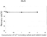
- FIG. 8 is a graph showing variations of sulfuric acid concentration of a solution containing Cu 2+ and a recovery rate in a device for electrowinning metal according to an embodiment of the present invention.
- the sulfuric acid concentration preferably is '1' M. It is preferably determined that the limit of the sulfuric acid concentration is '2' M.
- FIG. 9 is a graph showing a variation of a recovery rate according to a type of a metal electrowinned through a device for electrowinning metal according to an embodiment of the present invention.
- the electrowinning device according to the embodiment is enabled to be applied for electrowinning various rare metal as well as Cu.
- FIG. 10 is a flowchart schematically illustrating a method of electrowinning metal according to an embodiment of the present invention.
- a method of electrowinning metal includes a step S10 of preparing substrates, a step S20 of forming channels in the substrates, a step S30 of attaching the substrates to both side surfaces of an ion-exchange membrane, and a step S40 of performing electrowinning after inputting an electrowinning solution.
- the substrates 120 which are formed of graphite are prepared.
- the channels 160 having a particular shape are formed in the substrates 120-1 and 120-2.
- the substrate 120-1 and 120-2 for a cathode and an anode are attached to both side surfaces of the ion exchange membrane 420 (see FIG. 4 ).
- the ion exchange membrane 420 may be a negative-ion exchange membrane or to the contrary, a positive-ion exchange membrane according to the electric property of the solution input to the substrate 120-1 or 120-2.
- the negative-ion exchange membrane has been used as the ion exchange membrane 420 because a Cu 2+ -containing solution has been used as the electrowinning solution.
- the ion exchange membrane 420 must be the positive-ion exchange membrane.
- the Cu 2+ -containing solution is input through the inlet 130 and then, the electrowinning is performed.
- the Cu 2+ -containing solution flows at the Re number of 2,000 by the turbulent flow generating bead 180 formed in the substrate 120-1, so that the Cu is reduced in on the three surfaces of the channel 160, so that the Cu is precipitated as the Cu precipitations 440.
- the Re number of 2,000 or more is achieved by inputting the Cu 2+ -containing solution into the inlet 130 at a high rate, it should be noted that the Re number of 2,000 or more may be achieved through the turbulent flow generating bead 180.
- the Cu precipitations 440 precipitated and attached to the three surfaces of the substrate 120-1 can be easily separated from the substrate 120-1 after the substrate 120-1 has been removed from the ion exchange membrane 420 ( FIG. 4 ) .
Landscapes
- Chemical & Material Sciences (AREA)
- Engineering & Computer Science (AREA)
- Chemical Kinetics & Catalysis (AREA)
- Electrochemistry (AREA)
- Materials Engineering (AREA)
- Metallurgy (AREA)
- Organic Chemistry (AREA)
- Electrolytic Production Of Metals (AREA)
- Manufacture And Refinement Of Metals (AREA)
Claims (10)
- Vorrichtung zur Elektrogewinnung von Metall mit einer mit einem Kanal versehenen Zelle (100, 200, 300, 400), wobei die Vorrichtung umfasst:eine Kathodenzelle, die einen auf einem Substrat (120) ausgebildeten Kanal (160) mit einem Einlass (130) und einem Auslass (140) aufweist;eine Anodenzelle, die einen auf einem Substrat (120) ausgebildeten Kanal (160) mit einem Einlass (130) und einem Auslass (140) aufweist;eine lonenaustauschmembran (420), die dicht zwischen der Kathoden- und der Anodenzelle angeordnet ist,dadurch gekennzeichnet, dass wenigstens eine Wulst (180) zum Erzeugen einer turbulenten Strömung auf Innenflächen der Kanäle (160) ausgebildet ist, die in der Kathoden- und der Anodenzelle ausgebildet sind.
- Vorrichtung nach Anspruch 1, wobei die Kathoden- und die Anodenzelle aus Graphit ausgebildet sind.
- Vorrichtung nach Anspruch 1, wobei
die Kanäle (160), die in der Kathoden- und der Anodenzelle ausgebildet sind, an beiden Seiten der Ionenaustauschmembran (420) miteinander übereinstimmen. - Vorrichtung nach Anspruch 1, wobei
eine Querschnittsform des Kanals (160) eine rechteckige Form, eine U-Form und/oder eine V-Form ist. - Vorrichtung nach Anspruch 1, wobei
eine Elektrogewinnungslösung, die in den Einlass (130) eingespeist wird, mit einer Reynolds-Zahl von 2000 oder mehr strömt. - Vorrichtung nach Anspruch 5, wobei
die Elektrogewinnungslösung, die Cu-, Ag-, Au- oder Pt-Ionen enthält, in den Einlass (130) eingespeist wird, der in der Kathodenzelle ausgebildet ist, und
eine ionenhaltige Lösung, welche mit der Elektrogewinnungslösung, die Cu-, Ag-, Au- oder Pt-Ionen enthält, eine Paar-Reaktion eingeht, in den Einlass (130) eingespeist wird, der in der Anodenzelle ausgebildet ist. - Vorrichtung nach Anspruch 1, wobei
die wenigstens eine Wulst (180) zum Erzeugen einer turbulenten Strömung jeweils einmal pro Einheitslängenabschnitt des Kanals (160) angebracht ist. - Verfahren zur Elektrogewinnung von Metall mit einer mit einem Kanal versehenen Zelle (100, 200, 300, 400), wobei das Verfahren durch die folgenden Schritte gekennzeichnet ist:Herstellen eines Substrats (120) für eine Kathodenzelle und eines Substrats (120) für eine Anodenzelle;Ausbilden von Kanälen (160) in den Substraten (120);Befestigen der Substrate (120), welche die Kanäle (160) aufweisen, auf beiden Seiten einer Ionenaustauschmembran (420), indem die Substrate (120) dicht an den beiden Seiten der Ionenaustauschmembran (420) angebracht werden; undDurchführen einer Elektrogewinnung des Metalls nach dem Einspeisen einer Elektrogewinnungslösung durch einen Einlass (130), der in dem Substrat (120) ausgebildet ist,wobei wenigstens eine Wulst (180) zum Erzeugen einer turbulenten Strömung auf einer Innenfläche des Kanals (160) ausgebildet ist, der in dem Substrat (120) ausgebildet ist.
- Verfahren nach Anspruch 8, wobei die Substrate (120) aus Graphit ausgebildet sind.
- Verfahren nach Anspruch 8, wobei eine Elektrogewinnungslösung, die in den Einlass (130) eingespeist wird, mit einer Reynolds-Zahl von 2000 oder mehr strömt.
Applications Claiming Priority (1)
| Application Number | Priority Date | Filing Date | Title |
|---|---|---|---|
| KR1020130058935A KR101349305B1 (ko) | 2013-05-24 | 2013-05-24 | 유로형 셀을 이용한 희유 금속의 전해 채취 장치, 및 그 방법 |
Publications (2)
| Publication Number | Publication Date |
|---|---|
| EP2806052A1 EP2806052A1 (de) | 2014-11-26 |
| EP2806052B1 true EP2806052B1 (de) | 2016-12-14 |
Family
ID=49920178
Family Applications (1)
| Application Number | Title | Priority Date | Filing Date |
|---|---|---|---|
| EP14150528.9A Not-in-force EP2806052B1 (de) | 2013-05-24 | 2014-01-09 | Vorrichtung zur Elektrogewinnung von seltenem Metall mit geriffelter Zelle und Verfahren dafür |
Country Status (3)
| Country | Link |
|---|---|
| EP (1) | EP2806052B1 (de) |
| JP (1) | JP5871338B2 (de) |
| KR (1) | KR101349305B1 (de) |
Families Citing this family (1)
| Publication number | Priority date | Publication date | Assignee | Title |
|---|---|---|---|---|
| CN109666952B (zh) * | 2017-10-16 | 2020-12-04 | 中国科学院过程工程研究所 | 一种电沉积生产金属银的方法 |
Family Cites Families (16)
| Publication number | Priority date | Publication date | Assignee | Title |
|---|---|---|---|---|
| FR2033327B1 (de) * | 1969-02-12 | 1974-03-01 | Eastman Kodak Co | |
| US4707239A (en) * | 1986-03-11 | 1987-11-17 | The United States Of America As Represented By The Secretary Of The Interior | Electrode assembly for molten metal production from molten electrolytes |
| DE4243697C1 (de) * | 1992-12-18 | 1994-03-17 | Mib Metallurg Und Oberflaechen | Elektrolytisches Verfahren zur Gewinnung von Platin hoher Reinheit aus Platinlegierungen |
| JP2786408B2 (ja) * | 1995-06-06 | 1998-08-13 | 壽化工機株式会社 | 電解酸性水製造装置 |
| US5618405A (en) * | 1995-06-07 | 1997-04-08 | Georgia Tech Research Corporation | Removal and recovery of hydrogen halides using an electrochemical membrane |
| JP2911393B2 (ja) | 1995-07-25 | 1999-06-23 | 日本テクノ株式会社 | 無電解ニッケルめっき廃液から肥料水溶液を製造する方法と装置 |
| US5989407A (en) * | 1997-03-31 | 1999-11-23 | Lynntech, Inc. | Generation and delivery device for ozone gas and ozone dissolved in water |
| US5837122A (en) * | 1997-04-21 | 1998-11-17 | The Scientific Ecology Group, Inc. | Electrowinning electrode, cell and process |
| DE19841302C2 (de) * | 1998-09-10 | 2002-12-19 | Inst Mikrotechnik Mainz Gmbh | Reaktor sowie Verfahren zur Durchführung elektrochemischer Umsetzungen |
| GB2372626B (en) * | 2001-05-03 | 2003-02-12 | Morgan Crucible Co | Flow field plate geometries |
| ATE260350T1 (de) * | 2001-05-24 | 2004-03-15 | Casale Chemicals Sa | Elektrochemischer reaktor |
| WO2003034530A2 (en) * | 2001-10-11 | 2003-04-24 | The Morgan Crucible Company Plc | Fuel cell or electrolyser construction |
| WO2004079051A1 (en) * | 2003-03-04 | 2004-09-16 | FRS WATERWATER, INC. (d.b.a. WATERWARE, INC.) | High electric field electrolysis cell |
| KR101011141B1 (ko) * | 2003-08-12 | 2011-01-26 | 한라공조주식회사 | 적층형 히터코어용 플레이트 |
| MX2010013510A (es) * | 2010-12-09 | 2012-06-08 | Univ Autonoma Metropolitana | Electrorecuperacion de oro y plata a partir de soluciones de tiosulfato. |
| WO2013054341A2 (en) * | 2011-07-08 | 2013-04-18 | Ganapati Dadasaheb Yadav | Effect of operating parameters on the performance of electrochemical cell in copper-chlorine cycle |
-
2013
- 2013-05-24 KR KR1020130058935A patent/KR101349305B1/ko active Active
-
2014
- 2014-01-09 EP EP14150528.9A patent/EP2806052B1/de not_active Not-in-force
- 2014-01-13 JP JP2014003838A patent/JP5871338B2/ja not_active Expired - Fee Related
Also Published As
| Publication number | Publication date |
|---|---|
| EP2806052A1 (de) | 2014-11-26 |
| JP5871338B2 (ja) | 2016-03-01 |
| KR101349305B1 (ko) | 2014-01-13 |
| JP2014227603A (ja) | 2014-12-08 |
Similar Documents
| Publication | Publication Date | Title |
|---|---|---|
| KR102274666B1 (ko) | 중수의 전해농축 방법 | |
| CN201390683Y (zh) | 一种用于处理含氰废水的多级电解装置 | |
| CN101886271B (zh) | 一种用于旋流电解方法的装置 | |
| US6287448B1 (en) | Electrochemical production of lithium using a lithium amalgam anode | |
| CN111875124B (zh) | 一种三氟化氮制备过程中产生的含镍废渣废水的处理方法 | |
| AU2015252689B2 (en) | Insertable electrode device that does not generate acid mist or other gases, and method | |
| Hirai et al. | Separation of europium from samarium and gadolinium by combination of electrochemical reduction and solvent extraction | |
| CN102453929A (zh) | 密闭式电积槽 | |
| EP2806052A1 (de) | Vorrichtung zur Elektrogewinnung von seltenem Metall mit geriffelter Zelle und Verfahren dafür | |
| US20030057104A1 (en) | Electrolytic process for the production of metallic copper and apparatus therefor | |
| US20140353164A1 (en) | Device for electrowinning europium with channeled cell and method thereof | |
| CN114337373A (zh) | 流动流体电化学方法 | |
| CN109763136B (zh) | 一种不用脱气的酸碱发生装置 | |
| US20230203678A1 (en) | Salt-splitting electrolysis system comprising flow electrodes and methods of operating such systems | |
| CN105177636B (zh) | 一种电积装置及电积的方法 | |
| JP7207024B2 (ja) | 硫酸溶液の製造方法 | |
| CN109666952A (zh) | 一种电沉积生产金属银的方法 | |
| CN202499779U (zh) | 含镍清洗水处理设备 | |
| CN222574806U (zh) | 一种制备三氟化氮的电解槽 | |
| US20230296291A1 (en) | Heat Generation Method and Device Using Ionic Vacancies Generated by Electrochemical Reaction | |
| CN106702434B (zh) | 电解装置及电解方法 | |
| CN108977831A (zh) | 一种连续电化学溶解钌粉的方法 | |
| CN108977836B (zh) | 一种连续电化学溶解铱粉的方法 | |
| JP3340273B2 (ja) | 複合電極及びそれを用いる三フッ化窒素ガスの製造方法 | |
| JPH03153891A (ja) | 第四アンモニウム水酸化物の電解製造装置 |
Legal Events
| Date | Code | Title | Description |
|---|---|---|---|
| PUAI | Public reference made under article 153(3) epc to a published international application that has entered the european phase |
Free format text: ORIGINAL CODE: 0009012 |
|
| 17P | Request for examination filed |
Effective date: 20140109 |
|
| AK | Designated contracting states |
Kind code of ref document: A1 Designated state(s): AL AT BE BG CH CY CZ DE DK EE ES FI FR GB GR HR HU IE IS IT LI LT LU LV MC MK MT NL NO PL PT RO RS SE SI SK SM TR |
|
| AX | Request for extension of the european patent |
Extension state: BA ME |
|
| RIN1 | Information on inventor provided before grant (corrected) |
Inventor name: LEE, JIN-YOUNG Inventor name: CHUNG, KYEONG-WOO Inventor name: KIM, SUNG-DON |
|
| R17P | Request for examination filed (corrected) |
Effective date: 20150526 |
|
| RBV | Designated contracting states (corrected) |
Designated state(s): AL AT BE BG CH CY CZ DE DK EE ES FI FR GB GR HR HU IE IS IT LI LT LU LV MC MK MT NL NO PL PT RO RS SE SI SK SM TR |
|
| RIC1 | Information provided on ipc code assigned before grant |
Ipc: C25C 1/12 20060101AFI20160428BHEP Ipc: C25C 1/20 20060101ALI20160428BHEP Ipc: C25C 7/00 20060101ALI20160428BHEP |
|
| GRAP | Despatch of communication of intention to grant a patent |
Free format text: ORIGINAL CODE: EPIDOSNIGR1 |
|
| INTG | Intention to grant announced |
Effective date: 20160624 |
|
| GRAS | Grant fee paid |
Free format text: ORIGINAL CODE: EPIDOSNIGR3 |
|
| GRAA | (expected) grant |
Free format text: ORIGINAL CODE: 0009210 |
|
| AK | Designated contracting states |
Kind code of ref document: B1 Designated state(s): AL AT BE BG CH CY CZ DE DK EE ES FI FR GB GR HR HU IE IS IT LI LT LU LV MC MK MT NL NO PL PT RO RS SE SI SK SM TR |
|
| REG | Reference to a national code |
Ref country code: GB Ref legal event code: FG4D |
|
| REG | Reference to a national code |
Ref country code: CH Ref legal event code: EP |
|
| REG | Reference to a national code |
Ref country code: IE Ref legal event code: FG4D |
|
| REG | Reference to a national code |
Ref country code: AT Ref legal event code: REF Ref document number: 853662 Country of ref document: AT Kind code of ref document: T Effective date: 20170115 |
|
| REG | Reference to a national code |
Ref country code: DE Ref legal event code: R096 Ref document number: 602014005396 Country of ref document: DE |
|
| PG25 | Lapsed in a contracting state [announced via postgrant information from national office to epo] |
Ref country code: LV Free format text: LAPSE BECAUSE OF FAILURE TO SUBMIT A TRANSLATION OF THE DESCRIPTION OR TO PAY THE FEE WITHIN THE PRESCRIBED TIME-LIMIT Effective date: 20161214 |
|
| REG | Reference to a national code |
Ref country code: LT Ref legal event code: MG4D |
|
| REG | Reference to a national code |
Ref country code: NL Ref legal event code: MP Effective date: 20161214 |
|
| PG25 | Lapsed in a contracting state [announced via postgrant information from national office to epo] |
Ref country code: LT Free format text: LAPSE BECAUSE OF FAILURE TO SUBMIT A TRANSLATION OF THE DESCRIPTION OR TO PAY THE FEE WITHIN THE PRESCRIBED TIME-LIMIT Effective date: 20161214 Ref country code: GR Free format text: LAPSE BECAUSE OF FAILURE TO SUBMIT A TRANSLATION OF THE DESCRIPTION OR TO PAY THE FEE WITHIN THE PRESCRIBED TIME-LIMIT Effective date: 20170315 Ref country code: SE Free format text: LAPSE BECAUSE OF FAILURE TO SUBMIT A TRANSLATION OF THE DESCRIPTION OR TO PAY THE FEE WITHIN THE PRESCRIBED TIME-LIMIT Effective date: 20161214 Ref country code: NO Free format text: LAPSE BECAUSE OF FAILURE TO SUBMIT A TRANSLATION OF THE DESCRIPTION OR TO PAY THE FEE WITHIN THE PRESCRIBED TIME-LIMIT Effective date: 20170314 |
|
| REG | Reference to a national code |
Ref country code: AT Ref legal event code: MK05 Ref document number: 853662 Country of ref document: AT Kind code of ref document: T Effective date: 20161214 |
|
| PG25 | Lapsed in a contracting state [announced via postgrant information from national office to epo] |
Ref country code: FI Free format text: LAPSE BECAUSE OF FAILURE TO SUBMIT A TRANSLATION OF THE DESCRIPTION OR TO PAY THE FEE WITHIN THE PRESCRIBED TIME-LIMIT Effective date: 20161214 Ref country code: HR Free format text: LAPSE BECAUSE OF FAILURE TO SUBMIT A TRANSLATION OF THE DESCRIPTION OR TO PAY THE FEE WITHIN THE PRESCRIBED TIME-LIMIT Effective date: 20161214 Ref country code: RS Free format text: LAPSE BECAUSE OF FAILURE TO SUBMIT A TRANSLATION OF THE DESCRIPTION OR TO PAY THE FEE WITHIN THE PRESCRIBED TIME-LIMIT Effective date: 20161214 |
|
| PG25 | Lapsed in a contracting state [announced via postgrant information from national office to epo] |
Ref country code: NL Free format text: LAPSE BECAUSE OF FAILURE TO SUBMIT A TRANSLATION OF THE DESCRIPTION OR TO PAY THE FEE WITHIN THE PRESCRIBED TIME-LIMIT Effective date: 20161214 |
|
| PG25 | Lapsed in a contracting state [announced via postgrant information from national office to epo] |
Ref country code: CZ Free format text: LAPSE BECAUSE OF FAILURE TO SUBMIT A TRANSLATION OF THE DESCRIPTION OR TO PAY THE FEE WITHIN THE PRESCRIBED TIME-LIMIT Effective date: 20161214 Ref country code: EE Free format text: LAPSE BECAUSE OF FAILURE TO SUBMIT A TRANSLATION OF THE DESCRIPTION OR TO PAY THE FEE WITHIN THE PRESCRIBED TIME-LIMIT Effective date: 20161214 Ref country code: SK Free format text: LAPSE BECAUSE OF FAILURE TO SUBMIT A TRANSLATION OF THE DESCRIPTION OR TO PAY THE FEE WITHIN THE PRESCRIBED TIME-LIMIT Effective date: 20161214 Ref country code: IS Free format text: LAPSE BECAUSE OF FAILURE TO SUBMIT A TRANSLATION OF THE DESCRIPTION OR TO PAY THE FEE WITHIN THE PRESCRIBED TIME-LIMIT Effective date: 20170414 Ref country code: RO Free format text: LAPSE BECAUSE OF FAILURE TO SUBMIT A TRANSLATION OF THE DESCRIPTION OR TO PAY THE FEE WITHIN THE PRESCRIBED TIME-LIMIT Effective date: 20161214 |
|
| PG25 | Lapsed in a contracting state [announced via postgrant information from national office to epo] |
Ref country code: PT Free format text: LAPSE BECAUSE OF FAILURE TO SUBMIT A TRANSLATION OF THE DESCRIPTION OR TO PAY THE FEE WITHIN THE PRESCRIBED TIME-LIMIT Effective date: 20170414 Ref country code: PL Free format text: LAPSE BECAUSE OF FAILURE TO SUBMIT A TRANSLATION OF THE DESCRIPTION OR TO PAY THE FEE WITHIN THE PRESCRIBED TIME-LIMIT Effective date: 20161214 Ref country code: BG Free format text: LAPSE BECAUSE OF FAILURE TO SUBMIT A TRANSLATION OF THE DESCRIPTION OR TO PAY THE FEE WITHIN THE PRESCRIBED TIME-LIMIT Effective date: 20170314 Ref country code: SM Free format text: LAPSE BECAUSE OF FAILURE TO SUBMIT A TRANSLATION OF THE DESCRIPTION OR TO PAY THE FEE WITHIN THE PRESCRIBED TIME-LIMIT Effective date: 20161214 Ref country code: AT Free format text: LAPSE BECAUSE OF FAILURE TO SUBMIT A TRANSLATION OF THE DESCRIPTION OR TO PAY THE FEE WITHIN THE PRESCRIBED TIME-LIMIT Effective date: 20161214 Ref country code: IT Free format text: LAPSE BECAUSE OF FAILURE TO SUBMIT A TRANSLATION OF THE DESCRIPTION OR TO PAY THE FEE WITHIN THE PRESCRIBED TIME-LIMIT Effective date: 20161214 Ref country code: ES Free format text: LAPSE BECAUSE OF FAILURE TO SUBMIT A TRANSLATION OF THE DESCRIPTION OR TO PAY THE FEE WITHIN THE PRESCRIBED TIME-LIMIT Effective date: 20161214 |
|
| REG | Reference to a national code |
Ref country code: CH Ref legal event code: PL |
|
| REG | Reference to a national code |
Ref country code: DE Ref legal event code: R097 Ref document number: 602014005396 Country of ref document: DE |
|
| PG25 | Lapsed in a contracting state [announced via postgrant information from national office to epo] |
Ref country code: MC Free format text: LAPSE BECAUSE OF FAILURE TO SUBMIT A TRANSLATION OF THE DESCRIPTION OR TO PAY THE FEE WITHIN THE PRESCRIBED TIME-LIMIT Effective date: 20161214 |
|
| PLBE | No opposition filed within time limit |
Free format text: ORIGINAL CODE: 0009261 |
|
| STAA | Information on the status of an ep patent application or granted ep patent |
Free format text: STATUS: NO OPPOSITION FILED WITHIN TIME LIMIT |
|
| REG | Reference to a national code |
Ref country code: FR Ref legal event code: ST Effective date: 20170929 |
|
| PG25 | Lapsed in a contracting state [announced via postgrant information from national office to epo] |
Ref country code: FR Free format text: LAPSE BECAUSE OF NON-PAYMENT OF DUE FEES Effective date: 20170214 Ref country code: CH Free format text: LAPSE BECAUSE OF NON-PAYMENT OF DUE FEES Effective date: 20170131 Ref country code: LI Free format text: LAPSE BECAUSE OF NON-PAYMENT OF DUE FEES Effective date: 20170131 |
|
| REG | Reference to a national code |
Ref country code: IE Ref legal event code: MM4A |
|
| 26N | No opposition filed |
Effective date: 20170915 |
|
| PG25 | Lapsed in a contracting state [announced via postgrant information from national office to epo] |
Ref country code: DK Free format text: LAPSE BECAUSE OF FAILURE TO SUBMIT A TRANSLATION OF THE DESCRIPTION OR TO PAY THE FEE WITHIN THE PRESCRIBED TIME-LIMIT Effective date: 20161214 Ref country code: LU Free format text: LAPSE BECAUSE OF NON-PAYMENT OF DUE FEES Effective date: 20170109 |
|
| PG25 | Lapsed in a contracting state [announced via postgrant information from national office to epo] |
Ref country code: SI Free format text: LAPSE BECAUSE OF FAILURE TO SUBMIT A TRANSLATION OF THE DESCRIPTION OR TO PAY THE FEE WITHIN THE PRESCRIBED TIME-LIMIT Effective date: 20161214 Ref country code: IE Free format text: LAPSE BECAUSE OF NON-PAYMENT OF DUE FEES Effective date: 20170109 |
|
| GBPC | Gb: european patent ceased through non-payment of renewal fee |
Effective date: 20180109 |
|
| PG25 | Lapsed in a contracting state [announced via postgrant information from national office to epo] |
Ref country code: MT Free format text: LAPSE BECAUSE OF NON-PAYMENT OF DUE FEES Effective date: 20170109 |
|
| PG25 | Lapsed in a contracting state [announced via postgrant information from national office to epo] |
Ref country code: GB Free format text: LAPSE BECAUSE OF NON-PAYMENT OF DUE FEES Effective date: 20180109 |
|
| PG25 | Lapsed in a contracting state [announced via postgrant information from national office to epo] |
Ref country code: HU Free format text: LAPSE BECAUSE OF FAILURE TO SUBMIT A TRANSLATION OF THE DESCRIPTION OR TO PAY THE FEE WITHIN THE PRESCRIBED TIME-LIMIT; INVALID AB INITIO Effective date: 20140109 |
|
| PG25 | Lapsed in a contracting state [announced via postgrant information from national office to epo] |
Ref country code: CY Free format text: LAPSE BECAUSE OF FAILURE TO SUBMIT A TRANSLATION OF THE DESCRIPTION OR TO PAY THE FEE WITHIN THE PRESCRIBED TIME-LIMIT Effective date: 20161214 |
|
| PG25 | Lapsed in a contracting state [announced via postgrant information from national office to epo] |
Ref country code: MK Free format text: LAPSE BECAUSE OF FAILURE TO SUBMIT A TRANSLATION OF THE DESCRIPTION OR TO PAY THE FEE WITHIN THE PRESCRIBED TIME-LIMIT Effective date: 20161214 |
|
| PG25 | Lapsed in a contracting state [announced via postgrant information from national office to epo] |
Ref country code: TR Free format text: LAPSE BECAUSE OF FAILURE TO SUBMIT A TRANSLATION OF THE DESCRIPTION OR TO PAY THE FEE WITHIN THE PRESCRIBED TIME-LIMIT Effective date: 20161214 |
|
| PG25 | Lapsed in a contracting state [announced via postgrant information from national office to epo] |
Ref country code: AL Free format text: LAPSE BECAUSE OF FAILURE TO SUBMIT A TRANSLATION OF THE DESCRIPTION OR TO PAY THE FEE WITHIN THE PRESCRIBED TIME-LIMIT Effective date: 20161214 |
|
| PGFP | Annual fee paid to national office [announced via postgrant information from national office to epo] |
Ref country code: DE Payment date: 20240119 Year of fee payment: 11 |
|
| PGFP | Annual fee paid to national office [announced via postgrant information from national office to epo] |
Ref country code: BE Payment date: 20240119 Year of fee payment: 11 |
|
| REG | Reference to a national code |
Ref country code: DE Ref legal event code: R119 Ref document number: 602014005396 Country of ref document: DE |
|
| PG25 | Lapsed in a contracting state [announced via postgrant information from national office to epo] |
Ref country code: DE Free format text: LAPSE BECAUSE OF NON-PAYMENT OF DUE FEES Effective date: 20250801 |
|
| PG25 | Lapsed in a contracting state [announced via postgrant information from national office to epo] |
Ref country code: BE Free format text: LAPSE BECAUSE OF NON-PAYMENT OF DUE FEES Effective date: 20250131 |
|
| REG | Reference to a national code |
Ref country code: BE Ref legal event code: MM Effective date: 20250131 |