EP2806040A1 - A martensitic alloy component and process of forming a martensitic alloy component - Google Patents
A martensitic alloy component and process of forming a martensitic alloy component Download PDFInfo
- Publication number
- EP2806040A1 EP2806040A1 EP14168707.9A EP14168707A EP2806040A1 EP 2806040 A1 EP2806040 A1 EP 2806040A1 EP 14168707 A EP14168707 A EP 14168707A EP 2806040 A1 EP2806040 A1 EP 2806040A1
- Authority
- EP
- European Patent Office
- Prior art keywords
- component
- martensitic alloy
- martensitic
- inches
- alloy component
- Prior art date
- Legal status (The legal status is an assumption and is not a legal conclusion. Google has not performed a legal analysis and makes no representation as to the accuracy of the status listed.)
- Granted
Links
Images
Classifications
-
- C—CHEMISTRY; METALLURGY
- C22—METALLURGY; FERROUS OR NON-FERROUS ALLOYS; TREATMENT OF ALLOYS OR NON-FERROUS METALS
- C22C—ALLOYS
- C22C38/00—Ferrous alloys, e.g. steel alloys
- C22C38/18—Ferrous alloys, e.g. steel alloys containing chromium
- C22C38/40—Ferrous alloys, e.g. steel alloys containing chromium with nickel
- C22C38/46—Ferrous alloys, e.g. steel alloys containing chromium with nickel with vanadium
-
- C—CHEMISTRY; METALLURGY
- C21—METALLURGY OF IRON
- C21D—MODIFYING THE PHYSICAL STRUCTURE OF FERROUS METALS; GENERAL DEVICES FOR HEAT TREATMENT OF FERROUS OR NON-FERROUS METALS OR ALLOYS; MAKING METAL MALLEABLE, e.g. BY DECARBURISATION OR TEMPERING
- C21D1/00—General methods or devices for heat treatment, e.g. annealing, hardening, quenching or tempering
- C21D1/55—Hardenability tests, e.g. end-quench tests
-
- C—CHEMISTRY; METALLURGY
- C21—METALLURGY OF IRON
- C21D—MODIFYING THE PHYSICAL STRUCTURE OF FERROUS METALS; GENERAL DEVICES FOR HEAT TREATMENT OF FERROUS OR NON-FERROUS METALS OR ALLOYS; MAKING METAL MALLEABLE, e.g. BY DECARBURISATION OR TEMPERING
- C21D8/00—Modifying the physical properties of ferrous metals or ferrous alloys by deformation combined with, or followed by, heat treatment
- C21D8/06—Modifying the physical properties of ferrous metals or ferrous alloys by deformation combined with, or followed by, heat treatment during manufacturing of rods or wires
-
- C—CHEMISTRY; METALLURGY
- C22—METALLURGY; FERROUS OR NON-FERROUS ALLOYS; TREATMENT OF ALLOYS OR NON-FERROUS METALS
- C22C—ALLOYS
- C22C38/00—Ferrous alloys, e.g. steel alloys
-
- C—CHEMISTRY; METALLURGY
- C22—METALLURGY; FERROUS OR NON-FERROUS ALLOYS; TREATMENT OF ALLOYS OR NON-FERROUS METALS
- C22C—ALLOYS
- C22C38/00—Ferrous alloys, e.g. steel alloys
- C22C38/02—Ferrous alloys, e.g. steel alloys containing silicon
-
- C—CHEMISTRY; METALLURGY
- C22—METALLURGY; FERROUS OR NON-FERROUS ALLOYS; TREATMENT OF ALLOYS OR NON-FERROUS METALS
- C22C—ALLOYS
- C22C38/00—Ferrous alloys, e.g. steel alloys
- C22C38/04—Ferrous alloys, e.g. steel alloys containing manganese
-
- C—CHEMISTRY; METALLURGY
- C22—METALLURGY; FERROUS OR NON-FERROUS ALLOYS; TREATMENT OF ALLOYS OR NON-FERROUS METALS
- C22C—ALLOYS
- C22C38/00—Ferrous alloys, e.g. steel alloys
- C22C38/18—Ferrous alloys, e.g. steel alloys containing chromium
- C22C38/40—Ferrous alloys, e.g. steel alloys containing chromium with nickel
- C22C38/42—Ferrous alloys, e.g. steel alloys containing chromium with nickel with copper
-
- C—CHEMISTRY; METALLURGY
- C22—METALLURGY; FERROUS OR NON-FERROUS ALLOYS; TREATMENT OF ALLOYS OR NON-FERROUS METALS
- C22C—ALLOYS
- C22C38/00—Ferrous alloys, e.g. steel alloys
- C22C38/18—Ferrous alloys, e.g. steel alloys containing chromium
- C22C38/40—Ferrous alloys, e.g. steel alloys containing chromium with nickel
- C22C38/44—Ferrous alloys, e.g. steel alloys containing chromium with nickel with molybdenum or tungsten
-
- Y—GENERAL TAGGING OF NEW TECHNOLOGICAL DEVELOPMENTS; GENERAL TAGGING OF CROSS-SECTIONAL TECHNOLOGIES SPANNING OVER SEVERAL SECTIONS OF THE IPC; TECHNICAL SUBJECTS COVERED BY FORMER USPC CROSS-REFERENCE ART COLLECTIONS [XRACs] AND DIGESTS
- Y02—TECHNOLOGIES OR APPLICATIONS FOR MITIGATION OR ADAPTATION AGAINST CLIMATE CHANGE
- Y02E—REDUCTION OF GREENHOUSE GAS [GHG] EMISSIONS, RELATED TO ENERGY GENERATION, TRANSMISSION OR DISTRIBUTION
- Y02E10/00—Energy generation through renewable energy sources
- Y02E10/70—Wind energy
- Y02E10/72—Wind turbines with rotation axis in wind direction
Definitions
- the present invention is directed to martensitic alloys, articles including martensitic alloys, and processes of forming alloys. More specifically, the present invention is directed to a reduced nickel-chromium martensitic alloy and a process of forming a reduced nickel-chromium martensitic alloy.
- Wind turbines are exposed to significant operational stresses from wind, rotational forces and the weight of a plurality of blades.
- the operational stresses are often amplified by environmental temperatures with extremes depending on geographical location.
- the materials used for the components of the wind turbines must be able to withstand operating stresses and strains throughout the range of temperatures.
- Wind turbines have a main shaft that transmits power from a rotor to a generator. As wind turbines increase their outputs from 1.5 and 2.5 megawatts (MW) to 3, 4, 5, and 6 MW, the size and required properties of the wind turbine drive shaft increases. In addition, the loads from gearbox components, such as planet gear carriers, are typically too high for conventional ductile iron grades (ferritic/pearlitic grades). Forged/hardened steel is the material of choice for gearbox components and drive shafts having sizes greater than 3 tons. This shaft is typically machined out of a steel forging. The material of the shaft is usually quenched-tempered high-strength low-alloy steel with critical fatigue properties. A common alloy currently used for these large wind turbine components is 34CrNiMo6 steel.
- the nickel and chromium provide a desirable hardenability of the alloy.
- 34CrNiMo6 steel provides desired hardenability and fracture appearance transition temperature (FATT)
- FATT fracture appearance transition temperature
- the nickel and chromium used in 34CrNiMo6 steel is expensive, increasing the price of wind turbines and replacement shafts.
- a desired feature for wind turbine components is a FATT of -40°C (-40°F).
- the FATT is the temperature at which the fracture surface of a material is 50% low energy brittle cleavage and 50% high energy ductile fibrous. Both a composition of the material as well as the processes for forming and heat treating the material affect FATT. FATT is important because it represents the temperature above which brittle fracture will not occur. The lower the FATT, the greater the toughness of the material.
- Martensitic stainless steels such as 34 CrNiMo6 steel, having excellent strength, low brittle to ductile transition temperature, and good hardening characteristics in thick sections have long been used as turbine shaft materials. Decreasing the amount of Ni and Cr in the alloy decreases the hardenability, which reduces the amount of martensite that forms in the material. Reducing the amount of martensite has the undesirable consequence of increasing the FATT of the material.
- a martensitic alloy and a method of forming an inexpensive martensitic alloy having reduced amounts of nickel and chromium and not suffering from the above drawbacks would be desirable in the art.
- a martensitic alloy component includes by weight:
- the component has a hardenability corresponding to an ideal diameter of greater than about 10 inches (25.4 cm).
- a process of forming a reduced nickel-chromium martensitic alloy component includes forging the reduced nickel-chromium alloy component including by weight:
- the reduced nickel-chromium martensitic alloy component is austenitized, quenched and tempered.
- the tempered forged alloy has a hardenability corresponding to an ideal diameter of greater than about 10 inches (25.4 cm).
- Embodiments of the present disclosure in comparison to methods and products not utilizing one or more features disclosed herein, decrease nickel percentage, decrease chromium percentage, increase carbon percentage, increase manganese percentage, decrease material cost, maintain or increase martensite percentage, maintain or decrease fracture appearance transition temperature (FATT), or a combination thereof.
- the disclosure includes a process for producing the main shaft for a wind turbine from a martensitic alloy, though it should be understood that the invention is also well suited for the production of a wide variety of components from martensitic alloy compositions.
- Other non-limiting examples include automotive components, such as turbine shafts, axles, and various other components used in the energy, automotive, railroad, construction, mining and agricultural industries. Such components are well known in the art and therefore require no further description.
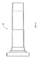
- the shaft 100 is represented as having a tubular shape with a flange formed at one end, though it can be appreciated that FIG. 1 is merely a schematic representation and different configurations for the shaft 100 are also within the scope of the invention.
- the shaft 100 shown in FIG. 1 includes a plurality of segments, the shaft 100 may also be formed of a unitary piece.
- the shaft 100 may be solid or hollow or a combination of solid and hollow components.
- the shaft 100 has an axisymmetric geometry with respect to the longitudinal axis of rotation of the shaft 100.
- the main shaft 100 will have an outer diameter well in excess of 20 inches (about 50 cm), and more typically in excess of 24 inches (about 60 cm), with a typical range being about 25 to 60 inches (about 63 to about 152 cm), though lesser and greater diameters are also foreseeable.
- Other aspects of the shaft 100, including its installation in wind turbines and the operation of the wind turbines, are otherwise known in the art, and therefore will not be discussed here in any detail.
- the martensitic alloy includes the composition shown in Table 1.
- Table 1 wt% Broad Range Alternate Range Alternate Range C 0.38-0.43 0.38-0.43 0.39-0.41 Si 0.15-.030 0.15-.030 0.20-.025 Mn 1.00-1.25 1.05-1.25 1.10-1.17 Ni 0.75-0.90 0.75-0.90 0.78-0.85 Cr 1.00-1.30 1.00-1.30 1.10-1.20 Mo 0.25-0.35 0.25-0.35 0.27-0.32 V 0.05-0.12 0.05-0.12 0.07-0.11 S ⁇ 0.015 ⁇ 0.015 ⁇ 0.015 P ⁇ 0.015 ⁇ 0.015 ⁇ 0.015 Cu ⁇ 0.15 ⁇ 0.15 ⁇ 0.15 Fe Bal Bal Bal Bal Bal Bal Bal Bal Bal Bal Bal Bal Bal Bal Bal Bal Bal Bal Bal Bal Bal Bal Bal Bal Bal Bal Bal Bal Bal Bal Bal Bal Bal Bal Bal Bal Bal Bal Bal Bal Bal Bal Bal Bal Bal Bal Bal Bal Bal Bal Bal Bal Bal Bal Bal Bal Bal Bal Bal Bal Bal Bal Bal Bal Bal Bal
- a component formed from the composition, according to the present disclosure includes a hardenability corresponding to an ideal diameter of greater than about 10 inches (25.4 cm) or 10 to 18 inches (25.4 to 45.72 cm) or 11 to 12 inches (27.94 to 30.48 cm) or 13 to 14 inches (33.02 to 35.56 cm) or any suitable combination, subcombination, range, or sub-range within.
- the component has a hardenability corresponding to an ideal diameter of about 11.4 inches (28.96 cm).
- the component has a hardenability corresponding to an ideal diameter of about 13.3 inches (33.78cm).
- Hardenability corresponding to an ideal diameter is the ability of material, component, and heat treatment (e.g., after quench from an austenitizing temperature), to form at least 50% martensite at the center of a solid cylinder. While the above definition of hardenability corresponding to an ideal diameter is based from a solid component, one of ordinary skill in the art would understand that the geometry is not limited to a solid cylinder and may include other geometries and/or hollow components. For example, the hardenability of hollow components corresponds to the corresponding center depth within the material (e.g., the center of the wall) in which at least 50% martensite forms after heat treatment.
- the martensitic microstructure has increased material toughness as compared to bainite and ferrite/pearlite microstructures. Increasing the percentage of martensite in the material microstructure will decrease the FATT of the material. Increasing the ideal diameter of a material increases the amount of martensite thus decreasing the FATT of the material in thicker cross sections. A material at a temperature below the FATT will have low fracture toughness and low damage tolerance. To form a damage tolerant component, the operating temperature of the component should be above the FATT.
- a component formed from the composition includes a FATT at the surface of less than -40°F (-40°C) or less than -50°F (-45.6°C) or less than -60°F (-51.1°C).
- the component includes a FATT of less than 86°F (30°C) or less than 80°F (26.7°C) or less than 75°F (23.9°C) at the maximum thickness of the component.
- properties of the material that decrease FATT include, but are not limited to, increasing martensite percentage, decreasing grain size, decreasing yield strength, or a combination thereof.
- a desired yield strength of the material is 650 MPa or greater or about 650 MPa to about 1000 MPa and tensile strength between about 800 and about 1,000 MPa.
- the average grain size of a material is formed during processing of the material, and is maintained to about 62 ⁇ m or less or about 50 ⁇ m or less.
- the FATT of the material having a defined yield strength range and grain size range is adjusted through adjustments in microstructure.
- the microstructure is adjusted through increases and/or decreases in concentrations of alloying elements.
- the alloying elements include, but are not limited to, carbon, silicon, manganese, nickel, chromium, molybdenum, vanadium, sulfur, phosphorus, copper, or a combination thereof. In addition to adjusting microstructure, increases and/or decreases in the concentrations of the alloying elements adjust material strength, toughness, ductility, grain size, or a combination thereof.
- the nickel concentration and the chromium concentration are decreased and a carbon concentration and a manganese concentration are increased.
- a hardenability of a material is affected by the amount of each element present in the material. The hardenability is the ease at which the material forms a martensitic structure during quenching from an austenitizing temperature. Increasing the carbon concentration and the manganese concentration maintains or increases a hardenability of the material. Increasing the hardenability of the material increases the ideal diameter, which increases martensitic structure formation and decreases the FATT in thick cross sections, thus providing for increased damage tolerance.
- An exemplary process for forming the component includes forging of the component. After forging, the component is heat treated through methods including, but not limited to, austenitizing, quenching, tempering, or a combination thereof.
- Austenitizing is the process of holding the martensitic alloy forging above a critical temperature for a sufficient period of time to ensure that the matrix is fully transformed to austenite.
- austenitizing includes holding the forging at temperatures greater than about 870°C (1598°F) for a time period that is sufficient to fully convert the matrix of the thickest section to austenite.
- Quenching from the austenitizing temperature forms a martensite microstructure and may be accomplished with any suitable quenching method known in the art.
- the rate of quench has to be high enough to reduce or eliminate ferrite/pearlite formation.
- Tempering is provided to increase the toughness and reduce the brittleness of the component. Suitable tempering temperatures include, but are not limited to, between about 550°C (1022°F) and about 650°C (1202°F), between about 580°C (1076°F) and about 620°C (1048°F), or about 600°C (1112°F), or any combination, subcombination, range, or sub-range thereof.
- Comparative Example 1 The known composition of 34CrNiMo6 steel, a material known for use in wind turbine main shaft manufacture, is shown below: Comparative Ex. 1 - 34CrNiMo6 wt% Carbon 0.34 Silicon 0.2 Manganese 0.65 Nickel 1.5 Chromium 1.5 Molybdenum 0.23 Vanadium - Iron Balance
- the nominal composition of Comparative Example 1 corresponds to a hardenability corresponding to an ideal diameter of 7.4 inches.
- Comparative Example 2 A steel alloy composition having the following composition: Comparative Ex. 2 wt% wt% Carbon 0.26 Silicon 0.23 Manganese 1.00 Nickel 0.70 Chromium 1.10 Molybdenum 0.25 Vanadium 0.09 Sulfur ⁇ 0.015 Phosphorus ⁇ 0.015 Copper ⁇ 0.25 Iron Balance
- the nominal composition of Comparative Example 2 has a hardenability corresponding to an ideal diameter of 6.1 inches.
- Example 1 A martensitic alloy composition having the following composition: Example 1 Element wt% Carbon 0.35 Silicon 0.31 Manganese 1.12 Nickel 0.94 Chromium 1.31 Molybdenum 0.35 Vanadium 0.092 Sulfur 0.002 Phosphorus 0.014 Copper 0.06 Aluminum 0.004 Tin 0.004 Antimony 0.001 Arsenic 0.003 Iron Balance
- a component, shown as Example 1, is formed from an exemplary composition according to the present disclosure.
- the final product includes a hardenability corresponding to an ideal diameter of 13.3 inches (33.78 cm).
- Example 2 A martensitic alloy composition having the following composition: Example 2 Element wt% Carbon 0.40 Silicon 0.23 Manganese 1.10 Nickel 0.80 Chromium 1.15 Molybdenum 0.30 Vanadium 0.09 Sulfur - Phosphorus - Copper - Iron Balance
- a component, shown as Example 2 is formed from an exemplary composition according to the present disclosure.
- the final product includes a hardenability corresponding to an ideal diameter of 12.4 inches (31.50 cm).
- Example 3 A martensitic alloy composition having the following omposition: Example 3 Element wt% Carbon 0.43 Silicon 0.30 Manganese 1.25 Nickel 0.90 Chromium 1.30 Molybdenum 0.35 Vanadium 0.12 Iron Balance
- a component, shown as Example 3, is formed from an exemplary composition, according to the present disclosure.
- the final product includes a hardenability corresponding to an ideal diameter of 17.3 inches (43.94 cm).
Landscapes
- Chemical & Material Sciences (AREA)
- Engineering & Computer Science (AREA)
- Materials Engineering (AREA)
- Mechanical Engineering (AREA)
- Metallurgy (AREA)
- Organic Chemistry (AREA)
- Physics & Mathematics (AREA)
- Thermal Sciences (AREA)
- Crystallography & Structural Chemistry (AREA)
- Manufacturing & Machinery (AREA)
- Heat Treatment Of Articles (AREA)
- Wind Motors (AREA)
Abstract
Description
- The present invention is directed to martensitic alloys, articles including martensitic alloys, and processes of forming alloys. More specifically, the present invention is directed to a reduced nickel-chromium martensitic alloy and a process of forming a reduced nickel-chromium martensitic alloy.
- Wind turbines are exposed to significant operational stresses from wind, rotational forces and the weight of a plurality of blades. The operational stresses are often amplified by environmental temperatures with extremes depending on geographical location. The materials used for the components of the wind turbines must be able to withstand operating stresses and strains throughout the range of temperatures.
- Wind turbines have a main shaft that transmits power from a rotor to a generator. As wind turbines increase their outputs from 1.5 and 2.5 megawatts (MW) to 3, 4, 5, and 6 MW, the size and required properties of the wind turbine drive shaft increases. In addition, the loads from gearbox components, such as planet gear carriers, are typically too high for conventional ductile iron grades (ferritic/pearlitic grades). Forged/hardened steel is the material of choice for gearbox components and drive shafts having sizes greater than 3 tons. This shaft is typically machined out of a steel forging. The material of the shaft is usually quenched-tempered high-strength low-alloy steel with critical fatigue properties. A common alloy currently used for these large wind turbine components is 34CrNiMo6 steel. The nickel and chromium provide a desirable hardenability of the alloy. Although 34CrNiMo6 steel provides desired hardenability and fracture appearance transition temperature (FATT), the nickel and chromium used in 34CrNiMo6 steel is expensive, increasing the price of wind turbines and replacement shafts.
- A desired feature for wind turbine components is a FATT of -40°C (-40°F). The FATT is the temperature at which the fracture surface of a material is 50% low energy brittle cleavage and 50% high energy ductile fibrous. Both a composition of the material as well as the processes for forming and heat treating the material affect FATT. FATT is important because it represents the temperature above which brittle fracture will not occur. The lower the FATT, the greater the toughness of the material.
- Martensitic stainless steels, such as 34 CrNiMo6 steel, having excellent strength, low brittle to ductile transition temperature, and good hardening characteristics in thick sections have long been used as turbine shaft materials. Decreasing the amount of Ni and Cr in the alloy decreases the hardenability, which reduces the amount of martensite that forms in the material. Reducing the amount of martensite has the undesirable consequence of increasing the FATT of the material.
- A martensitic alloy and a method of forming an inexpensive martensitic alloy having reduced amounts of nickel and chromium and not suffering from the above drawbacks would be desirable in the art.
- In an exemplary embodiment of the present disclosure, a martensitic alloy component includes by weight:
- about 0.38% to about 0.43% C;
- about 0.15% to about 0.30% Si;
- about 1.00% to about 1.25% Mn;
- about 0.75% to about 0.90% Ni;
- about 1.00% to about 1.30% Cr;
- about 0.25% to about 0.35% Mo;
- about 0.05% to about 0.12% V;
- up to about 0.015% S;
- up to about 0.015% P;
- up to about 0.15% Cu; and
- balance iron and incidental impurities.
- The component has a hardenability corresponding to an ideal diameter of greater than about 10 inches (25.4 cm).
- In another embodiment of the present disclosure, a process of forming a reduced nickel-chromium martensitic alloy component includes forging the reduced nickel-chromium alloy component including by weight:
- about 0.38% to about 0.43% C;
- about 0.15% to about 0.30% Si;
- about 1.00% to about 1.25% Mn;
- about 0.75% to about 0.90% Ni;
- about 1.00% to about 1.30% Cr;
- about 0.25% to about 0.35% Mo;
- about 0.05% to about 0.12% V;
- up to about 0.015% S;
- up to about 0.015% P;
- up to about 0.15% Cu; and
- balance iron and incidental impurities.
- After forging, the reduced nickel-chromium martensitic alloy component is austenitized, quenched and tempered. The tempered forged alloy has a hardenability corresponding to an ideal diameter of greater than about 10 inches (25.4 cm).
- Other features and advantages of the present invention will be apparent from the following more detailed description of the preferred embodiment, taken in conjunction with the accompanying drawings which illustrate, by way of example, the principles of the invention.
- Provided is an exemplary reduced nickel-chromium alloy component having a plurality of predetermined properties and a process of forming the reduced nickel-chromium alloy component having a plurality of predetermined properties. Embodiments of the present disclosure, in comparison to methods and products not utilizing one or more features disclosed herein, decrease nickel percentage, decrease chromium percentage, increase carbon percentage, increase manganese percentage, decrease material cost, maintain or increase martensite percentage, maintain or decrease fracture appearance transition temperature (FATT), or a combination thereof.
- In one embodiment, the disclosure includes a process for producing the main shaft for a wind turbine from a martensitic alloy, though it should be understood that the invention is also well suited for the production of a wide variety of components from martensitic alloy compositions. Other non-limiting examples include automotive components, such as turbine shafts, axles, and various other components used in the energy, automotive, railroad, construction, mining and agricultural industries. Such components are well known in the art and therefore require no further description.
- With reference to
FIG. 1 , theshaft 100 is represented as having a tubular shape with a flange formed at one end, though it can be appreciated thatFIG. 1 is merely a schematic representation and different configurations for theshaft 100 are also within the scope of the invention. Although theshaft 100 shown inFIG. 1 includes a plurality of segments, theshaft 100 may also be formed of a unitary piece. Theshaft 100 may be solid or hollow or a combination of solid and hollow components. Theshaft 100 has an axisymmetric geometry with respect to the longitudinal axis of rotation of theshaft 100. For use in the wind turbine 10, themain shaft 100 will have an outer diameter well in excess of 20 inches (about 50 cm), and more typically in excess of 24 inches (about 60 cm), with a typical range being about 25 to 60 inches (about 63 to about 152 cm), though lesser and greater diameters are also foreseeable. Other aspects of theshaft 100, including its installation in wind turbines and the operation of the wind turbines, are otherwise known in the art, and therefore will not be discussed here in any detail. - The martensitic alloy, according to the present disclosure, includes the composition shown in Table 1.
Table 1 wt% Broad Range Alternate Range Alternate Range C 0.38-0.43 0.38-0.43 0.39-0.41 Si 0.15-.030 0.15-.030 0.20-.025 Mn 1.00-1.25 1.05-1.25 1.10-1.17 Ni 0.75-0.90 0.75-0.90 0.78-0.85 Cr 1.00-1.30 1.00-1.30 1.10-1.20 Mo 0.25-0.35 0.25-0.35 0.27-0.32 V 0.05-0.12 0.05-0.12 0.07-0.11 S <0.015 <0.015 <0.015 P <0.015 <0.015 <0.015 Cu <0.15 <0.15 <0.15 Fe Bal Bal Bal - A component formed from the composition, according to the present disclosure, includes a hardenability corresponding to an ideal diameter of greater than about 10 inches (25.4 cm) or 10 to 18 inches (25.4 to 45.72 cm) or 11 to 12 inches (27.94 to 30.48 cm) or 13 to 14 inches (33.02 to 35.56 cm) or any suitable combination, subcombination, range, or sub-range within. In one embodiment, the component has a hardenability corresponding to an ideal diameter of about 11.4 inches (28.96 cm). In another embodiment, the component has a hardenability corresponding to an ideal diameter of about 13.3 inches (33.78cm). Hardenability corresponding to an ideal diameter, as utilized herein, is the ability of material, component, and heat treatment (e.g., after quench from an austenitizing temperature), to form at least 50% martensite at the center of a solid cylinder. While the above definition of hardenability corresponding to an ideal diameter is based from a solid component, one of ordinary skill in the art would understand that the geometry is not limited to a solid cylinder and may include other geometries and/or hollow components. For example, the hardenability of hollow components corresponds to the corresponding center depth within the material (e.g., the center of the wall) in which at least 50% martensite forms after heat treatment.
- The martensitic microstructure has increased material toughness as compared to bainite and ferrite/pearlite microstructures. Increasing the percentage of martensite in the material microstructure will decrease the FATT of the material. Increasing the ideal diameter of a material increases the amount of martensite thus decreasing the FATT of the material in thicker cross sections. A material at a temperature below the FATT will have low fracture toughness and low damage tolerance. To form a damage tolerant component, the operating temperature of the component should be above the FATT.
- In one embodiment, a component formed from the composition, according to the present disclosure, includes a FATT at the surface of less than -40°F (-40°C) or less than -50°F (-45.6°C) or less than -60°F (-51.1°C). In addition, the component includes a FATT of less than 86°F (30°C) or less than 80°F (26.7°C) or less than 75°F (23.9°C) at the maximum thickness of the component.
- In addition to increasing the ideal diameter, properties of the material that decrease FATT include, but are not limited to, increasing martensite percentage, decreasing grain size, decreasing yield strength, or a combination thereof. In one embodiment, a desired yield strength of the material is 650 MPa or greater or about 650 MPa to about 1000 MPa and tensile strength between about 800 and about 1,000 MPa. In a further embodiment, the average grain size of a material is formed during processing of the material, and is maintained to about 62 µm or less or about 50 µm or less. The FATT of the material having a defined yield strength range and grain size range is adjusted through adjustments in microstructure. In one embodiment, the microstructure is adjusted through increases and/or decreases in concentrations of alloying elements. The alloying elements include, but are not limited to, carbon, silicon, manganese, nickel, chromium, molybdenum, vanadium, sulfur, phosphorus, copper, or a combination thereof. In addition to adjusting microstructure, increases and/or decreases in the concentrations of the alloying elements adjust material strength, toughness, ductility, grain size, or a combination thereof.
- In one embodiment, the nickel concentration and the chromium concentration are decreased and a carbon concentration and a manganese concentration are increased. A hardenability of a material is affected by the amount of each element present in the material. The hardenability is the ease at which the material forms a martensitic structure during quenching from an austenitizing temperature. Increasing the carbon concentration and the manganese concentration maintains or increases a hardenability of the material. Increasing the hardenability of the material increases the ideal diameter, which increases martensitic structure formation and decreases the FATT in thick cross sections, thus providing for increased damage tolerance.
- An exemplary process for forming the component includes forging of the component. After forging, the component is heat treated through methods including, but not limited to, austenitizing, quenching, tempering, or a combination thereof. Austenitizing is the process of holding the martensitic alloy forging above a critical temperature for a sufficient period of time to ensure that the matrix is fully transformed to austenite. In order to produce a single phase matrix microstructure (austenite) with a uniform carbon distribution, austenitizing includes holding the forging at temperatures greater than about 870°C (1598°F) for a time period that is sufficient to fully convert the matrix of the thickest section to austenite. Quenching from the austenitizing temperature forms a martensite microstructure and may be accomplished with any suitable quenching method known in the art. The rate of quench has to be high enough to reduce or eliminate ferrite/pearlite formation. Tempering is provided to increase the toughness and reduce the brittleness of the component. Suitable tempering temperatures include, but are not limited to, between about 550°C (1022°F) and about 650°C (1202°F), between about 580°C (1076°F) and about 620°C (1048°F), or about 600°C (1112°F), or any combination, subcombination, range, or sub-range thereof.
- Comparative Example 1: The known composition of 34CrNiMo6 steel, a material known for use in wind turbine main shaft manufacture, is shown below:
Comparative Ex. 1 - 34CrNiMo6 wt% Carbon 0.34 Silicon 0.2 Manganese 0.65 Nickel 1.5 Chromium 1.5 Molybdenum 0.23 Vanadium - Iron Balance - The nominal composition of Comparative Example 1 corresponds to a hardenability corresponding to an ideal diameter of 7.4 inches.
- Comparative Example 2: A steel alloy composition having the following composition:
Comparative Ex. 2 wt% wt% Carbon 0.26 Silicon 0.23 Manganese 1.00 Nickel 0.70 Chromium 1.10 Molybdenum 0.25 Vanadium 0.09 Sulfur <0.015 Phosphorus <0.015 Copper <0.25 Iron Balance - The nominal composition of Comparative Example 2 has a hardenability corresponding to an ideal diameter of 6.1 inches.
- Example 1: A martensitic alloy composition having the following composition:
Example 1 Element wt% Carbon 0.35 Silicon 0.31 Manganese 1.12 Nickel 0.94 Chromium 1.31 Molybdenum 0.35 Vanadium 0.092 Sulfur 0.002 Phosphorus 0.014 Copper 0.06 Aluminum 0.004 Tin 0.004 Antimony 0.001 Arsenic 0.003 Iron Balance - A component, shown as Example 1, is formed from an exemplary composition according to the present disclosure. The final product includes a hardenability corresponding to an ideal diameter of 13.3 inches (33.78 cm).
- Example 2: A martensitic alloy composition having the following composition:
Example 2 Element wt% Carbon 0.40 Silicon 0.23 Manganese 1.10 Nickel 0.80 Chromium 1.15 Molybdenum 0.30 Vanadium 0.09 Sulfur - Phosphorus - Copper - Iron Balance - A component, shown as Example 2, is formed from an exemplary composition according to the present disclosure. The final product includes a hardenability corresponding to an ideal diameter of 12.4 inches (31.50 cm).
- Example 3: A martensitic alloy composition having the following omposition:
Example 3 Element wt% Carbon 0.43 Silicon 0.30 Manganese 1.25 Nickel 0.90 Chromium 1.30 Molybdenum 0.35 Vanadium 0.12 Iron Balance - A component, shown as Example 3, is formed from an exemplary composition, according to the present disclosure. The final product includes a hardenability corresponding to an ideal diameter of 17.3 inches (43.94 cm).
- While the invention has been described with reference to a preferred embodiment, it will be understood by those skilled in the art that various changes may be made and equivalents may be substituted for elements thereof without departing from the scope of the invention. In addition, many modifications may be made to adapt a particular situation or material to the teachings of the invention without departing from the essential scope thereof. Therefore, it is intended that the invention not be limited to the particular embodiment disclosed as the best mode contemplated for carrying out this invention, but that the invention will include all embodiments falling within the scope of the appended claims. The terms "includes" and "comprising" also cover the terms "consist of and "consisting of".
Claims (15)
- A martensitic alloy component, comprising by weight:about 0.38% to about 0.43% C;about 0.15% to about 0.30% Si;about 1.00% to about 1.25% Mn;about 0.75% to about 0.90% Ni;about 1.00% to about 1.30% Cr;about 0.25% to about 0.35% Mo;about 0.05% to about 0.12% V;up to about 0.015% S;up to about 0.015% P;up to about 0.15% Cu; andbalance iron and incidental impurities;wherein the component has a hardenability corresponding to an ideal diameter of greater than about 25.4 cm (10 inches).
- The martensitic alloy component of claim 1, wherein the component comprises about 1.05 to about 1.25% Mn.
- The martensitic alloy component of claim 1 or claim 2, wherein the component comprises about 1.15% Mn.
- The martensitic alloy component of any preceding claim, wherein the component has a hardenability corresponding to an ideal diameter of from about 25.4 to 45.72 cm (about 10 inches to about 18 inches).
- The martensitic alloy component of claim 4, wherein the component has a hardenability corresponding to an ideal diameter of from about 27.94 to 30.48 cm (about 11 inches to about 12 inches).
- The martensitic alloy component of claim 4, wherein the component has a hardenability corresponding to an ideal diameter of from about 33.02 to 35.56 cm (about 13 inches to about 14 inches).
- The martensitic alloy component of any preceding claim, further comprising a fracture apparent transition temperature at a surface of the component of less than-40°C.
- The martensitic alloy component of any preceding claim, further comprising a fracture apparent transition temperature at a maximum thickness of the component of less than 30 °C.
- The martensitic alloy component of any preceding claim, wherein the martensitic alloy component has a average grain size of less than about 62 µm.
- The martensitic alloy component of any preceding claim, wherein the martensitic alloy component has a yield strength at a surface of the component of greater than about 650 MPa.
- The martensitic alloy component of any preceding claim, wherein the martensitic alloy component has a tensile strength at a surface of the component of between about 800 and about 1,000 MPa.
- The martensitic alloy component of any preceding claim, wherein the component has a thickness of greater than 20 inches.
- The martensitic alloy component of any preceding claim, wherein the component is a wind turbine shaft.
- The martensitic alloy component of claim 13, wherein the wind turbine shaft has at least one solid segment and/or at least one hollow segment.
- A process of forming a martensitic alloy component, the process comprising:forging an alloy comprising by weight:about 0.38% to about 0.43% C;about 0.15% to about 0.30% Si;about 1.00% to about 1.25% Mn;about 0.75% to about 0.90% Ni;about 1.00% to about 1.30% Cr;about 0.25% to about 0.35% Mo;about 0.05% to about 0.12% V;up to about 0.015% S;up to about 0.015% P;up to about 0.15% Cu; andbalance iron and incidental impurities;austenitizing the forged alloy;quenching the austenitized alloy; andtempering the quenched alloy;wherein the component has a hardenability corresponding to an ideal diameter of greater than about 25.4 cm (10 inches).
Applications Claiming Priority (1)
| Application Number | Priority Date | Filing Date | Title |
|---|---|---|---|
| US13/898,720 US20140345756A1 (en) | 2013-05-21 | 2013-05-21 | Martensitic alloy component and process of forming a martensitic alloy component |
Publications (2)
| Publication Number | Publication Date |
|---|---|
| EP2806040A1 true EP2806040A1 (en) | 2014-11-26 |
| EP2806040B1 EP2806040B1 (en) | 2018-04-18 |
Family
ID=50828698
Family Applications (1)
| Application Number | Title | Priority Date | Filing Date |
|---|---|---|---|
| EP14168707.9A Not-in-force EP2806040B1 (en) | 2013-05-21 | 2014-05-16 | A martensitic alloy component and process of forming a martensitic alloy component |
Country Status (4)
| Country | Link |
|---|---|
| US (1) | US20140345756A1 (en) |
| EP (1) | EP2806040B1 (en) |
| JP (1) | JP2014227608A (en) |
| CN (1) | CN104178699A (en) |
Families Citing this family (1)
| Publication number | Priority date | Publication date | Assignee | Title |
|---|---|---|---|---|
| US10760150B2 (en) * | 2018-03-23 | 2020-09-01 | General Electric Company | Martensitic alloy component and process of forming a martensitic alloy component |
Citations (8)
| Publication number | Priority date | Publication date | Assignee | Title |
|---|---|---|---|---|
| JPH0853714A (en) * | 1994-08-09 | 1996-02-27 | Kobe Steel Ltd | Shaft parts for machine structural use excellent in torsional fatigue strength |
| JPH09118950A (en) * | 1995-10-24 | 1997-05-06 | Nippon Steel Corp | Thick high hardness and high toughness wear resistant steel and method for producing the same |
| JPH10195589A (en) * | 1996-12-26 | 1998-07-28 | Nippon Steel Corp | High torsional fatigue strength induction hardened steel |
| JP2001234277A (en) * | 2000-02-23 | 2001-08-28 | Nippon Steel Corp | High-strength steel excellent in fatigue characteristics and method for producing the same |
| EP2110454A1 (en) * | 2008-01-22 | 2009-10-21 | Kabushiki Kaisha Kobe Seiko Sho (Kobe Steel, Ltd.) | Forging steel, and forged products obtainable therefrom |
| EP2169082A1 (en) * | 2008-09-30 | 2010-03-31 | Kabushiki Kaisha Kobe Seiko Sho | Forged product with a steel composition containing 0.15-0.75%C, Si, Mn, Ni, Cr, Mo, V and Al and crankshaft manufactured from it. |
| EP2465952A1 (en) * | 2010-12-16 | 2012-06-20 | General Electric Company | Method of producing large components form austempered ductile iron alloys |
| US20120298262A1 (en) * | 2010-03-11 | 2012-11-29 | Nippon Steel Corporation | High strength steel and high strength bolt excellent in delayed fracture resistance and methods of production of same |
Family Cites Families (12)
| Publication number | Priority date | Publication date | Assignee | Title |
|---|---|---|---|---|
| JPH01242761A (en) * | 1988-03-23 | 1989-09-27 | Kawasaki Steel Corp | Ultra high strength steel having low yield ratio and its manufacture |
| FR2726287B1 (en) * | 1994-10-31 | 1997-01-03 | Creusot Loire | LOW ALLOY STEEL FOR THE MANUFACTURE OF MOLDS FOR PLASTICS OR FOR RUBBER |
| US5922145A (en) * | 1996-11-25 | 1999-07-13 | Sumitomo Metal Industries, Ltd. | Steel products excellent in machinability and machined steel parts |
| JP4210362B2 (en) * | 1998-03-24 | 2009-01-14 | 日新製鋼株式会社 | Method for producing high strength steel with excellent fatigue properties |
| JP4435954B2 (en) * | 1999-12-24 | 2010-03-24 | 新日本製鐵株式会社 | Bar wire for cold forging and its manufacturing method |
| CZ298442B6 (en) * | 2000-11-22 | 2007-10-03 | Kabushiki Kaisha Kobe Seiko Sho | High-strength steel for forging |
| JP2004010996A (en) * | 2002-06-10 | 2004-01-15 | Jfe Steel Kk | Wear-resistant steel excellent in low-temperature toughness and method for producing the same |
| JP4332070B2 (en) * | 2004-06-01 | 2009-09-16 | 株式会社神戸製鋼所 | High strength steel and crankshaft for large steel products |
| EP2035698B1 (en) * | 2006-07-03 | 2017-06-14 | Vestas Wind Systems A/S | A test bench and a method for testing wind turbine equipment |
| BE1018151A5 (en) * | 2008-05-20 | 2010-06-01 | Hansen Transmissions Int | METHOD FOR INCREASING THE TIRES OF STRENGTH OF A MAINLY STEEL TOOL PART AND / OR REDUCING THE INCLUSION TO CREATE CALLED "WHITE ETCHING CRACKS" OR BRITTLE FLAKES IN SUCH SAMPLES. |
| CN102876860B (en) * | 2012-10-11 | 2014-09-24 | 清华大学 | Heat treatment method of novel alloy steel hollow car axle material |
| CN103060715B (en) * | 2013-01-22 | 2015-08-26 | 宝山钢铁股份有限公司 | A kind of ultra-high strength and toughness steel plate and manufacture method thereof with low yielding ratio |
-
2013
- 2013-05-21 US US13/898,720 patent/US20140345756A1/en not_active Abandoned
-
2014
- 2014-05-16 EP EP14168707.9A patent/EP2806040B1/en not_active Not-in-force
- 2014-05-16 JP JP2014101872A patent/JP2014227608A/en active Pending
- 2014-05-21 CN CN201410245624.XA patent/CN104178699A/en active Pending
Patent Citations (8)
| Publication number | Priority date | Publication date | Assignee | Title |
|---|---|---|---|---|
| JPH0853714A (en) * | 1994-08-09 | 1996-02-27 | Kobe Steel Ltd | Shaft parts for machine structural use excellent in torsional fatigue strength |
| JPH09118950A (en) * | 1995-10-24 | 1997-05-06 | Nippon Steel Corp | Thick high hardness and high toughness wear resistant steel and method for producing the same |
| JPH10195589A (en) * | 1996-12-26 | 1998-07-28 | Nippon Steel Corp | High torsional fatigue strength induction hardened steel |
| JP2001234277A (en) * | 2000-02-23 | 2001-08-28 | Nippon Steel Corp | High-strength steel excellent in fatigue characteristics and method for producing the same |
| EP2110454A1 (en) * | 2008-01-22 | 2009-10-21 | Kabushiki Kaisha Kobe Seiko Sho (Kobe Steel, Ltd.) | Forging steel, and forged products obtainable therefrom |
| EP2169082A1 (en) * | 2008-09-30 | 2010-03-31 | Kabushiki Kaisha Kobe Seiko Sho | Forged product with a steel composition containing 0.15-0.75%C, Si, Mn, Ni, Cr, Mo, V and Al and crankshaft manufactured from it. |
| US20120298262A1 (en) * | 2010-03-11 | 2012-11-29 | Nippon Steel Corporation | High strength steel and high strength bolt excellent in delayed fracture resistance and methods of production of same |
| EP2465952A1 (en) * | 2010-12-16 | 2012-06-20 | General Electric Company | Method of producing large components form austempered ductile iron alloys |
Also Published As
| Publication number | Publication date |
|---|---|
| EP2806040B1 (en) | 2018-04-18 |
| US20140345756A1 (en) | 2014-11-27 |
| JP2014227608A (en) | 2014-12-08 |
| CN104178699A (en) | 2014-12-03 |
Similar Documents
| Publication | Publication Date | Title |
|---|---|---|
| EP2135962B1 (en) | Case-hardened steel pipe excellent in workability and process for production thereof | |
| US9869009B2 (en) | High strength low alloy steel and method of manufacturing | |
| US11078559B2 (en) | Rolling element bearing having bainite microstructure | |
| US20110052442A1 (en) | Bearing component | |
| CN101613831B (en) | Non-hardened and non-tempered high-hardness hot rolled steel, manufacturing method thereof and application thereof | |
| EP2912200B1 (en) | Quench and temper corrosion resistant steel alloy | |
| CN110923410A (en) | Steel for high-stability bainite frog and preparation method thereof | |
| JP2012125838A (en) | Method for producing hot-forged product for case hardened steel | |
| KR20120012837A (en) | Carburized steel parts with excellent low cycle bending fatigue strength | |
| EP2982771A1 (en) | Method for manufacturing high-strength bolt having excellent tensile strength | |
| CN112048668B (en) | A kind of high hardness shield tool steel and its manufacturing method | |
| JPWO2011108764A1 (en) | High-strength seamless steel pipe for machine structure with excellent toughness and its manufacturing method | |
| JP2020045565A (en) | Method for producing ausferrite steel austempered during continuous cooling followed by annealing | |
| US8652273B2 (en) | High tensile steel for deep drawing and manufacturing method thereof and high-pressure container produced thereof | |
| GB2527387A (en) | Bearing steel composition | |
| JP5778903B2 (en) | Manufacturing method for high strength steel processed products with excellent notch fatigue strength | |
| JPH11269541A (en) | Manufacture of high strength steel excellent in fatigue characteristic | |
| EP2806040B1 (en) | A martensitic alloy component and process of forming a martensitic alloy component | |
| EP3712285B1 (en) | Alloy steel and quenched and tempered steel | |
| KR101713677B1 (en) | Steel for high nitrogen air hardened bearing with high performance on rolling contact fatigue and method producing the same | |
| Zhou et al. | Tailored properties of a novelly-designed press-hardened 22MnMoB steel | |
| KR101802424B1 (en) | Bearing steel and manufacturing method of the same | |
| EP3543363B1 (en) | Process of forming a martensitic steel alloy component | |
| EP4481064A1 (en) | Steel for high-frequency hardening | |
| GB2513881A (en) | Steel Alloy |
Legal Events
| Date | Code | Title | Description |
|---|---|---|---|
| PUAI | Public reference made under article 153(3) epc to a published international application that has entered the european phase |
Free format text: ORIGINAL CODE: 0009012 |
|
| 17P | Request for examination filed |
Effective date: 20140516 |
|
| AK | Designated contracting states |
Kind code of ref document: A1 Designated state(s): AL AT BE BG CH CY CZ DE DK EE ES FI FR GB GR HR HU IE IS IT LI LT LU LV MC MK MT NL NO PL PT RO RS SE SI SK SM TR |
|
| AX | Request for extension of the european patent |
Extension state: BA ME |
|
| R17P | Request for examination filed (corrected) |
Effective date: 20150526 |
|
| RBV | Designated contracting states (corrected) |
Designated state(s): AL AT BE BG CH CY CZ DE DK EE ES FI FR GB GR HR HU IE IS IT LI LT LU LV MC MK MT NL NO PL PT RO RS SE SI SK SM TR |
|
| 17Q | First examination report despatched |
Effective date: 20161129 |
|
| REG | Reference to a national code |
Ref country code: DE Ref legal event code: R079 Ref document number: 602014023987 Country of ref document: DE Free format text: PREVIOUS MAIN CLASS: C21D0006000000 Ipc: C21D0008060000 |
|
| GRAP | Despatch of communication of intention to grant a patent |
Free format text: ORIGINAL CODE: EPIDOSNIGR1 |
|
| RIC1 | Information provided on ipc code assigned before grant |
Ipc: C21D 8/06 20060101AFI20170828BHEP Ipc: C21D 1/55 20060101ALI20170828BHEP Ipc: C22C 38/00 20060101ALI20170828BHEP Ipc: C22C 38/46 20060101ALI20170828BHEP |
|
| INTG | Intention to grant announced |
Effective date: 20170920 |
|
| GRAS | Grant fee paid |
Free format text: ORIGINAL CODE: EPIDOSNIGR3 |
|
| GRAA | (expected) grant |
Free format text: ORIGINAL CODE: 0009210 |
|
| AK | Designated contracting states |
Kind code of ref document: B1 Designated state(s): AL AT BE BG CH CY CZ DE DK EE ES FI FR GB GR HR HU IE IS IT LI LT LU LV MC MK MT NL NO PL PT RO RS SE SI SK SM TR |
|
| REG | Reference to a national code |
Ref country code: GB Ref legal event code: FG4D |
|
| REG | Reference to a national code |
Ref country code: CH Ref legal event code: EP |
|
| REG | Reference to a national code |
Ref country code: AT Ref legal event code: REF Ref document number: 990539 Country of ref document: AT Kind code of ref document: T Effective date: 20180515 |
|
| REG | Reference to a national code |
Ref country code: IE Ref legal event code: FG4D |
|
| REG | Reference to a national code |
Ref country code: DE Ref legal event code: R096 Ref document number: 602014023987 Country of ref document: DE |
|
| REG | Reference to a national code |
Ref country code: FR Ref legal event code: PLFP Year of fee payment: 5 |
|
| PGFP | Annual fee paid to national office [announced via postgrant information from national office to epo] |
Ref country code: DE Payment date: 20180529 Year of fee payment: 5 Ref country code: CH Payment date: 20180601 Year of fee payment: 5 |
|
| REG | Reference to a national code |
Ref country code: NL Ref legal event code: MP Effective date: 20180418 |
|
| PGFP | Annual fee paid to national office [announced via postgrant information from national office to epo] |
Ref country code: FR Payment date: 20180525 Year of fee payment: 5 |
|
| REG | Reference to a national code |
Ref country code: LT Ref legal event code: MG4D |
|
| PG25 | Lapsed in a contracting state [announced via postgrant information from national office to epo] |
Ref country code: NL Free format text: LAPSE BECAUSE OF FAILURE TO SUBMIT A TRANSLATION OF THE DESCRIPTION OR TO PAY THE FEE WITHIN THE PRESCRIBED TIME-LIMIT Effective date: 20180418 |
|
| PG25 | Lapsed in a contracting state [announced via postgrant information from national office to epo] |
Ref country code: AL Free format text: LAPSE BECAUSE OF FAILURE TO SUBMIT A TRANSLATION OF THE DESCRIPTION OR TO PAY THE FEE WITHIN THE PRESCRIBED TIME-LIMIT Effective date: 20180418 Ref country code: ES Free format text: LAPSE BECAUSE OF FAILURE TO SUBMIT A TRANSLATION OF THE DESCRIPTION OR TO PAY THE FEE WITHIN THE PRESCRIBED TIME-LIMIT Effective date: 20180418 Ref country code: BG Free format text: LAPSE BECAUSE OF FAILURE TO SUBMIT A TRANSLATION OF THE DESCRIPTION OR TO PAY THE FEE WITHIN THE PRESCRIBED TIME-LIMIT Effective date: 20180718 Ref country code: PL Free format text: LAPSE BECAUSE OF FAILURE TO SUBMIT A TRANSLATION OF THE DESCRIPTION OR TO PAY THE FEE WITHIN THE PRESCRIBED TIME-LIMIT Effective date: 20180418 Ref country code: LT Free format text: LAPSE BECAUSE OF FAILURE TO SUBMIT A TRANSLATION OF THE DESCRIPTION OR TO PAY THE FEE WITHIN THE PRESCRIBED TIME-LIMIT Effective date: 20180418 Ref country code: FI Free format text: LAPSE BECAUSE OF FAILURE TO SUBMIT A TRANSLATION OF THE DESCRIPTION OR TO PAY THE FEE WITHIN THE PRESCRIBED TIME-LIMIT Effective date: 20180418 Ref country code: SE Free format text: LAPSE BECAUSE OF FAILURE TO SUBMIT A TRANSLATION OF THE DESCRIPTION OR TO PAY THE FEE WITHIN THE PRESCRIBED TIME-LIMIT Effective date: 20180418 Ref country code: NO Free format text: LAPSE BECAUSE OF FAILURE TO SUBMIT A TRANSLATION OF THE DESCRIPTION OR TO PAY THE FEE WITHIN THE PRESCRIBED TIME-LIMIT Effective date: 20180718 |
|
| PGFP | Annual fee paid to national office [announced via postgrant information from national office to epo] |
Ref country code: IT Payment date: 20180719 Year of fee payment: 5 |
|
| PG25 | Lapsed in a contracting state [announced via postgrant information from national office to epo] |
Ref country code: GR Free format text: LAPSE BECAUSE OF FAILURE TO SUBMIT A TRANSLATION OF THE DESCRIPTION OR TO PAY THE FEE WITHIN THE PRESCRIBED TIME-LIMIT Effective date: 20180719 Ref country code: RS Free format text: LAPSE BECAUSE OF FAILURE TO SUBMIT A TRANSLATION OF THE DESCRIPTION OR TO PAY THE FEE WITHIN THE PRESCRIBED TIME-LIMIT Effective date: 20180418 Ref country code: HR Free format text: LAPSE BECAUSE OF FAILURE TO SUBMIT A TRANSLATION OF THE DESCRIPTION OR TO PAY THE FEE WITHIN THE PRESCRIBED TIME-LIMIT Effective date: 20180418 Ref country code: LV Free format text: LAPSE BECAUSE OF FAILURE TO SUBMIT A TRANSLATION OF THE DESCRIPTION OR TO PAY THE FEE WITHIN THE PRESCRIBED TIME-LIMIT Effective date: 20180418 |
|
| REG | Reference to a national code |
Ref country code: AT Ref legal event code: MK05 Ref document number: 990539 Country of ref document: AT Kind code of ref document: T Effective date: 20180418 |
|
| PG25 | Lapsed in a contracting state [announced via postgrant information from national office to epo] |
Ref country code: PT Free format text: LAPSE BECAUSE OF FAILURE TO SUBMIT A TRANSLATION OF THE DESCRIPTION OR TO PAY THE FEE WITHIN THE PRESCRIBED TIME-LIMIT Effective date: 20180820 |
|
| REG | Reference to a national code |
Ref country code: DE Ref legal event code: R097 Ref document number: 602014023987 Country of ref document: DE |
|
| REG | Reference to a national code |
Ref country code: BE Ref legal event code: MM Effective date: 20180531 |
|
| PG25 | Lapsed in a contracting state [announced via postgrant information from national office to epo] |
Ref country code: CZ Free format text: LAPSE BECAUSE OF FAILURE TO SUBMIT A TRANSLATION OF THE DESCRIPTION OR TO PAY THE FEE WITHIN THE PRESCRIBED TIME-LIMIT Effective date: 20180418 Ref country code: SK Free format text: LAPSE BECAUSE OF FAILURE TO SUBMIT A TRANSLATION OF THE DESCRIPTION OR TO PAY THE FEE WITHIN THE PRESCRIBED TIME-LIMIT Effective date: 20180418 Ref country code: RO Free format text: LAPSE BECAUSE OF FAILURE TO SUBMIT A TRANSLATION OF THE DESCRIPTION OR TO PAY THE FEE WITHIN THE PRESCRIBED TIME-LIMIT Effective date: 20180418 Ref country code: MC Free format text: LAPSE BECAUSE OF FAILURE TO SUBMIT A TRANSLATION OF THE DESCRIPTION OR TO PAY THE FEE WITHIN THE PRESCRIBED TIME-LIMIT Effective date: 20180418 Ref country code: DK Free format text: LAPSE BECAUSE OF FAILURE TO SUBMIT A TRANSLATION OF THE DESCRIPTION OR TO PAY THE FEE WITHIN THE PRESCRIBED TIME-LIMIT Effective date: 20180418 Ref country code: AT Free format text: LAPSE BECAUSE OF FAILURE TO SUBMIT A TRANSLATION OF THE DESCRIPTION OR TO PAY THE FEE WITHIN THE PRESCRIBED TIME-LIMIT Effective date: 20180418 Ref country code: EE Free format text: LAPSE BECAUSE OF FAILURE TO SUBMIT A TRANSLATION OF THE DESCRIPTION OR TO PAY THE FEE WITHIN THE PRESCRIBED TIME-LIMIT Effective date: 20180418 |
|
| REG | Reference to a national code |
Ref country code: IE Ref legal event code: MM4A |
|
| PLBE | No opposition filed within time limit |
Free format text: ORIGINAL CODE: 0009261 |
|
| STAA | Information on the status of an ep patent application or granted ep patent |
Free format text: STATUS: NO OPPOSITION FILED WITHIN TIME LIMIT |
|
| PG25 | Lapsed in a contracting state [announced via postgrant information from national office to epo] |
Ref country code: SM Free format text: LAPSE BECAUSE OF FAILURE TO SUBMIT A TRANSLATION OF THE DESCRIPTION OR TO PAY THE FEE WITHIN THE PRESCRIBED TIME-LIMIT Effective date: 20180418 |
|
| 26N | No opposition filed |
Effective date: 20190121 |
|
| GBPC | Gb: european patent ceased through non-payment of renewal fee |
Effective date: 20180718 |
|
| PG25 | Lapsed in a contracting state [announced via postgrant information from national office to epo] |
Ref country code: LU Free format text: LAPSE BECAUSE OF NON-PAYMENT OF DUE FEES Effective date: 20180516 |
|
| PG25 | Lapsed in a contracting state [announced via postgrant information from national office to epo] |
Ref country code: IE Free format text: LAPSE BECAUSE OF NON-PAYMENT OF DUE FEES Effective date: 20180516 Ref country code: GB Free format text: LAPSE BECAUSE OF NON-PAYMENT OF DUE FEES Effective date: 20180718 |
|
| PG25 | Lapsed in a contracting state [announced via postgrant information from national office to epo] |
Ref country code: BE Free format text: LAPSE BECAUSE OF NON-PAYMENT OF DUE FEES Effective date: 20180531 Ref country code: SI Free format text: LAPSE BECAUSE OF FAILURE TO SUBMIT A TRANSLATION OF THE DESCRIPTION OR TO PAY THE FEE WITHIN THE PRESCRIBED TIME-LIMIT Effective date: 20180418 |
|
| REG | Reference to a national code |
Ref country code: DE Ref legal event code: R119 Ref document number: 602014023987 Country of ref document: DE |
|
| REG | Reference to a national code |
Ref country code: CH Ref legal event code: PL |
|
| PG25 | Lapsed in a contracting state [announced via postgrant information from national office to epo] |
Ref country code: LI Free format text: LAPSE BECAUSE OF NON-PAYMENT OF DUE FEES Effective date: 20190531 Ref country code: CH Free format text: LAPSE BECAUSE OF NON-PAYMENT OF DUE FEES Effective date: 20190531 Ref country code: MT Free format text: LAPSE BECAUSE OF NON-PAYMENT OF DUE FEES Effective date: 20180516 |
|
| PG25 | Lapsed in a contracting state [announced via postgrant information from national office to epo] |
Ref country code: TR Free format text: LAPSE BECAUSE OF FAILURE TO SUBMIT A TRANSLATION OF THE DESCRIPTION OR TO PAY THE FEE WITHIN THE PRESCRIBED TIME-LIMIT Effective date: 20180418 |
|
| PG25 | Lapsed in a contracting state [announced via postgrant information from national office to epo] |
Ref country code: DE Free format text: LAPSE BECAUSE OF NON-PAYMENT OF DUE FEES Effective date: 20191203 Ref country code: IT Free format text: LAPSE BECAUSE OF NON-PAYMENT OF DUE FEES Effective date: 20190516 |
|
| PG25 | Lapsed in a contracting state [announced via postgrant information from national office to epo] |
Ref country code: HU Free format text: LAPSE BECAUSE OF FAILURE TO SUBMIT A TRANSLATION OF THE DESCRIPTION OR TO PAY THE FEE WITHIN THE PRESCRIBED TIME-LIMIT; INVALID AB INITIO Effective date: 20140516 |
|
| PG25 | Lapsed in a contracting state [announced via postgrant information from national office to epo] |
Ref country code: MK Free format text: LAPSE BECAUSE OF NON-PAYMENT OF DUE FEES Effective date: 20180418 Ref country code: FR Free format text: LAPSE BECAUSE OF NON-PAYMENT OF DUE FEES Effective date: 20190531 Ref country code: CY Free format text: LAPSE BECAUSE OF FAILURE TO SUBMIT A TRANSLATION OF THE DESCRIPTION OR TO PAY THE FEE WITHIN THE PRESCRIBED TIME-LIMIT Effective date: 20180418 |
|
| PG25 | Lapsed in a contracting state [announced via postgrant information from national office to epo] |
Ref country code: IS Free format text: LAPSE BECAUSE OF FAILURE TO SUBMIT A TRANSLATION OF THE DESCRIPTION OR TO PAY THE FEE WITHIN THE PRESCRIBED TIME-LIMIT Effective date: 20180818 |