EP2805910A1 - Working machine and control system - Google Patents
Working machine and control system Download PDFInfo
- Publication number
- EP2805910A1 EP2805910A1 EP14168908.3A EP14168908A EP2805910A1 EP 2805910 A1 EP2805910 A1 EP 2805910A1 EP 14168908 A EP14168908 A EP 14168908A EP 2805910 A1 EP2805910 A1 EP 2805910A1
- Authority
- EP
- European Patent Office
- Prior art keywords
- carriage
- working machine
- oscillation
- joystick
- signal
- Prior art date
- Legal status (The legal status is an assumption and is not a legal conclusion. Google has not performed a legal analysis and makes no representation as to the accuracy of the status listed.)
- Granted
Links
- 230000010355 oscillation Effects 0.000 claims description 86
- 230000008859 change Effects 0.000 claims description 23
- 230000007935 neutral effect Effects 0.000 claims description 22
- 238000000034 method Methods 0.000 claims description 14
- 230000001419 dependent effect Effects 0.000 claims description 5
- 238000004891 communication Methods 0.000 claims description 3
- 230000000977 initiatory effect Effects 0.000 claims description 2
- 230000001131 transforming effect Effects 0.000 claims description 2
- 239000000463 material Substances 0.000 description 10
- 230000004913 activation Effects 0.000 description 9
- 239000012530 fluid Substances 0.000 description 8
- 238000005007 materials handling Methods 0.000 description 3
- 239000003921 oil Substances 0.000 description 3
- 230000008569 process Effects 0.000 description 3
- 230000000694 effects Effects 0.000 description 2
- 230000007246 mechanism Effects 0.000 description 2
- 230000007423 decrease Effects 0.000 description 1
- 230000000994 depressogenic effect Effects 0.000 description 1
- 230000005484 gravity Effects 0.000 description 1
- 239000010720 hydraulic oil Substances 0.000 description 1
- 244000144972 livestock Species 0.000 description 1
- 238000012986 modification Methods 0.000 description 1
- 230000004048 modification Effects 0.000 description 1
- 239000002689 soil Substances 0.000 description 1
Images


Classifications
-
- E—FIXED CONSTRUCTIONS
- E02—HYDRAULIC ENGINEERING; FOUNDATIONS; SOIL SHIFTING
- E02F—DREDGING; SOIL-SHIFTING
- E02F9/00—Component parts of dredgers or soil-shifting machines, not restricted to one of the kinds covered by groups E02F3/00 - E02F7/00
- E02F9/20—Drives; Control devices
- E02F9/2004—Control mechanisms, e.g. control levers
- E02F9/2012—Setting the functions of the control levers, e.g. changing assigned functions among operations levers, setting functions dependent on the operator or seat orientation
-
- E—FIXED CONSTRUCTIONS
- E02—HYDRAULIC ENGINEERING; FOUNDATIONS; SOIL SHIFTING
- E02F—DREDGING; SOIL-SHIFTING
- E02F9/00—Component parts of dredgers or soil-shifting machines, not restricted to one of the kinds covered by groups E02F3/00 - E02F7/00
- E02F9/20—Drives; Control devices
- E02F9/22—Hydraulic or pneumatic drives
- E02F9/2203—Arrangements for controlling the attitude of actuators, e.g. speed, floating function
- E02F9/221—Arrangements for controlling the attitude of actuators, e.g. speed, floating function for generating actuator vibration
-
- E—FIXED CONSTRUCTIONS
- E02—HYDRAULIC ENGINEERING; FOUNDATIONS; SOIL SHIFTING
- E02F—DREDGING; SOIL-SHIFTING
- E02F3/00—Dredgers; Soil-shifting machines
- E02F3/04—Dredgers; Soil-shifting machines mechanically-driven
- E02F3/28—Dredgers; Soil-shifting machines mechanically-driven with digging tools mounted on a dipper- or bucket-arm, i.e. there is either one arm or a pair of arms, e.g. dippers, buckets
- E02F3/34—Dredgers; Soil-shifting machines mechanically-driven with digging tools mounted on a dipper- or bucket-arm, i.e. there is either one arm or a pair of arms, e.g. dippers, buckets with bucket-arms, i.e. a pair of arms, e.g. manufacturing processes, form, geometry, material of bucket-arms directly pivoted on the frames of tractors or self-propelled machines
- E02F3/3402—Dredgers; Soil-shifting machines mechanically-driven with digging tools mounted on a dipper- or bucket-arm, i.e. there is either one arm or a pair of arms, e.g. dippers, buckets with bucket-arms, i.e. a pair of arms, e.g. manufacturing processes, form, geometry, material of bucket-arms directly pivoted on the frames of tractors or self-propelled machines the arms being telescopic
-
- E—FIXED CONSTRUCTIONS
- E02—HYDRAULIC ENGINEERING; FOUNDATIONS; SOIL SHIFTING
- E02F—DREDGING; SOIL-SHIFTING
- E02F3/00—Dredgers; Soil-shifting machines
- E02F3/04—Dredgers; Soil-shifting machines mechanically-driven
- E02F3/28—Dredgers; Soil-shifting machines mechanically-driven with digging tools mounted on a dipper- or bucket-arm, i.e. there is either one arm or a pair of arms, e.g. dippers, buckets
- E02F3/36—Component parts
- E02F3/38—Cantilever beams, i.e. booms;, e.g. manufacturing processes, forms, geometry or materials used for booms; Dipper-arms, e.g. manufacturing processes, forms, geometry or materials used for dipper-arms; Bucket-arms
-
- E—FIXED CONSTRUCTIONS
- E02—HYDRAULIC ENGINEERING; FOUNDATIONS; SOIL SHIFTING
- E02F—DREDGING; SOIL-SHIFTING
- E02F3/00—Dredgers; Soil-shifting machines
- E02F3/04—Dredgers; Soil-shifting machines mechanically-driven
- E02F3/28—Dredgers; Soil-shifting machines mechanically-driven with digging tools mounted on a dipper- or bucket-arm, i.e. there is either one arm or a pair of arms, e.g. dippers, buckets
- E02F3/36—Component parts
- E02F3/40—Dippers; Buckets ; Grab devices, e.g. manufacturing processes for buckets, form, geometry or material of buckets
- E02F3/402—Dippers; Buckets ; Grab devices, e.g. manufacturing processes for buckets, form, geometry or material of buckets with means for facilitating the loading thereof, e.g. conveyors
- E02F3/405—Dippers; Buckets ; Grab devices, e.g. manufacturing processes for buckets, form, geometry or material of buckets with means for facilitating the loading thereof, e.g. conveyors using vibrating means
-
- E—FIXED CONSTRUCTIONS
- E02—HYDRAULIC ENGINEERING; FOUNDATIONS; SOIL SHIFTING
- E02F—DREDGING; SOIL-SHIFTING
- E02F9/00—Component parts of dredgers or soil-shifting machines, not restricted to one of the kinds covered by groups E02F3/00 - E02F7/00
- E02F9/20—Drives; Control devices
- E02F9/2004—Control mechanisms, e.g. control levers
-
- E—FIXED CONSTRUCTIONS
- E02—HYDRAULIC ENGINEERING; FOUNDATIONS; SOIL SHIFTING
- E02F—DREDGING; SOIL-SHIFTING
- E02F3/00—Dredgers; Soil-shifting machines
- E02F3/04—Dredgers; Soil-shifting machines mechanically-driven
- E02F3/28—Dredgers; Soil-shifting machines mechanically-driven with digging tools mounted on a dipper- or bucket-arm, i.e. there is either one arm or a pair of arms, e.g. dippers, buckets
- E02F3/283—Dredgers; Soil-shifting machines mechanically-driven with digging tools mounted on a dipper- or bucket-arm, i.e. there is either one arm or a pair of arms, e.g. dippers, buckets with a single arm pivoted directly on the chassis
- E02F3/286—Dredgers; Soil-shifting machines mechanically-driven with digging tools mounted on a dipper- or bucket-arm, i.e. there is either one arm or a pair of arms, e.g. dippers, buckets with a single arm pivoted directly on the chassis telescopic or slidable
-
- F—MECHANICAL ENGINEERING; LIGHTING; HEATING; WEAPONS; BLASTING
- F15—FLUID-PRESSURE ACTUATORS; HYDRAULICS OR PNEUMATICS IN GENERAL
- F15B—SYSTEMS ACTING BY MEANS OF FLUIDS IN GENERAL; FLUID-PRESSURE ACTUATORS, e.g. SERVOMOTORS; DETAILS OF FLUID-PRESSURE SYSTEMS, NOT OTHERWISE PROVIDED FOR
- F15B2211/00—Circuits for servomotor systems
- F15B2211/30—Directional control
- F15B2211/32—Directional control characterised by the type of actuation
- F15B2211/327—Directional control characterised by the type of actuation electrically or electronically
-
- F—MECHANICAL ENGINEERING; LIGHTING; HEATING; WEAPONS; BLASTING
- F15—FLUID-PRESSURE ACTUATORS; HYDRAULICS OR PNEUMATICS IN GENERAL
- F15B—SYSTEMS ACTING BY MEANS OF FLUIDS IN GENERAL; FLUID-PRESSURE ACTUATORS, e.g. SERVOMOTORS; DETAILS OF FLUID-PRESSURE SYSTEMS, NOT OTHERWISE PROVIDED FOR
- F15B2211/00—Circuits for servomotor systems
- F15B2211/60—Circuit components or control therefor
- F15B2211/63—Electronic controllers
- F15B2211/6303—Electronic controllers using input signals
- F15B2211/6346—Electronic controllers using input signals representing a state of input means, e.g. joystick position
-
- F—MECHANICAL ENGINEERING; LIGHTING; HEATING; WEAPONS; BLASTING
- F15—FLUID-PRESSURE ACTUATORS; HYDRAULICS OR PNEUMATICS IN GENERAL
- F15B—SYSTEMS ACTING BY MEANS OF FLUIDS IN GENERAL; FLUID-PRESSURE ACTUATORS, e.g. SERVOMOTORS; DETAILS OF FLUID-PRESSURE SYSTEMS, NOT OTHERWISE PROVIDED FOR
- F15B2211/00—Circuits for servomotor systems
- F15B2211/60—Circuit components or control therefor
- F15B2211/665—Methods of control using electronic components
- F15B2211/6658—Control using different modes, e.g. four-quadrant-operation, working mode and transportation mode
-
- F—MECHANICAL ENGINEERING; LIGHTING; HEATING; WEAPONS; BLASTING
- F15—FLUID-PRESSURE ACTUATORS; HYDRAULICS OR PNEUMATICS IN GENERAL
- F15B—SYSTEMS ACTING BY MEANS OF FLUIDS IN GENERAL; FLUID-PRESSURE ACTUATORS, e.g. SERVOMOTORS; DETAILS OF FLUID-PRESSURE SYSTEMS, NOT OTHERWISE PROVIDED FOR
- F15B2211/00—Circuits for servomotor systems
- F15B2211/80—Other types of control related to particular problems or conditions
- F15B2211/85—Control during special operating conditions
Definitions
- the present invention relates to a working machine, a control system for a working machine, and/or a method of operation of a working machine.
- a working machine of the type having a working arm and an attachment connected thereto e.g. a materials handling vehicle such as a telescopic handler, an excavator, a backhoe loader, etc, with a shovel, bucket or forks, etc connected thereto
- the attachment may be shaken to dislodge stuck material, level material in an attachment, evenly distribute material from the attachment, or to break bales, feed cake, bundles or the like.
- the attachment In hydraulically operated and manually controlled systems with a mechanical or pilot hydraulic connection between the input (e.g. joystick) and a control valve, the attachment is shaken using back and forth movement of the joystick to selectively supply fluid to a hydraulic actuator(s) that controls the movement of the attachment.
- the input e.g. joystick
- a control valve In hydraulically operated and manually controlled systems with a mechanical or pilot hydraulic connection between the input (e.g. joystick) and a control valve, the attachment is shaken using back and forth movement of the joystick to selectively supply fluid to a hydraulic actuator(s) that controls the movement of the attachment.
- the present invention seeks to provide a control system for a working machine that permits an operator to shake an attachment at variable frequency and/or amplitude.
- a first aspect of the invention provides a working machine comprising: a ground engaging structure; a propulsion system for moving the working machine via the ground engaging structure; a body supported on the ground engaging structure; a working arm connected to the body and having a carriage at one end for receiving an attachment; and a control system for selectively oscillating the carriage, wherein the control system comprises: an actuator configured and arranged to selectively oscillate the carriage; an electronic controller configured to control the actuator; and a user input device in communication with the controller; wherein the user input device comprises an oscillation input configured to selectively transmit an oscillation signal to the electronic controller to indicate a desired amplitude and/or frequency of oscillation of the carriage, wherein the oscillation input is variable to alter the oscillation signal transmitted to the electronic controller; and wherein the electronic controller is configured to upon receipt of the oscillation signal selectively activate the actuator to oscillate the carriage at the desired frequency and/or amplitude indicated by the oscillation signal.
- control system permits an attachment connected to the working machine to be oscillated with a variable amplitude and/or frequency without particular operator skill.
- use of the electronic controller to control the actuator means that the oscillations are repeatable, i.e. have consistent amplitude and/or frequency.
- the actuator may be configured to directly oscillate the carriage.
- the carriage may be oscillated via a pivoting oscillation of the carriage with respect to the working arm.
- the actuator may be configured to indirectly oscillate the carriage.
- the carriage may be oscillated via oscillation of the working arm.
- the working arm may be a telescopic working arm, and the carriage may be oscillated via extension and retraction of the working arm.
- the oscillation signal may include an intensity indicator.
- the controller may be configured to use an algorithm and/or lookup table for transforming the intensity indicator to a desired frequency and/or amplitude of oscillation. Use of an intensity indicator to specify the frequency and the amplitude of the oscillations eases usability for a user.
- the input device may comprise a position input configured to transmit a position signal to the electronic controller to indicate a desired change of position of the carriage.
- the electronic controller may be configured to upon receipt of the position signal activate the actuator to move the carriage as desired.
- the change of position may be a change of angular position and/or a change in spatial position with respect to the body.
- the controller may be configured to signal actuation of the actuator to move the carriage from a first position to a second position simultaneously whilst oscillating the carriage at the desired amplitude and/or frequency. Simultaneous movement and oscillation of the carriage may be selectively applied dependent upon a signal received from an indicator of the control system.
- the indicator may be a button or switch provided on a user interface of the working machine.
- the controller may be configured to move the carriage in a desired direction at a slower rate when simultaneously moving and oscillating the carriage than when only moving the carriage.
- the oscillation input and the position input may be positioned so as to be accessible by a user at the same time using a single hand.
- the position input may comprise an input device that a user can move to indicate the desired change of position of the carriage.
- the desired change of position indicated by the position signal may be proportional to the position of the input device with respect to a neutral position of the input device.
- the input device may be configured such that the oscillation signal transmitted to the controller is dependent upon the position of the input device.
- the desired frequency and/or amplitude of the oscillations indicated by the oscillation signal may be proportional to the position of the input device with respect to a neutral position of the input device.
- the input device is a joystick.
- the joystick may be an analogue joystick.
- the joystick may be a digital joystick.
- the controller may be configured to detect when the joystick is in a neutral position and only send a signal to actuate oscillations of the carriage when the joystick is out of the neutral position. This feature provides an additional safety feature.
- a joystick to indicate the desired position and/or oscillation intensity provides an ergonomic control system and can reduce operator fatigue.
- one or more dials or scroll buttons may be used to indicate the oscillation signal to be transmitted.
- the actuator may comprise a hydraulic actuator.
- the actuator may be operably connected between the working arm and the carriage, between the body and the working arm, or between components of the working arm.
- the working machine may comprise a valve configured and arranged for controlling fluid flow to the hydraulic actuator.
- the valve may be a spool valve.
- the working machine may comprise a solenoid for controlling the valve.
- the working machine may comprise a control system activation operator that is operable to enable or disable the control system.
- the control system activation operator provides an additional safety feature.
- the communication between the user input device and the controller may use CAN bus messages.
- the working machine may comprise a first actuator between the body and the working arm or between components of the working arm and a second actuator between the carriage and the working arm.
- the input device and control system may be configured to actuate both the first and second actuators.
- the working machine may comprise a joystick, and the position of the joystick may indicate whether to move or oscillate the working arm and/or the carriage via the first and/or second actuators.
- the working arm may be a telescopic working arm.
- the working machine may comprise a third actuator to extend and retract the working arm.
- the input device and control system may be configured to control the position and oscillations of the extension and retraction of the working arm.
- the working machine may be a telescopic handler, a backhoe loader, an excavator, or any other type of materials handling vehicle.
- the invention provides a control system of the working machine according to the first aspect.
- the invention provides a control system for a working machine of the type having a working arm connected to a body and a carriage at one end of the working arm for mounting an attachment thereto; the working machine having two modes of operation, a first mode where the position of the attachment is adjustable relative to the body, and a second mode where the attachment is oscillated relative to the body, movement of the attachment being achieved using an actuator;
- the control system comprising: an input device having a position input configured to receive a desired change of position of a carriage of a working machine relative to a body of a working machine, and an oscillation input configured to receive an indication from a user that a carriage of a working machine should be oscillated and configured to receive an input from a user indicating the frequency and/or amplitude of the oscillations; and a controller; wherein the position input is configured to send a signal to the controller indicating the desired rate of change of position of the carriage, and the oscillation input is configured to send a signal to the controller indicating when the carriage should be oscill
- the controller of the third aspect may have one or more optional features of the control system of the second aspect.
- the invention provides a method of operation of a working machine of the type having a ground engaging structure; a propulsion system for moving the working machine via the ground engaging structure; a body supported on the ground engaging structure; a working arm connected to the body and a carriage at one end of the working arm for receiving an attachment; and a control system according to the second or third aspect, and wherein the control system includes a joystick; the method comprising: moving the joystick of the working machine to move the carriage, the rate of change of position of the carriage corresponding to the position of the joystick with respect to a neutral position; and inputting a desired amplitude and/or frequency of oscillations of the carriage and initiating oscillations of the carriage.
- the method may comprise adjusting the desired amplitude and/or frequency during oscillation of the carriage.
- the working machine 10 is a materials handling vehicle, more particularly a telescopic handler.
- the working machine 10 includes a ground engaging structure 12, a body 14 and a working arm 16 pivotally connected to the body 14 about a generally horizontal axis X-X.
- the working arm 16 is connected to a rear of the body 14 and extends to a front position of the body 14.
- An attachment, in this embodiment a shovel 18, is connected to an end of the working arm 16 positioned towards the front of the body 14.
- the shovel 18 is connected to the working arm 16 via a carriage 17.
- the ground engaging structure 12 includes four wheels 20, but in alternative embodiments the ground engaging structure may include an alternative number of wheels or tracks.
- the body 14 is supported on the ground engaging structure 12 and includes a cab 22 from which a user can drive and operate the working machine 10.
- An engine (not shown) is provided within the body 14 to provide motive power to the working machine, as well as to drive a pump (not shown) for a hydraulic system and an alternator (not shown) to power the electrical system.
- the working arm 16 is a telescopic arm having inner and outer portions 16a, 16b that can slide relative to each other to increase the overall length of the arm.
- two hydraulic actuators 24, 26 are provided between the body 14 and the working arm 16. Extension of the hydraulic actuators pivots the working arm about a substantially horizontal axis X-X so as to move the shovel 18 away from the ground, and retraction of the hydraulic actuators pivots the working arm about axis X-X so as to move the shovel 18 towards the ground.
- a further hydraulic actuator (not visible in Figure 1 ) is provided within the working arm 16 to extend and retract the telescopic arm, such that the telescopic arm increases and decreases in length.
- a yet further hydraulic actuator acts between the working arm 16 and the carriage 17 to tilt the shovel 18, such that extension or retraction of the hydraulic actuator rotates the shovel about a second substantially horizontal axis Y-Y.
- the working machine 10 includes an electro-hydraulic (“servo") control system for controlling the hydraulic actuators of the working arm 16 so as to control the position of the working arm, the length of the working arm, and the angular position of the shovel 18.
- servo electro-hydraulic
- Such control systems are advantageous in that they reduce the amount of mechanical linkages/hydraulic hoses within a working machine of this type, and also allow greater freedom for the positioning of controls (e.g. to locate the input on a rotatable seat or steering wheel), since only electrical cabling or a wireless transmitter needs to connect the input to an electronic control unit (ECU).
- ECU electronice control unit
- a user operates the working machine 10 from the cab 22.
- the cab 22 includes a seat 21, a steering wheel 23, and various other physical controls for operating the working machine 10.
- One of such physical control is a joystick 52, shown in Figure 2 , which provides an input to the electro-hydraulic control system.
- the joystick is provided adjacent the seat 21 and is a digital joystick. In other embodiments, an analogue joystick may be used.
- the joystick 52 is moveable in an X-direction and a Y-direction, e.g. forwards and backwards, side to side, and positions within a plane defined by the X and Y directions.
- movement of the joystick in the X-direction and/or Y-direction controls pivoting of the working arm 16 and tilting of the shovel 18.
- Movement of the joystick in the X-direction i.e. in the present embodiment forwards and backwards controls pivoting of the working arm 16 about the axis X-X
- movement of the joystick in the Y-direction i.e. in the present embodiment side to side controls tilting of the shovel 18 about axis Y-Y.
- the joystick 52 is linked to the control system 32, part of which is shown in Figure 3 .
- the control system 32 includes an input device 34 in the form of a position encoder in the base of the joystick, an electronic control unit (ECU) 36 configured to receive input signals from the input device and to emit output signals to control valves 42, 44 via solenoids 37, 38, 39 and 40.
- the ECU may be any suitable type of microprocessor controller.
- Valves 42, 44 control a supply of hydraulic fluid to the hydraulic actuators 24, 26 from the pump driven by the engine (not shown).
- the dashed lines indicate electrical connections between components of the control system and the solid lines indicate hydraulic connections between components of the control system.
- the joystick 52 is configured to provide a mode of input to the input device 34 such that movement of the joystick, for example in a rearwards direction, sends a positioning signal to the ECU.
- the positioning signal will contain information relating to the distance the joystick has been moved out of neutral, i.e. 0% to 100% from a neutral position.
- the signal is sent to the ECU via a CAN bus message (Controller Area Network bus message), in the present embodiment the control system uses the J1939 CAN bus.
- the ECU 36 receives the CAN bus message of joystick position and determines an electrical signal to send to the solenoids 37, 38, 39, 40. In the present example of rearwards movement of the joystick the signal is sent to solenoids 38 and 40.
- the solenoids 38 and 40 then move the valves 42, 44 (which in this embodiment are spool valves) to a position that permits flow of fluid to the hydraulic actuators 24, 26 at a rate corresponding to the distance of the joystick 52 out of neutral. Flow of fluid to the hydraulic actuators 24, 26 moves the hydraulic actuators, and therefore the working arm (in this example) at a speed corresponding to the position of the joystick relative to the neutral position.
- the position of the joystick 52 relative to the neutral position i.e. 0 % to 100 % from the neutral position, is substantially proportional to the speed of movement the working arm.
- the ECU 36 is configured such that movement between 0% and 2% does not initiate movement of the relevant hydraulic actuator.
- the example has been described for rearwards movement of the joystick 52 and lifting of the working arm 16 from the body.
- movement of the joystick in a forward direction causes lowering of the working arm towards the body 14 in a similar way.
- Movement of the joystick 52 in the Y-direction also causes tilting of the shovel 18 in a similar manner.
- the joystick 52 of the present embodiment is configured to permit movement in both the X-direction and the Y-direction at the same time, permitting simultaneous lifting or lowering of the working arm 16 and tilting of the shovel 18.
- the joystick 52 includes a scroll button 74. Movement of the scroll button in a forwards direction extends the working arm 16 and movement of the scroll button in a rearwards direction retracts the working arm 16.
- an alternative type of input may be used, e.g. a mini joystick or slider-type switch. Movement of the scroll button in the forwards or rearwards direction causes extension or retraction of the working arm in a similar way as described for lifting and lowering the working arm 16.
- the control system 32 of the present invention additionally permits the working machine to be operated in an oscillating mode that oscillates the working arm in a generally upward and downward direction about axis X-X, oscillates the carriage 17 about axis Y-Y, and/or oscillates between a degree of extension and retraction of the working arm 16.
- the oscillations are relatively rapid and have a relatively limited amplitude by comparison with typical positioning movements. As stated above, such oscillations are desirable in a number of different operating scenarios.
- the joystick 52 further includes an activation button 46 that engages the oscillation mode by sending an appropriate signal to the ECU 36 via the CAN bus.
- an activation button 46 engages the oscillation mode by sending an appropriate signal to the ECU 36 via the CAN bus.
- a desired intensity of oscillations is indicated by the position of the joystick in the X-direction and/or the Y-direction; the further the joystick is out of the neutral position the greater the intensity of the oscillations.
- the ECU 36 includes logic that indicates a desired oscillation of the working arm 16.
- a suitable algorithm in conjunction with a lookup table is used to calculate the amplitude and/or frequency of an oscillation based on the percentage intensity indicated by the position of the joystick.
- the frequency is fixed, and the variation of intensity is a variation of amplitude only, but in other embodiments the amplitude may be fixed and the frequency varied, or both varied.
- the algorithm and/or lookup table will vary depending on the type of machine and the intended use of the machine 10. The skilled person will be familiar with how to calculate the desired frequency and/or amplitude based on a percentage intensity of oscillations. In alternative embodiments, a separate input may be provided for amplitude and frequency so that a user can vary these parameters independently.
- the ECU 36 sends a signal to the solenoids 37, 38, 39, 40 to open the valves 42, 44 to an amount that corresponds to the rate of required extension and retraction of the hydraulic actuators.
- the signal is a series of electrical pulses.
- a series of pulses are sent to the solenoids 37 and 38.
- the pulses are out of phase such that the pulsed signal sent to the solenoid 37 is "on” when the pulsed signal sent to the solenoid 38 is "off", and vice-versa.
- the voltage, current or length of the pulse is dependent upon the percentage intensity indicated by the oscillation signal.
- the signal is transmitted to the solenoids as a pulse width modulation (PWM) control.
- PWM pulse width modulation
- the hydraulic actuators 24, 26 are retracted or extended using an hydraulic oil feed from the valve 42 or 44 via suitable pipework.
- the hydraulic actuators 24, 26 are of the type having a piston arranged within a cylinder.
- the oil feed is positioned to supply fluid into the cylinder on opposing sides of a piston within the cylinder, oil fed into one side of the piston causes the cylinder to retract and oil fed into the other side of the piston causes the cylinder to extend - i.e. the actuators are double acting.
- arrangements using two opposed single-acting pistons, or a single-acting piston in one direction and gravity acting in an opposite direction are contemplated.
- the control system is also supplied with a system enable switch 56.
- the system enable switch is configured to send a signal to the ECU to indicate whether the oscillation mode should be available for use (e.g. to prevent inadvertent use of this mode during inappropriate operational scenarios).
- control system 32 is also used to control the hydraulic actuator 58 that controls the angle of tilt of the carriage 17.
- Control of the tilt of the carriage 17 also has two modes of operation; positioning mode and oscillating mode.
- the two modes work in a similar manner to that described for positioning of the working arm 16.
- only one hydraulic actuator 58 is provided to tilt the carriage 17, so only one valve 60 and two solenoids 62, 64 are required to tilt and to oscillate the carriage 17.
- control of the length of the working arm 16 may also have two modes of operation; a positioning mode and an oscillating mode (although applications for the oscillating mode of the length of the working arm are considered more limited).
- the two modes work in a similar manner to that described for positioning of the working arm.
- only one hydraulic actuator 66 is provided to extend and retract the working arm 16, so only one valve 68 and two solenoids 70, 72 are provided.
- an operator may be using the working machine 10 to move and manipulate a material that is prone to sticking to the shovel 18, such as wet soil.
- a user switches the system enable button 56 to indicate that the oscillating mode should be available.
- a user moves the joystick 52 to change the position of the working arm 16 and to tilt the shovel 18, so as to e.g. pick up material and move it to another location.
- the ECU 36 checks that the user has switched the system enable button 56 to enable oscillating mode.
- the ECU further monitors (at step 82) that the user has pressed the activation button 46. If yes, the ECU now follows the oscillation mode logic for joystick inputs at step 84. Accordingly, the ECU processes the signals corresponding to the intensity (86) and direction (88) of the joystick according to the oscillation logic instead of positioning logic. If the system enable button 56 or the activation button 46 have not been activated, then the ECU does not continue with processing a command to oscillate the shovel 18.
- the joystick 52 is displaced in the Y-axis which indicates that the shake should be in a tilt direction, i.e. the shovel 18 should be oscillated using hydraulic actuator 58.
- the ECU processes the CAN bus messages that indicate the position of the joystick 52 to determine the voltage of the electric pulses that should be sent to the solenoids 62 and 64 to achieve motion of the hydraulic actuators that will result in the desired amplitude of oscillations.
- the frequency of oscillations is fixed, but in alternative embodiments the frequency may be variable.
- the ECU then checks at step 90 the working machine master control ("MCO") to confirm no machine wide faults or unacceptable operating states exist (e.g. shovel payload too heavy for safe oscillation at the desired intensity). Only if no faults are indicated (i.e. MCO is not active) are the electric pulses are sent to the solenoids 62, 64.
- MCO working machine master control
- a first electrical signal is sent to the solenoid 62, which moves the valve 60 to a position that permits fluid to flow from the pump to one end of the piston within the cylinder at a rate to achieve the desired amplitude of oscillation. After a predetermined length of time, the first electrical signal ceases and the solenoid 62 closes.
- a second electrical signal is then sent to the solenoid 64, which moves the valve 60 to a position that permits fluid to flow from the pump to the other end of the piston within the cylinder. After a predetermined length of time, the electrical signal ceases and the solenoid 64 closes.
- the ECU continues to open and close the solenoids to oscillate the shovel 18 until the joystick 52 is moved to a neutral position and/or the activation button 46 is pressed.
- a user can change the amplitude of the oscillations by moving the joystick 52 towards or away from a neutral position.
- the positioning mode and oscillating mode function separately.
- the positioning mode and oscillating mode may work simultaneously. This may be activated by a further switch (not shown) on the joystick 52, by making switch 46 have three positions (off, exclusively oscillation, and combined oscillation and positioning), or may be automatically programmed.
- a further switch not shown
- switch 46 may be automatically programmed.
- An example where this mechanism would be useful is transporting grain from one position to another.
- a user moves the joystick 52 in a left direction to tilt the shovel forward, and moves the joystick 52 in a forward direction to move the shovel 18 downwards.
- the scroll button 74 is then used to push the shovel 18 into a pile of grain, or alternatively the working machine 10 is driven forwards.
- the joystick 52 is then moved to the right to pivot move the shovel backwards (crowd) optionally in combination with some lifting of the working arm.
- the oscillation mode is activated.
- the shovel needs to be in an upright position to retain the grain in the shovel.
- the oscillation mode the shovel simultaneously tilts more towards an upright position, whilst also oscillating. Tilting to the upright position is done slowly.
- the oscillating mode is deactivated by ceasing to press the activation button 46 or returning the joystick 52 to a neutral position.
- the working machine 10 may be used for a variety of other applications, by way of example only, these include distributing material such as aggregate from the shovel, breaking bales, breaking livestock feed cake, or breaking bundles. To break the bales, feed cake or bundles, it may be desirable to directly oscillate the working arm 16 instead of the carriage 17.
- the invention provides a method for oscillating an attachment of a working machine 10 that uses electro-hydraulic controls.
- the working machine 10 provides a method of repeatably and adjustably oscillating an attachment (e.g. shovel 18).
- an attachment e.g. shovel 18
- Providing all the input features on the joystick 52 means that a user can easily actuate the oscillating mode without the need to take their hand off the joystick. This provides both ergonomic advantages and the ability to simultaneously operate in the positioning mode and the oscillating mode.
- Proportional control of the rate of change of position of the shovel relative to the body and also proportional control of the oscillations improves ease of use of the working machine because an operator an easily and repeatably set a desired intensity of oscillations.
- control system 32 could be applied to an alternative types of working machines, for example backhoe loader (both backhoe and loader working arms), slew excavators, loading shovels, dump trucks (tipping mechanisms thereof being in effect the working arm), skid steer loaders, wheeled loaders etc.
- backhoe loader both backhoe and loader working arms
- slew excavators loading shovels
- dump trucks tipping mechanisms thereof being in effect the working arm
- skid steer loaders wheeled loaders etc.
- an oscillation mode may be used on auxiliary hydraulic services that are provided on machines of these types to provide additional oscillating functionality to certain attachments that are connected to the carriage and incorporate hydraulic actuators (such as 6-in-1 shovels, grabs etc).
- a potentiometer input may be used to indicate intensity instead of the button and joystick combination.
- buttons may be used, or dials on e.g. a dashboard may be used.
- a jog/scroll wheel or mini joystick may be provided on the joystick and the scroll wheel or mini joystick may provide the oscillation input.
- the joystick may movable on one axis only, rather than two.
- the oscillation amplitude is selected using an oscillation intensity parameter.
- the amplitude and frequency may be independently variable.
- a time based logic, or a time and amplitude based logic instead of an amplitude based logic may be used to control the oscillations.
- the direction of motion of the working arm and/or carriage, and/or the extension and retraction of the working arm has been described with reference to an exemplary direction of movement of the joystick and/or scroll button, but in alternative embodiments, a given direction of motion of the working arm and/or carriage, and/or the extension and retraction of the working arm may correspond to an alternative direction of movement of the joystick and/or scroll button.
- the exemplary embodiments have been described in relation to an electro-hydraulic actuation of working arms. However in other embodiments the invention may be applied to working machines having working arms moved by electric linear actuators.
Abstract
Description
- The present invention relates to a working machine, a control system for a working machine, and/or a method of operation of a working machine.
- When operating a working machine of the type having a working arm and an attachment connected thereto (e.g. a materials handling vehicle such as a telescopic handler, an excavator, a backhoe loader, etc, with a shovel, bucket or forks, etc connected thereto) it is sometimes desirable to shake the attachment. The attachment may be shaken to dislodge stuck material, level material in an attachment, evenly distribute material from the attachment, or to break bales, feed cake, bundles or the like.
- In hydraulically operated and manually controlled systems with a mechanical or pilot hydraulic connection between the input (e.g. joystick) and a control valve, the attachment is shaken using back and forth movement of the joystick to selectively supply fluid to a hydraulic actuator(s) that controls the movement of the attachment.
- However, in electro-hydraulic systems it is not possible to use this method, because there is no direct linkage to the hydraulic control valve, which means there is a degree of latency in the system. The latency means that an operator cannot easily find a desired frequency and/or amplitude of oscillation to achieve a required shake.
- The present invention seeks to provide a control system for a working machine that permits an operator to shake an attachment at variable frequency and/or amplitude.
- A first aspect of the invention provides a working machine comprising: a ground engaging structure; a propulsion system for moving the working machine via the ground engaging structure; a body supported on the ground engaging structure; a working arm connected to the body and having a carriage at one end for receiving an attachment; and a control system for selectively oscillating the carriage, wherein the control system comprises: an actuator configured and arranged to selectively oscillate the carriage; an electronic controller configured to control the actuator; and a user input device in communication with the controller; wherein the user input device comprises an oscillation input configured to selectively transmit an oscillation signal to the electronic controller to indicate a desired amplitude and/or frequency of oscillation of the carriage, wherein the oscillation input is variable to alter the oscillation signal transmitted to the electronic controller; and wherein the electronic controller is configured to upon receipt of the oscillation signal selectively activate the actuator to oscillate the carriage at the desired frequency and/or amplitude indicated by the oscillation signal.
- Advantageously, the control system permits an attachment connected to the working machine to be oscillated with a variable amplitude and/or frequency without particular operator skill. Further, the use of the electronic controller to control the actuator means that the oscillations are repeatable, i.e. have consistent amplitude and/or frequency.
- The actuator may be configured to directly oscillate the carriage. For example, the carriage may be oscillated via a pivoting oscillation of the carriage with respect to the working arm.
- The actuator may be configured to indirectly oscillate the carriage. For example, the carriage may be oscillated via oscillation of the working arm. The working arm may be a telescopic working arm, and the carriage may be oscillated via extension and retraction of the working arm.
- The oscillation signal may include an intensity indicator. The controller may be configured to use an algorithm and/or lookup table for transforming the intensity indicator to a desired frequency and/or amplitude of oscillation. Use of an intensity indicator to specify the frequency and the amplitude of the oscillations eases usability for a user.
- The input device may comprise a position input configured to transmit a position signal to the electronic controller to indicate a desired change of position of the carriage. The electronic controller may be configured to upon receipt of the position signal activate the actuator to move the carriage as desired.
- The change of position may be a change of angular position and/or a change in spatial position with respect to the body.
- The controller may be configured to signal actuation of the actuator to move the carriage from a first position to a second position simultaneously whilst oscillating the carriage at the desired amplitude and/or frequency. Simultaneous movement and oscillation of the carriage may be selectively applied dependent upon a signal received from an indicator of the control system.
- The indicator may be a button or switch provided on a user interface of the working machine.
- The controller may be configured to move the carriage in a desired direction at a slower rate when simultaneously moving and oscillating the carriage than when only moving the carriage.
- The oscillation input and the position input may be positioned so as to be accessible by a user at the same time using a single hand.
- The position input may comprise an input device that a user can move to indicate the desired change of position of the carriage.
- The desired change of position indicated by the position signal may be proportional to the position of the input device with respect to a neutral position of the input device.
- The input device may be configured such that the oscillation signal transmitted to the controller is dependent upon the position of the input device.
- The desired frequency and/or amplitude of the oscillations indicated by the oscillation signal may be proportional to the position of the input device with respect to a neutral position of the input device.
- Preferably the input device is a joystick.
- The joystick may be an analogue joystick. Alternatively, the joystick may be a digital joystick.
- The controller may be configured to detect when the joystick is in a neutral position and only send a signal to actuate oscillations of the carriage when the joystick is out of the neutral position. This feature provides an additional safety feature.
- Use of a joystick to indicate the desired position and/or oscillation intensity provides an ergonomic control system and can reduce operator fatigue. Alternatively, one or more dials or scroll buttons may be used to indicate the oscillation signal to be transmitted.
- The actuator may comprise a hydraulic actuator.
- The actuator may be operably connected between the working arm and the carriage, between the body and the working arm, or between components of the working arm.
- The working machine may comprise a valve configured and arranged for controlling fluid flow to the hydraulic actuator. The valve may be a spool valve.
- The working machine may comprise a solenoid for controlling the valve.
- The working machine may comprise a control system activation operator that is operable to enable or disable the control system. The control system activation operator provides an additional safety feature.
- The communication between the user input device and the controller may use CAN bus messages.
- The working machine may comprise a first actuator between the body and the working arm or between components of the working arm and a second actuator between the carriage and the working arm. The input device and control system may be configured to actuate both the first and second actuators.
- The working machine may comprise a joystick, and the position of the joystick may indicate whether to move or oscillate the working arm and/or the carriage via the first and/or second actuators.
- The working arm may be a telescopic working arm. The working machine may comprise a third actuator to extend and retract the working arm. The input device and control system may be configured to control the position and oscillations of the extension and retraction of the working arm.
- The working machine may be a telescopic handler, a backhoe loader, an excavator, or any other type of materials handling vehicle.
- In a second aspect the invention provides a control system of the working machine according to the first aspect.
- In a third aspect the invention provides a control system for a working machine of the type having a working arm connected to a body and a carriage at one end of the working arm for mounting an attachment thereto; the working machine having two modes of operation, a first mode where the position of the attachment is adjustable relative to the body, and a second mode where the attachment is oscillated relative to the body, movement of the attachment being achieved using an actuator; the control system comprising: an input device having a position input configured to receive a desired change of position of a carriage of a working machine relative to a body of a working machine, and an oscillation input configured to receive an indication from a user that a carriage of a working machine should be oscillated and configured to receive an input from a user indicating the frequency and/or amplitude of the oscillations; and a controller; wherein the position input is configured to send a signal to the controller indicating the desired rate of change of position of the carriage, and the oscillation input is configured to send a signal to the controller indicating when the carriage should be oscillated and the frequency and/or amplitude of said oscillation; and wherein the controller is configured to, upon receipt of the position signal and/or oscillation signal, send a signal to an actuator of a working machine to move the carriage at the desired rate of change of position and/or to oscillate the carriage at the desired frequency and/or amplitude of oscillation.
- The controller of the third aspect may have one or more optional features of the control system of the second aspect.
- In a fourth aspect the invention provides a method of operation of a working machine of the type having a ground engaging structure; a propulsion system for moving the working machine via the ground engaging structure; a body supported on the ground engaging structure; a working arm connected to the body and a carriage at one end of the working arm for receiving an attachment; and a control system according to the second or third aspect, and wherein the control system includes a joystick; the method comprising: moving the joystick of the working machine to move the carriage, the rate of change of position of the carriage corresponding to the position of the joystick with respect to a neutral position; and inputting a desired amplitude and/or frequency of oscillations of the carriage and initiating oscillations of the carriage.
- The method may comprise adjusting the desired amplitude and/or frequency during oscillation of the carriage.
- The desired amplitude and/or frequency may be inputted using the joystick used to move the carriage.
- Embodiments of the invention will now be described with reference to the accompanying drawings, in which:
-
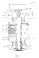
Figure 1 shows a plan view of a working machine; -
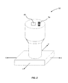
Figure 2 schematically shows a joystick for providing an input to a control system for controlling the working machine ofFigure 1 ; -
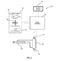
Figure 3 shows a portion of a control system for operating the working machine of -
Figure 1 ; -
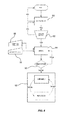
Figure 4 shows a different portion of the control system ofFigure 2 ; -
Figure 5 shows a further different portion of the control system ofFigure 2 ; and -
Figure 6 shows control logic for operating the working machine ofFigure 1 . - Referring to
Figure 1 , a working machine is indicated generally at 10. The workingmachine 10 is a materials handling vehicle, more particularly a telescopic handler. The workingmachine 10 includes aground engaging structure 12, abody 14 and a workingarm 16 pivotally connected to thebody 14 about a generally horizontal axis X-X. The workingarm 16 is connected to a rear of thebody 14 and extends to a front position of thebody 14. An attachment, in this embodiment ashovel 18, is connected to an end of the workingarm 16 positioned towards the front of thebody 14. Theshovel 18 is connected to the workingarm 16 via acarriage 17. - In the present embodiment the
ground engaging structure 12 includes fourwheels 20, but in alternative embodiments the ground engaging structure may include an alternative number of wheels or tracks. Thebody 14 is supported on theground engaging structure 12 and includes acab 22 from which a user can drive and operate the workingmachine 10. An engine (not shown) is provided within thebody 14 to provide motive power to the working machine, as well as to drive a pump (not shown) for a hydraulic system and an alternator (not shown) to power the electrical system. - In the present embodiment, the working
arm 16 is a telescopic arm having inner andouter portions - To pivot the working
arm 16 twohydraulic actuators body 14 and the workingarm 16. Extension of the hydraulic actuators pivots the working arm about a substantially horizontal axis X-X so as to move theshovel 18 away from the ground, and retraction of the hydraulic actuators pivots the working arm about axis X-X so as to move theshovel 18 towards the ground. - A further hydraulic actuator (not visible in
Figure 1 ) is provided within the workingarm 16 to extend and retract the telescopic arm, such that the telescopic arm increases and decreases in length. - A yet further hydraulic actuator (not visible in
Figure 1 ) acts between the workingarm 16 and thecarriage 17 to tilt theshovel 18, such that extension or retraction of the hydraulic actuator rotates the shovel about a second substantially horizontal axis Y-Y. - The working
machine 10 includes an electro-hydraulic ("servo") control system for controlling the hydraulic actuators of the workingarm 16 so as to control the position of the working arm, the length of the working arm, and the angular position of theshovel 18. Such control systems are advantageous in that they reduce the amount of mechanical linkages/hydraulic hoses within a working machine of this type, and also allow greater freedom for the positioning of controls (e.g. to locate the input on a rotatable seat or steering wheel), since only electrical cabling or a wireless transmitter needs to connect the input to an electronic control unit (ECU). - A user operates the working
machine 10 from thecab 22. Thecab 22 includes aseat 21, asteering wheel 23, and various other physical controls for operating the workingmachine 10. One of such physical control is ajoystick 52, shown inFigure 2 , which provides an input to the electro-hydraulic control system. In the present embodiment, the joystick is provided adjacent theseat 21 and is a digital joystick. In other embodiments, an analogue joystick may be used. - The
joystick 52 is moveable in an X-direction and a Y-direction, e.g. forwards and backwards, side to side, and positions within a plane defined by the X and Y directions. - During standard operation of the working
machine 10, referred to in the present application as operation in the positioning mode, movement of the joystick in the X-direction and/or Y-direction controls pivoting of the workingarm 16 and tilting of theshovel 18. Movement of the joystick in the X-direction, i.e. in the present embodiment forwards and backwards controls pivoting of the workingarm 16 about the axis X-X, and movement of the joystick in the Y-direction, i.e. in the present embodiment side to side controls tilting of theshovel 18 about axis Y-Y. - The
joystick 52 is linked to thecontrol system 32, part of which is shown inFigure 3 . Thecontrol system 32 includes aninput device 34 in the form of a position encoder in the base of the joystick, an electronic control unit (ECU) 36 configured to receive input signals from the input device and to emit output signals to controlvalves solenoids -
Valves hydraulic actuators - The
joystick 52 is configured to provide a mode of input to theinput device 34 such that movement of the joystick, for example in a rearwards direction, sends a positioning signal to the ECU. The positioning signal will contain information relating to the distance the joystick has been moved out of neutral, i.e. 0% to 100% from a neutral position. In the current embodiment, the signal is sent to the ECU via a CAN bus message (Controller Area Network bus message), in the present embodiment the control system uses the J1939 CAN bus. - The
ECU 36 receives the CAN bus message of joystick position and determines an electrical signal to send to thesolenoids solenoids solenoids valves 42, 44 (which in this embodiment are spool valves) to a position that permits flow of fluid to thehydraulic actuators joystick 52 out of neutral. Flow of fluid to thehydraulic actuators - In the present embodiment, the position of the
joystick 52 relative to the neutral position, i.e. 0 % to 100 % from the neutral position, is substantially proportional to the speed of movement the working arm. In the present embodiment, theECU 36 is configured such that movement between 0% and 2% does not initiate movement of the relevant hydraulic actuator. - The example has been described for rearwards movement of the
joystick 52 and lifting of the workingarm 16 from the body. However, it will be appreciated that movement of the joystick in a forward direction causes lowering of the working arm towards thebody 14 in a similar way. Movement of thejoystick 52 in the Y-direction also causes tilting of theshovel 18 in a similar manner. Thejoystick 52 of the present embodiment is configured to permit movement in both the X-direction and the Y-direction at the same time, permitting simultaneous lifting or lowering of the workingarm 16 and tilting of theshovel 18. - Referring back to
Figure 2 , in this embodiment, thejoystick 52 includes ascroll button 74. Movement of the scroll button in a forwards direction extends the workingarm 16 and movement of the scroll button in a rearwards direction retracts the workingarm 16. In alternative embodiments, an alternative type of input may be used, e.g. a mini joystick or slider-type switch. Movement of the scroll button in the forwards or rearwards direction causes extension or retraction of the working arm in a similar way as described for lifting and lowering the workingarm 16. - The
control system 32 of the present invention additionally permits the working machine to be operated in an oscillating mode that oscillates the working arm in a generally upward and downward direction about axis X-X, oscillates thecarriage 17 about axis Y-Y, and/or oscillates between a degree of extension and retraction of the workingarm 16. The oscillations are relatively rapid and have a relatively limited amplitude by comparison with typical positioning movements. As stated above, such oscillations are desirable in a number of different operating scenarios. - Referring to
Figures 2 and3 , thejoystick 52 further includes anactivation button 46 that engages the oscillation mode by sending an appropriate signal to theECU 36 via the CAN bus. In the oscillating mode, a desired intensity of oscillations is indicated by the position of the joystick in the X-direction and/or the Y-direction; the further the joystick is out of the neutral position the greater the intensity of the oscillations. - In the oscillating mode, the
ECU 36 includes logic that indicates a desired oscillation of the workingarm 16. In the present embodiment, a suitable algorithm in conjunction with a lookup table is used to calculate the amplitude and/or frequency of an oscillation based on the percentage intensity indicated by the position of the joystick. In this embodiment, the frequency is fixed, and the variation of intensity is a variation of amplitude only, but in other embodiments the amplitude may be fixed and the frequency varied, or both varied. - The algorithm and/or lookup table will vary depending on the type of machine and the intended use of the
machine 10. The skilled person will be familiar with how to calculate the desired frequency and/or amplitude based on a percentage intensity of oscillations. In alternative embodiments, a separate input may be provided for amplitude and frequency so that a user can vary these parameters independently. - The
ECU 36 sends a signal to thesolenoids valves hydraulic actuator 24, a series of pulses are sent to thesolenoids solenoid 37 is "on" when the pulsed signal sent to thesolenoid 38 is "off", and vice-versa. The voltage, current or length of the pulse is dependent upon the percentage intensity indicated by the oscillation signal. In a preferred embodiment the signal is transmitted to the solenoids as a pulse width modulation (PWM) control. - The
hydraulic actuators valve hydraulic actuators - When the
joystick 52 is in a neutral position and the oscillating mode activation button is depressed, although the ECU will receive an "oscillation mode active" message, no oscillation will in effect occur, because the neutral position indicates a zero oscillation intensity. - The control system is also supplied with a system enable
switch 56. The system enable switch is configured to send a signal to the ECU to indicate whether the oscillation mode should be available for use (e.g. to prevent inadvertent use of this mode during inappropriate operational scenarios). - Referring to
Figure 4 , thecontrol system 32 is also used to control thehydraulic actuator 58 that controls the angle of tilt of thecarriage 17. - Control of the tilt of the
carriage 17 also has two modes of operation; positioning mode and oscillating mode. The two modes work in a similar manner to that described for positioning of the workingarm 16. However, only onehydraulic actuator 58 is provided to tilt thecarriage 17, so only onevalve 60 and twosolenoids carriage 17. - Referring to
Figure 5 , control of the length of the workingarm 16 may also have two modes of operation; a positioning mode and an oscillating mode (although applications for the oscillating mode of the length of the working arm are considered more limited). The two modes work in a similar manner to that described for positioning of the working arm. However, only onehydraulic actuator 66 is provided to extend and retract the workingarm 16, so only onevalve 68 and twosolenoids - Operation of the working
machine 10 will now be described. Different uses of the workingmachine 10 are described to illustrate the operation, but these example operations are by way of example only and it is possible to use the workingmachine 10 for many other applications. - In a first example, an operator may be using the working
machine 10 to move and manipulate a material that is prone to sticking to theshovel 18, such as wet soil. - Firstly, a user switches the system enable
button 56 to indicate that the oscillating mode should be available. - To manipulate the material, a user moves the
joystick 52 to change the position of the workingarm 16 and to tilt theshovel 18, so as to e.g. pick up material and move it to another location. - To empty material from the
shovel 18, thejoystick 52 is moved to the left along the Y-axis to tilt theshovel 18 forwards. If when emptying the shovel some of the material remains in the shovel because it has become stuck, a user will wish to oscillate the shovel to dislodge this material. The process followed by the control system to enable this to occur is set out inFigure 6 . - Firstly, (at step 80) the
ECU 36 checks that the user has switched the system enablebutton 56 to enable oscillating mode. The ECU further monitors (at step 82) that the user has pressed theactivation button 46. If yes, the ECU now follows the oscillation mode logic for joystick inputs atstep 84. Accordingly, the ECU processes the signals corresponding to the intensity (86) and direction (88) of the joystick according to the oscillation logic instead of positioning logic. If the system enablebutton 56 or theactivation button 46 have not been activated, then the ECU does not continue with processing a command to oscillate theshovel 18. - In the present example, the
joystick 52 is displaced in the Y-axis which indicates that the shake should be in a tilt direction, i.e. theshovel 18 should be oscillated usinghydraulic actuator 58. - The ECU processes the CAN bus messages that indicate the position of the
joystick 52 to determine the voltage of the electric pulses that should be sent to thesolenoids - The ECU then checks at
step 90 the working machine master control ("MCO") to confirm no machine wide faults or unacceptable operating states exist (e.g. shovel payload too heavy for safe oscillation at the desired intensity). Only if no faults are indicated (i.e. MCO is not active) are the electric pulses are sent to thesolenoids - To oscillate the shovel 18 (at 92), a first electrical signal is sent to the
solenoid 62, which moves thevalve 60 to a position that permits fluid to flow from the pump to one end of the piston within the cylinder at a rate to achieve the desired amplitude of oscillation. After a predetermined length of time, the first electrical signal ceases and thesolenoid 62 closes. A second electrical signal is then sent to thesolenoid 64, which moves thevalve 60 to a position that permits fluid to flow from the pump to the other end of the piston within the cylinder. After a predetermined length of time, the electrical signal ceases and thesolenoid 64 closes. The ECU continues to open and close the solenoids to oscillate theshovel 18 until thejoystick 52 is moved to a neutral position and/or theactivation button 46 is pressed. - During the oscillating mode a user can change the amplitude of the oscillations by moving the
joystick 52 towards or away from a neutral position. - In the described example, the positioning mode and oscillating mode function separately. However, in alternative embodiments the positioning mode and oscillating mode may work simultaneously. This may be activated by a further switch (not shown) on the
joystick 52, by makingswitch 46 have three positions (off, exclusively oscillation, and combined oscillation and positioning), or may be automatically programmed. An example where this mechanism would be useful is transporting grain from one position to another. - To transport the grain a user moves the
joystick 52 in a left direction to tilt the shovel forward, and moves thejoystick 52 in a forward direction to move theshovel 18 downwards. Thescroll button 74 is then used to push theshovel 18 into a pile of grain, or alternatively the workingmachine 10 is driven forwards. - The
joystick 52 is then moved to the right to pivot move the shovel backwards (crowd) optionally in combination with some lifting of the working arm. - To level the grain in the
shovel 18 prior to transferring the grain e.g. to a trailer without spillage from the shovel, it is desirable to shake theshovel 18. Accordingly, a user presses theactivation button 46 on thejoystick 52, and as described the oscillation mode is activated. However, the shovel needs to be in an upright position to retain the grain in the shovel. As such, during the oscillation mode, the shovel simultaneously tilts more towards an upright position, whilst also oscillating. Tilting to the upright position is done slowly. Once in the upright position and the grain is levelled off, the oscillating mode is deactivated by ceasing to press theactivation button 46 or returning thejoystick 52 to a neutral position. - The working
machine 10 may be used for a variety of other applications, by way of example only, these include distributing material such as aggregate from the shovel, breaking bales, breaking livestock feed cake, or breaking bundles. To break the bales, feed cake or bundles, it may be desirable to directly oscillate the workingarm 16 instead of thecarriage 17. - Advantageously the invention provides a method for oscillating an attachment of a working
machine 10 that uses electro-hydraulic controls. - Further the working
machine 10 provides a method of repeatably and adjustably oscillating an attachment (e.g. shovel 18). Providing all the input features on thejoystick 52 means that a user can easily actuate the oscillating mode without the need to take their hand off the joystick. This provides both ergonomic advantages and the ability to simultaneously operate in the positioning mode and the oscillating mode. - Proportional control of the rate of change of position of the shovel relative to the body and also proportional control of the oscillations improves ease of use of the working machine because an operator an easily and repeatably set a desired intensity of oscillations.
- Although the invention has been described above with reference to one or more preferred embodiments, it will be appreciated that various changes or modifications may be made without departing from the scope of the invention as defined in the appended claims.
- For example, the
control system 32 could be applied to an alternative types of working machines, for example backhoe loader (both backhoe and loader working arms), slew excavators, loading shovels, dump trucks (tipping mechanisms thereof being in effect the working arm), skid steer loaders, wheeled loaders etc. Additionally, an oscillation mode may be used on auxiliary hydraulic services that are provided on machines of these types to provide additional oscillating functionality to certain attachments that are connected to the carriage and incorporate hydraulic actuators (such as 6-in-1 shovels, grabs etc). - Further, an alternative method of controlling movement of the hydraulic actuator may be used. For example, a potentiometer input may be used to indicate intensity instead of the button and joystick combination.
- Instead of the controls being provided on a single joystick, multiple joysticks may be used, or dials on e.g. a dashboard may be used. In alternative embodiments a jog/scroll wheel or mini joystick may be provided on the joystick and the scroll wheel or mini joystick may provide the oscillation input. The joystick may movable on one axis only, rather than two.
- In the present embodiment, the oscillation amplitude is selected using an oscillation intensity parameter. But, in alternative embodiments the amplitude and frequency may be independently variable. Further alternatively, a time based logic, or a time and amplitude based logic instead of an amplitude based logic may be used to control the oscillations.
- It will be appreciated that the direction of motion of the working arm and/or carriage, and/or the extension and retraction of the working arm has been described with reference to an exemplary direction of movement of the joystick and/or scroll button, but in alternative embodiments, a given direction of motion of the working arm and/or carriage, and/or the extension and retraction of the working arm may correspond to an alternative direction of movement of the joystick and/or scroll button. The exemplary embodiments have been described in relation to an electro-hydraulic actuation of working arms. However in other embodiments the invention may be applied to working machines having working arms moved by electric linear actuators.
Claims (15)
- A working machine comprising:a ground engaging structure;a propulsion system for moving the working machine via the ground engaging structure;a body supported on the ground engaging structure;a working arm connected to the body and having a carriage at one end for receiving an attachment; anda control system for selectively oscillating the carriage,wherein the control system comprises:an actuator configured and arranged to selectively oscillate the carriage;an electronic controller configured to control the actuator; anda user input device in communication with the controller;wherein the user input device comprises an oscillation input configured to selectively transmit an oscillation signal to the electronic controller to indicate a desired amplitude and/or frequency of oscillation of the carriage, wherein the oscillation input is variable to alter the oscillation signal transmitted to the electronic controller; andwherein the electronic controller is configured to upon receipt of the oscillation signal selectively activate the actuator to oscillate the carriage at the desired frequency and/or amplitude indicated by the oscillation signal.
- The working machine according to claim 1, wherein the actuator is configured to oscillate the carriage directly or indirectly.
- The working machine according to any one of the previous claims, wherein the oscillation signal includes an intensity indicator, and the controller is configured to use an algorithm and/or lookup table for transforming the intensity indicator to a desired frequency and/or amplitude of oscillation.
- The working machine according to any one of the previous claims, wherein the input device comprises a position input configured to transmit a position signal to the electronic controller to indicate a desired change of position of the carriage, and wherein the electronic controller is configured to upon receipt of the position signal activate the actuator to move the carriage as desired, preferably wherein the change of position is a change of angular position and/or a change in spatial position with respect to the body.
- The working machine according to claim 4, wherein the controller is configured to signal actuation of the actuator to move the carriage from a first position to a second position simultaneously whilst oscillating the carriage at the desired amplitude and/or frequency.
- The working machine according to claim 5, wherein simultaneous movement and oscillation of the carriage is selectively applied dependent upon a signal received from an indicator of the control system, preferably wherein the indicator is a button or switch provided on a user interface of the working machine.
- The working machine according to claim 5, wherein the controller is configured to move the carriage in a desired direction at a slower rate when simultaneously moving and oscillating the carriage than when only moving the carriage.
- The working machine according to claim 4, wherein the position input comprises an input device that a user can move to indicate the desired change of position of the carriage.
- The working machine according to claim 8, wherein the desired change of position indicated by the position signal is proportional to the position of the input device with respect to a neutral position of the input device.
- The working machine according to claim 8 or 9, wherein the input device is configured such that the oscillation signal transmitted to the controller is dependent upon the position of the input device, preferably wherein the desired frequency and/or amplitude of the oscillations indicated by the oscillation signal is proportional to the position of the input device with respect to a neutral position of the input device.
- The working machine according to any one of claims 3 to 10, wherein the input device is a joystick, optionally an analogue or digital joystick.
- The working machine according to claim 11, wherein the controller is configured to detect when the joystick is in a neutral position and only send a signal to actuate oscillations of the carriage when the joystick is out of the neutral position.
- A control system for a working machine of the type having a working arm connected to a body and a carriage at one end of the working arm for mounting an attachment thereto; the working machine having two modes of operation, a first mode where the position of the attachment is adjustable relative to the body, and a second mode where the attachment is oscillated relative to the body, movement of the attachment being achieved using an actuator; the control system comprising:an input device having a position input configured to receive a desired change of position of a carriage of a working machine relative to a body of a working machine, and an oscillation input configured to receive an indication from a user that a carriage of a working machine should be oscillated and configured to receive an input from a user indicating the frequency and/or amplitude of the oscillations; anda controller;wherein the position input is configured to send a signal to the controller indicating the desired rate of change of position of the carriage, and the oscillation input is configured to send a signal to the controller indicating when the carriage should be oscillated and the frequency and/or amplitude of said oscillation; andwherein the controller is configured to, upon receipt of the position signal and/or oscillation signal, send a signal to an actuator of a working machine to move the carriage at the desired rate of change of position and/or to oscillate the carriage at the desired frequency and/or amplitude of oscillation.
- A method of operation of a working machine of the type having a ground engaging structure; a propulsion system for moving the working machine via the ground engaging structure; a body supported on the ground engaging structure; a working arm connected to the body and a carriage at one end of the working arm for receiving an attachment; and a control system according to claim 29, and wherein the control system includes a joystick; the method comprising:moving the joystick of the working machine to move the carriage, the rate of change of position of the carriage corresponding to the position of the joystick with respect to a neutral position; andinputting a desired amplitude and/or frequency of oscillations of the carriage and initiating oscillations of the carriage.
- The method according to claim 14, comprising adjusting the desired amplitude and/or frequency during oscillation of the carriage, preferably wherein the desired amplitude and/or frequency is inputted using the joystick used to move the carriage.
Priority Applications (1)
| Application Number | Priority Date | Filing Date | Title |
|---|---|---|---|
| EP21184103.6A EP3909907A1 (en) | 2013-05-20 | 2014-05-19 | Working machine with implement shaking function |
Applications Claiming Priority (1)
| Application Number | Priority Date | Filing Date | Title |
|---|---|---|---|
| GB1309023.8A GB2514346B (en) | 2013-05-20 | 2013-05-20 | Working machine and control system |
Related Child Applications (2)
| Application Number | Title | Priority Date | Filing Date |
|---|---|---|---|
| EP21184103.6A Division-Into EP3909907A1 (en) | 2013-05-20 | 2014-05-19 | Working machine with implement shaking function |
| EP21184103.6A Division EP3909907A1 (en) | 2013-05-20 | 2014-05-19 | Working machine with implement shaking function |
Publications (2)
| Publication Number | Publication Date |
|---|---|
| EP2805910A1 true EP2805910A1 (en) | 2014-11-26 |
| EP2805910B1 EP2805910B1 (en) | 2021-12-01 |
Family
ID=48747009
Family Applications (2)
| Application Number | Title | Priority Date | Filing Date |
|---|---|---|---|
| EP21184103.6A Pending EP3909907A1 (en) | 2013-05-20 | 2014-05-19 | Working machine with implement shaking function |
| EP14168908.3A Active EP2805910B1 (en) | 2013-05-20 | 2014-05-19 | Working machine and control system |
Family Applications Before (1)
| Application Number | Title | Priority Date | Filing Date |
|---|---|---|---|
| EP21184103.6A Pending EP3909907A1 (en) | 2013-05-20 | 2014-05-19 | Working machine with implement shaking function |
Country Status (7)
| Country | Link |
|---|---|
| US (2) | US9556589B2 (en) |
| EP (2) | EP3909907A1 (en) |
| JP (1) | JP2014227828A (en) |
| CN (1) | CN104179217B (en) |
| AU (1) | AU2014202689B2 (en) |
| ES (1) | ES2900625T3 (en) |
| GB (1) | GB2514346B (en) |
Cited By (3)
| Publication number | Priority date | Publication date | Assignee | Title |
|---|---|---|---|---|
| EP3358087A1 (en) | 2017-02-03 | 2018-08-08 | Manitou Bf | Construction machine, in particular for construction site, and method for controlling such a machine |
| WO2021247095A1 (en) * | 2020-06-03 | 2021-12-09 | Parker-Hannifin Corporation | Sensing and control of a rapidly-commanded hydraulic actuator |
| IT202100018038A1 (en) * | 2021-07-08 | 2023-01-08 | Cnh Ind Italia Spa | HYDRAULIC CONTROL SYSTEM FOR CONTROLLING A WORK VEHICLE OPERATION AND RELATED METHOD |
Families Citing this family (7)
| Publication number | Priority date | Publication date | Assignee | Title |
|---|---|---|---|---|
| US8860337B2 (en) * | 2009-05-18 | 2014-10-14 | Resonant Systems, Inc. | Linear vibration modules and linear-resonant vibration modules |
| JP6860458B2 (en) * | 2017-09-15 | 2021-04-14 | 日立建機株式会社 | Work machine |
| US10597845B2 (en) | 2017-09-27 | 2020-03-24 | Deere & Company | Implement vibration system and method |
| CN108005801B (en) * | 2017-12-08 | 2020-03-31 | 三一重机有限公司 | Power response method and device |
| DE202018100592U1 (en) * | 2018-02-02 | 2019-05-03 | Liebherr-Hydraulikbagger Gmbh | Operating device for a working device and working device with appropriate operating device |
| CN117500986A (en) * | 2021-06-28 | 2024-02-02 | 斗山山猫北美公司 | System and method for controlling an excavator and other power machines |
| US11761170B2 (en) * | 2021-11-17 | 2023-09-19 | Robert Bosch Gmbh | Apparatus for facilitating bucket movement |
Citations (6)
| Publication number | Priority date | Publication date | Assignee | Title |
|---|---|---|---|---|
| GB1187527A (en) * | 1967-10-26 | 1970-04-08 | Salzgitter Maschinen Ag | Mobile Loader |
| US5287699A (en) * | 1990-01-16 | 1994-02-22 | Kabushiki Kaisha Komatsu Seisakusho | Automatic vibration method and device for hydraulic drilling machine |
| JPH08165678A (en) * | 1994-12-12 | 1996-06-25 | Yanmar Diesel Engine Co Ltd | Excavation control device |
| US7117952B2 (en) * | 2004-03-12 | 2006-10-10 | Clark Equipment Company | Automated attachment vibration system |
| US20060248885A1 (en) * | 2005-05-06 | 2006-11-09 | Buckmier Jason M | Apparatus and method for controlling work tool vibration |
| US7270046B2 (en) * | 2005-12-12 | 2007-09-18 | Husco International, Inc. | Integrated valve assembly and computer controller for a distributed hydraulic control system |
Family Cites Families (16)
| Publication number | Priority date | Publication date | Assignee | Title |
|---|---|---|---|---|
| CN86210230U (en) * | 1986-12-13 | 1987-12-16 | 吉林工业大学 | Frame vibration shovel blade for loading machine |
| KR0141978B1 (en) * | 1990-01-16 | 1999-02-18 | 카타다 테쯔야 | Automatic vibration method and apparatus for hydraulic excavator |
| US5235809A (en) * | 1991-09-09 | 1993-08-17 | Vickers, Incorporated | Hydraulic circuit for shaking a bucket on a vehicle |
| JPH0693630A (en) * | 1992-09-11 | 1994-04-05 | Hitachi Constr Mach Co Ltd | Construction equipment service bucket control device |
| JPH0771057A (en) * | 1993-06-30 | 1995-03-14 | Kubota Corp | Back-hoe |
| KR100328217B1 (en) | 1996-04-30 | 2002-06-26 | 볼보 컨스트럭션 이키프먼트 홀딩 스웨덴 에이비 | Automatic Vibration System and Method of Hydraulic Construction Machinery |
| US6763661B2 (en) * | 2002-05-07 | 2004-07-20 | Husco International, Inc. | Apparatus and method for providing vibration to an appendage of a work vehicle |
| US6757992B1 (en) * | 2003-01-14 | 2004-07-06 | New Holland North America, Inc. | Skid steer loader bucket shaker |
| KR100621978B1 (en) * | 2004-03-10 | 2006-09-14 | 볼보 컨스트럭션 이키프먼트 홀딩 스웨덴 에이비 | automatic vibration device and method of heavy equipment |
| US7062350B2 (en) * | 2004-10-18 | 2006-06-13 | Caterpillar Inc. | Control method and apparatus for a work tool |
| US7726125B2 (en) * | 2007-07-31 | 2010-06-01 | Caterpillar Inc. | Hydraulic circuit for rapid bucket shake out |
| KR20110071907A (en) * | 2009-12-22 | 2011-06-29 | 두산인프라코어 주식회사 | Apparatus and method for controling eletronic oil pressure using variable behavior characteristic |
| CN201826245U (en) * | 2010-03-24 | 2011-05-11 | 宋建国 | Hydraulic vibrating rammer |
| JP5676739B2 (en) * | 2011-02-22 | 2015-02-25 | 日立建機株式会社 | Wheel loader |
| CN102587446A (en) * | 2012-03-27 | 2012-07-18 | 昆山航天智能技术有限公司 | Hydraulic control shock excitation equipment for vibration excavator |
| EP2674533B1 (en) * | 2012-06-12 | 2019-09-04 | HAWE Hydraulik SE | Electro-hydraulic control system |
-
2013
- 2013-05-20 GB GB1309023.8A patent/GB2514346B/en active Active
-
2014
- 2014-05-15 US US14/279,103 patent/US9556589B2/en active Active
- 2014-05-16 AU AU2014202689A patent/AU2014202689B2/en active Active
- 2014-05-19 JP JP2014103051A patent/JP2014227828A/en active Pending
- 2014-05-19 ES ES14168908T patent/ES2900625T3/en active Active
- 2014-05-19 EP EP21184103.6A patent/EP3909907A1/en active Pending
- 2014-05-19 EP EP14168908.3A patent/EP2805910B1/en active Active
- 2014-05-20 CN CN201410213655.7A patent/CN104179217B/en not_active Expired - Fee Related
-
2016
- 2016-09-30 US US15/282,103 patent/US10145085B2/en active Active
Patent Citations (6)
| Publication number | Priority date | Publication date | Assignee | Title |
|---|---|---|---|---|
| GB1187527A (en) * | 1967-10-26 | 1970-04-08 | Salzgitter Maschinen Ag | Mobile Loader |
| US5287699A (en) * | 1990-01-16 | 1994-02-22 | Kabushiki Kaisha Komatsu Seisakusho | Automatic vibration method and device for hydraulic drilling machine |
| JPH08165678A (en) * | 1994-12-12 | 1996-06-25 | Yanmar Diesel Engine Co Ltd | Excavation control device |
| US7117952B2 (en) * | 2004-03-12 | 2006-10-10 | Clark Equipment Company | Automated attachment vibration system |
| US20060248885A1 (en) * | 2005-05-06 | 2006-11-09 | Buckmier Jason M | Apparatus and method for controlling work tool vibration |
| US7270046B2 (en) * | 2005-12-12 | 2007-09-18 | Husco International, Inc. | Integrated valve assembly and computer controller for a distributed hydraulic control system |
Cited By (5)
| Publication number | Priority date | Publication date | Assignee | Title |
|---|---|---|---|---|
| EP3358087A1 (en) | 2017-02-03 | 2018-08-08 | Manitou Bf | Construction machine, in particular for construction site, and method for controlling such a machine |
| FR3062662A1 (en) * | 2017-02-03 | 2018-08-10 | Manitou Bf | WORK EQUIPMENT, IN PARTICULAR SITE, AND METHOD FOR CONTROLLING SUCH A GEAR |
| WO2021247095A1 (en) * | 2020-06-03 | 2021-12-09 | Parker-Hannifin Corporation | Sensing and control of a rapidly-commanded hydraulic actuator |
| IT202100018038A1 (en) * | 2021-07-08 | 2023-01-08 | Cnh Ind Italia Spa | HYDRAULIC CONTROL SYSTEM FOR CONTROLLING A WORK VEHICLE OPERATION AND RELATED METHOD |
| EP4116505A1 (en) * | 2021-07-08 | 2023-01-11 | CNH Industrial Italia S.p.A. | Hydraulic control system for controlling an operation of a work vehicle and related method |
Also Published As
| Publication number | Publication date |
|---|---|
| GB201309023D0 (en) | 2013-07-03 |
| GB2514346A (en) | 2014-11-26 |
| US20170016207A1 (en) | 2017-01-19 |
| US20140343804A1 (en) | 2014-11-20 |
| AU2014202689B2 (en) | 2018-03-15 |
| GB2514346B (en) | 2017-02-08 |
| CN104179217A (en) | 2014-12-03 |
| AU2014202689A1 (en) | 2014-12-04 |
| CN104179217B (en) | 2019-05-17 |
| JP2014227828A (en) | 2014-12-08 |
| US10145085B2 (en) | 2018-12-04 |
| EP2805910B1 (en) | 2021-12-01 |
| US9556589B2 (en) | 2017-01-31 |
| EP3909907A1 (en) | 2021-11-17 |
| ES2900625T3 (en) | 2022-03-17 |
Similar Documents
| Publication | Publication Date | Title |
|---|---|---|
| US10145085B2 (en) | Working machine and control system | |
| US5537818A (en) | Method for controlling an implement of a work machine | |
| CA2486037C (en) | Pattern selector valve for control levers of a work vehicle | |
| US20140271078A1 (en) | Lift arm structure with an articulated knee portion | |
| US20050102866A1 (en) | Multi-function work machine | |
| EP2660478B1 (en) | Boom-swivel compound drive hydraulic control system of construction machine | |
| US20180100290A1 (en) | Material Handling Machine with Bucket Shake Control System and Method | |
| US20090055058A1 (en) | Method of Controlling a Working Machine | |
| JPH111942A (en) | Control method and device for tool of work machine | |
| EP0637650A1 (en) | Steering switch integral with an implement control lever | |
| CN111287230B (en) | Attachment configurable system for a work machine | |
| US20060064221A1 (en) | Operator selectable control pattern | |
| CN109072584B (en) | Control system for work vehicle and control method for work vehicle | |
| US20200181880A1 (en) | Attachment-configurable system for a work machine | |
| EP3569771B1 (en) | A working machine joystick assembly | |
| CN111823856B (en) | System and method for controlling a work vehicle | |
| JP2012017589A (en) | Control device of front loader | |
| JP3461281B2 (en) | Work machine control device for construction machinery | |
| JP7241742B2 (en) | Methods for controlling the operation of hydraulic control systems, work machines, and work attachments | |
| EP4283050A1 (en) | A working machine | |
| WO2024004300A1 (en) | Oil pressure control device |
Legal Events
| Date | Code | Title | Description |
|---|---|---|---|
| PUAI | Public reference made under article 153(3) epc to a published international application that has entered the european phase |
Free format text: ORIGINAL CODE: 0009012 |
|
| 17P | Request for examination filed |
Effective date: 20140519 |
|
| AK | Designated contracting states |
Kind code of ref document: A1 Designated state(s): AL AT BE BG CH CY CZ DE DK EE ES FI FR GB GR HR HU IE IS IT LI LT LU LV MC MK MT NL NO PL PT RO RS SE SI SK SM TR |
|
| AX | Request for extension of the european patent |
Extension state: BA ME |
|
| R17P | Request for examination filed (corrected) |
Effective date: 20150316 |
|
| RBV | Designated contracting states (corrected) |
Designated state(s): AL AT BE BG CH CY CZ DE DK EE ES FI FR GB GR HR HU IE IS IT LI LT LU LV MC MK MT NL NO PL PT RO RS SE SI SK SM TR |
|
| TPAC | Observations filed by third parties |
Free format text: ORIGINAL CODE: EPIDOSNTIPA |
|
| STAA | Information on the status of an ep patent application or granted ep patent |
Free format text: STATUS: EXAMINATION IS IN PROGRESS |
|
| 17Q | First examination report despatched |
Effective date: 20200408 |
|
| STAA | Information on the status of an ep patent application or granted ep patent |
Free format text: STATUS: EXAMINATION IS IN PROGRESS |
|
| TPAC | Observations filed by third parties |
Free format text: ORIGINAL CODE: EPIDOSNTIPA |
|
| GRAP | Despatch of communication of intention to grant a patent |
Free format text: ORIGINAL CODE: EPIDOSNIGR1 |
|
| STAA | Information on the status of an ep patent application or granted ep patent |
Free format text: STATUS: GRANT OF PATENT IS INTENDED |
|
| RIC1 | Information provided on ipc code assigned before grant |
Ipc: E02F 9/20 20060101ALI20210413BHEP Ipc: E02F 3/40 20060101ALI20210413BHEP Ipc: E02F 9/22 20060101ALI20210413BHEP Ipc: E02F 3/34 20060101ALI20210413BHEP Ipc: B66F 9/065 20060101AFI20210413BHEP |
|
| INTG | Intention to grant announced |
Effective date: 20210429 |
|
| GRAJ | Information related to disapproval of communication of intention to grant by the applicant or resumption of examination proceedings by the epo deleted |
Free format text: ORIGINAL CODE: EPIDOSDIGR1 |
|
| STAA | Information on the status of an ep patent application or granted ep patent |
Free format text: STATUS: EXAMINATION IS IN PROGRESS |
|
| GRAP | Despatch of communication of intention to grant a patent |
Free format text: ORIGINAL CODE: EPIDOSNIGR1 |
|
| STAA | Information on the status of an ep patent application or granted ep patent |
Free format text: STATUS: GRANT OF PATENT IS INTENDED |
|
| INTC | Intention to grant announced (deleted) | ||
| INTG | Intention to grant announced |
Effective date: 20210702 |
|
| RAP3 | Party data changed (applicant data changed or rights of an application transferred) |
Owner name: J.C. BAMFORD EXCAVATORS LIMITED |
|
| GRAS | Grant fee paid |
Free format text: ORIGINAL CODE: EPIDOSNIGR3 |
|
| GRAA | (expected) grant |
Free format text: ORIGINAL CODE: 0009210 |
|
| STAA | Information on the status of an ep patent application or granted ep patent |
Free format text: STATUS: THE PATENT HAS BEEN GRANTED |
|
| AK | Designated contracting states |
Kind code of ref document: B1 Designated state(s): AL AT BE BG CH CY CZ DE DK EE ES FI FR GB GR HR HU IE IS IT LI LT LU LV MC MK MT NL NO PL PT RO RS SE SI SK SM TR |
|
| REG | Reference to a national code |
Ref country code: GB Ref legal event code: FG4D |
|
| REG | Reference to a national code |
Ref country code: AT Ref legal event code: REF Ref document number: 1451609 Country of ref document: AT Kind code of ref document: T Effective date: 20211215 Ref country code: CH Ref legal event code: EP |
|
| REG | Reference to a national code |
Ref country code: IE Ref legal event code: FG4D |
|
| REG | Reference to a national code |
Ref country code: DE Ref legal event code: R096 Ref document number: 602014081478 Country of ref document: DE |
|
| REG | Reference to a national code |
Ref country code: ES Ref legal event code: FG2A Ref document number: 2900625 Country of ref document: ES Kind code of ref document: T3 Effective date: 20220317 |
|
| REG | Reference to a national code |
Ref country code: LT Ref legal event code: MG9D |
|
| REG | Reference to a national code |
Ref country code: NL Ref legal event code: MP Effective date: 20211201 |
|
| PG25 | Lapsed in a contracting state [announced via postgrant information from national office to epo] |
Ref country code: RS Free format text: LAPSE BECAUSE OF FAILURE TO SUBMIT A TRANSLATION OF THE DESCRIPTION OR TO PAY THE FEE WITHIN THE PRESCRIBED TIME-LIMIT Effective date: 20211201 Ref country code: LT Free format text: LAPSE BECAUSE OF FAILURE TO SUBMIT A TRANSLATION OF THE DESCRIPTION OR TO PAY THE FEE WITHIN THE PRESCRIBED TIME-LIMIT Effective date: 20211201 Ref country code: FI Free format text: LAPSE BECAUSE OF FAILURE TO SUBMIT A TRANSLATION OF THE DESCRIPTION OR TO PAY THE FEE WITHIN THE PRESCRIBED TIME-LIMIT Effective date: 20211201 Ref country code: BG Free format text: LAPSE BECAUSE OF FAILURE TO SUBMIT A TRANSLATION OF THE DESCRIPTION OR TO PAY THE FEE WITHIN THE PRESCRIBED TIME-LIMIT Effective date: 20220301 |
|
| PG25 | Lapsed in a contracting state [announced via postgrant information from national office to epo] |
Ref country code: SE Free format text: LAPSE BECAUSE OF FAILURE TO SUBMIT A TRANSLATION OF THE DESCRIPTION OR TO PAY THE FEE WITHIN THE PRESCRIBED TIME-LIMIT Effective date: 20211201 Ref country code: PL Free format text: LAPSE BECAUSE OF FAILURE TO SUBMIT A TRANSLATION OF THE DESCRIPTION OR TO PAY THE FEE WITHIN THE PRESCRIBED TIME-LIMIT Effective date: 20211201 Ref country code: NO Free format text: LAPSE BECAUSE OF FAILURE TO SUBMIT A TRANSLATION OF THE DESCRIPTION OR TO PAY THE FEE WITHIN THE PRESCRIBED TIME-LIMIT Effective date: 20220301 Ref country code: LV Free format text: LAPSE BECAUSE OF FAILURE TO SUBMIT A TRANSLATION OF THE DESCRIPTION OR TO PAY THE FEE WITHIN THE PRESCRIBED TIME-LIMIT Effective date: 20211201 Ref country code: HR Free format text: LAPSE BECAUSE OF FAILURE TO SUBMIT A TRANSLATION OF THE DESCRIPTION OR TO PAY THE FEE WITHIN THE PRESCRIBED TIME-LIMIT Effective date: 20211201 Ref country code: GR Free format text: LAPSE BECAUSE OF FAILURE TO SUBMIT A TRANSLATION OF THE DESCRIPTION OR TO PAY THE FEE WITHIN THE PRESCRIBED TIME-LIMIT Effective date: 20220302 |
|
| PG25 | Lapsed in a contracting state [announced via postgrant information from national office to epo] |
Ref country code: NL Free format text: LAPSE BECAUSE OF FAILURE TO SUBMIT A TRANSLATION OF THE DESCRIPTION OR TO PAY THE FEE WITHIN THE PRESCRIBED TIME-LIMIT Effective date: 20211201 |
|
| PG25 | Lapsed in a contracting state [announced via postgrant information from national office to epo] |
Ref country code: SM Free format text: LAPSE BECAUSE OF FAILURE TO SUBMIT A TRANSLATION OF THE DESCRIPTION OR TO PAY THE FEE WITHIN THE PRESCRIBED TIME-LIMIT Effective date: 20211201 Ref country code: SK Free format text: LAPSE BECAUSE OF FAILURE TO SUBMIT A TRANSLATION OF THE DESCRIPTION OR TO PAY THE FEE WITHIN THE PRESCRIBED TIME-LIMIT Effective date: 20211201 Ref country code: RO Free format text: LAPSE BECAUSE OF FAILURE TO SUBMIT A TRANSLATION OF THE DESCRIPTION OR TO PAY THE FEE WITHIN THE PRESCRIBED TIME-LIMIT Effective date: 20211201 Ref country code: PT Free format text: LAPSE BECAUSE OF FAILURE TO SUBMIT A TRANSLATION OF THE DESCRIPTION OR TO PAY THE FEE WITHIN THE PRESCRIBED TIME-LIMIT Effective date: 20220401 Ref country code: EE Free format text: LAPSE BECAUSE OF FAILURE TO SUBMIT A TRANSLATION OF THE DESCRIPTION OR TO PAY THE FEE WITHIN THE PRESCRIBED TIME-LIMIT Effective date: 20211201 Ref country code: CZ Free format text: LAPSE BECAUSE OF FAILURE TO SUBMIT A TRANSLATION OF THE DESCRIPTION OR TO PAY THE FEE WITHIN THE PRESCRIBED TIME-LIMIT Effective date: 20211201 |
|
| REG | Reference to a national code |
Ref country code: DE Ref legal event code: R026 Ref document number: 602014081478 Country of ref document: DE |
|
| PLBI | Opposition filed |
Free format text: ORIGINAL CODE: 0009260 |
|
| PG25 | Lapsed in a contracting state [announced via postgrant information from national office to epo] |
Ref country code: IS Free format text: LAPSE BECAUSE OF FAILURE TO SUBMIT A TRANSLATION OF THE DESCRIPTION OR TO PAY THE FEE WITHIN THE PRESCRIBED TIME-LIMIT Effective date: 20220401 |
|
| 26 | Opposition filed |
Opponent name: MANITOU BF Effective date: 20220831 |
|
| PLAX | Notice of opposition and request to file observation + time limit sent |
Free format text: ORIGINAL CODE: EPIDOSNOBS2 |
|
| PG25 | Lapsed in a contracting state [announced via postgrant information from national office to epo] |
Ref country code: DK Free format text: LAPSE BECAUSE OF FAILURE TO SUBMIT A TRANSLATION OF THE DESCRIPTION OR TO PAY THE FEE WITHIN THE PRESCRIBED TIME-LIMIT Effective date: 20211201 Ref country code: AL Free format text: LAPSE BECAUSE OF FAILURE TO SUBMIT A TRANSLATION OF THE DESCRIPTION OR TO PAY THE FEE WITHIN THE PRESCRIBED TIME-LIMIT Effective date: 20211201 |
|
| PG25 | Lapsed in a contracting state [announced via postgrant information from national office to epo] |
Ref country code: SI Free format text: LAPSE BECAUSE OF FAILURE TO SUBMIT A TRANSLATION OF THE DESCRIPTION OR TO PAY THE FEE WITHIN THE PRESCRIBED TIME-LIMIT Effective date: 20211201 |
|
| REG | Reference to a national code |
Ref country code: CH Ref legal event code: PL |
|
| REG | Reference to a national code |
Ref country code: BE Ref legal event code: MM Effective date: 20220531 |
|
| PG25 | Lapsed in a contracting state [announced via postgrant information from national office to epo] |
Ref country code: MC Free format text: LAPSE BECAUSE OF FAILURE TO SUBMIT A TRANSLATION OF THE DESCRIPTION OR TO PAY THE FEE WITHIN THE PRESCRIBED TIME-LIMIT Effective date: 20211201 Ref country code: LU Free format text: LAPSE BECAUSE OF NON-PAYMENT OF DUE FEES Effective date: 20220519 Ref country code: LI Free format text: LAPSE BECAUSE OF NON-PAYMENT OF DUE FEES Effective date: 20220531 Ref country code: CH Free format text: LAPSE BECAUSE OF NON-PAYMENT OF DUE FEES Effective date: 20220531 |
|
| PLBB | Reply of patent proprietor to notice(s) of opposition received |
Free format text: ORIGINAL CODE: EPIDOSNOBS3 |
|
| PG25 | Lapsed in a contracting state [announced via postgrant information from national office to epo] |
Ref country code: IE Free format text: LAPSE BECAUSE OF NON-PAYMENT OF DUE FEES Effective date: 20220519 |
|
| PG25 | Lapsed in a contracting state [announced via postgrant information from national office to epo] |
Ref country code: BE Free format text: LAPSE BECAUSE OF NON-PAYMENT OF DUE FEES Effective date: 20220531 |
|
| P01 | Opt-out of the competence of the unified patent court (upc) registered |
Effective date: 20230520 |
|
| PGFP | Annual fee paid to national office [announced via postgrant information from national office to epo] |
Ref country code: IT Payment date: 20230522 Year of fee payment: 10 Ref country code: FR Payment date: 20230526 Year of fee payment: 10 Ref country code: DE Payment date: 20230519 Year of fee payment: 10 |
|
| PGFP | Annual fee paid to national office [announced via postgrant information from national office to epo] |
Ref country code: AT Payment date: 20230522 Year of fee payment: 10 |
|
| PGFP | Annual fee paid to national office [announced via postgrant information from national office to epo] |
Ref country code: GB Payment date: 20230516 Year of fee payment: 10 Ref country code: ES Payment date: 20230725 Year of fee payment: 10 |
|
| REG | Reference to a national code |
Ref country code: AT Ref legal event code: UEP Ref document number: 1451609 Country of ref document: AT Kind code of ref document: T Effective date: 20211201 |
|
| PG25 | Lapsed in a contracting state [announced via postgrant information from national office to epo] |
Ref country code: HU Free format text: LAPSE BECAUSE OF FAILURE TO SUBMIT A TRANSLATION OF THE DESCRIPTION OR TO PAY THE FEE WITHIN THE PRESCRIBED TIME-LIMIT; INVALID AB INITIO Effective date: 20140519 |