EP2805880A1 - Jet synthétique à soufflet - Google Patents
Jet synthétique à soufflet Download PDFInfo
- Publication number
- EP2805880A1 EP2805880A1 EP14168234.4A EP14168234A EP2805880A1 EP 2805880 A1 EP2805880 A1 EP 2805880A1 EP 14168234 A EP14168234 A EP 14168234A EP 2805880 A1 EP2805880 A1 EP 2805880A1
- Authority
- EP
- European Patent Office
- Prior art keywords
- flap
- aperture
- chamber
- sidewall
- hinged
- Prior art date
- Legal status (The legal status is an assumption and is not a legal conclusion. Google has not performed a legal analysis and makes no representation as to the accuracy of the status listed.)
- Granted
Links
- 230000033001 locomotion Effects 0.000 claims abstract description 48
- 239000012530 fluid Substances 0.000 claims abstract description 32
- 230000007246 mechanism Effects 0.000 claims description 26
- 238000000034 method Methods 0.000 claims description 23
- 239000000463 material Substances 0.000 claims description 11
- 230000008878 coupling Effects 0.000 claims description 9
- 238000010168 coupling process Methods 0.000 claims description 9
- 238000005859 coupling reaction Methods 0.000 claims description 9
- 238000009826 distribution Methods 0.000 claims description 8
- 238000007789 sealing Methods 0.000 claims description 6
- 238000003860 storage Methods 0.000 description 18
- 238000004891 communication Methods 0.000 description 13
- 238000004519 manufacturing process Methods 0.000 description 13
- 238000012545 processing Methods 0.000 description 12
- 238000013461 design Methods 0.000 description 9
- 230000002085 persistent effect Effects 0.000 description 8
- 239000012528 membrane Substances 0.000 description 5
- 230000008569 process Effects 0.000 description 5
- 230000006870 function Effects 0.000 description 4
- 230000010354 integration Effects 0.000 description 3
- 238000012423 maintenance Methods 0.000 description 3
- 238000005086 pumping Methods 0.000 description 3
- 230000008901 benefit Effects 0.000 description 2
- 238000010586 diagram Methods 0.000 description 2
- 230000000694 effects Effects 0.000 description 2
- 230000004048 modification Effects 0.000 description 2
- 238000012986 modification Methods 0.000 description 2
- 230000003287 optical effect Effects 0.000 description 2
- 239000000853 adhesive Substances 0.000 description 1
- 230000001070 adhesive effect Effects 0.000 description 1
- 230000003321 amplification Effects 0.000 description 1
- 238000004458 analytical method Methods 0.000 description 1
- 238000005452 bending Methods 0.000 description 1
- 239000007767 bonding agent Substances 0.000 description 1
- 238000004590 computer program Methods 0.000 description 1
- 230000008602 contraction Effects 0.000 description 1
- 238000001816 cooling Methods 0.000 description 1
- 230000001808 coupling effect Effects 0.000 description 1
- 230000007423 decrease Effects 0.000 description 1
- 230000007613 environmental effect Effects 0.000 description 1
- 230000002349 favourable effect Effects 0.000 description 1
- 230000004907 flux Effects 0.000 description 1
- 238000010348 incorporation Methods 0.000 description 1
- 238000002347 injection Methods 0.000 description 1
- 239000007924 injection Substances 0.000 description 1
- 239000003562 lightweight material Substances 0.000 description 1
- 239000002184 metal Substances 0.000 description 1
- 238000003199 nucleic acid amplification method Methods 0.000 description 1
- 239000013307 optical fiber Substances 0.000 description 1
- 230000008520 organization Effects 0.000 description 1
- 238000011112 process operation Methods 0.000 description 1
- 230000000644 propagated effect Effects 0.000 description 1
- 238000009419 refurbishment Methods 0.000 description 1
- 230000004044 response Effects 0.000 description 1
- 238000000926 separation method Methods 0.000 description 1
- 229910000679 solder Inorganic materials 0.000 description 1
- 238000012546 transfer Methods 0.000 description 1
Images


Classifications
-
- F—MECHANICAL ENGINEERING; LIGHTING; HEATING; WEAPONS; BLASTING
- F15—FLUID-PRESSURE ACTUATORS; HYDRAULICS OR PNEUMATICS IN GENERAL
- F15D—FLUID DYNAMICS, i.e. METHODS OR MEANS FOR INFLUENCING THE FLOW OF GASES OR LIQUIDS
- F15D1/00—Influencing flow of fluids
- F15D1/0095—Influencing flow of fluids by means of injecting jet pulses of fluid wherein the injected fluid is taken from the fluid and re-injected again, e.g. synthetic jet actuators
-
- B—PERFORMING OPERATIONS; TRANSPORTING
- B64—AIRCRAFT; AVIATION; COSMONAUTICS
- B64C—AEROPLANES; HELICOPTERS
- B64C21/00—Influencing air flow over aircraft surfaces by affecting boundary layer flow
- B64C21/02—Influencing air flow over aircraft surfaces by affecting boundary layer flow by use of slot, ducts, porous areas or the like
- B64C21/025—Influencing air flow over aircraft surfaces by affecting boundary layer flow by use of slot, ducts, porous areas or the like for simultaneous blowing and sucking
-
- B—PERFORMING OPERATIONS; TRANSPORTING
- B64—AIRCRAFT; AVIATION; COSMONAUTICS
- B64C—AEROPLANES; HELICOPTERS
- B64C21/00—Influencing air flow over aircraft surfaces by affecting boundary layer flow
- B64C21/02—Influencing air flow over aircraft surfaces by affecting boundary layer flow by use of slot, ducts, porous areas or the like
- B64C21/08—Influencing air flow over aircraft surfaces by affecting boundary layer flow by use of slot, ducts, porous areas or the like adjustable
-
- F—MECHANICAL ENGINEERING; LIGHTING; HEATING; WEAPONS; BLASTING
- F04—POSITIVE - DISPLACEMENT MACHINES FOR LIQUIDS; PUMPS FOR LIQUIDS OR ELASTIC FLUIDS
- F04B—POSITIVE-DISPLACEMENT MACHINES FOR LIQUIDS; PUMPS
- F04B43/00—Machines, pumps, or pumping installations having flexible working members
-
- B—PERFORMING OPERATIONS; TRANSPORTING
- B64—AIRCRAFT; AVIATION; COSMONAUTICS
- B64C—AEROPLANES; HELICOPTERS
- B64C2230/00—Boundary layer controls
- B64C2230/18—Boundary layer controls by using small jets that make the fluid flow oscillate
-
- Y—GENERAL TAGGING OF NEW TECHNOLOGICAL DEVELOPMENTS; GENERAL TAGGING OF CROSS-SECTIONAL TECHNOLOGIES SPANNING OVER SEVERAL SECTIONS OF THE IPC; TECHNICAL SUBJECTS COVERED BY FORMER USPC CROSS-REFERENCE ART COLLECTIONS [XRACs] AND DIGESTS
- Y02—TECHNOLOGIES OR APPLICATIONS FOR MITIGATION OR ADAPTATION AGAINST CLIMATE CHANGE
- Y02T—CLIMATE CHANGE MITIGATION TECHNOLOGIES RELATED TO TRANSPORTATION
- Y02T50/00—Aeronautics or air transport
- Y02T50/10—Drag reduction
Definitions
- a synthetic jet is generated by alternating momentary ejection and suction of a fluid across an orifice such that the net mass flux is zero.
- a typical configuration for a device used to generate a synthetic jet is to place a biomorph piezoelectric disk at the bottom of a cylinder.
- the cylinder includes a small orifice opposite the piezoelectric disk.
- the effect of the bending disk is to actuate like a piston head to generate ejection and suction through the orifice.
- vortices are generated which propagate away from the orifice.
- the synthetic jet is formed when the vortices generated by the orifice coalesce to form a jet, in a time-averaged sense.
- a synthetic jet actuator can be deployed in a flow control system.
- a unique feature of synthetic jets is that they are formed entirely from the working fluid of the flow system. Thus, the jets can be used to transfer linear momentum to the flow system without a net injection of mass.
- Synthetic jets can be produced over a broad range of length and time-scales.
- synthetic jets have been proposed for a broad range of flow control applications.
- synthetic jet actuators have been proposed as a mechanism for affecting flow separation over a wing.
- the synthetic jet actuators are also used as a mechanism for providing focused cooling.
- a device for generating a synthetic jet is described.
- the device can be generally characterized as including 1) a flap where the flap is hinged on one end to allow the flap to rotate about a hinge as part of a flapping motion, 2) an actuator coupled to flap configured to cause the flapping motion and 3) a chamber including an aperture where a portion of the chamber is formed from the flap.
- the flap is configured such that the flapping motion alternately causes a fluid to be drawn into the chamber via the aperture and expelled from the chamber via the aperture such that the synthetic jet is emitted from the aperture.
- the flap can be driven at high frequencies (e.g., hundreds or thousands of cycles per second).
- the device can be referred to as a bellows synthetic jet because the flapping motion is similar to the motion of a fireplace bellows.
- the flapping motion can cause a pressure distribution to form which increases from a minimum value at approximately the aperture to a maximum value near a back of the chamber opposite the aperture.
- the flap can be hinged such that portions of the flap with greatest range of motion are located in portions of the chamber near the maximum value of the pressure distribution.
- the flap can be rectangularly or trapezoidally shaped. The trapezoid shape can cause a funneling effect which may increase the efficiency of the device.
- the device can include a first flap where the first flap is hinged on one end to allow the flap to rotate about a first hinge as part of a first flapping motion and a first actuator coupled to the first flap which is configured to cause the first flapping motion. Further, the device can include a second flap where the second flap is hinged one end to allow the second flap to rotate about a second hinge as part of a second flapping motion and a second actuator coupled to the second flap configured to cause the second flapping motion.
- a chamber having an aperture can include a first portion formed from the first flap and a second portion from the second flap. The flaps can be driven at a sufficient rate to cause a synthetic jet to be emitted from the aperture.
- the first flap can be driven at a first frequency and the second flap can be driven at a second frequency.
- a first frequency can be selected to match a structural resonance associated with the device and a second frequency can be selected to match an acoustic resonance associated with the device.
- a control system can be configured to vary each of the first and second frequencies as a function of time. For example, at a first time, both flaps can be driven at the acoustic resonance frequency and at a second time the first flap can be driven at the structural resonance frequency and the second flap can be driven at the acoustic resonance frequency.
- the device can include a first sidewall and a second sidewall adjacent to first flap and the second flap where the first sidewall and the second sidewall forming a portion of the chamber.
- One or more sealing mechanisms for preventing fluid from leaking from the chamber can be disposed at interfaces between a) first sidewall and the first and second flap and b) the second sidewall and the first and second flap.
- first sidewall and the second sidewall may be part of a frame which provides structural support for the device.
- first sidewall and the second sidewall can be formed from a flexible material and each coupled to the first flap and the first flap. The coupling allows the sidewalls to move as the flaps move.
- the first sidewall and the second sidewall can be configured to flex as the first flap and the second flap move such that work is performed on the fluid within the chamber. This work may improve the efficiency of the device and results in more fluid motion through the aperture when compared to a device with rigid sidewalls.
- the method can be generally characterized as including forming a chamber including an aperture where a portion of the chamber is formed from a first hinged flap, coupling the first hinged flap to a first actuator; and driving the first hinged flap using the actuator such the first hinged flap moves with a flapping motion alternatively causing a fluid to be drawn into the chamber via the aperture and expelled from the chamber via the aperture such that the synthetic jet is emitted from the aperture.
- the invention can involve a device for generating a synthetic jet that may include a flap wherein the flap is hinged on one end to allow the flap to rotate about a hinge as part of a flapping motion; an actuator coupled to flap configured to cause the flapping motion; a chamber including an aperture wherein a portion of the chamber is formed from the flap wherein the flap is configured such that the flapping motion alternatively causes a fluid to be drawn into the chamber via the aperture and expelled from the chamber via the aperture such that the synthetic jet is emitted from the aperture.
- the flapping motion may cause a pressure distribution to form which increases from a minimum value at approximately the aperture to a maximum value near a back of the chamber opposite the aperture.
- the flap may be hinged such that portions of the flap with greatest range of motion are located in portions of the chamber near the maximum value of the pressure distribution.
- the flap may be rectangularly shaped or trapezoidally shaped.
- the actuator may include a piezoelectric material which expands and contracts to generate the flapping motion.
- the device may be coupled to an aircraft for altering aerodynamic performance of the aircraft.
- the invention can involve a device for generating a synthetic jet that may include a first flap wherein the first flap is hinged on one end to allow the flap to rotate about a first hinge as part of a first flapping motion; a first actuator coupled to the first flap configured to cause the first flapping motion; a second flap wherein the second flap is hinged one end to allow the second flap to rotate about a second hinge as part of a second flapping motion; a second actuator coupled to the second flap configured to cause the second flapping motion; a chamber including an aperture where a first portion of the chamber is formed from the first flap and a second portion of the chamber is formed from the second flap wherein, when driven at a sufficient rate, the first flapping motion and the second flapping motion cause a synthetic jet to be emitted from the aperture.
- the first flap may be driven at a first frequency and the second flap is driven at a second frequency different from the first frequency.
- the first frequency or the second frequency may bes selected to match a structural resonance associated with the device or an acoustic resonance associated with the device.
- the device may also include a first sidewall and a second sidewall adjacent to first flap and the second flap, the first sidewall and the second sidewall forming a portion of the chamber.
- the device may also include one or more sealing mechanisms for preventing fluid from leaking from the chamber at interfaces between a) first sidewall and the first and second flap and b) the second sidewall and the first and second flap.
- the first sidewall and the second sidewall may be part of a frame which provides structural support for the device.
- the first sidewall and the second sidewall may be formed from a flexible material and each coupled to the first flap and the first flap.
- the first sidewall and the second sidewall may be configured to flex as the first flap and the second flap move such that work is performed on the fluid within the chamber.
- the first flap and the second flap may be hinged near the aperture of the chamber.
- the invention can involve a method of generating a synthetic jet that may include forming a chamber that includes an aperture wherein a portion of the chamber is formed from a first hinged flap; coupling the first hinged flap to a first actuator; and driving the first hinged flap using the actuator such the first hinged flap moves with a flapping motion alternatively causing a fluid to be drawn into the chamber via the aperture and expelled from the chamber via the aperture such that the synthetic jet is emitted from the aperture.
- the method may also include forming the chamber with a second hinged flap, coupling the second hinged flap to a second actuator and driving the first hinged flap and the second hinged flap such that the synthetic jet is generated.
- the first hinged flap may be driven at a rate to cause a pressure distribution to form which is at a minimum near the aperture and a maximum near a back of the chamber opposite the aperture.
- the first hinged flap may be hinged near the aperture where pressure is near its minimum.
- a mechanism for generating a synthetic jet is described.
- an actuator is used to move a hinged flap or multiple actuators are used to move multiple flaps.
- the flaps act on a fluid within a cavity formed using the flaps.
- the motion which is generated is similar to the motion associated with a fireplace bellows.
- a fireplace bellows doesn't generate a synthetic jet.
- the mechanism can be referred to as a bellows synthetic jet.
- the bellows synthetic jet can be configured such that the structural resonance of the pumping flap is coupled to the acoustic resonance of the cavity which is provided.
- the acoustic resonance frequency can be primarily a function of the distance from the jet nozzle to the back of the cavity where the pressure increases from the jet nozzle to the back of the cavity.
- the portion of the cavity where the flap goes through its largest motions, doing the most work aligns with the areas of highest pressure within the cavity. It is believed this configuration is more efficient than other configurations used to generate a synthetic jet, such as piston-like devices.
- FIGS. 2A, 2B, 3A and 3B bellows synthetic jets with sidewalls configured to perform work or not perform work on the fluid within the cavity are discussed. When flexible sidewalls are used, the sidewalls can be actuated to perform work on the fluid within cavity which may increase the efficiency of the bellows synthetic jet.
- FIG. 4 a side view of an actuator coupled to a flap for use in a bellows synthetic jet is described.
- a prototype of a bellows synthetic jet using the design in FIG. 4 is discussed with respect to FIGs. 5A , 5B and 5C .
- FIGs. 6 and 7 the manufacture of an aircraft and an aircraft which can employ one or more bellows synthetic jets is described.
- FIG. 8 a control system which can be used to operate a plurality of bellows synthetic jets in a flow control application is discussed.
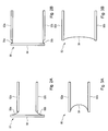
- FIGS. 1A are 1B are side views of a simplified version of a bellows synthetic jet 10 including flaps, 16a and 16b, in a first position and a second position, respectively, in accordance with some embodiments.
- a cavity 14 is formed between the two flaps 16a and 16b, a back wall 24 and two sidewalls (not shown). The sidewalls are discussed with in more detail with respect to FIGs. 2A, 2B , 2C and 2D.
- An aperture 20 from the cavity 14 allows for fluid to be alternately sucked into and ejected from the cavity 14.
- a cavity 14 can be formed between a single flap, a back wall, sidewalls and a stationary surface opposite the flap.
- the flap 16b can be replaced with a stationary surface.
- FIGs. 1A and 1B is for illustrative purposes and is not meant to be limiting.
- the flaps, 16a and 16b are attached to a hinge mechanisms 18a and 18b, respectively.
- one or more actuators can be coupled to each of the flaps.
- the actuators can be used to move the flaps toward each other as shown in 12 or away from one another as shown in 32.
- one or more actuators can be coupled to the flaps where the actuators drive the motion in both directions (i.e., the flaps towards each other and away from another).
- one or more actuators can be used to drive the motion in one direction and then some other mechanism can be used to provide a restoring force.
- a spring can be placed between flaps16a and 16b, which push the flaps apart after the actuators push the flaps together.
- the volume of the cavity 14 decreases, and a fluid, such as air, can be expelled from the cavity through aperture 20 as shown in 34.
- a fluid such as air
- vortices are ejected from the aperture 20, which interact with the fluid surrounding the aperture to form the synthetic jet.
- the flaps 16a and 16b can be moved at a high frequency.
- the flaps 16a and 16b may each be moved back in forth at a high frequency.
- the flaps can be driven at hundreds to thousands of cycles per second. However, this frequency range is but one example and is not meant to be limiting.
- the flaps can be moved in phase with one another, i.e., both flaps move together and apart at the same time at the same frequency.
- the two flaps can be moved at the same frequency but out of phase with one another or can be moved at different frequencies.
- the frequency at which the flaps operate can be varied during operation.
- a first frequency of one flap can be selected to match a structural resonance associated with the actuator and a second frequency can be selected to match an acoustic resonance associated with the actuator.
- a control system can be configured to vary each of the first and second frequencies as a function of time. For example, at a first time, both flaps can be driven at the acoustic resonance frequency and at a second time the first flap can be driven at the structural resonance frequency and the second flap can be driven at the acoustic resonance frequency.
- the structural resonance of the pumping flap can be coupled to acoustic resonance of the cavity.
- this coupling can provide a strong resonant amplification of an already mechanically amplified piezoceramic actuator.
- the acoustic pressure distribution 22 can vary from a max on the side of the cavity opposite the aperture 20 to a minimum near the aperture. This distribution is especially favorable for a flap that rotates about a hinge line near the pressure minimum so that the part of the flap 16a or 16b with the highest velocity and greatest range of motion is coincident with the part of the acoustic mode with the highest pressure.
- the rotating flap Since coupling between the structural resonance and the acoustic resonance is proportional to the integral of the out-of-plane motion of the structural mode and the collocated acoustic pressure respectively, the rotating flap increases coupling as compared to a uniform flap motion with the same average velocity. Thus, the motion of the flap is high where the pressure is high and low where the pressure is low.
- the axisymmetric shape of the disk prevents taking advantage of this phenomenon.
- the coupling effect found with the bellows design doesn't come into play.
- FIG. 1C is a top view of a flap 40 for a bellows synthetic jet, in accordance with some embodiments.
- the flap 40 includes a top side 42a, a bottom side 42b connected by sidewalls 44a and 44b.
- the flap 40 can be hinged alongside 42a or side 42b.
- the flap angle 46 associated with the sidewalls can be up to 90 degrees to provide a rectangular flap.
- the shape can cause the flow to converge into the nozzle (e.g., see aperture 20 in FIGs. 1A and 1B or aperture 56 in FIG. 1D ), which may improve the efficiency of the device.
- a hinge line can be provided and then a shape, such as a shape symmetric about a line perpendicular to the hinge line, can extend from the hinge line.
- the flap shapes each had a constant area.
- One characteristic length of the shapes is a maximum distance from the nozzle aperture. It was found that the acoustic resonance frequency can be primarily a function of the distance from the nozzle aperture to the back of the cavity. Further, it was found that some shapes with a smaller characteristic length and hence a higher acoustic frequency as compared to shapes of the same area with a larger characteristic length and larger acoustic frequency can achieve a lower structural resonance frequency, which is related to the time it takes the flap to cycle through it motion. A flap design with a higher structural resonant frequency can result in a more efficient generation of a synthetic jet.
- FIG. 1D is a front view 40 of a bellows synthetic jet including the jet nozzle aperture 52 and, in accordance with some embodiments.
- the nozzle aperture 52 is a rectangular slit with short sides 54a and 54b joined by long sides 56a and 56b.
- the height of the aperture can vary between sides 54a and 54b.
- the shape of the aperture 52 can include one or more curved portions.
- the aperture 52 can be a group of openings, such as a number of circular openings arranged in a line or some other pattern.
- the bellows synthetic jet includes a cavity where portions of the cavity are formed by one or more flaps.
- the sidewalls of the cavity adjacent to the one or more flaps can be configured to perform work or not perform on the fluid within the cavity. Two examples illustrating these configurations are described as follows with respect to FIGS. 2A, 2B, 3A and 3B .
- FIGs. 2A and 2B are front views of portions of a bellows synthetic jet 60 including a rigid side frame 64 and associated seals, such as 66a and 66b, in different actuation positions, in accordance with some embodiments.
- the bellows synthetic jet includes two flaps, 62a and 62b, which move towards and apart from one another to perform work on a fluid between the flaps. As described above, the two flaps, 62a and62b, can be hinged.
- a sidewall 64 which can be formed from a rigid or semi-rigid material, is located adjacent to the flaps, 62a and 62b. In one embodiment, the sidewall can be part of a structural frame used to provide structural support for the bellows synthetic jet 60.
- a sealing mechanism can be utilized to prevent fluid leakage at the interface between the sidewall 64 and the flaps, 62a and 62b.
- the sealing mechanism can be a flexible membrane, such as 66a and 66b.
- the sealing membranes, 66a and 66b can be coupled to the sidewall 64 along a length of the flaps 62a and 62b which extends to the hinge line. As the flaps, 62a and 62b, move towards and away from one another, the membranes, 66a and 66b, can stretch or contract to maintain the seals. In this configuration, the seals, 66a and 66b, do a minimal amount of work on the fluid in the cavity between the flaps, 62a and 62b.
- a bellows synthetic jet can be configured such that the sidewalls adjacent the one or more flaps perform some work on the fluid in the cavity.
- FIGs. 3A and 3B are front views of a portion of a bellows synthetic jet 80 including a flexible sidewall 84 in different actuation positions, in accordance with some embodiments. The two flaps, 82a and 82b, move closer and apart from one another as shown in FIGs. 3A and 3B .
- the two flaps are joined together via a flexible membrane 84.
- the flexible membrane 84 is configured to bow inwards as the two flaps, 82a and 82b, move towards one another. The bowing motion reduces a volume of the cavity between the flaps to perform work on the fluid in the cavity. The additional work performed by the sidewalls may increase the overall efficiency of the device.
- FIG. 4 is a side view of an actuator 106 and flap 102 configuration for a bellows synthetic jet 100.
- the flap 102 can be formed from a rigid lightweight material.
- the flap 102 has a length 114. The thickness of the flap 102 varies along the length 114.
- An actuator 106 is in contact with the flap at a height 110 and anchored to support structure 104.
- the actuator 106 is designed to expand and contract.
- the tip 116 of the flap 102 moves downward as the flap102 rotates around hinge mechanism 112.
- the actuator contracts the tip 116 moves upwards as the flap 102 rotates in the opposite direction around hinge mechanism 112.
- a flapping motion is generated as the actuator is repeatedly activated.
- the up and down motion of the tip 116 can be mechanically amplified according to the ratio of length 114 to the height 110.
- the expansion and contraction of the actuator 106 can occur at a high frequency, such as at a frequency between 200 and 2000 HZ.
- a synthetic jet may not form until some minimum frequency is reached.
- the actuator 106 can be formed from a piezoelectric material.
- the actuator 106 can be a piezoceramic stack actuator.
- piezoceramic stack actuator One advantage of piezoceramic stack actuator is it has a minimal amount of moving parts.
- other types of actuator can be utilized and the example of an actuator using a piezoelectric material is provided from the purposes of illustration only.
- FIG. 5A is perspective view of a bellows synthetic jet 200, in accordance with some embodiments.
- the bellows synthetic jet 200 includes to flap and actuator mechanisms which arranged opposite one another to form a cavity.
- the cavity includes an exit aperture 206.
- the sidewalls of the cavity are rigid and are not configured to perform work on the fluid within the cavity.
- the top upper flap 200 is visible.
- the upper flap 204 is configured to rotate around a hinge line 204 near aperture 206.
- the support structure for the flaps is anchored to base 208. When actuated, a tip of the flap moves towards and away from the base 208.
- FIG. 5B is a side view of a bellows synthetic jet 200, in accordance with some embodiments.
- the two flaps 202 and 210 are arranged opposite one another. Flap 202 is configured to rotate about an axis through point 214a and flap 210 is configured to rotate about an axis 214b.
- the two flaps, 202 and 210 move towards and away from one another.
- the two flaps are shown at a position where the tips are at a minimum distance from one another.
- the bottom surfaces of flaps 202 and 210 are proximately parallel to one another. From this position, flap 202 moves in direction 212a and flap 210 moves in direction 212b.
- the flaps can be configured to move past the parallel position to reach the minimum distance between the tips or stop and move apart before the parallel position is reached.
- FIG. 5C is a cross-sectional view of a bellows synthetic jet 200, in accordance with some embodiments.
- the flaps 202 and 210 are coupled to hinge mechanisms, 222a and 222b.
- the hinge mechanisms, 222a and 222b can be formed from a flexible material, such as a strip of metal. In other examples, more mechanically complex hinge mechanisms can be utilized.
- a strip of material is used as a hinge mechanism, the flaps 202 and 210 can be bonded to their respective hinge mechanisms. For example, depending on the materials for the flap and hinge, the flaps can be bonded using an adhesive, solder or some other bonding agent.
- a cavity 228 is formed between the two flaps in this position.
- the cavity 228 is in fluid communication with nozzle 226. Fluid outside of the bellows synthetic jet 200 can be drawn through the nozzle 226 into the cavity 228 when the flaps, 202 and 210, move away from one another. When the flaps, 202 and 210, move towards one another fluid in cavity 228 can enter nozzle 226 and exit through aperture 206 as shown in FIG. 5A .
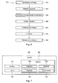
- aircraft manufacturing and service method 600 shown in FIG. 6 and an aircraft 630 shown in FIG. 7 will now be described to better illustrate various features of processes and systems presented herein.
- the aircraft may utilize embodiments of the bellow synthetic jet, such as for flow control over a wing.
- aircraft manufacturing and service method 600 may include specification and design 602 of aircraft 630 and material procurement 604.
- the production phase involves component and subassembly manufacturing 606 and system integration 608 of aircraft 630.
- aircraft 630 may go through certification and delivery 610 in order to be placed in service 612.
- routine maintenance and service 614 which may also include modification, reconfiguration, refurbishment, and so on). While the embodiments described herein relate generally to servicing of commercial aircraft, they may be practiced at other stages of the aircraft manufacturing and service method 600.
- Each of the processes of aircraft manufacturing and service method 600 may be performed or carried out by a system integrator, a third party, and/or an operator (e.g., a customer).
- a system integrator may include, without limitation, any number of aircraft manufacturers and major-system subcontractors
- a third party may include, for example, without limitation, any number of venders, subcontractors, and suppliers
- an operator may be an airline, leasing company, military entity, service organization, and so on.
- aircraft 630 produced by aircraft manufacturing and service method 600 may include airframe 632, interior 636, and multiple systems 634 and interior 636.
- systems 634 include one or more of propulsion system 638, electrical system 640, hydraulic system 642, and environmental system 644. Any number of other systems may be included in this example.
- propulsion system 638 the principles of the disclosure may be applied to other industries, such as the automotive industry.
- hydraulic system 642 the principles of the disclosure may be applied to other industries, such as the automotive industry.
- Apparatus and methods embodied herein may be employed during any one or more of the stages of aircraft manufacturing and service method 600.
- components or subassemblies corresponding to component and subassembly manufacturing 606 may be fabricated or manufactured in a manner similar to components or subassemblies produced while aircraft 630 is in service.
- one or more apparatus embodiments, method embodiments, or a combination thereof may be utilized during component and subassembly manufacturing 606 and system integration 608, for example, without limitation, by substantially expediting assembly of or reducing the cost of aircraft 630.
- one or more of apparatus embodiments, method embodiments, or a combination thereof may be utilized while aircraft 630 is in service, for example, without limitation, to maintenance and service 614 may be used during system integration 608 and/or maintenance and service 614 to determine whether parts may be connected and/or mated to each other.
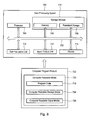
- data processing system 700 can be used to control operation of one or more bellows synthetic jets.
- Data processing system 700 may be used to implement one or more computers used in a controller or other components of various systems described above.
- data processing system 700 includes communications framework 702, which provides communications between processor unit 704, memory 706, persistent storage 708, communications unit 710, input/output (I/O) unit 712, and display 714.
- communications framework 702 may take the form of a bus system.
- Processor unit 704 serves to execute instructions for software that may be loaded into memory 706.
- Processor unit 704 may be a number of processors, a multi-processor core, or some other type of processor, depending on the particular implementation.
- Memory 706 and persistent storage 708 are examples of storage devices 716.
- a storage device is any piece of hardware that is capable of storing information, such as, for example, without limitation, data, program code in functional form, and/or other suitable information either on a temporary basis and/or a permanent basis.
- Storage devices 716 may also be referred to as computer readable storage devices in these illustrative examples.
- Memory 706, in these examples, may be, for example, a random access memory or any other suitable volatile or non-volatile storage device.
- Persistent storage 708 may take various forms, depending on the particular implementation. For example, persistent storage 708 may contain one or more components or devices.
- persistent storage 708 may be a hard drive, a flash memory, a rewritable optical disk, a rewritable magnetic tape, or some combination of the above.
- the media used by persistent storage 708 also may be removable.
- a removable hard drive may be used for persistent storage 708.
- Communications unit 710 in these illustrative examples, provides for communications with other data processing systems or devices.
- communications unit 710 is a network interface card.
- Input/output unit 712 allows for input and output of data with other devices that may be connected to data processing system 700.
- input/output unit 712 may provide a connection for user input through a keyboard, a mouse, and/or some other suitable input device. Further, input/output unit 712 may send output to a printer.
- Display 714 provides a mechanism to display information to a user.
- Instructions for the operating system, applications, and/or programs may be located in storage devices 716, which are in communication with processor unit 704 through communications framework 702.
- the processes of the different embodiments may be performed by processor unit 704 using computer-implemented instructions, which may be located in a memory, such as memory 706.
- program code computer usable program code
- computer readable program code that may be read and executed by a processor in processor unit 704.
- the program code in the different embodiments may be embodied on different physical or computer readable storage media, such as memory 706 or persistent storage 708.
- Program code 718 is located in a functional form on computer readable media 720 that is selectively removable and may be loaded onto or transferred to data processing system 700 for execution by processor unit 704.
- Program code 718 and computer readable media 720 form computer program product 722 in these illustrative examples.
- computer readable media 720 may be computer readable storage media 724 or computer readable signal media 726.
- computer readable storage media 724 is a physical or tangible storage device used to store program code 718 rather than a medium that propagates or transmits program code 718.
- program code 718 may be transferred to data processing system 700 using computer readable signal media 726.
- Computer readable signal media 726 may be, for example, a propagated data signal containing program code 718.
- Computer readable signal media 726 may be an electromagnetic signal, an optical signal, and/or any other suitable type of signal. These signals may be transmitted over communications links, such as wireless communications links, optical fiber cable, coaxial cable, a wire, and/or any other suitable type of communications link.
- the different components illustrated for data processing system 700 are not meant to provide architectural limitations to the manner in which different embodiments may be implemented.
- the different illustrative embodiments may be implemented in a data processing system including components in addition to and/or in place of those illustrated for data processing system 700.
- Other components shown in Figure 7 can be varied from the illustrative examples shown.
- the different embodiments may be implemented using any hardware device or system capable of running program code 718.
Applications Claiming Priority (1)
| Application Number | Priority Date | Filing Date | Title |
|---|---|---|---|
| US13/899,754 US9243622B2 (en) | 2013-05-22 | 2013-05-22 | Bellows synthetic jet |
Publications (2)
| Publication Number | Publication Date |
|---|---|
| EP2805880A1 true EP2805880A1 (fr) | 2014-11-26 |
| EP2805880B1 EP2805880B1 (fr) | 2018-04-04 |
Family
ID=50693536
Family Applications (1)
| Application Number | Title | Priority Date | Filing Date |
|---|---|---|---|
| EP14168234.4A Active EP2805880B1 (fr) | 2013-05-22 | 2014-05-14 | Jet synthétique à soufflet |
Country Status (4)
| Country | Link |
|---|---|
| US (1) | US9243622B2 (fr) |
| EP (1) | EP2805880B1 (fr) |
| CN (1) | CN104176236B (fr) |
| CA (1) | CA2849200C (fr) |
Families Citing this family (5)
| Publication number | Priority date | Publication date | Assignee | Title |
|---|---|---|---|---|
| US9803666B2 (en) | 2015-05-14 | 2017-10-31 | The Boeing Company | Piezoelectric actuators optimized for synthetic jet actuators |
| US10605280B2 (en) * | 2016-11-06 | 2020-03-31 | The Boeing Company | Phase tailoring for resonant flow devices |
| US11002221B2 (en) * | 2017-07-19 | 2021-05-11 | The Boeing Company | Acoustic cavity tailored synthetic jet |
| CN109669438B (zh) * | 2018-12-14 | 2020-07-21 | 北京东土科技股份有限公司 | 飞行器伺服弹性测试分析系统和介质 |
| JP2023508500A (ja) * | 2019-12-29 | 2023-03-02 | アクタシス インコーポレイテッド | アクティブフロー制御アクチュエータを使用した温度制御 |
Citations (3)
| Publication number | Priority date | Publication date | Assignee | Title |
|---|---|---|---|---|
| US5690165A (en) * | 1993-02-02 | 1997-11-25 | Ltg Lufttechnische Gmbh | Ventilation device for a space zone |
| US20080087771A1 (en) * | 2006-08-23 | 2008-04-17 | Lockheed Martin | High performance synthetic valve/pulsator |
| US20120170216A1 (en) * | 2011-01-04 | 2012-07-05 | General Electric Company | Synthetic jet packaging |
Family Cites Families (8)
| Publication number | Priority date | Publication date | Assignee | Title |
|---|---|---|---|---|
| FR1496152A (fr) * | 1966-06-20 | 1967-09-29 | Giravions Dorand | Tuyère pour aile d'avion ou pale d'hélicoptère soufflée |
| US6722581B2 (en) * | 2001-10-24 | 2004-04-20 | General Electric Company | Synthetic jet actuators |
| US8016244B2 (en) * | 2004-02-20 | 2011-09-13 | The Boeing Company | Active systems and methods for controlling an airfoil vortex |
| US20060196638A1 (en) * | 2004-07-07 | 2006-09-07 | Georgia Tech Research Corporation | System and method for thermal management using distributed synthetic jet actuators |
| JP4882639B2 (ja) * | 2006-09-29 | 2012-02-22 | ブラザー工業株式会社 | アクチュエータ、ポンプ、及び、光スキャナ |
| US8931518B2 (en) * | 2008-09-23 | 2015-01-13 | The Boeing Company | Shaping a fluid cavity of a flow control actuator for creation of desired waveform characteristics |
| WO2011077424A1 (fr) * | 2009-12-21 | 2011-06-30 | Ramot At Tel-Aviv University Ltd. | Générateur de tourbillon oscillatoire et ses applications |
| FR2968735B1 (fr) * | 2010-12-14 | 2014-03-14 | Onera Office National Detudes Et De Rech Aerospatiales | Micro-generateur fluidique de jets synthetiques. |
-
2013
- 2013-05-22 US US13/899,754 patent/US9243622B2/en active Active
-
2014
- 2014-04-17 CA CA2849200A patent/CA2849200C/fr active Active
- 2014-04-28 CN CN201410174708.9A patent/CN104176236B/zh active Active
- 2014-05-14 EP EP14168234.4A patent/EP2805880B1/fr active Active
Patent Citations (3)
| Publication number | Priority date | Publication date | Assignee | Title |
|---|---|---|---|---|
| US5690165A (en) * | 1993-02-02 | 1997-11-25 | Ltg Lufttechnische Gmbh | Ventilation device for a space zone |
| US20080087771A1 (en) * | 2006-08-23 | 2008-04-17 | Lockheed Martin | High performance synthetic valve/pulsator |
| US20120170216A1 (en) * | 2011-01-04 | 2012-07-05 | General Electric Company | Synthetic jet packaging |
Also Published As
| Publication number | Publication date |
|---|---|
| CN104176236A (zh) | 2014-12-03 |
| CN104176236B (zh) | 2018-07-31 |
| US20140348668A1 (en) | 2014-11-27 |
| CA2849200A1 (fr) | 2014-11-22 |
| EP2805880B1 (fr) | 2018-04-04 |
| CA2849200C (fr) | 2016-06-21 |
| US9243622B2 (en) | 2016-01-26 |
Similar Documents
| Publication | Publication Date | Title |
|---|---|---|
| EP2805880B1 (fr) | Jet synthétique à soufflet | |
| Cattafesta III et al. | Actuators for active flow control | |
| US20030075615A1 (en) | Synthetic jet actuators | |
| JP2018042453A (ja) | 圧電アクチュエータ及びこれを使用した小型流体制御装置 | |
| US20020081198A1 (en) | Jet actuators for aerodynamic surfaces | |
| TWI689664B (zh) | 致動氣體導流裝置 | |
| Zhang et al. | Active control for wall drag reduction: Methods, mechanisms and performance | |
| EP3431762B1 (fr) | Jet synthétique sur mesure à cavité acoustique | |
| US20180073527A1 (en) | Piezoelectric Actuators Optimized for Synthetic Jet Actuators | |
| Olivett et al. | Flow control and separation delay in morphing wing aircraft using traveling wave actuation | |
| US20200400136A1 (en) | Venturi Pump Systems And Methods To Use Same | |
| EP2873609B1 (fr) | Silencieux à jet synthétique | |
| US9422954B2 (en) | Piezoelectric driven oscillating surface | |
| JP6606142B2 (ja) | 流体制御装置の製造方法 | |
| Yee et al. | High-speed air microjet arrays produced using acoustic streaming for micro propulsion | |
| Rusovici et al. | A coupled field finite element modeling procedure for design of a synthetic-jet actuators | |
| Bailo et al. | Investigation of PVdF active diaphragms for synthetic jets | |
| Pandey et al. | Design and Simulation of Valveless PZT Micropump for Drug Delivery system | |
| Gilbert et al. | Actuator concepts and mechatronics | |
| Schueller et al. | Fluidic actuators for active flow control on airframe | |
| Lipowski et al. | Development of synthetic jet actuator array for vortex-flow generation | |
| JP2019044769A (ja) | 気体輸送装置 | |
| TWM553376U (zh) | 致動氣體導流裝置 | |
| CN110873681B (zh) | 具有微粒检测模块的行动装置 | |
| CN109424525B (zh) | 致动器 |
Legal Events
| Date | Code | Title | Description |
|---|---|---|---|
| PUAI | Public reference made under article 153(3) epc to a published international application that has entered the european phase |
Free format text: ORIGINAL CODE: 0009012 |
|
| 17P | Request for examination filed |
Effective date: 20140514 |
|
| AK | Designated contracting states |
Kind code of ref document: A1 Designated state(s): AL AT BE BG CH CY CZ DE DK EE ES FI FR GB GR HR HU IE IS IT LI LT LU LV MC MK MT NL NO PL PT RO RS SE SI SK SM TR |
|
| AX | Request for extension of the european patent |
Extension state: BA ME |
|
| R17P | Request for examination filed (corrected) |
Effective date: 20150526 |
|
| RBV | Designated contracting states (corrected) |
Designated state(s): AL AT BE BG CH CY CZ DE DK EE ES FI FR GB GR HR HU IE IS IT LI LT LU LV MC MK MT NL NO PL PT RO RS SE SI SK SM TR |
|
| 17Q | First examination report despatched |
Effective date: 20170105 |
|
| GRAP | Despatch of communication of intention to grant a patent |
Free format text: ORIGINAL CODE: EPIDOSNIGR1 |
|
| INTG | Intention to grant announced |
Effective date: 20171011 |
|
| GRAS | Grant fee paid |
Free format text: ORIGINAL CODE: EPIDOSNIGR3 |
|
| GRAA | (expected) grant |
Free format text: ORIGINAL CODE: 0009210 |
|
| AK | Designated contracting states |
Kind code of ref document: B1 Designated state(s): AL AT BE BG CH CY CZ DE DK EE ES FI FR GB GR HR HU IE IS IT LI LT LU LV MC MK MT NL NO PL PT RO RS SE SI SK SM TR |
|
| REG | Reference to a national code |
Ref country code: GB Ref legal event code: FG4D |
|
| REG | Reference to a national code |
Ref country code: CH Ref legal event code: EP |
|
| REG | Reference to a national code |
Ref country code: AT Ref legal event code: REF Ref document number: 985315 Country of ref document: AT Kind code of ref document: T Effective date: 20180415 |
|
| REG | Reference to a national code |
Ref country code: DE Ref legal event code: R096 Ref document number: 602014023203 Country of ref document: DE |
|
| REG | Reference to a national code |
Ref country code: IE Ref legal event code: FG4D |
|
| REG | Reference to a national code |
Ref country code: FR Ref legal event code: PLFP Year of fee payment: 5 |
|
| REG | Reference to a national code |
Ref country code: NL Ref legal event code: MP Effective date: 20180404 |
|
| REG | Reference to a national code |
Ref country code: LT Ref legal event code: MG4D |
|
| PG25 | Lapsed in a contracting state [announced via postgrant information from national office to epo] |
Ref country code: NL Free format text: LAPSE BECAUSE OF FAILURE TO SUBMIT A TRANSLATION OF THE DESCRIPTION OR TO PAY THE FEE WITHIN THE PRESCRIBED TIME-LIMIT Effective date: 20180404 |
|
| PG25 | Lapsed in a contracting state [announced via postgrant information from national office to epo] |
Ref country code: BG Free format text: LAPSE BECAUSE OF FAILURE TO SUBMIT A TRANSLATION OF THE DESCRIPTION OR TO PAY THE FEE WITHIN THE PRESCRIBED TIME-LIMIT Effective date: 20180704 Ref country code: NO Free format text: LAPSE BECAUSE OF FAILURE TO SUBMIT A TRANSLATION OF THE DESCRIPTION OR TO PAY THE FEE WITHIN THE PRESCRIBED TIME-LIMIT Effective date: 20180704 Ref country code: PL Free format text: LAPSE BECAUSE OF FAILURE TO SUBMIT A TRANSLATION OF THE DESCRIPTION OR TO PAY THE FEE WITHIN THE PRESCRIBED TIME-LIMIT Effective date: 20180404 Ref country code: ES Free format text: LAPSE BECAUSE OF FAILURE TO SUBMIT A TRANSLATION OF THE DESCRIPTION OR TO PAY THE FEE WITHIN THE PRESCRIBED TIME-LIMIT Effective date: 20180404 Ref country code: LT Free format text: LAPSE BECAUSE OF FAILURE TO SUBMIT A TRANSLATION OF THE DESCRIPTION OR TO PAY THE FEE WITHIN THE PRESCRIBED TIME-LIMIT Effective date: 20180404 Ref country code: SE Free format text: LAPSE BECAUSE OF FAILURE TO SUBMIT A TRANSLATION OF THE DESCRIPTION OR TO PAY THE FEE WITHIN THE PRESCRIBED TIME-LIMIT Effective date: 20180404 Ref country code: AL Free format text: LAPSE BECAUSE OF FAILURE TO SUBMIT A TRANSLATION OF THE DESCRIPTION OR TO PAY THE FEE WITHIN THE PRESCRIBED TIME-LIMIT Effective date: 20180404 Ref country code: FI Free format text: LAPSE BECAUSE OF FAILURE TO SUBMIT A TRANSLATION OF THE DESCRIPTION OR TO PAY THE FEE WITHIN THE PRESCRIBED TIME-LIMIT Effective date: 20180404 |
|
| PG25 | Lapsed in a contracting state [announced via postgrant information from national office to epo] |
Ref country code: HR Free format text: LAPSE BECAUSE OF FAILURE TO SUBMIT A TRANSLATION OF THE DESCRIPTION OR TO PAY THE FEE WITHIN THE PRESCRIBED TIME-LIMIT Effective date: 20180404 Ref country code: LV Free format text: LAPSE BECAUSE OF FAILURE TO SUBMIT A TRANSLATION OF THE DESCRIPTION OR TO PAY THE FEE WITHIN THE PRESCRIBED TIME-LIMIT Effective date: 20180404 Ref country code: RS Free format text: LAPSE BECAUSE OF FAILURE TO SUBMIT A TRANSLATION OF THE DESCRIPTION OR TO PAY THE FEE WITHIN THE PRESCRIBED TIME-LIMIT Effective date: 20180404 Ref country code: GR Free format text: LAPSE BECAUSE OF FAILURE TO SUBMIT A TRANSLATION OF THE DESCRIPTION OR TO PAY THE FEE WITHIN THE PRESCRIBED TIME-LIMIT Effective date: 20180705 |
|
| REG | Reference to a national code |
Ref country code: CH Ref legal event code: PL |
|
| REG | Reference to a national code |
Ref country code: AT Ref legal event code: MK05 Ref document number: 985315 Country of ref document: AT Kind code of ref document: T Effective date: 20180404 |
|
| PG25 | Lapsed in a contracting state [announced via postgrant information from national office to epo] |
Ref country code: PT Free format text: LAPSE BECAUSE OF FAILURE TO SUBMIT A TRANSLATION OF THE DESCRIPTION OR TO PAY THE FEE WITHIN THE PRESCRIBED TIME-LIMIT Effective date: 20180806 |
|
| REG | Reference to a national code |
Ref country code: DE Ref legal event code: R097 Ref document number: 602014023203 Country of ref document: DE |
|
| REG | Reference to a national code |
Ref country code: BE Ref legal event code: MM Effective date: 20180531 |
|
| PG25 | Lapsed in a contracting state [announced via postgrant information from national office to epo] |
Ref country code: EE Free format text: LAPSE BECAUSE OF FAILURE TO SUBMIT A TRANSLATION OF THE DESCRIPTION OR TO PAY THE FEE WITHIN THE PRESCRIBED TIME-LIMIT Effective date: 20180404 Ref country code: DK Free format text: LAPSE BECAUSE OF FAILURE TO SUBMIT A TRANSLATION OF THE DESCRIPTION OR TO PAY THE FEE WITHIN THE PRESCRIBED TIME-LIMIT Effective date: 20180404 Ref country code: MC Free format text: LAPSE BECAUSE OF FAILURE TO SUBMIT A TRANSLATION OF THE DESCRIPTION OR TO PAY THE FEE WITHIN THE PRESCRIBED TIME-LIMIT Effective date: 20180404 Ref country code: SK Free format text: LAPSE BECAUSE OF FAILURE TO SUBMIT A TRANSLATION OF THE DESCRIPTION OR TO PAY THE FEE WITHIN THE PRESCRIBED TIME-LIMIT Effective date: 20180404 Ref country code: RO Free format text: LAPSE BECAUSE OF FAILURE TO SUBMIT A TRANSLATION OF THE DESCRIPTION OR TO PAY THE FEE WITHIN THE PRESCRIBED TIME-LIMIT Effective date: 20180404 Ref country code: AT Free format text: LAPSE BECAUSE OF FAILURE TO SUBMIT A TRANSLATION OF THE DESCRIPTION OR TO PAY THE FEE WITHIN THE PRESCRIBED TIME-LIMIT Effective date: 20180404 Ref country code: CZ Free format text: LAPSE BECAUSE OF FAILURE TO SUBMIT A TRANSLATION OF THE DESCRIPTION OR TO PAY THE FEE WITHIN THE PRESCRIBED TIME-LIMIT Effective date: 20180404 |
|
| PLBE | No opposition filed within time limit |
Free format text: ORIGINAL CODE: 0009261 |
|
| STAA | Information on the status of an ep patent application or granted ep patent |
Free format text: STATUS: NO OPPOSITION FILED WITHIN TIME LIMIT |
|
| REG | Reference to a national code |
Ref country code: IE Ref legal event code: MM4A |
|
| PG25 | Lapsed in a contracting state [announced via postgrant information from national office to epo] |
Ref country code: CH Free format text: LAPSE BECAUSE OF NON-PAYMENT OF DUE FEES Effective date: 20180531 Ref country code: LI Free format text: LAPSE BECAUSE OF NON-PAYMENT OF DUE FEES Effective date: 20180531 Ref country code: SM Free format text: LAPSE BECAUSE OF FAILURE TO SUBMIT A TRANSLATION OF THE DESCRIPTION OR TO PAY THE FEE WITHIN THE PRESCRIBED TIME-LIMIT Effective date: 20180404 Ref country code: IT Free format text: LAPSE BECAUSE OF FAILURE TO SUBMIT A TRANSLATION OF THE DESCRIPTION OR TO PAY THE FEE WITHIN THE PRESCRIBED TIME-LIMIT Effective date: 20180404 |
|
| 26N | No opposition filed |
Effective date: 20190107 |
|
| PG25 | Lapsed in a contracting state [announced via postgrant information from national office to epo] |
Ref country code: LU Free format text: LAPSE BECAUSE OF NON-PAYMENT OF DUE FEES Effective date: 20180514 |
|
| PG25 | Lapsed in a contracting state [announced via postgrant information from national office to epo] |
Ref country code: IE Free format text: LAPSE BECAUSE OF NON-PAYMENT OF DUE FEES Effective date: 20180514 |
|
| PG25 | Lapsed in a contracting state [announced via postgrant information from national office to epo] |
Ref country code: BE Free format text: LAPSE BECAUSE OF NON-PAYMENT OF DUE FEES Effective date: 20180531 Ref country code: SI Free format text: LAPSE BECAUSE OF FAILURE TO SUBMIT A TRANSLATION OF THE DESCRIPTION OR TO PAY THE FEE WITHIN THE PRESCRIBED TIME-LIMIT Effective date: 20180404 |
|
| PG25 | Lapsed in a contracting state [announced via postgrant information from national office to epo] |
Ref country code: MT Free format text: LAPSE BECAUSE OF NON-PAYMENT OF DUE FEES Effective date: 20180514 |
|
| PG25 | Lapsed in a contracting state [announced via postgrant information from national office to epo] |
Ref country code: TR Free format text: LAPSE BECAUSE OF FAILURE TO SUBMIT A TRANSLATION OF THE DESCRIPTION OR TO PAY THE FEE WITHIN THE PRESCRIBED TIME-LIMIT Effective date: 20180404 |
|
| PG25 | Lapsed in a contracting state [announced via postgrant information from national office to epo] |
Ref country code: HU Free format text: LAPSE BECAUSE OF FAILURE TO SUBMIT A TRANSLATION OF THE DESCRIPTION OR TO PAY THE FEE WITHIN THE PRESCRIBED TIME-LIMIT; INVALID AB INITIO Effective date: 20140514 |
|
| PG25 | Lapsed in a contracting state [announced via postgrant information from national office to epo] |
Ref country code: CY Free format text: LAPSE BECAUSE OF FAILURE TO SUBMIT A TRANSLATION OF THE DESCRIPTION OR TO PAY THE FEE WITHIN THE PRESCRIBED TIME-LIMIT Effective date: 20180404 Ref country code: MK Free format text: LAPSE BECAUSE OF NON-PAYMENT OF DUE FEES Effective date: 20180404 |
|
| PG25 | Lapsed in a contracting state [announced via postgrant information from national office to epo] |
Ref country code: IS Free format text: LAPSE BECAUSE OF FAILURE TO SUBMIT A TRANSLATION OF THE DESCRIPTION OR TO PAY THE FEE WITHIN THE PRESCRIBED TIME-LIMIT Effective date: 20180804 |
|
| P01 | Opt-out of the competence of the unified patent court (upc) registered |
Effective date: 20230516 |
|
| PGFP | Annual fee paid to national office [announced via postgrant information from national office to epo] |
Ref country code: FR Payment date: 20230525 Year of fee payment: 10 Ref country code: DE Payment date: 20230530 Year of fee payment: 10 |
|
| PGFP | Annual fee paid to national office [announced via postgrant information from national office to epo] |
Ref country code: GB Payment date: 20230529 Year of fee payment: 10 |