EP2805811B1 - Platte mit gefaltetem Kern - Google Patents
Platte mit gefaltetem Kern Download PDFInfo
- Publication number
- EP2805811B1 EP2805811B1 EP14169177.4A EP14169177A EP2805811B1 EP 2805811 B1 EP2805811 B1 EP 2805811B1 EP 14169177 A EP14169177 A EP 14169177A EP 2805811 B1 EP2805811 B1 EP 2805811B1
- Authority
- EP
- European Patent Office
- Prior art keywords
- folded core
- peak
- core
- peaks
- folded
- Prior art date
- Legal status (The legal status is an assumption and is not a legal conclusion. Google has not performed a legal analysis and makes no representation as to the accuracy of the status listed.)
- Active
Links
Images





Classifications
-
- B—PERFORMING OPERATIONS; TRANSPORTING
- B32—LAYERED PRODUCTS
- B32B—LAYERED PRODUCTS, i.e. PRODUCTS BUILT-UP OF STRATA OF FLAT OR NON-FLAT, e.g. CELLULAR OR HONEYCOMB, FORM
- B32B3/00—Layered products comprising a layer with external or internal discontinuities or unevennesses, or a layer of non-planar shape; Layered products comprising a layer having particular features of form
- B32B3/10—Layered products comprising a layer with external or internal discontinuities or unevennesses, or a layer of non-planar shape; Layered products comprising a layer having particular features of form characterised by a discontinuous layer, i.e. formed of separate pieces of material
- B32B3/12—Layered products comprising a layer with external or internal discontinuities or unevennesses, or a layer of non-planar shape; Layered products comprising a layer having particular features of form characterised by a discontinuous layer, i.e. formed of separate pieces of material characterised by a layer of regularly- arranged cells, e.g. a honeycomb structure
-
- B—PERFORMING OPERATIONS; TRANSPORTING
- B32—LAYERED PRODUCTS
- B32B—LAYERED PRODUCTS, i.e. PRODUCTS BUILT-UP OF STRATA OF FLAT OR NON-FLAT, e.g. CELLULAR OR HONEYCOMB, FORM
- B32B3/00—Layered products comprising a layer with external or internal discontinuities or unevennesses, or a layer of non-planar shape; Layered products comprising a layer having particular features of form
- B32B3/26—Layered products comprising a layer with external or internal discontinuities or unevennesses, or a layer of non-planar shape; Layered products comprising a layer having particular features of form characterised by a particular shape of the outline of the cross-section of a continuous layer; characterised by a layer with cavities or internal voids ; characterised by an apertured layer
- B32B3/28—Layered products comprising a layer with external or internal discontinuities or unevennesses, or a layer of non-planar shape; Layered products comprising a layer having particular features of form characterised by a particular shape of the outline of the cross-section of a continuous layer; characterised by a layer with cavities or internal voids ; characterised by an apertured layer characterised by a layer comprising a deformed thin sheet, i.e. the layer having its entire thickness deformed out of the plane, e.g. corrugated, crumpled
-
- B—PERFORMING OPERATIONS; TRANSPORTING
- B32—LAYERED PRODUCTS
- B32B—LAYERED PRODUCTS, i.e. PRODUCTS BUILT-UP OF STRATA OF FLAT OR NON-FLAT, e.g. CELLULAR OR HONEYCOMB, FORM
- B32B7/00—Layered products characterised by the relation between layers; Layered products characterised by the relative orientation of features between layers, or by the relative values of a measurable parameter between layers, i.e. products comprising layers having different physical, chemical or physicochemical properties; Layered products characterised by the interconnection of layers
- B32B7/04—Interconnection of layers
- B32B7/12—Interconnection of layers using interposed adhesives or interposed materials with bonding properties
-
- B—PERFORMING OPERATIONS; TRANSPORTING
- B64—AIRCRAFT; AVIATION; COSMONAUTICS
- B64C—AEROPLANES; HELICOPTERS
- B64C1/00—Fuselages; Constructional features common to fuselages, wings, stabilising surfaces or the like
-
- B—PERFORMING OPERATIONS; TRANSPORTING
- B64—AIRCRAFT; AVIATION; COSMONAUTICS
- B64C—AEROPLANES; HELICOPTERS
- B64C1/00—Fuselages; Constructional features common to fuselages, wings, stabilising surfaces or the like
- B64C1/38—Constructions adapted to reduce effects of aerodynamic or other external heating
-
- B—PERFORMING OPERATIONS; TRANSPORTING
- B64—AIRCRAFT; AVIATION; COSMONAUTICS
- B64C—AEROPLANES; HELICOPTERS
- B64C3/00—Wings
- B64C3/26—Construction, shape, or attachment of separate skins, e.g. panels
-
- B—PERFORMING OPERATIONS; TRANSPORTING
- B32—LAYERED PRODUCTS
- B32B—LAYERED PRODUCTS, i.e. PRODUCTS BUILT-UP OF STRATA OF FLAT OR NON-FLAT, e.g. CELLULAR OR HONEYCOMB, FORM
- B32B2250/00—Layers arrangement
- B32B2250/40—Symmetrical or sandwich layers, e.g. ABA, ABCBA, ABCCBA
-
- B—PERFORMING OPERATIONS; TRANSPORTING
- B32—LAYERED PRODUCTS
- B32B—LAYERED PRODUCTS, i.e. PRODUCTS BUILT-UP OF STRATA OF FLAT OR NON-FLAT, e.g. CELLULAR OR HONEYCOMB, FORM
- B32B2605/00—Vehicles
- B32B2605/18—Aircraft
-
- B—PERFORMING OPERATIONS; TRANSPORTING
- B32—LAYERED PRODUCTS
- B32B—LAYERED PRODUCTS, i.e. PRODUCTS BUILT-UP OF STRATA OF FLAT OR NON-FLAT, e.g. CELLULAR OR HONEYCOMB, FORM
- B32B2607/00—Walls, panels
-
- B—PERFORMING OPERATIONS; TRANSPORTING
- B32—LAYERED PRODUCTS
- B32B—LAYERED PRODUCTS, i.e. PRODUCTS BUILT-UP OF STRATA OF FLAT OR NON-FLAT, e.g. CELLULAR OR HONEYCOMB, FORM
- B32B37/00—Methods or apparatus for laminating, e.g. by curing or by ultrasonic bonding
- B32B37/12—Methods or apparatus for laminating, e.g. by curing or by ultrasonic bonding characterised by using adhesives
-
- Y—GENERAL TAGGING OF NEW TECHNOLOGICAL DEVELOPMENTS; GENERAL TAGGING OF CROSS-SECTIONAL TECHNOLOGIES SPANNING OVER SEVERAL SECTIONS OF THE IPC; TECHNICAL SUBJECTS COVERED BY FORMER USPC CROSS-REFERENCE ART COLLECTIONS [XRACs] AND DIGESTS
- Y02—TECHNOLOGIES OR APPLICATIONS FOR MITIGATION OR ADAPTATION AGAINST CLIMATE CHANGE
- Y02T—CLIMATE CHANGE MITIGATION TECHNOLOGIES RELATED TO TRANSPORTATION
- Y02T50/00—Aeronautics or air transport
- Y02T50/40—Weight reduction
-
- Y—GENERAL TAGGING OF NEW TECHNOLOGICAL DEVELOPMENTS; GENERAL TAGGING OF CROSS-SECTIONAL TECHNOLOGIES SPANNING OVER SEVERAL SECTIONS OF THE IPC; TECHNICAL SUBJECTS COVERED BY FORMER USPC CROSS-REFERENCE ART COLLECTIONS [XRACs] AND DIGESTS
- Y10—TECHNICAL SUBJECTS COVERED BY FORMER USPC
- Y10T—TECHNICAL SUBJECTS COVERED BY FORMER US CLASSIFICATION
- Y10T156/00—Adhesive bonding and miscellaneous chemical manufacture
- Y10T156/10—Methods of surface bonding and/or assembly therefor
-
- Y—GENERAL TAGGING OF NEW TECHNOLOGICAL DEVELOPMENTS; GENERAL TAGGING OF CROSS-SECTIONAL TECHNOLOGIES SPANNING OVER SEVERAL SECTIONS OF THE IPC; TECHNICAL SUBJECTS COVERED BY FORMER USPC CROSS-REFERENCE ART COLLECTIONS [XRACs] AND DIGESTS
- Y10—TECHNICAL SUBJECTS COVERED BY FORMER USPC
- Y10T—TECHNICAL SUBJECTS COVERED BY FORMER US CLASSIFICATION
- Y10T428/00—Stock material or miscellaneous articles
- Y10T428/24—Structurally defined web or sheet [e.g., overall dimension, etc.]
- Y10T428/24628—Nonplanar uniform thickness material
- Y10T428/24669—Aligned or parallel nonplanarities
Definitions
- honeycomb panels typically consist of a honeycomb core sandwiched between two face sheets.
- Honeycomb panels can be relatively lightweight, yet rigid, when compared to other types of panels, lending themselves to multiple uses in an aircraft. Examples of uses include the exterior skin panels of the aircraft, flooring, and the sidewalls of an aircraft.
- US5443779 relates to a method of production of a composite corrugated body wherein vertically extending ridges and grooves are formed alternately in a sheet material to form corrugate lines that meander in a plane to form a corrugated body and wherein a flat liner is adhered to at least one of the opposite faces of the corrugated body, and to a method of formation of corrugating rollers for use in production of such composite corrugated body.
- WO2005058593 relates to a sandwich panel with light core from corrugated sheet material in the form of zigzag crimp.
- honeycomb cores can suffer from various material issues. For example, honeycomb cores can be prone to moisture ingression issues. Moisture can seep into cracks and crevices of the honeycomb panels, but may not be removed because a honeycomb pattern may not facilitate much, if any, airflow. The remaining moisture may collect underneath the face sheets, which over time, may cause the face sheets to peel off.
- Honeycomb cores may also require a relatively large amount of adhesive to be applied to properly join the honeycomb core to the face sheets.
- a relatively large amount of shear force may be applied to a face sheet. The shear force may be transferred to the interface between the face sheet and the honeycomb core. Delamination at the face sheet and the honeycomb core may occur unless a proper amount of adhesive is applied to the honeycomb core.
- a panel for use in an aircraft may include a top face sheet, a bottom face sheet, and a folded core bonded to the top face sheet and the bottom face sheet.
- the folded core may be characterized by a corrugated zigzag pattern having a plurality of non-vertical faces ending in a plurality of peaks and a plurality of valleys.
- the plurality of peaks comprises a generally planar peak having a sharp bend at a zenith, thus providing a partial angular peak.
- a folded core for use in an aircraft may include one or more peaks having a one or more ridges and one or more valleys.
- the one or more peaks and the one or more valleys may be formed in a corrugated zigzag pattern.
- a method of making an aircraft panel may include providing a top face sheet, providing a bottom face sheet and providing a folded core characterized by a corrugated zigzag pattern.
- the folded core may include a plurality of peaks and a plurality of valleys.
- the plurality of peaks comprises a generally planar peak having a sharp bend at a zenith, thus providing a partial angular peak.
- the method may further include applying an adhesive to a top surface of the folded core, applying the adhesive to a bottom surface of the folded core, and curing the adhesive to form an integral panel.
- a stacked core may include one or more folded cores.
- the folded cores may include peaks with one or more ridges, valleys, and non-vertical faces extending between the peaks and the valleys.
- the peaks and the valleys may be formed in a corrugated zigzag pattern.
- the folded cores may include complementary features to allow a first folded core to be stacked on a second folded core.
- a folded core panel for use in an aircraft panel.
- a folded core panel according to various concepts described herein can provide various peaks upon which a bond may be formed to bond the folded core to face sheets to form the panel.
- the peaks can provide a bonding surface area greater than the bonding surface area of comparable, conventional core designs. The bonding surface area may help to reduce the amount of bonding agent necessary to sufficiently bond the core to the face sheets.
- the peaks of the folded core panel are designed to present a flat, or nearly flat, surface area to an adhesive.
- the flat profile can provide an increased surface area onto which an adhesive may bond the folded core to the face sheet.
- a greater bonding surface area may distribute shear forces, as well as other forces, to a greater area of the core bonded to a face sheet. This may reduce the amount of shear force applied to any one specific location of the core. Because of this, in some configurations, a reduction in the amount of adhesive necessary may be realized over similar, conventional core designs.
- a folded core according to further concepts provided herein may also provide for valleys that provide space sufficient to allow air to flow through the core. In some configurations, this may minimize or eliminate moisture ingress.
- Conventional honeycomb panels have cores with honeycomb-shaped structures that are tightly packed in a vertical configuration, as illustrated in FIG. 1 .
- a honeycomb panel 100 of conventional design consists of a honeycomb core 102 sandwiched between a top face sheet 104 and a bottom face sheet 106.
- the honeycomb core 102 is typically bonded to the top face sheet 104 and the bottom face sheet 106 through the use of an adhesive (not shown).
- the honeycomb core 102 consists of several honeycomb structures, such as the honeycomb structures 108 and 110.
- the honeycomb structures 108 and 110 are tightly packed together, that is, the shape and design of the honeycomb structures 108 and 110 allow for the edges of the structures to be flush with adjacent honeycomb structures. While providing for the desired structural rigidity and strength, the tight packing of the honeycomb structures reduces or eliminations any airflow paths through the honeycomb core 102. In some implementations, the ability to remove moisture that may collect in the honeycomb core 102 is prevented by the tight packing of the honeycomb structures 108 and 110.
- the moisture may collect and affect the bond between the honeycomb core 102 and the face sheets 104 and 106, possibly causing the delamination of a portion of the face sheets 104 and 106.
- the delamination of the face sheets 104 or 106 can cause structural failure and present safety issues.
- conventional honeycomb cores may not provide adequate bonding area.
- One method of increasing the bond may be through the use of an excess amount of adhesive. While providing a bond sufficient to handle the various stresses applied to the honeycomb panel 100, the additional adhesive can increase the weight of the honeycomb panel 100 beyond an intended or desired amount.
- the bonding surface area such as the surface area 112
- the honeycomb core 102 is preferably hollow with generally even wall thickness along the length of the honeycomb structures that form the honeycomb core 102.
- the honeycomb structures 108 and 110 may need to be manufactured with increased wall thickness.
- the honeycomb structures 108 and 110 may be manufactured with variable wall thickness, with the greater thickness at the surface area 112 and the thinner wall thickness near a central point of the honeycomb structures 108 and 110.
- Either method can significantly increase the complexity of the manufacturing process, thus increasing cost.
- Increasing the surface area 112 may require specialized manufacturing equipment, resulting in increases in cost and time to make the honeycomb core 102.
- the additional materials associated with the increased surface area can translate to a heavier honeycomb core 102, possibly negating the benefits of using the honeycomb panel 100.
- a folded core according to various concepts described herein uses a folded design to increase the surface area for bonding, while, in some configurations, provides an airflow passageway to help remove moisture.
- the folded core 202 can be constructed of one or more layers of composite material, plastic, metal.
- the folded core 202 may be characterized as having a corrugated zigzag pattern.
- corrugated includes a surface having parallel peaks and valleys.
- zigzag includes a pattern having lines characterized by angular turns. It should be understood that the designation of a structure as a "peak” or a “valley” may depend on the orientation of the folded core 202. For example, if the folded core 202 is rotated upside-down, the peaks may resemble valleys. In a similar manner, the valleys may resemble and provide similar functionality to peaks in a different orientation of the folded core 202. Accordingly, the presently disclosed subject matter is not limited to any particular orientation of the peaks and valleys described herein, as the identification and functionality may depend on the orientation of the folded core.
- the folded core 202 can be formed by folding or forming a material in a V-shaped pattern having a series of peaks 204 and valleys 206 at distal ends of faces 205 that are non-vertical.
- the folded core 202 can be formed using a mandrel (not shown) or other forming apparatus.
- the folded core 202 may be formed by laying down plies of composite matrix-forming material into a mandrel and curing the material into the shape of the folded core 202.
- the folded core 202 may be a plastic material, such as thermoplastic or thermoset. The plastic material may be extruded or formed into the shape of the folded core 202 using convention plastic-forming techniques.
- the folded core 202 may be a metal or metal-alloy.
- the material may be folded or cast using conventional metal forming techniques.
- the folded core 202 is a single piece of material.
- single includes uncut. The concepts and technologies described herein are not limited to any particular material or any particular method for forming the material.
- peaks 204 are defined by ridges 208 that present a surface area for bonding the folded core 202 to a face sheet using a bonding agent.
- a bonding agent includes a chemical, physical, metallic or other mechanism in which a bond may be formed.
- a bonding agent may be an adhesive, a weld, a rivet.
- Various aspects of the folded core 202 may be modified to provide various characteristics. Some examples of characteristics include, but are not limited to, bonding strength to a face sheet, the ability of the folded core 202 to withstand outside forces, the weight of the folded core 202, and moisture removal capabilities.
- One example of a modification that may be made to the folded core 202 is the surface profile of the ridges 208.
- the surface profile of the ridges 208 may be configured to provide various benefits, including, but not limited to, increasing or decreasing the bond between the folded core 202 and a face sheet.
- Some examples of surface profiles include, but are not limited to, an angular, flat, or rounded profile, or combinations thereof. Each profile type may provide various benefits. For example, an angular surface profile may provide a smaller surface area for adhesion when compared to other types of profiles, but may use less material, resulting in possible weight savings.
- the flat surface profile may provide a greater surface area for bonding than an angular surface profile and may also present a flatter surface to absorb an impact or outside force, but may use more material than the angular surface profile.
- the rounded surface profile may provide a middle ground between the benefits of an angular surface profile and the flat surface profile.
- the ridges 208 are illustrated as having an angular profile. Examples of some surface profiles for the ridges 208 are illustrated in further detail in FIG. 3 below.
- the folded core 202 may be configured based on the desired characteristics of the folded core 202.
- the V-shaped pattern of the peaks 204 may be changed.
- a peak 204A and a peak 204B are shown having an angular displacement, illustrated as a peak angle ⁇ , that forms the V-shaped pattern.
- the peak angle ⁇ may be set to optimize the folded core 202 for the particular use of the folded core 202.
- the peak angle ⁇ may be relatively small to increase the surface area of the ridges 208 in a particular area, which may increase the surface area available for bonding the folded core 202 to a face sheet.
- the peak angle ⁇ may also be relatively large to decrease the amount of material used to form the folded core 202.
- a slope may be defined as the gradient of the faces 205.
- the face 205A may have a face slope ⁇ measured by the ratio of the altitude change to the horizontal distance between a peak 204C and a valley 206A.
- the face slope ⁇ may be set at a particular gradient to provide various benefits for load transfer, airflow, and the like.
- a relatively large face slope may provide a better compressive load transfer path than a relatively smaller face slope.
- a relatively smaller face slope may provide a better shear load transfer path than a relatively larger face slope.
- the folded core 202 may include a channel 210 from point A to point B along the axis AB defined by the peaks 204, the faces 205 and the valleys 206.
- the channel 210 may provide a way to allow moisture to exit the folded core 202.
- the channel 210 may be large enough to provide sufficient space to reduce the concentration of the moisture at any one location in the channel 210. Reducing the concentration of moisture at any one point may reduce the likelihood of moisture damaging the bond between the folded core 202 and its facing sheets.
- FIG. 3 is a side cross-sectional view of a portion of the folded core 202 showing peaks 204D-204F, faces 205D-205E, and valleys 206D-206E.
- the peak 204D has a generally angular surface profile
- the peak 204E has a generally flat surface profile
- the peak 204F has a generally round surface profile.
- the peak 204D may provide a cost and time savings benefit over the peaks 204E or 204F.
- the singular fold at the apex of the peak 204D may not provide an equivalent surface area for a bonding agent when compared to the peaks 204E and 204F.
- the flat portion of the peak 204E may present a greater surface area upon which a bonding agent may be affixed than the apex of the peak 204D, thus providing a stronger bond in some configurations.
- the rounded shape of the peak 204F may also provide an increased surface area upon which a bonding agent may be applied when compared to the peak 204D.
- the peaks 204E and 204F may utilize more material in their construction than the peak 204D, thus increasing the weight of the folded core 202.
- the choice of peak profile may depend on the design considerations for a particular application. In some implementations, different peaks 204 in the same folded core 202 may have different surface profiles to optimize the peaks 204 for the use at a particular location in the folded core 202.
- the face 205D has a face slope ⁇ , defined by an angle ⁇
- the face 205E has a face slope ⁇ ', defined by an angle ⁇ '.
- the face slope ⁇ ' is smaller than the face slope ⁇ .
- the angle ⁇ and the angle ⁇ ' may range from 10 degrees to 80 degrees. In some further examples, the angle ⁇ and the angle ⁇ ' may range from 30 degrees to 60 degrees.
- the upper and lower limits of the angle ⁇ and the angle ⁇ ' may vary depending on design considerations. Having a larger slope can better handle a compressive force C acting in a generally normal path to the height of the peak 204D.
- a large slope such as the face slope ⁇ , may better transfer the compressive force C because the compressive force C is transferred in a generally normal direction to the face slope ⁇ , reducing the amount of torque applied to radius bend 320.
- the face slope ⁇ may not be particularly well-suited to handle a shear force S acting in a generally lateral direction along the length of the peak 204D.
- the steeper slope of the face slope ⁇ causes a greater degree of torque to be generated at the radius bend 320 as compared to a smaller slope.
- the peak 204E may be better suited to handle the shear force S than the peak 204D.
- the smaller slope provided by the slope ⁇ ' places the structure generally more in-line with the shear force S, thus reducing the generation of torque at the radius bend 322.
- the structure of the peak 204E is not generally in-line with the compressive force C.
- the peak 204E may not be able to handle the compressive force C as well as the peak 204D.
- the peaks 204 may have different face slopes in the same folded core 202 to provide various benefits at particular locations.
- the folded core 202 may have more than one face slope to optimize the folded core 202 for a force-handling requirement at a particular location.
- the folded core 202 may use a peak having a profile similar to the peak 204D, which may provide weight reduction capabilities.
- the folded core 202 may use a peak having a profile similar to the peak 204E, which may provide increased adhesive capabilities but may suffer from increased weight when compared to the peak 204D.
- the folded core 202 may use various combinations of the peaks 204D-204F optimize the folded 202 depending on the specific conditions at the location of the peak.
- the face slope of the folded core 202 may also be configured to provide for a certain degree of air transfer.
- a channel 310 may have a certain volume and channel profile provided the peaks 204D-204E and the valley 206D
- a channel 312 may have a certain volume and channel profile provided the peaks 204E-204F and the valley 206E.
- Different profiles may provide different moisture movement capabilities.
- the face slopes may be adjusted based on desired airflow capabilities, as well as force handling capabilities if that is an additional factor. These and other capabilities may be provided by configuring other aspects of the folded core 202.
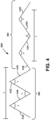
- FIG. 4 is a top-down view of a ridge 208A of the folded core 202.
- the peak 204 is shown having a peak angle ⁇ in a section 402 and a peak angle ⁇ ' in a section 404.
- the peak angle ⁇ is a narrow peak angle and the peak angle ⁇ ' is a wide peak angle.
- a narrow peak angle includes a peak angle equal to or less than 90 degrees. In some examples, a narrow peak angle may range from 20 degrees to 90 degrees.
- the lower limit of the peak angle ⁇ may be limited by the amount of material used in the composite structure as well as weight considerations. The ability to bend layers of material into relatively narrow angles without damage to the materials decreases as the amount of material increases.
- a "wide peak angle" includes a peak angle greater than 90 degrees. In some examples, a wide peak angle may range from greater than 90 degrees to 150 degrees. In some implementations, the upper limit of the peak angle ⁇ may be limited by a reduction in the advantages attainted by a folded core. As the peak angle ⁇ increases, the ridge 208A increasingly resembles a straight line, reducing the bonding surface area and the amount of material available for force absorption. Decreasing the peak angle can increase the amount of surface area to which the folded core 202 may be bonded to face sheets by increasing the surface area of the ridge 208A per a given length.
- the lengths 410A-410H are areas on the ridge 208A to which an adhesive or other bonding agent may be applied to bond the folded core 202 to a face sheet. Increasing the number of lengths can provide an increased bond between the folded core 202 and a face sheet at a particular location.
- the portion of the ridge 208A provided by the peak angle ⁇ may include lengths 410A-410D within a transverse length L of the ridge 208A.
- the portion of the ridge 208A having the peak angle ⁇ ' may include lengths 410F and 410G but only portions of length 410E and 410H within the same transverse length L of the ridge 208A.
- the portion of the ridge 208A provided by the peak angle ⁇ provides more area along the transverse length L due to the increased number of the lengths 410, as compared to the portion of the ridge 208A having the peak angle ⁇ .
- the greater number of lengths may help to increase the strength of the bond between the folded core 202 and a face sheet. But, the increased number of lengths may also impact the weight of the material for a given length. All other factors being equal, increasing the amount of material in a given transverse length L can increase the weight of the folded core 202.
- the folded core 202 may also be configured with peaks having more than one peak angle. For example, in areas in which a relatively strong bond strength is desired, the folded core 202 may have a peak with the narrow peak angle ⁇ . In areas in which the strength of the bond may not be a factor as much as the weight savings, the folded core 202 may have a peak with the portion provided by the wide peak angle ⁇ .
- FIGS. 5 and 6 provide examples of further configurations of folded core panels.
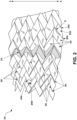
- FIG. 5 a perspective view of a folded core 502 is illustrated.
- the folded core 502 has peaks 504, which are identified with a star, " ".
- the peaks 504 provide a bonding surface to which the folded core 502 may be bonded to a face sheet.
- the peaks 504 may also act as an initial force transfer interface between a load applied to the peaks 504 and some other structure in an aircraft.
- the peaks 504 have a generally planar shape when compared to the peaks 204 of FIG. 2 .
- the planar shape may provide various benefits over other shapes.
- a planar shape may provide for a better bond strength when compared to an angular shape.
- the greater surface area of the peaks 504 may present a relatively larger interface to which chemical bonds may be formed with the adhesive, thus possibly increasing the bonding strength for a given amount of adhesive.
- Increasing the bonds between the peaks 504 and an adhesive can also help to reduce the amount of adhesive necessary to create a bond of a certain strength. If more bonds are available for adhesion, less adhesive may be needed to create a bond having a strength similar to bonds between more angular peaks, such as the peaks 204 of FIG. 2 , and a face sheet.
- the increased surface area of the peaks 504 in relation to other configurations for peaks may help to distribute a force to a greater area than what may be found in the other peak designs.
- the distribution of forces may help reduce the impact of a force at any one particular location of the peaks 504. For example, a force of one pound-force applied to a surface having an area of one square inch translates to a pressure of one pound per square inch, whereas, the same one pound-force applied to a surface having an area of one hundred square inches translates to a pressure of one pound per one hundred square inches.
- the force of the second scenario is distributed to a greater surface area, i.e. one hundred square inches rather than one square inch, thus minimizing the effect of the same force at any one location on the peaks 504.
- peaks 504 may have a lighter design, needing only to account for a smaller pound-force per square inch than a comparable peak, such as the peaks 204 of FIG. 2 , which are angular in nature and, therefore, may not disperse a force in a similar manner.
- the folded core 502 also includes valleys 506, identified in FIG. 5 with a circle, " ".
- the valleys 506 may be configured in a manner similar to the peaks 504 to provide similar structural benefits when used to bond the folded core 502 to a folded sheet. Further, the configuration of the valleys 504 may help to provide an airflow channel 510.
- the airflow channel 510 may allow moisture that enters the folded core 502 to exit the folded core 502 along the airflow channel 510.
- Moisture may enter the folded core 502 in various ways.
- defects in the face sheets may allow ingress points through which water or other liquids may enter the folded core 502.
- the folded core 504 may be constructed of composite materials that are cured.
- the various materials in the composite structure may use resins or other liquids in the manufacturing or curing process. Unless the liquids are extracted during the curing phase, the liquid may remain in the folded core 502. Over a period of time, the moisture may degrade the materials in the folded core 502. For example, some adhesives may degrade over time when exposed to moisture. This degradation of the adhesive can reduce the strength of the bond between the folded core 502 and a face sheet, allowing the face sheet to delaminate and separate from the folded core 502. The depths of the valleys 506 may affect the geometry, and thus performance, of the airflow channel 510.
- FIG. 6 is an illustration of a folded core 602 that may use features associated with a generally planar folded core peak along with features associated with an angular folded core peak. Shown in FIG. 6 are peaks 604 and valleys 606 that form the folded core 602. As discussed previously, a generally flat surface on a peak may provide certain benefits over a generally angular peak, with the same being true in the reverse.
- a generally planar peak surface may increase the amount of area available for adhesion while also distribution forces over a greater area, possibly making a folded core using the generally planar peak strong than comparable folded cores. But, the generally planar peak surface may use more material, thus possibly increasing the weight of the folded core.
- a folded core using a generally angular peak surface may reduce the amount of material as well as may simplify construction, but may not have similar performance characteristics as generally planar peak surfaces with regard to bonding strength or force distribution.
- the folded core 602 of FIG. 6 has a structure that provides some benefits of both types of peak surfaces.
- peak 604A has an angular structure, which has a sharp bend at zenith 608, thus providing for at least a partial angular peak.
- peak 604A has planar surfaces 610.
- the planar surfaces 610 can present a generally planar surface to which an adhesive may be applied, thus providing a stronger bond in some configurations. Therefore, in some configurations, the folded core 602 may provide some benefits relating to a generally planar peak surface as well as a generally angular peak surface.
- FIGS. 7A-7C are side, cross-sectional views illustrating surface profiles of peaks in a folded core panel configured to receive complementary peaks of another folded core panel in a stacked folded core design.
- a folded core panel may be bonded to another folded core panel instead of a face sheet.
- the peaks may have a shape configured to receive an opposing peak for bonding.
- the peaks of one folded core may have a shape configured to receive a valley from another folded core. Having peaks with various complementary shapes may provide certain benefits in some implementations. For example, the peaks provide a certain amount of surface area for bonding.
- the complementary peaks may have a shape that provides some degree of structural rigidity.
- FIG. 7A is a side, cross-sectional view illustrating one exemplary configuration of complementary peaks. Illustrated is a portion of cores 702A1 and 702A2.
- the cores 702A1 and 702A2 include peaks 704A1 and 704A2, respectively.
- the peaks 704A1 and 704A2 have a generally flat surface profile.
- the peaks 704A1 and 704A2 may provide various benefits.
- the generally flat surface profile may be relatively easy to manufacture because of the absence of specialized or detailed features.
- the generally flat surface profile of the peaks 704A1 and 704A2 may provide an increased amount of surface available for bonding when compared to peaks having a generally angular profile.
- the configuration illustrated in FIG. 7A may be termed sparse stacking.
- the configuration may be termed sparse stacking because, when stacked, the folded cores do not abut against each other except for at interface location 720, which is the location at which the cores 702A1 and 702A2 are bonded to each other. The remaining portions of the cores 702A1 and 702A2 are not abutted against each other, providing for a relatively sparse amount of core per a given volume.
- FIGS. 8A-8C below, provide exemplary configurations of dense stacking.
- FIG. 7B is a side, cross-sectional view illustrating an alternate surface profile. Illustrated is a portion of cores 702B1 and 702B2.
- the cores 702B1 and 702B2 include peaks 704B1 and 704B2, respectively.
- the peaks 704B1 and 704B2 have a generally serrated surface profile.
- the peaks 704B1 and 704B2 may provide various benefits.
- the generally serrated surface profile may provide an increased surface area for bonding over the generally flat surface profile of FIG. 7A .
- the generally serrated surface profile may provide a mechanical benefit whereby lateral movement of the peaks 704B1 and 704B2 with respect to each other may be reduced or impeded.
- FIG. 7C is a side, cross-sectional view illustrating an alternate surface profile. Illustrated is a portion of core 702C1 and 702C2.
- the cores 702C1 and 702C2 include peaks 704C1 and 704C2, respectively.
- the peak 704C 1 has a generally convex surface profile and the peak 704C2 has a generally convex surface profile.
- the peaks 704C1 and 704C2 may provide various benefits.
- the complementary convex/concave surface profile may provide an increased surface area for bonding over the surface profile illustrated in FIG. 7A .
- the complementary convex/concave surface profile may provide for alignment during construction of the cores 702C1 and 702C2.
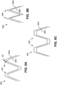
- FIGS. 8A-8C are side, cross-sectional views illustrating surface profiles of cores having complementary features that facilitate the stacking of folded cores on each other.
- a particular thickness of a folded core it may be preferable to build the folded core using successive layers of folded cores placed on each other.
- the successive stacking of the folded cores may be required if the core's thickness makes manufacturing relatively difficult.
- the areas in the folds may be prone to defects that are undetectable if the folded core is a single, unitary piece.
- the same thickness may be achievable if several, thinner folded cores are stacked on each other, with the resulting thickness being the desired thickness.
- the stacking of multiple folded cores to create a final folded core structure may have additional benefits. For example, it may be desirable for the final folded core structure to perform various functions at different levels. There may be several "strengthening" folded cores that are designed to provide a structural function. There may also be one or more cores that provide electrical functions, such as the conduction of electricity. In lieu of building a folded core from a single, unitary construction method, special-purposed folded core layers may be stacked on each other to provide the functionality desired. In some configurations, the folded cores in a folded core stack may use complementary features to provide both alignment capabilities as well as provide the structural benefits desired in a folded core.
- FIG. 8A is a side, cross-sectional view illustrating one configuration for complementary features for a stacked, folded core.
- a stacked core 802A includes a core 802A1 and a core 802A2.
- the cores 802A1 and 802A2 may be folded cores constructed in accordance with various configurations described herein. Further, the cores 802A1 and 802A2 may be formed from different materials or may have other differences.
- the core 802A1 may be a reinforcing core formed from relatively strong materials that are designed to provide structural support to the stacked core 802A.
- the core 802A2 may be an electrical core designed to conduct electricity, such as from lightning strikes.
- the core 802A1 or the core 802A2 may be an environmental core designed to be resistance to various environmental conditions that may damage other cores in the stacked core 802A. As illustrated in FIG. 8A , the cores 802A1 and 802A2 have peaks 804A that are rounded to form a generally convex surface profile.
- FIG. 8A also illustrates a dense stacking configuration.
- the folded cores forming the stacks illustrated in FIG. 8A abut each other along a significant portion of their length.
- the abutting of the cores can provide for a structure that may reduce voids or air pockets formed from a stacking operation, which may occur in the sparse stacking illustrated in FIGS. 7A-7C .
- dense stacking may be provided by abutting an inner surface 822 of the core 802A2 with an outer surface 824 of the core 802A1.
- the peaks of one folded core may lie in at least a portion of the valleys of a complementary, abutting folded core.
- the abutment may include a bonding agent or adhesive between the core 802A1 and the core 802A2 to bond the core 802A1 to the core 802A2.
- FIG. 8B is a side, cross-sectional view illustrating an alternate peak profile for a stacked core 802B.
- the stacked core 802B is formed from cores 802B1 and 802B2, which may be folded cores having various design configurations.
- the peaks 804B of the cores 802B1 and 802B2 are generally triangular in nature.
- FIG. 8C is a side, cross-sectional view illustrating a further alternate peak profile for a stacked core 802C.
- the stacked core 802C is formed from cores 802C1 and 802C2, which may be folded cores having various design configurations.
- the peaks 804C of the cores 802C1 and 802C2 have a generally planar surface profile.
- routine 900 for making an aircraft panel is provided herein. Unless otherwise indicated, it should be appreciated that more or fewer operations may be performed than shown in the figures and described herein. Additionally, unless otherwise indicated, these operations may also be performed in a different order than those described herein.
- the routine 900 starts at operation 902, where the top face sheet 104 and the bottom face sheet 106 are provided.
- the top face sheet 104 and the bottom face sheet 106 may be constructed from various materials, the present disclosure of which is not limited to any particular type.
- the routine 900 proceeds to operation 904, where the folded core 202 with the peaks 204 is provided.
- the peaks 204 may have an angular, flat or rounded profile. The present disclosure, however, it not limited to any profile.
- the folded core 202 may also include the valleys 206.
- the folded core 202 is a single piece of material that is folded in a corrugated zigzag pattern. In some configurations, no cuts are made to the material forming the folded core 202 during the folding process of the folded core 202.
- the generally flat surface profile of the peaks 204 and the valleys 206 can provide an improved bond between the folded core 202 and the face sheets 104 and 106.
- the routine 900 proceeds to operations 906 and 908, where an adhesive is applied between a top surface of the folded core 202 and a bottom surface of the top face sheet 104, and, an adhesive is applied between a bottom surface of the folded core 202 and a top surface of the bottom face sheet 106.
- the adhesive may be applied in various ways, of which the concepts described herein are not limited to any particular way.
- the adhesive can be applied initially only to the surfaces of the folded core 202, the surfaces of the top sheet 104 and the bottom sheet 106, or both.
- the routine 900 proceeds to operation 910, where the adhesive is cured to form an integral panel for use in an aircraft.
- integral includes a single unit. It should be understood that the concepts and technologies described herein are not limited to any particular adhesive or curing method, as any appropriate adhesive and method may be used. Thereafter, the routine 900 ends.
- a panel for use in an aircraft comprising:
- the plurality of peaks comprises a narrow peak angle.
- non-vertical faces comprise a plurality of face slopes.
- a peak of the plurality of peaks comprises an angular surface profile.
- a peak of the plurality of peaks comprises a round surface profile.
- the panel further comprising an airflow channel for removing moisture.
- the airflow channel is formed by the plurality of valleys.
- the folded core comprises a composite matrix.
- a folded core for use in an aircraft comprising:
- a first ridge of the plurality of ridges comprise a narrow peak angle
- a second ridge of the plurality of ridges further comprise a wide peak angle.
- a peak of the plurality of peaks comprises an angular surface profile or a round surface profile.
- the folded core further comprising a second folded core comprising a plurality of second peaks having shapes to receive at least a portion of the peaks.
- the shapes comprise a flat surface profile, a serrated surface profile or a convex/concave surface profile.
- the folded core is a single piece of material.
- the folded core comprises a composite matrix.
- a method of making an aircraft panel comprising:
- the generally flat surface profile comprises a narrow peak angle and a wide peak angle.
- a peak of the plurality of peaks comprises an angular surface profile, a round surface profile or a flat surface profile.
- the method further comprising an airflow channel formed by the plurality of valleys for removing moisture.
- a stacked core comprising: a plurality of folded cores comprising:
- the plurality of folded cores are sparse stacked.
- a peak of the first folded core is shaped to be complementary to a peak of the second folded core.
- the peak of the first folded core and the peak of the second folded core comprise a flat surface profile, a serrated surface profile, or a convex/concave surface profile.
- the plurality of folded cores are dense stacked.
- the stacked core further comprising a bonding agent to bond the first core to the second core.
- the first folded core provides a different function than the second folded core.
- the first folded core provides structural support to the stacked core, conducts electricity, or resists environmental conditions.
Landscapes
- Engineering & Computer Science (AREA)
- Mechanical Engineering (AREA)
- Aviation & Aerospace Engineering (AREA)
- Physics & Mathematics (AREA)
- Fluid Mechanics (AREA)
- Laminated Bodies (AREA)
Claims (13)
- Platte zur Verwendung in einem Luftfahrzeug, umfassend:ein oberseitiges Blech (104);ein unterseitiges Blech (106); undeinen ersten gefalteten Kern (202), der an das oberseitige Blech und das unterseitige Blech gebunden ist, wobei der erste gefaltete Kern durch ein wellenförmiges Zickzackmuster einer Mehrzahl von Erhöhungen (208) mit einer Mehrzahl von ersten Spitzen (204), einer Mehrzahl von Vertiefungen (206) und einer Mehrzahl von nicht vertikalen Flächen (205), die sich zwischen der Mehrzahl von ersten Spitzen und der Mehrzahl von Vertiefungen erstrecken, gekennzeichnet ist;wobei die Mehrzahl von ersten Spitzen jeder Erhöhung (208) eine im Allgemeinen planare Spitze (610) mit einer scharfen Biegung an einem Scheitelpunkt (608) umfasst, wodurch eine teilweise abgewinkelte Spitze bereitgestellt ist; wobei jede der Mehrzahl von Erhöhungen (208) ein im Allgemeinen flaches Oberflächenprofil mit einer Mehrzahl von ersten Spitzen (204), einschließlich einer Spitze mit einem schmalen Spitzenwinkel und einer Spitze mit einem breiten Spitzenwinkel, umfasst, und wobei ein schmaler Spitzenwinkel kleiner als oder gleich 90 Grad ist und ein breiter Spitzenwinkel größer als 90 Grad ist.
- Platte nach Anspruch 1, wobei die nicht vertikalen Flächen (205) eine Mehrzahl von Flächenneigungen umfassen.
- Platte nach einem der vorhergehenden Ansprüche, ferner umfassend einen Luftströmungskanal (510) zum Abführen von Feuchtigkeit.
- Platte nach Anspruch 3, wobei der Luftströmungskanal (510) von der Mehrzahl von Vertiefungen (206) gebildet ist.
- Platte nach einem der vorhergehenden Ansprüche, wobei der erste gefaltete Kern (202) eine Verbundmatrix umfasst.
- Platte nach einem der vorhergehenden Ansprüche, ferner umfassend einen zweiten gefalteten Kern (202), der eine Mehrzahl von zweiten Spitzen (204) umfasst, wobei eine Spitze des ersten gefalteten Kerns (202) so geformt ist, dass sie komplementär zu einer Spitze des zweiten gefalteten Kerns (202) ist, um zu ermöglichen, dass der erste gefaltete Kern auf den zweiten gefalteten Kern gestapelt wird.
- Platte nach Anspruch 6, wobei die Spitze des ersten gefalteten Kerns (202) und die Spitze des zweiten gefalteten Kerns (202) ein flaches Oberflächenprofil, ein gezacktes Oberflächenprofil oder ein konvexes/konkaves Oberflächenprofil umfassen.
- Platte nach einem der Ansprüche 1 bis 5, ferner umfassend einen zweiten gefalteten Kern (202), der eine Mehrzahl von zweiten Spitzen (204) umfasst, wobei eine Innenfläche des ersten gefalteten Kerns (202) auf einer Außenfläche des zweiten gefalteten Kerns aufliegt.
- Platte nach Anspruch 8, wobei das Auflager ein Bindemittel oder einen Klebstoff zwischen dem ersten gefalteten Kern (202) und dem zweiten gefalteten Kern (202) zum Binden des ersten gefalteten Kerns an den zweiten gefalteten Kern umfassen kann.
- Platte nach Anspruch 8 oder 9, wobei der erste gefaltete Kern (202) und der zweite gefaltete Kern (202) jeweils eines einer strukturellen und einer elektrischen Funktion bereitstellen.
- Platte nach einem der Ansprüche 6 bis 10, wobei der erste gefaltete Kern (202) ein einzelnes Materialstück ist und der zweite gefaltete Kern (202) ein einzelnes Materialstück ist.
- Verfahren zum Herstellen einer Luftfahrzeugplatte, umfassend:Bereitstellen eines oberseitigen Blechs (104);Bereitstellen eines unterseitigen Blechs (106);Bereitstellen eines gefalteten Kerns (202), der durch ein wellenförmiges Zickzackmuster einer Mehrzahl von Erhöhungen (208A) gekennzeichnet ist, umfassend;eine Mehrzahl von ersten Spitzen (204), undeine Mehrzahl von Vertiefungen (206),wobei die Mehrzahl von ersten Spitzen jeder Erhöhung (208A) eine im Allgemeinen planare Spitze (610) mit einer scharfen Biegung an einem Scheitelpunkt (608) umfasst,wodurch eine teilweise abgewinkelte Spitze bereitgestellt wird;Auftragen eines Klebstoffs auf eine obere Fläche des gefalteten Kerns;Auftragen des Klebstoffs auf eine untere Fläche des gefalteten Kerns; undAushärten des Klebstoffs, um eine integrale Platte zu bilden, wobei jede der Mehrzahl von Erhöhungen (208A) ein im Allgemeinen flaches Oberflächenprofil mit einer Mehrzahl von ersten Spitzen (204), einschließlich einer Spitze mit einem schmalen Spitzenwinkel und einer Spitze mit einem breiten Spitzenwinkel, umfasst,wobei ein schmaler Spitzenwinkel kleiner als oder gleich 90 Grad ist und ein breiter Spitzenwinkel größer als 90 Grad ist.
- Verfahren nach Anspruch 12, ferner umfassend einen Luftströmungskanal (510), der von der Mehrzahl von Vertiefungen (206) zum Abführen von Feuchtigkeit gebildet wird.
Applications Claiming Priority (1)
| Application Number | Priority Date | Filing Date | Title |
|---|---|---|---|
| US13/899,116 US20140349082A1 (en) | 2013-05-21 | 2013-05-21 | Folded Core Panel |
Publications (2)
| Publication Number | Publication Date |
|---|---|
| EP2805811A1 EP2805811A1 (de) | 2014-11-26 |
| EP2805811B1 true EP2805811B1 (de) | 2024-04-10 |
Family
ID=50732076
Family Applications (1)
| Application Number | Title | Priority Date | Filing Date |
|---|---|---|---|
| EP14169177.4A Active EP2805811B1 (de) | 2013-05-21 | 2014-05-20 | Platte mit gefaltetem Kern |
Country Status (9)
| Country | Link |
|---|---|
| US (1) | US20140349082A1 (de) |
| EP (1) | EP2805811B1 (de) |
| JP (1) | JP6461487B2 (de) |
| KR (1) | KR102154875B1 (de) |
| CN (1) | CN104175624B (de) |
| AU (1) | AU2014201426C1 (de) |
| BR (1) | BR102014012191B1 (de) |
| CA (1) | CA2847357C (de) |
| RU (1) | RU2673938C2 (de) |
Families Citing this family (28)
| Publication number | Priority date | Publication date | Assignee | Title |
|---|---|---|---|---|
| US9284726B2 (en) * | 2014-04-04 | 2016-03-15 | The Boeing Company | Pyramid waffle core structure and method of fabrication |
| US9592918B2 (en) | 2014-06-23 | 2017-03-14 | Rohr, Inc. | Acoustic liner |
| WO2017017149A1 (de) * | 2015-07-27 | 2017-02-02 | Karsten Pietsch | Einlagiger faltkern |
| US9764818B2 (en) | 2016-02-10 | 2017-09-19 | Rohr, Inc. | Structural, cellular core with corrugated support walls |
| US9761216B2 (en) | 2016-02-10 | 2017-09-12 | Rohr, Inc. | Acoustic panel with angled corrugated core structures |
| US9978354B2 (en) | 2016-04-15 | 2018-05-22 | Rohr, Inc. | Acoustic panel with vertical stiffeners |
| US9704467B1 (en) | 2016-04-15 | 2017-07-11 | Rohr, Inc. | Acoustic panel with corrugated baffles and septums |
| USD840551S1 (en) * | 2016-09-09 | 2019-02-12 | Arktura Llc | Architectural fixture |
| US10414481B2 (en) | 2017-02-14 | 2019-09-17 | Rohr, Inc. | Method for forming a structural panel |
| US10525636B2 (en) | 2017-06-19 | 2020-01-07 | Rohr, Inc. | Process for forming a fiber-reinforced composite structure |
| US10695986B2 (en) | 2017-08-22 | 2020-06-30 | Rohr, Inc. | Method for forming a structural panel |
| US10906659B2 (en) | 2018-04-03 | 2021-02-02 | Rohr, Inc. | Structured panel with structural reinforcement(s) |
| WO2020020587A1 (en) * | 2018-07-24 | 2020-01-30 | Low & Bonar Germany Gmbh & Co. Kg | Folded core structure and process for providing a folded core structure |
| US11242822B2 (en) | 2018-12-14 | 2022-02-08 | Rohr, Inc. | Structured panel with multi-panel structure(s) |
| US11398214B2 (en) | 2018-12-14 | 2022-07-26 | Rohr, Inc. | Forming a structured panel with one or more structural reinforcements |
| US11572850B2 (en) | 2019-06-04 | 2023-02-07 | Rohr, Inc. | Acoustic panel with one or more structural stiffeners |
| US12275520B2 (en) * | 2020-02-11 | 2025-04-15 | The Boeing Company | Liquid-diverting panel assemblies |
| US12269574B2 (en) | 2020-02-11 | 2025-04-08 | The Boeing Company | Methods for forming liquid flow paths on a surface of a structure |
| US11965465B2 (en) | 2020-12-22 | 2024-04-23 | Rohr, Inc. | Acoustic panel with multiple layer corrugated core |
| US11715450B2 (en) | 2020-12-22 | 2023-08-01 | Rohr, Inc. | Acoustic panel core cell with funnel shaped septum |
| US11618511B2 (en) | 2021-01-12 | 2023-04-04 | Honda Motor Co., Ltd. | Surface pattern for a vehicle |
| CN113478083B (zh) * | 2021-07-23 | 2023-03-14 | 马鞍山安达泰克科技有限公司 | 蜂窝芯材 |
| US11869472B2 (en) | 2021-08-02 | 2024-01-09 | Rohr, Inc. | Acoustic panel with reconfigurable chamber constrictions |
| EP4206448B1 (de) | 2022-01-04 | 2025-07-09 | Rohr, Inc. | Mehrkernige akustikplatte für ein flugzeugantriebssystem |
| US12163472B2 (en) | 2022-09-02 | 2024-12-10 | Rohr, Inc. | Engine exhaust nozzle with acoustic attenuation |
| US20250214712A1 (en) * | 2023-12-27 | 2025-07-03 | Rohr, Inc. | Acoustic panel for an aircraft propulsion system |
| US20250214713A1 (en) * | 2023-12-27 | 2025-07-03 | Rohr, Inc. | Acoustic panel for an aircraft propulsion system |
| EP4644231A1 (de) * | 2024-05-02 | 2025-11-05 | Airbus (S.A.S.) | Flugzeugstrukturbauteil mit einem als wärmetauscher ausgebildeten faltkern-sandwichelement |
Citations (1)
| Publication number | Priority date | Publication date | Assignee | Title |
|---|---|---|---|---|
| US5443779A (en) * | 1990-11-06 | 1995-08-22 | Ichikawa; Hiroo | Method of production of reinforced composite corrugated body and method of formation of corrugating rollers for use therein |
Family Cites Families (14)
| Publication number | Priority date | Publication date | Assignee | Title |
|---|---|---|---|---|
| FR1304146A (fr) * | 1961-08-09 | 1962-09-21 | Nouveaux matériaux délimités sur l'une au moins de leurs faces par une configuration du type des structures chevronnées développables, et procédés pour leur fabrication | |
| JPS58160130U (ja) * | 1982-04-20 | 1983-10-25 | 豊田紡織株式会社 | 軽量紙製成形品 |
| JPS6262744A (ja) * | 1985-09-13 | 1987-03-19 | 市川 博夫 | 折曲型複合コルゲ−ト体とその製造方法 |
| JPS62184848A (ja) * | 1986-02-10 | 1987-08-13 | 市川 博夫 | 強化複合コルゲ−ト体およびその製造方法 |
| US5028474A (en) * | 1989-07-25 | 1991-07-02 | Czaplicki Ronald M | Cellular core structure providing gridlike bearing surfaces on opposing parallel planes of the formed core |
| JP2000064499A (ja) * | 1998-08-26 | 2000-02-29 | Eriiteku Kk | 双曲放物線面の構造パネル |
| ATE431206T1 (de) * | 2003-11-20 | 2009-05-15 | Otkrytoe Aktsionernoe Obschest | Verfahren zur herstellung von sandwichplatten mit zickzackförmigem, gewelltem kern |
| DE60320465T2 (de) * | 2003-12-17 | 2009-05-07 | Airbus S.A.S. | Sandwichplatte |
| RU2265552C2 (ru) * | 2003-12-17 | 2005-12-10 | Открытое акционерное общество "Казанский научно-исследовательский институт авиационной технологии" | Многослойная панель |
| RU2352726C1 (ru) * | 2007-10-30 | 2009-04-20 | Казанский государственный технический университет им. А.Н. Туполева | Многослойная панель и способ ее изготовления |
| WO2009108712A2 (en) * | 2008-02-26 | 2009-09-03 | Klaus Stadthagen-Gonzalez | Structural element |
| DE102008019070B3 (de) * | 2008-04-15 | 2009-11-26 | Airbus Deutschland Gmbh | Verfahren zur Herstellung eines beidseitig mit Deckschichten versehenen Kernverbundes |
| DE102008019065B4 (de) * | 2008-04-15 | 2011-06-16 | Airbus Operations Gmbh | Verfahren zur Herstellung eines beidseitig mit Deckschichten versehenen Kernverbundes sowie Kernverbund |
| US8292227B2 (en) * | 2008-07-12 | 2012-10-23 | The Boeing Company | Aircraft wings having continuously tailored structural strength |
-
2013
- 2013-05-21 US US13/899,116 patent/US20140349082A1/en not_active Abandoned
-
2014
- 2014-03-12 AU AU2014201426A patent/AU2014201426C1/en active Active
- 2014-03-19 CA CA2847357A patent/CA2847357C/en active Active
- 2014-04-17 KR KR1020140045821A patent/KR102154875B1/ko active Active
- 2014-05-19 CN CN201410211151.1A patent/CN104175624B/zh active Active
- 2014-05-19 JP JP2014103633A patent/JP6461487B2/ja active Active
- 2014-05-19 RU RU2014119995A patent/RU2673938C2/ru active
- 2014-05-20 EP EP14169177.4A patent/EP2805811B1/de active Active
- 2014-05-20 BR BR102014012191-9A patent/BR102014012191B1/pt active IP Right Grant
Patent Citations (1)
| Publication number | Priority date | Publication date | Assignee | Title |
|---|---|---|---|---|
| US5443779A (en) * | 1990-11-06 | 1995-08-22 | Ichikawa; Hiroo | Method of production of reinforced composite corrugated body and method of formation of corrugating rollers for use therein |
Also Published As
| Publication number | Publication date |
|---|---|
| US20140349082A1 (en) | 2014-11-27 |
| CA2847357A1 (en) | 2014-11-21 |
| RU2673938C2 (ru) | 2018-12-03 |
| KR102154875B1 (ko) | 2020-09-11 |
| CN104175624A (zh) | 2014-12-03 |
| CN104175624B (zh) | 2018-10-30 |
| AU2014201426A1 (en) | 2014-12-11 |
| AU2014201426C1 (en) | 2018-06-28 |
| RU2014119995A (ru) | 2015-11-27 |
| AU2014201426B2 (en) | 2017-12-21 |
| EP2805811A1 (de) | 2014-11-26 |
| BR102014012191A2 (pt) | 2015-01-13 |
| JP6461487B2 (ja) | 2019-01-30 |
| KR20140136866A (ko) | 2014-12-01 |
| CA2847357C (en) | 2019-04-23 |
| JP2014227171A (ja) | 2014-12-08 |
| BR102014012191B1 (pt) | 2022-03-22 |
Similar Documents
| Publication | Publication Date | Title |
|---|---|---|
| CA2847357C (en) | Folded core panel | |
| US7541085B2 (en) | Flexible construction element with large bonding surface area and method of manufacture | |
| US10232528B2 (en) | Wind turbine blades | |
| US12083777B2 (en) | Honeycomb, in particular deformable honeycomb, for lightweight components, corresponding production method, and sandwich component | |
| CN101835548B (zh) | 面板结构 | |
| CN103547438B (zh) | 用于复合桁条的高容量拉脱的层叠条形件 | |
| NL1031768C2 (nl) | Hoogbelastbare sandwichstructuur, alsmede werkwijzen voor het vervaardigen daarvan. | |
| US20140004299A1 (en) | Cellular structure for double curvature panel | |
| US3642566A (en) | Quasi-isotropic sandwich core | |
| EP3134257B1 (de) | Platte aus laminaten und verfahren zur herstellung davon | |
| JP2020512222A (ja) | アルミハニカムコアの製造方法及び装置 | |
| EP1474293B1 (de) | Verfahren zur herstellung von zellularen strukturkernen geeignet zur verwendung von holz | |
| US20140170374A1 (en) | Core of Sheet Structural Material and Assembly Process | |
| CN107635761A (zh) | 用于生产具有不可展开形状的夹层金属部件的改进的方法 | |
| EP1379379B1 (de) | Verbesserte sandwich-bauelemente | |
| CN110114206A (zh) | 用于形成加强复合部件的方法 | |
| WO2019214408A1 (zh) | 芯材及其制作方法、复合材料 | |
| CN208085134U (zh) | 结构元件、包括结构元件的装置、轮式车辆及结构单元 | |
| CN112313150A (zh) | 用于拼接桁条板中的层板的系统和方法 | |
| US20140237940A1 (en) | Method and device for manufacturing ultralight cardboard structures having substantial mechanical stability | |
| JPH1016097A (ja) | バイセクトタイプのハニカムコア | |
| JP2003136617A (ja) | ハニカムコア用のブロック及びハニカムコアの製造方法 | |
| LV14425B (lv) | Trīskārtu kompozītmateriāls no saplākšņu plātnēm un paņēmiens tā izgatavošanai |
Legal Events
| Date | Code | Title | Description |
|---|---|---|---|
| PUAI | Public reference made under article 153(3) epc to a published international application that has entered the european phase |
Free format text: ORIGINAL CODE: 0009012 |
|
| 17P | Request for examination filed |
Effective date: 20140520 |
|
| AK | Designated contracting states |
Kind code of ref document: A1 Designated state(s): AL AT BE BG CH CY CZ DE DK EE ES FI FR GB GR HR HU IE IS IT LI LT LU LV MC MK MT NL NO PL PT RO RS SE SI SK SM TR |
|
| AX | Request for extension of the european patent |
Extension state: BA ME |
|
| 17Q | First examination report despatched |
Effective date: 20160707 |
|
| STAA | Information on the status of an ep patent application or granted ep patent |
Free format text: STATUS: EXAMINATION IS IN PROGRESS |
|
| RAP3 | Party data changed (applicant data changed or rights of an application transferred) |
Owner name: THE BOEING COMPANY |
|
| GRAP | Despatch of communication of intention to grant a patent |
Free format text: ORIGINAL CODE: EPIDOSNIGR1 |
|
| STAA | Information on the status of an ep patent application or granted ep patent |
Free format text: STATUS: GRANT OF PATENT IS INTENDED |
|
| INTG | Intention to grant announced |
Effective date: 20231206 |
|
| GRAS | Grant fee paid |
Free format text: ORIGINAL CODE: EPIDOSNIGR3 |
|
| GRAA | (expected) grant |
Free format text: ORIGINAL CODE: 0009210 |
|
| STAA | Information on the status of an ep patent application or granted ep patent |
Free format text: STATUS: THE PATENT HAS BEEN GRANTED |
|
| AK | Designated contracting states |
Kind code of ref document: B1 Designated state(s): AL AT BE BG CH CY CZ DE DK EE ES FI FR GB GR HR HU IE IS IT LI LT LU LV MC MK MT NL NO PL PT RO RS SE SI SK SM TR |
|
| P01 | Opt-out of the competence of the unified patent court (upc) registered |
Effective date: 20240229 |
|
| REG | Reference to a national code |
Ref country code: GB Ref legal event code: FG4D |
|
| REG | Reference to a national code |
Ref country code: CH Ref legal event code: EP |
|
| REG | Reference to a national code |
Ref country code: DE Ref legal event code: R096 Ref document number: 602014089887 Country of ref document: DE |
|
| REG | Reference to a national code |
Ref country code: IE Ref legal event code: FG4D |
|
| REG | Reference to a national code |
Ref country code: LT Ref legal event code: MG9D |
|
| REG | Reference to a national code |
Ref country code: NL Ref legal event code: MP Effective date: 20240410 |
|
| REG | Reference to a national code |
Ref country code: AT Ref legal event code: MK05 Ref document number: 1674537 Country of ref document: AT Kind code of ref document: T Effective date: 20240410 |
|
| PG25 | Lapsed in a contracting state [announced via postgrant information from national office to epo] |
Ref country code: NL Free format text: LAPSE BECAUSE OF FAILURE TO SUBMIT A TRANSLATION OF THE DESCRIPTION OR TO PAY THE FEE WITHIN THE PRESCRIBED TIME-LIMIT Effective date: 20240410 |
|
| PG25 | Lapsed in a contracting state [announced via postgrant information from national office to epo] |
Ref country code: NL Free format text: LAPSE BECAUSE OF FAILURE TO SUBMIT A TRANSLATION OF THE DESCRIPTION OR TO PAY THE FEE WITHIN THE PRESCRIBED TIME-LIMIT Effective date: 20240410 |
|
| PG25 | Lapsed in a contracting state [announced via postgrant information from national office to epo] |
Ref country code: IS Free format text: LAPSE BECAUSE OF FAILURE TO SUBMIT A TRANSLATION OF THE DESCRIPTION OR TO PAY THE FEE WITHIN THE PRESCRIBED TIME-LIMIT Effective date: 20240810 |
|
| PG25 | Lapsed in a contracting state [announced via postgrant information from national office to epo] |
Ref country code: BG Free format text: LAPSE BECAUSE OF FAILURE TO SUBMIT A TRANSLATION OF THE DESCRIPTION OR TO PAY THE FEE WITHIN THE PRESCRIBED TIME-LIMIT Effective date: 20240410 |
|
| PG25 | Lapsed in a contracting state [announced via postgrant information from national office to epo] |
Ref country code: HR Free format text: LAPSE BECAUSE OF FAILURE TO SUBMIT A TRANSLATION OF THE DESCRIPTION OR TO PAY THE FEE WITHIN THE PRESCRIBED TIME-LIMIT Effective date: 20240410 Ref country code: FI Free format text: LAPSE BECAUSE OF FAILURE TO SUBMIT A TRANSLATION OF THE DESCRIPTION OR TO PAY THE FEE WITHIN THE PRESCRIBED TIME-LIMIT Effective date: 20240410 |
|
| PG25 | Lapsed in a contracting state [announced via postgrant information from national office to epo] |
Ref country code: GR Free format text: LAPSE BECAUSE OF FAILURE TO SUBMIT A TRANSLATION OF THE DESCRIPTION OR TO PAY THE FEE WITHIN THE PRESCRIBED TIME-LIMIT Effective date: 20240711 |
|
| PG25 | Lapsed in a contracting state [announced via postgrant information from national office to epo] |
Ref country code: PT Free format text: LAPSE BECAUSE OF FAILURE TO SUBMIT A TRANSLATION OF THE DESCRIPTION OR TO PAY THE FEE WITHIN THE PRESCRIBED TIME-LIMIT Effective date: 20240812 |
|
| PG25 | Lapsed in a contracting state [announced via postgrant information from national office to epo] |
Ref country code: ES Free format text: LAPSE BECAUSE OF FAILURE TO SUBMIT A TRANSLATION OF THE DESCRIPTION OR TO PAY THE FEE WITHIN THE PRESCRIBED TIME-LIMIT Effective date: 20240410 |
|
| PG25 | Lapsed in a contracting state [announced via postgrant information from national office to epo] |
Ref country code: AT Free format text: LAPSE BECAUSE OF FAILURE TO SUBMIT A TRANSLATION OF THE DESCRIPTION OR TO PAY THE FEE WITHIN THE PRESCRIBED TIME-LIMIT Effective date: 20240410 |
|
| PG25 | Lapsed in a contracting state [announced via postgrant information from national office to epo] |
Ref country code: PL Free format text: LAPSE BECAUSE OF FAILURE TO SUBMIT A TRANSLATION OF THE DESCRIPTION OR TO PAY THE FEE WITHIN THE PRESCRIBED TIME-LIMIT Effective date: 20240410 |
|
| PG25 | Lapsed in a contracting state [announced via postgrant information from national office to epo] |
Ref country code: LV Free format text: LAPSE BECAUSE OF FAILURE TO SUBMIT A TRANSLATION OF THE DESCRIPTION OR TO PAY THE FEE WITHIN THE PRESCRIBED TIME-LIMIT Effective date: 20240410 |
|
| PG25 | Lapsed in a contracting state [announced via postgrant information from national office to epo] |
Ref country code: PT Free format text: LAPSE BECAUSE OF FAILURE TO SUBMIT A TRANSLATION OF THE DESCRIPTION OR TO PAY THE FEE WITHIN THE PRESCRIBED TIME-LIMIT Effective date: 20240812 Ref country code: PL Free format text: LAPSE BECAUSE OF FAILURE TO SUBMIT A TRANSLATION OF THE DESCRIPTION OR TO PAY THE FEE WITHIN THE PRESCRIBED TIME-LIMIT Effective date: 20240410 Ref country code: NO Free format text: LAPSE BECAUSE OF FAILURE TO SUBMIT A TRANSLATION OF THE DESCRIPTION OR TO PAY THE FEE WITHIN THE PRESCRIBED TIME-LIMIT Effective date: 20240710 Ref country code: LV Free format text: LAPSE BECAUSE OF FAILURE TO SUBMIT A TRANSLATION OF THE DESCRIPTION OR TO PAY THE FEE WITHIN THE PRESCRIBED TIME-LIMIT Effective date: 20240410 Ref country code: IS Free format text: LAPSE BECAUSE OF FAILURE TO SUBMIT A TRANSLATION OF THE DESCRIPTION OR TO PAY THE FEE WITHIN THE PRESCRIBED TIME-LIMIT Effective date: 20240810 Ref country code: HR Free format text: LAPSE BECAUSE OF FAILURE TO SUBMIT A TRANSLATION OF THE DESCRIPTION OR TO PAY THE FEE WITHIN THE PRESCRIBED TIME-LIMIT Effective date: 20240410 Ref country code: GR Free format text: LAPSE BECAUSE OF FAILURE TO SUBMIT A TRANSLATION OF THE DESCRIPTION OR TO PAY THE FEE WITHIN THE PRESCRIBED TIME-LIMIT Effective date: 20240711 Ref country code: FI Free format text: LAPSE BECAUSE OF FAILURE TO SUBMIT A TRANSLATION OF THE DESCRIPTION OR TO PAY THE FEE WITHIN THE PRESCRIBED TIME-LIMIT Effective date: 20240410 Ref country code: ES Free format text: LAPSE BECAUSE OF FAILURE TO SUBMIT A TRANSLATION OF THE DESCRIPTION OR TO PAY THE FEE WITHIN THE PRESCRIBED TIME-LIMIT Effective date: 20240410 Ref country code: BG Free format text: LAPSE BECAUSE OF FAILURE TO SUBMIT A TRANSLATION OF THE DESCRIPTION OR TO PAY THE FEE WITHIN THE PRESCRIBED TIME-LIMIT Effective date: 20240410 Ref country code: AT Free format text: LAPSE BECAUSE OF FAILURE TO SUBMIT A TRANSLATION OF THE DESCRIPTION OR TO PAY THE FEE WITHIN THE PRESCRIBED TIME-LIMIT Effective date: 20240410 Ref country code: RS Free format text: LAPSE BECAUSE OF FAILURE TO SUBMIT A TRANSLATION OF THE DESCRIPTION OR TO PAY THE FEE WITHIN THE PRESCRIBED TIME-LIMIT Effective date: 20240710 |
|
| REG | Reference to a national code |
Ref country code: CH Ref legal event code: PL |
|
| REG | Reference to a national code |
Ref country code: DE Ref legal event code: R097 Ref document number: 602014089887 Country of ref document: DE |
|
| PG25 | Lapsed in a contracting state [announced via postgrant information from national office to epo] |
Ref country code: DK Free format text: LAPSE BECAUSE OF FAILURE TO SUBMIT A TRANSLATION OF THE DESCRIPTION OR TO PAY THE FEE WITHIN THE PRESCRIBED TIME-LIMIT Effective date: 20240410 |
|
| PG25 | Lapsed in a contracting state [announced via postgrant information from national office to epo] |
Ref country code: LU Free format text: LAPSE BECAUSE OF NON-PAYMENT OF DUE FEES Effective date: 20240520 |
|
| PG25 | Lapsed in a contracting state [announced via postgrant information from national office to epo] |
Ref country code: EE Free format text: LAPSE BECAUSE OF FAILURE TO SUBMIT A TRANSLATION OF THE DESCRIPTION OR TO PAY THE FEE WITHIN THE PRESCRIBED TIME-LIMIT Effective date: 20240410 |
|
| PG25 | Lapsed in a contracting state [announced via postgrant information from national office to epo] |
Ref country code: CZ Free format text: LAPSE BECAUSE OF FAILURE TO SUBMIT A TRANSLATION OF THE DESCRIPTION OR TO PAY THE FEE WITHIN THE PRESCRIBED TIME-LIMIT Effective date: 20240410 |
|
| PG25 | Lapsed in a contracting state [announced via postgrant information from national office to epo] |
Ref country code: SK Free format text: LAPSE BECAUSE OF FAILURE TO SUBMIT A TRANSLATION OF THE DESCRIPTION OR TO PAY THE FEE WITHIN THE PRESCRIBED TIME-LIMIT Effective date: 20240410 Ref country code: RO Free format text: LAPSE BECAUSE OF FAILURE TO SUBMIT A TRANSLATION OF THE DESCRIPTION OR TO PAY THE FEE WITHIN THE PRESCRIBED TIME-LIMIT Effective date: 20240410 |
|
| PG25 | Lapsed in a contracting state [announced via postgrant information from national office to epo] |
Ref country code: SM Free format text: LAPSE BECAUSE OF FAILURE TO SUBMIT A TRANSLATION OF THE DESCRIPTION OR TO PAY THE FEE WITHIN THE PRESCRIBED TIME-LIMIT Effective date: 20240410 |
|
| PG25 | Lapsed in a contracting state [announced via postgrant information from national office to epo] |
Ref country code: SM Free format text: LAPSE BECAUSE OF FAILURE TO SUBMIT A TRANSLATION OF THE DESCRIPTION OR TO PAY THE FEE WITHIN THE PRESCRIBED TIME-LIMIT Effective date: 20240410 Ref country code: SK Free format text: LAPSE BECAUSE OF FAILURE TO SUBMIT A TRANSLATION OF THE DESCRIPTION OR TO PAY THE FEE WITHIN THE PRESCRIBED TIME-LIMIT Effective date: 20240410 Ref country code: RO Free format text: LAPSE BECAUSE OF FAILURE TO SUBMIT A TRANSLATION OF THE DESCRIPTION OR TO PAY THE FEE WITHIN THE PRESCRIBED TIME-LIMIT Effective date: 20240410 Ref country code: LU Free format text: LAPSE BECAUSE OF NON-PAYMENT OF DUE FEES Effective date: 20240520 Ref country code: EE Free format text: LAPSE BECAUSE OF FAILURE TO SUBMIT A TRANSLATION OF THE DESCRIPTION OR TO PAY THE FEE WITHIN THE PRESCRIBED TIME-LIMIT Effective date: 20240410 Ref country code: DK Free format text: LAPSE BECAUSE OF FAILURE TO SUBMIT A TRANSLATION OF THE DESCRIPTION OR TO PAY THE FEE WITHIN THE PRESCRIBED TIME-LIMIT Effective date: 20240410 Ref country code: CZ Free format text: LAPSE BECAUSE OF FAILURE TO SUBMIT A TRANSLATION OF THE DESCRIPTION OR TO PAY THE FEE WITHIN THE PRESCRIBED TIME-LIMIT Effective date: 20240410 Ref country code: CH Free format text: LAPSE BECAUSE OF NON-PAYMENT OF DUE FEES Effective date: 20240531 Ref country code: MC Free format text: LAPSE BECAUSE OF FAILURE TO SUBMIT A TRANSLATION OF THE DESCRIPTION OR TO PAY THE FEE WITHIN THE PRESCRIBED TIME-LIMIT Effective date: 20240410 |
|
| PG25 | Lapsed in a contracting state [announced via postgrant information from national office to epo] |
Ref country code: IT Free format text: LAPSE BECAUSE OF FAILURE TO SUBMIT A TRANSLATION OF THE DESCRIPTION OR TO PAY THE FEE WITHIN THE PRESCRIBED TIME-LIMIT Effective date: 20240410 |
|
| PLBE | No opposition filed within time limit |
Free format text: ORIGINAL CODE: 0009261 |
|
| STAA | Information on the status of an ep patent application or granted ep patent |
Free format text: STATUS: NO OPPOSITION FILED WITHIN TIME LIMIT |
|
| REG | Reference to a national code |
Ref country code: BE Ref legal event code: MM Effective date: 20240531 |
|
| 26N | No opposition filed |
Effective date: 20250113 |
|
| PG25 | Lapsed in a contracting state [announced via postgrant information from national office to epo] |
Ref country code: IE Free format text: LAPSE BECAUSE OF NON-PAYMENT OF DUE FEES Effective date: 20240520 |
|
| PG25 | Lapsed in a contracting state [announced via postgrant information from national office to epo] |
Ref country code: SI Free format text: LAPSE BECAUSE OF FAILURE TO SUBMIT A TRANSLATION OF THE DESCRIPTION OR TO PAY THE FEE WITHIN THE PRESCRIBED TIME-LIMIT Effective date: 20240410 Ref country code: BE Free format text: LAPSE BECAUSE OF NON-PAYMENT OF DUE FEES Effective date: 20240531 |
|
| PGFP | Annual fee paid to national office [announced via postgrant information from national office to epo] |
Ref country code: DE Payment date: 20250529 Year of fee payment: 12 |
|
| PGFP | Annual fee paid to national office [announced via postgrant information from national office to epo] |
Ref country code: GB Payment date: 20250527 Year of fee payment: 12 |
|
| PGFP | Annual fee paid to national office [announced via postgrant information from national office to epo] |
Ref country code: FR Payment date: 20250526 Year of fee payment: 12 |
|
| PG25 | Lapsed in a contracting state [announced via postgrant information from national office to epo] |
Ref country code: CY Free format text: LAPSE BECAUSE OF FAILURE TO SUBMIT A TRANSLATION OF THE DESCRIPTION OR TO PAY THE FEE WITHIN THE PRESCRIBED TIME-LIMIT; INVALID AB INITIO Effective date: 20140520 |
|
| PG25 | Lapsed in a contracting state [announced via postgrant information from national office to epo] |
Ref country code: HU Free format text: LAPSE BECAUSE OF FAILURE TO SUBMIT A TRANSLATION OF THE DESCRIPTION OR TO PAY THE FEE WITHIN THE PRESCRIBED TIME-LIMIT; INVALID AB INITIO Effective date: 20140520 |
|
| PG25 | Lapsed in a contracting state [announced via postgrant information from national office to epo] |
Ref country code: SE Free format text: LAPSE BECAUSE OF FAILURE TO SUBMIT A TRANSLATION OF THE DESCRIPTION OR TO PAY THE FEE WITHIN THE PRESCRIBED TIME-LIMIT Effective date: 20240410 |