EP2805757B1 - Vorrichtung zur Trennung und zum Sammeln von Kohlendioxid und Betriebsverfahren dafür - Google Patents
Vorrichtung zur Trennung und zum Sammeln von Kohlendioxid und Betriebsverfahren dafür Download PDFInfo
- Publication number
- EP2805757B1 EP2805757B1 EP14152866.1A EP14152866A EP2805757B1 EP 2805757 B1 EP2805757 B1 EP 2805757B1 EP 14152866 A EP14152866 A EP 14152866A EP 2805757 B1 EP2805757 B1 EP 2805757B1
- Authority
- EP
- European Patent Office
- Prior art keywords
- liquid
- heat exchanger
- regenerative heat
- carbon dioxide
- rich liquid
- Prior art date
- Legal status (The legal status is an assumption and is not a legal conclusion. Google has not performed a legal analysis and makes no representation as to the accuracy of the status listed.)
- Not-in-force
Links
Images


Classifications
-
- B—PERFORMING OPERATIONS; TRANSPORTING
- B01—PHYSICAL OR CHEMICAL PROCESSES OR APPARATUS IN GENERAL
- B01D—SEPARATION
- B01D53/00—Separation of gases or vapours; Recovering vapours of volatile solvents from gases; Chemical or biological purification of waste gases, e.g. engine exhaust gases, smoke, fumes, flue gases, aerosols
- B01D53/14—Separation of gases or vapours; Recovering vapours of volatile solvents from gases; Chemical or biological purification of waste gases, e.g. engine exhaust gases, smoke, fumes, flue gases, aerosols by absorption
- B01D53/1425—Regeneration of liquid absorbents
-
- B—PERFORMING OPERATIONS; TRANSPORTING
- B01—PHYSICAL OR CHEMICAL PROCESSES OR APPARATUS IN GENERAL
- B01D—SEPARATION
- B01D53/00—Separation of gases or vapours; Recovering vapours of volatile solvents from gases; Chemical or biological purification of waste gases, e.g. engine exhaust gases, smoke, fumes, flue gases, aerosols
- B01D53/14—Separation of gases or vapours; Recovering vapours of volatile solvents from gases; Chemical or biological purification of waste gases, e.g. engine exhaust gases, smoke, fumes, flue gases, aerosols by absorption
- B01D53/1456—Removing acid components
- B01D53/1475—Removing carbon dioxide
-
- B—PERFORMING OPERATIONS; TRANSPORTING
- B01—PHYSICAL OR CHEMICAL PROCESSES OR APPARATUS IN GENERAL
- B01D—SEPARATION
- B01D2258/00—Sources of waste gases
- B01D2258/02—Other waste gases
- B01D2258/0283—Flue gases
-
- Y—GENERAL TAGGING OF NEW TECHNOLOGICAL DEVELOPMENTS; GENERAL TAGGING OF CROSS-SECTIONAL TECHNOLOGIES SPANNING OVER SEVERAL SECTIONS OF THE IPC; TECHNICAL SUBJECTS COVERED BY FORMER USPC CROSS-REFERENCE ART COLLECTIONS [XRACs] AND DIGESTS
- Y02—TECHNOLOGIES OR APPLICATIONS FOR MITIGATION OR ADAPTATION AGAINST CLIMATE CHANGE
- Y02C—CAPTURE, STORAGE, SEQUESTRATION OR DISPOSAL OF GREENHOUSE GASES [GHG]
- Y02C20/00—Capture or disposal of greenhouse gases
- Y02C20/40—Capture or disposal of greenhouse gases of CO2
-
- Y—GENERAL TAGGING OF NEW TECHNOLOGICAL DEVELOPMENTS; GENERAL TAGGING OF CROSS-SECTIONAL TECHNOLOGIES SPANNING OVER SEVERAL SECTIONS OF THE IPC; TECHNICAL SUBJECTS COVERED BY FORMER USPC CROSS-REFERENCE ART COLLECTIONS [XRACs] AND DIGESTS
- Y02—TECHNOLOGIES OR APPLICATIONS FOR MITIGATION OR ADAPTATION AGAINST CLIMATE CHANGE
- Y02E—REDUCTION OF GREENHOUSE GAS [GHG] EMISSIONS, RELATED TO ENERGY GENERATION, TRANSMISSION OR DISTRIBUTION
- Y02E20/00—Combustion technologies with mitigation potential
- Y02E20/32—Direct CO2 mitigation
Definitions
- Embodiments described herein relate to a carbon dioxide separating and capturing apparatus and a method of operating the same.
- a carbon dioxide capturing apparatus which includes an absorption tower configured to generate a rich liquid by causing an absorption liquid to absorb a gas containing carbon dioxide, and a regeneration tower configured to heat the rich liquid discharged from the absorption tower to release the carbon dioxide and steam, separate the carbon dioxide from the steam, and return a generated lean liquid to the absorption tower.
- the cold rich liquid is preheated with the hot lean liquid by a regenerative heat exchanger and is fed to the regeneration tower, so that an amount of energy required for releasing the carbon dioxide is reduced.
- a regenerative heat exchanger of plate type which is compact and has high heat transfer characteristics. It can also be conceivable to set a pressure of the rich liquid side to be low so as to generate steam (water vapor) and a carbon dioxide gas from the rich liquid while its temperature is elevated toward the outlet of the regenerative heat exchanger. In this case, extra heat recovery from the lean liquid can be achieved by latent heat of vaporization during the steam generation and heat of dissociation during the generation of the carbon dioxide gas from the rich liquid. Therefore, even when the temperature of the rich liquid is not elevated close to the operation temperature of the regeneration tower, the amount of energy input at the regeneration tower can be suppressed. Since the difference in temperature between the rich liquid and the lean liquid does not have to be made small, an increase of the heating area in the regenerative heat exchanger can be suppressed.
- EP 1,736,231 A1 discloses a CO2 recovery system including an absorption tower 13, a regeneration tower 15, a first lean-solution heat exchanger 23-1 and a second lean-solution heat exchanger 23-2.
- a carbon dioxide separating and capturing apparatus includes an absorption tower to which a gas containing carbon dioxide is introduced, the absorption tower being configured to allow the gas to contact with an absorption liquid for absorbing the carbon dioxide, and to discharge a rich liquid which is the absorption liquid having absorbed the carbon dioxide, a regeneration tower configured to heat the absorption liquid to cause the absorption liquid to release a gas containing the carbon dioxide, and to discharge a lean liquid whose concentration of dissolved carbon dioxide is lower than a concentration of dissolved carbon dioxide concentration in the rich liquid, and first and second regenerative heat exchangers configured to heat the rich liquid by using the lean liquid.
- the first regenerative heat exchanger is a heat exchanger of plate type, heats the rich liquid discharged from the absorption tower by using the lean liquid discharged from the second regenerative heat exchanger, and discharges the rich liquid in a liquid phase.
- the second regenerative heat exchanger is a heat exchanger of shell-and-tube type, heats the rich liquid in the liquid phase discharged from the first regenerative heat exchanger by using the lean liquid discharged from the regeneration tower, and causes the rich liquid to generate a steam and to release a carbon dioxide gas.
- the lean liquid discharged from the first regenerative heat exchanger is fed to the absorption tower, and the rich liquid, the steam and the carbon dioxide gas discharged from the second regenerative heat exchanger is fed to the regeneration tower.
- FIG. 1 is a schematic configuration diagram of the carbon dioxide separating and capturing apparatus of the first embodiment.
- the carbon dioxide separating and capturing apparatus includes an absorption tower 1, a first regenerative heat exchanger 5 of plate type, a second regenerative heat exchanger 21 of shell-and-tube type, a regeneration tower 6, a reboiler 8, a lean liquid tank 11 and a lean liquid cooler 13.
- a combustion exhaust gas 3 from a thermal power plant or the like is introduced to a lower portion of the absorption tower 1 via a combustion exhaust gas feeding inlet (not shown).
- the combustion exhaust gas 3 contacts with an absorption liquid, and carbon dioxide in the combustion exhaust gas 3 is absorbed in the absorption liquid.
- the absorption liquid is introduced from the upper portion of the absorption tower 1, passes through a packed bed 2 which is filled with packings for enhancing efficiency of gas-liquid contact, and flows down in the absorption tower 1.
- a mixture of an amine compound and water can be used as the absorption liquid.
- the greater part of the carbon dioxide in the combustion exhaust gas 3 is absorbed in the absorption liquid, and the exhaust gas whose carbon dioxide content is reduced is discharged from a top of the absorption tower 1.
- the exhaust gas discharged from the absorption tower 1 is cooled by an absorption tower reflux condenser 14 to condense moisture into droplets of water and they are separated from the gas by a gas-liquid separator 15.
- a carbon dioxide-released gas 16 is discharged to the outside. Since the condensed water separated by the gas-liquid separator 15 contains an absorption liquid component, it is returned to the absorption tower 1.
- a rich liquid which is the absorption liquid having absorbed the carbon dioxide is collected.
- the rich liquid collected in the bottom portion of the absorption tower 1 is discharged from the bottom portion of the absorption tower 1 by a rich liquid transferring pump 4 and passes through the first regenerative heat exchanger 5 and the second regenerative heat exchanger 21.
- the rich liquid is heated with a hot lean liquid discharged from a bottom portion of the regeneration tower 6 at the first regenerative heat exchanger 5 and the second regenerative heat exchanger 21.
- the heated rich liquid is fed to the regeneration tower 6.
- the rich liquid fed to the regeneration tower 6 passes through a packed bed 7 which is filled with packings for enhancing efficiency of gas-liquid contact, flows down in the regeneration tower 6 and is collected in the bottom portion of the regeneration tower 6.
- the absorption liquid collected in the bottom portion of the regeneration tower 6 is partly discharged from the bottom portion of the regeneration tower 6 and the other is circulated between the regeneration tower 6 and the reboiler 8.
- the absorption liquid is heated with a heating medium 9 at the reboiler 8 and generates the steam and releases a carbon dioxide gas.
- gases and the absorption liquid are returned into the regeneration tower 6 and only these gases pass through the packed bed 7 with their elevation. They heat the flowing-down absorption liquid.
- the carbon dioxide gas and the steam are released from the rich liquid fed to the regeneration tower 6, and a lean liquid which is the absorption liquid having released the carbon dioxide gas is collected in the bottom portion of the regeneration tower 6.
- the exhaust gas containing the carbon dioxide gas and the steam released from the absorption liquid is discharged from the top of the regeneration tower 6.
- the exhaust gas discharged from the regeneration tower 6 is cooled by a regeneration tower reflux condenser 17 to condense moisture into droplets of water and they are separated from the gas by a gas-liquid separator 18.
- a carbon dioxide gas 19 is discharged to the outside. Meanwhile, the condensed water separated by the gas-liquid separator 18 is returned to the regeneration tower 6 for the purpose to hold a water concentration in the absorption liquid is held constant.
- the lean liquid which is the absorption liquid whose concentration of the dissolved carbon dioxide is reduced is collected.
- the lean liquid is discharged from the bottom portion of the regeneration tower 6 and passes through the second regenerative heat exchanger 21 and the first regenerative heat exchanger 5 in this order with a lean liquid transferring pump 10.
- This hot lean liquid heats the cold rich liquid discharged from the bottom portion of the absorption tower 1 at the second regenerative heat exchanger 21 and the first regenerative heat exchanger 5.
- the lean liquid having passed through the first regenerative heat exchanger 5 is stored in the lean liquid tank 11.
- the lean liquid stored in the lean liquid tank 11 is fed to the upper portion of the absorption tower 1 after being cooled at the lean liquid cooler 13 with a lean liquid returning pump 12.
- the lean liquid fed to the absorption tower 1 is reused for absorption of the carbon dioxide contained in the combustion exhaust gas 3.
- the first regenerative heat exchanger 5 and the second regenerative heat exchanger 21 are described.
- the first regenerative heat exchanger 5 and the second regenerative heat exchanger 21 are arranged in series in order to exchange the heats between the rich liquid line from the absorption tower 1 toward the regeneration tower 6 and the lean liquid line from the regeneration tower 6 toward the absorption tower 1 intersect.
- the first regenerative heat exchanger 5 is a compact heat exchanger of plate type. While the lean liquid from the regeneration tower 6 is hot because it has obtained heat with the reboiler 8, it is fed to the first regenerative heat exchanger 5 after heating the rich liquid at the second regenerative heat exchanger 21. At the first regenerative heat exchanger 5, the remaining heat of the lean liquid heats the rich liquid. The rich liquid starts to generate the steam and to release the carbon dioxide gas when its temperature exceeds the predetermined value determined by its pressure and concentration of the dissolved carbon dioxide. But at the first regenerative heat exchanger 5, the rich liquid is heated to the temperature of no generation of the steam and the carbon dioxide gas.
- the rich liquid heated at the first regenerative heat exchanger 5 is fed to a shell side of the second regenerative heat exchanger 21 of shell-and-tube type via a rich liquid inlet 24, and contained as a two phase of a gas and a liquid in the lower portion of the second regenerative heat exchanger 21.
- a heat exchanger of kettle reboiler type can be used as the heat exchanger of shell-and-tube type.
- the lean liquid from the regeneration tower 6 is fed to a lean liquid channel 23 of the second regenerative heat exchanger 21 via a lean liquid inlet 27, and heats the rich liquid collected in the lower portion.
- the rich liquid generates the steam and releases the carbon dioxide gas and is separated into the gas and a semi-lean liquid after the gas is released due to the buoyancy.
- the gas released from the rich liquid is discharged from a gas outlet 25 on the upper side of the shell side and fed to the regeneration tower 6.
- the rich liquid (semi-lean liquid) whose concentration of the dissolved carbon dioxide is reduced due to releasing the gases overflows the weir 20 in the left side of the shell in the figure to be discharged from a semi-lean liquid outlet 26.
- This semi-lean liquid is fed to the regeneration tower 6 by a pump 22.
- the lean liquid after heating the rich liquid at the second regenerative heat exchanger 21 is discharged from a lean liquid outlet 28 and fed to the first regenerative heat exchanger 5. It heats the cold rich liquid from the absorption tower 1.
- the rich liquid in the present embodiment flows as the liquid phase in the first regenerative heat exchanger 5 of plate type, and generates the steam and releases the carbon dioxide gas at the second regenerative heat exchanger 21 of shell-and-tube type.
- the rich liquid is heated with the lean liquid in the liquid phase. Therefore, the device can be made compact. Moreover, deterioration of heat transfer performance due to drift flow can be suppressed to attain stable operation.
- releasing the gases from the rich liquid enables latent heat generated during the steam generation and dissociation of the carbon dioxide gas to be used, which increases the quantity of the heat recovery from the lean liquid.
- the quantity of the heat recovery at the regenerative heat exchangers can be increased and the carbon dioxide separating and capturing apparatus including regenerative heat exchangers can be operated stably. Moreover, the amount of energy input required for releasing carbon dioxide at the regeneration tower 6 can be reduced.
- the rich liquid is heated to generate the steam and to release the carbon dioxide gas and to become a two phase flow of a gas and a liquid.
- this two phase flow is preferable to be an elevating or horizontal flow rather than a falling flow.
- a heat exchanger of shell-and-tube type is used as the second regenerative heat exchanger 21
- a heat exchanger of double tube type or a heat exchanger of jacket type in which a coil-shaped tube is immersed in the vessel or of spiral plate type can also be used.
- the tube itself the tube whose outer surface and/or inner surface are processed to have fins or the like can also be used to enhance the heat transfer performances.
- FIG. 2 is a schematic configuration diagram of the carbon dioxide separating and capturing apparatus of the second embodiment.
- the carbon dioxide separating and capturing apparatus of the present embodiment is different in that the rich liquid is fed to the tube side of the second regenerative heat exchanger 21 which is a heat exchanger of shell-and-tube type compared with the first embodiment shown in FIG. 1 .
- the rich liquid in a liquid phase heated at the first regenerative heat exchanger 5 is fed to the second regenerative heat exchanger 21 via the rich liquid inlet 24.
- the hot lean liquid from the regeneration tower 6 is fed to the shell side of the second regenerative heat exchanger 21 via the lean liquid inlet 27.
- Heating the rich liquid at the second regenerative heat exchanger 21 generates the steam and releases the carbon dioxide gas.
- the rich liquid flows horizontally in two phases of a gas and a liquid and undergoes gas-liquid separation due to the gravity in a water chamber on the right side in the figure.
- the gas is discharged via the gas outlet 25 and fed to an upper portion of the regeneration tower 6. Meanwhile, the liquid is discharged via the semi-lean liquid outlet 26 and fed to the upper portion of the regeneration tower 6 by the pump 22.
- the lean liquid flows on the shell side to heat the rich liquid, and is then discharged from the lean liquid outlet 28 and fed to the regenerative heat exchanger 5.
- the rich liquid is heated with the lean liquid in a liquid phase at the first regenerative heat exchanger 5 as similar to the first embodiment. Therefore, the device can be made compact. Moreover, deterioration of heat transfer performance due to drift flow can be suppressed to attain stable operation. Releasing the gas from the rich liquid at the second regenerative heat exchanger 21 enables latent heat generated during the steam generation and dissociation of the carbon dioxide gas to be used, which increases the quantity of the heat recovery from the lean liquid.
- FIG. 3 is a schematic configuration diagram of the carbon dioxide separating and capturing apparatus of the third embodiment.
- the carbon dioxide separating and capturing apparatus of the present embodiment is different in that the second regenerative heat exchanger 21 of shell-and-tube type is installed vertically and is of falling liquid film type in which the rich liquid is allowed to flow downward on the tube side compared with the first embodiment shown in FIG. 1 .
- the rich liquid is fed via the rich liquid inlet 24 on a tube side top portion of the second regenerative heat exchanger 21.
- the pressure of the rich liquid is reduced by installing a pressure reducing valve or the like on an upstream side of the feeding inlet to cause a large amount of a gas to be generated to reduce the amount of the liquid falling in the tube. Due to this, a thin liquid film is formed on the tube wall surface and a space for the gas passing through is secured in the center portion. The liquid film is heated with the hot lean liquid flowing on the shell side from the regeneration tower 6 and falls, further generating the gas. The generated gas flows upward in the space of the center portion.
- the gas is discharged from the gas outlet 25 on the tube side top portion and fed to the regeneration tower 6.
- the semi-lean liquid discharged from the semi-lean liquid outlet 26 on the bottom portion of the second regenerative heat exchanger 21 is fed to the upper portion of the regeneration tower 6 by the pump 22.
- the rich liquid is heated with the lean liquid in a liquid phase at the first regenerative heat exchanger 5 as similar to the first embodiment. Therefore, the device can be made compact. Moreover, deterioration of heat transfer performance due to drift flow can be suppressed to attain stable operation. Releasing the gas from the rich liquid at the second regenerative heat exchanger 21 enables latent heat generated during the steam generation and dissociation of the carbon dioxide gas to be used, which increases the quantity of the heat recovery from the lean liquid to be increased.
- FIG. 4 is a schematic configuration diagram of the carbon dioxide separating and capturing apparatus of the fourth embodiment.
- the carbon dioxide separating and capturing apparatus of the present embodiment is different in that the second regenerative heat exchanger 21 which is a heat exchanger of shell-and-tube type is installed vertically and the rich liquid is caused to flow upward on the tube side compared with the first embodiment shown in FIG. 1 .
- the rich liquid is fed via the rich liquid inlet 24 on a tube side bottom portion of the second regenerative heat exchanger 21.
- the hot lean liquid from the regeneration tower 6 is fed to the second regenerative heat exchanger 21 via the lean liquid inlet 27 on a shell side upper portion, and flows downward on the shell side to be discharged from the lean liquid outlet 28.
- the rich liquid elevating on the tube side is heated with the hot lean liquid and generates the gas.
- the rich liquid is separated into the gas and the semi-lean liquid in the top portion of the second regenerative heat exchanger 21.
- the gas is discharged from the gas outlet 25 and the semi-lean liquid is discharged from the semi-lean liquid outlet 26.
- the discharged gas is fed to the upper portion of the regeneration tower 6.
- the discharged semi-lean liquid is fed to the upper portion of the regeneration tower 6 by the pump 22.
- the rich liquid is heated with the lean liquid in a liquid phase at the first regenerative heat exchanger 5 as similar to the first embodiment. Therefore, the device can be made compact. Moreover, deterioration of heat transfer performance due to drift flow can be suppressed to attain stable operation. Releasing the gas from the rich liquid at the second regenerative heat exchanger 21 enables latent heat generated during the steam generation and dissociation of the carbon dioxide gas to be used, which increases the quantity of the heat recovery from the lean liquid to be increased.
- FIG. 5 is a schematic configuration diagram of the carbon dioxide separating and capturing apparatus of the fifth embodiment.
- the carbon dioxide separating and capturing apparatus of the present embodiment is different in that the second regenerative heat exchanger 21 which is a heat exchanger of shell-and-tube type is installed vertically and the rich liquid is caused to flow upward on the shell side compared with the first embodiment shown in FIG. 1 .
- the rich liquid is fed via the rich liquid inlet 24 on a shell side lower portion of the second regenerative heat exchanger 21.
- the hot lean liquid from the regeneration tower 6 is fed from the lean liquid inlet 27 on a tube side upper portion of the second regenerative heat exchanger 21, and flows downward toward the lean liquid outlet 28 on the bottom portion.
- the rich liquid is heated with the hot lean liquid.
- the rich liquid is discharged in two phases of a gas and a liquid from a nozzle on the shell side upper portion, elevating and generating the gas.
- the rich liquid in two phases of a gas and a liquid is separated into the gas and the liquid by a gas-liquid separator 29 and the gas is fed to the upper portion of the regeneration tower 6.
- the liquid (semi-lean liquid) is fed to the upper portion of the regeneration tower 6 by the pump 22.
- the gas-liquid separator 29 may be omitted to feed the rich liquid in two phases of a gas and a liquid from the nozzle on the shell side upper portion directly to the upper portion of the regeneration tower 6.
- the rich liquid is heated with the lean liquid in a liquid phase at the first regenerative heat exchanger 5 as similar to the first embodiment. Therefore, the device can be made compact. Moreover, deterioration of heat transfer performance due to drift flow can be suppressed to attain stable operation. Releasing the gas from the rich liquid at the second regenerative heat exchanger 21 enables latent heat generated during the steam generation and dissociation of the carbon dioxide gas to be used, which increases the quantity of the heat recovery from the lean liquid to be increased.
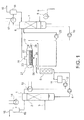
- FIG. 6 is a schematic configuration diagram of the carbon dioxide separating and capturing apparatus of the sixth embodiment.
- the carbon dioxide separating and capturing apparatus of the present embodiment is different in that the state of the rich liquid fed to the second regenerative heat exchanger 21 is monitored compared with the first embodiment shown in FIG. 1 .
- a pressure adjusting valve 30, a measuring device 32 of a temperature of the rich liquid, and a measuring device 33 of a pressure of the rich liquid are provided on the rich liquid line between the first regenerative heat exchanger 5 and the rich liquid inlet 24 of the second regenerative heat exchanger 21.
- the pressure adjusting valve 30 adjusts the pressure of the rich liquid.
- the measuring device 32 of the temperature of the rich liquid and the measuring device 33 of the pressure of the rich liquid measure the temperature and the pressure of the rich liquid discharged from the first regenerative heat exchanger 5 (to be fed to the second regenerative heat exchanger 21) to report the measurement results to a controller 34.
- a measuring device 31 of a concentration of the carbon dioxide dissolved in the rich liquid is provided on the rich liquid line between a reservoir in the bottom portion of the absorption tower 1 and an inlet portion of the first regenerative heat exchanger 5.
- the measuring device 31 of the concentration of the carbon dioxide dissolved in the rich liquid measures a dissolved carbon dioxide concentration of the rich liquid discharged from the absorption tower 1 (to be fed to the first regenerative heat exchanger 5) to report the measurement result to the controller 34.
- the controller 34 has the gas-liquid equilibrium data of the absorption liquid used in the carbon dioxide separating and capturing apparatus. Thereby, the controller 34 calculates the pressure value at which the rich liquid starts to generate the gases in the first regenerative heat exchanger 5, on the basis of the measured values obtained from the measuring device 31 of the concentration of the dissolved carbon dioxide in the rich liquid and the measuring device 32 of the temperature of the rich liquid. Then, the controller 34 controls the adjustment valve 30 so that an outlet pressure of the first regenerative heat exchanger 5, that is, the measured value from the measuring device 33 of the pressure of the rich liquid is equal to or greater than the calculated pressure value.
- the rich liquid can be maintained stably in the liquid phase at the first regenerative heat exchanger 5, and in the two phase of the gas and the liquid at the second regenerative heat exchanger 21, which allows to operate stably.
- the rich liquid is heated with the lean liquid in the liquid phase at the first regenerative heat exchanger 5 as similar to the first embodiment. Therefore, the device can be made compact. Moreover, deterioration of heat transfer performance due to drift flow can be suppressed to attain stable operation. Releasing the gas from the rich liquid at the second regenerative heat exchanger 21 enables latent heat generated during the steam generation and dissociation of the carbon dioxide gas to be used, which increases the quantity of the heat recovery from the lean liquid to be increased.
- FIG. 7 is a schematic configuration diagram of the carbon dioxide separating and capturing apparatus of the seventh embodiment.
- the carbon dioxide separating and capturing apparatus of the present embodiment is different in that the rich liquid discharged from the absorption tower 1 is divided into two, one of them is fed to the first regenerative heat exchanger 5 and the other is fed to a carbon dioxide generating device 36 compared with the first embodiment shown in FIG. 1 .
- the rich liquid discharged from the absorption tower 1 is divided into a first rich liquid R1 and a second rich liquid R2 at a flow divider 35.
- the first rich liquid R1 is fed to the first regenerative heat exchanger 5 and undergoes heat exchange with the lean liquid to be heated.
- the first rich liquid R1 is discharged in a liquid phase from the first regenerative heat exchanger 5 and further heated at the second regenerative heat exchanger 21 to be in two phases of a gas and a liquid.
- the second rich liquid R2 is fed to the carbon dioxide generating device 36.
- the carbon dioxide generating device (heat exchanger) 36 heats the second rich liquid R2 by using a hot gas discharged from the top portion of the regeneration tower 6. Thereby, since heat held by the gas discharged from the top portion of the regeneration tower 6 can be captured to the second rich liquid R2, an amount of energy input to the reboiler 8 can further be reduced.
- the rich liquid is heated with the lean liquid in the liquid phase at the first regenerative heat exchanger 5 as similar to the first embodiment. Therefore, the device can be made compact. Moreover, deterioration of heat transfer performance due to drift flow can be suppressed to attain stable operation. Releasing the gas from the rich liquid at the second regenerative heat exchanger 21 enables latent heat generated during the steam generation and dissociation of the carbon dioxide gas to be used, which increases the quantity of the heat recovery from the lean liquid to be increased.
- a recovery quantity of heat at the regenerative heat exchangers can be increased and the carbon dioxide separating and capturing apparatus can be stably operated.
Landscapes
- Chemical & Material Sciences (AREA)
- Engineering & Computer Science (AREA)
- Analytical Chemistry (AREA)
- General Chemical & Material Sciences (AREA)
- Oil, Petroleum & Natural Gas (AREA)
- Chemical Kinetics & Catalysis (AREA)
- Gas Separation By Absorption (AREA)
- Treating Waste Gases (AREA)
- Carbon And Carbon Compounds (AREA)
- Chimneys And Flues (AREA)
- Heat-Exchange Devices With Radiators And Conduit Assemblies (AREA)
- Physics & Mathematics (AREA)
- Mechanical Engineering (AREA)
- Thermal Sciences (AREA)
- General Engineering & Computer Science (AREA)
Claims (4)
- Vorrichtung zur Trennung und zum Auffangen von Kohlendioxid, die aufweist:einen Absorptionsturm (1), in den ein Gas eingeführt wird, das Kohlendioxid enthält, wobei der Absorptionsturm ausgebildet ist, damit das Gas eine Absorptionsflüssigkeit für das Absorbieren des Kohlendioxides kontaktieren kann, und um eine reiche Flüssigkeit abzulassen, die die Absorptionsflüssigkeit ist, die das Kohlendioxid absorbiert hat;einen Regenerationsturm (6), der ausgebildet ist, um die Absorptionsflüssigkeit zu erwärmen, um zu veranlassen, dass die Absorptionsflüssigkeit ein Gas freigibt, das das Kohlendioxid enthält, und um eine magere Flüssigkeit abzulassen, deren Konzentration von gelöstem Kohlendioxid niedriger ist als eine Konzentration des gelösten Kohlendioxides in der reichen Flüssigkeit; undeinen ersten und zweiten Regenerativwärmetauscher (5, 21), die ausgebildet sind, um die reiche Flüssigkeit bei Verwendung der mageren Flüssigkeit zu erwärmen,wobeider erste Regenerativwärmetauscher ein Wärmetauscher in Plattenausführung ist, die reiche Flüssigkeit erwärmt, die vom Absorptionsturm abgelassen wird, indem die magere Flüssigkeit benutzt wird, die vom zweiten Regenerativwärmetauscher abgelassen wird, und die reiche Flüssigkeit in einer flüssigen Phase ablässt,der zweite Regenerativwärmetauscher ein Wärmetauscher in Rohrbündelausführung ist, die reiche Flüssigkeit in der flüssigen Phase erwärmt, die vom ersten Regenerativwärmetauscher abgelassen wird, indem die magere Flüssigkeit benutzt wird, die vom Regenerationsturm abgelassen wird, und verursacht, dass die reiche Flüssigkeit einen Dampf erzeugt und ein Kohlendioxidgas freigibt,die magere Flüssigkeit, die vom ersten Regenerativwärmetauscher abgelassen wird, dem Absorptionsturm zugeführt wird, unddie reiche Flüssigkeit, der Dampf und das Kohlendioxidgas, die vom zweiten Regenerativwärmetauscher abgelassen werden, dem Regenerationsturm zugeführt werden,wobei die Vorrichtung außerdem aufweist:eine erste Messvorrichtung (31), die ausgebildet ist, um die Konzentration des gelösten Kohlendioxides in der reichen Flüssigkeit zu messen, die dem ersten Regenerativwärmetauscher zugeführt wird;eine zweite Messvorrichtung (32), die ausgebildet ist, um eine Temperatur der reichen Flüssigkeit zu messen, die vom ersten Regenerativwärmetauscher abgelassen wird;eine dritte Messvorrichtung (33), die ausgebildet ist, um einen Druck der reichen Flüssigkeit zu messen, die vom ersten Regenerativwärmetauscher abgelassen wird;ein Druckregulierventil (30), das ausgebildet ist, um den Druck der reichen Flüssigkeit zu regulieren, die vom ersten Regenerativwärmetauscher abgelassen wird; undeinen Regler (34), der ausgebildet ist, um bei Benutzung der Werte der ersten und der zweiten Messvorrichtung und der Gas-Flüssigkeits-Gleichgewichtsdaten der Absorptionsflüssigkeit einen Druckwert zu berechnen, bei dem die reiche Flüssigkeit, die vom ersten Regenerativwärmetauscher abgelassen wird, in der flüssigen Phase aufrechterhalten wird, und um das Druckregulierventil zu steuern, so dass ein Messergebnis der dritten Messvorrichtung gleich oder größer ist als der berechnete Druckwert.
- Vorrichtung nach Anspruch 1, die außerdem einen Strömungsteiler (35) aufweist, der ausgebildet ist, um die reiche Flüssigkeit, die vom Absorptionsturm abgelassen wird, in eine erste reiche Flüssigkeit und eine zweite reiche Flüssigkeit aufzuteilen,
wobei
die erste reiche Flüssigkeit dem ersten Regenerativwärmetauscher zugeführt wird, und
die zweite reiche Flüssigkeit mit einem Gas erwärmt wird, das das Kohlendioxid enthält, und das aus dem Regenerationsturm abgelassen wird. - Vorrichtung nach Anspruch 1, bei der der zweite Regenerativwärmetauscher ein Wärmetauscher in Röhrenkessel-Umlauf-Ausführung ist.
- Verfahren zum Betätigen einer Vorrichtung zur Trennung und zum Auffangen von Kohlendioxid, die einen Absorptionsturm (1), einen Regenerationsturm (6), einen ersten Regenerativwärmetauscher (5) in Plattenausführung und einen zweiten Regenerativwärmetauscher (21) in Rohrbündelausführung umfasst, wobei das Verfahren die folgenden Schritte aufweist:Zulassen, dass ein Gas, das Kohlendioxid enthält, mit einer mageren Flüssigkeit in Kontakt kommt, die vom ersten Regenerativwärmetauscher im Absorptionsturm abgelassen wird, und Ablassen einer reichen Flüssigkeit, die die Absorptionsflüssigkeit ist, die das Kohlendioxid absorbiert hat, aus dem Absorptionsturm;Erwärmen der reichen Flüssigkeit, die aus dem Absorptionsturm abgelassen wird, bei Benutzung der mageren Flüssigkeit, die vom zweiten Regenerativwärmetauscher in den ersten Regenerativwärmetauscher abgelassen wird, und Ablassen der reichen Flüssigkeit in einer flüssigen Phase;Erwärmen der reichen Flüssigkeit in der flüssigen Phase, die vom ersten Regenerativwärmetauscher abgelassen wird, indem die magere Flüssigkeit verwendet wird, die vom Regenerationsturm in den zweiten Regenerativwärmetauscher abgelassen wird, und Zulassen, dass die reiche Flüssigkeit einen Dampf erzeugt und ein Kohlendioxidgas freigibt; undZuführen der reichen Flüssigkeit, des Dampfes und des Kohlendioxidgases, die vom zweiten Regenerativwärmetauscher abgelassen werden, zum Regenerationsturm, um zu veranlassen, dass die reiche Flüssigkeit ein Gas freigibt, das das Kohlendioxid enthält, und Ablassen der mageren Flüssigkeit, deren Konzentration an gelöstem Kohlendioxid niedriger ist als eine Konzentration des gelösten Kohlendioxides in der reichen Flüssigkeit,wobei das Verfahren außerdem die folgenden Schritte aufweist:Messen der Konzentration des gelösten Kohlendioxides in der reichen Flüssigkeit, die dem ersten Regenerativwärmetauscher zugeführt wird, mittels Verwenden einer ersten Messvorrichtung (31);Messen einer Temperatur der reichen Flüssigkeit, die vom ersten Regenerativwärmetauscher abgelassen wird, mittels Verwenden einer zweiten Messvorrichtung (32);Messen eines Druckes der reichen Flüssigkeit, die vom ersten Regenerativwärmetauscher abgelassen wird, mittels Verwenden einer dritten Messvorrichtung (33);Berechnen eines Druckwertes, bei dem die reiche Flüssigkeit, die vom ersten Regenerativwärmetauscher abgelassen wird, ihn in der flüssigen Phase aufrecht erhält, indem die Werte der ersten und zweiten Messvorrichtung und die Gas-Flüssigkeits-Gleichgewichtsdaten der Absorptionsflüssigkeit verwendet werden; undSteuern eines Druckregulierventils (30), das ausgebildet ist, um den Druck der reichen Flüssigkeit zu regulieren, die vom ersten Regenerativwärmetauscher abgelassen wird, so dass ein Messergebnis der dritten Messvorrichtung gleich oder größer als der berechnete Druckwert ist.
Applications Claiming Priority (1)
| Application Number | Priority Date | Filing Date | Title |
|---|---|---|---|
| JP2013106435A JP6157925B2 (ja) | 2013-05-20 | 2013-05-20 | 二酸化炭素分離回収装置及びその運転方法 |
Publications (2)
| Publication Number | Publication Date |
|---|---|
| EP2805757A1 EP2805757A1 (de) | 2014-11-26 |
| EP2805757B1 true EP2805757B1 (de) | 2015-12-02 |
Family
ID=49999843
Family Applications (1)
| Application Number | Title | Priority Date | Filing Date |
|---|---|---|---|
| EP14152866.1A Not-in-force EP2805757B1 (de) | 2013-05-20 | 2014-01-28 | Vorrichtung zur Trennung und zum Sammeln von Kohlendioxid und Betriebsverfahren dafür |
Country Status (5)
| Country | Link |
|---|---|
| US (1) | US9248397B2 (de) |
| EP (1) | EP2805757B1 (de) |
| JP (1) | JP6157925B2 (de) |
| CN (1) | CN104174257B (de) |
| AU (1) | AU2014200565B2 (de) |
Families Citing this family (21)
| Publication number | Priority date | Publication date | Assignee | Title |
|---|---|---|---|---|
| KR101421611B1 (ko) * | 2013-06-04 | 2014-07-22 | 한국전력기술 주식회사 | 감압 및 상 분리를 이용하여 현열 회수 효율을 개선한 이산화탄소 분리장치 |
| KR101550618B1 (ko) * | 2014-01-14 | 2015-09-07 | 현대자동차 주식회사 | 리보일링 장치 및 이를 구비한 재생탑 |
| KR101646125B1 (ko) * | 2015-02-16 | 2016-08-12 | 현대자동차 주식회사 | 가스 포집 플랜트 |
| JP6618840B2 (ja) * | 2016-03-14 | 2019-12-11 | 株式会社東芝 | 二酸化炭素回収システムおよび二酸化炭素回収方法 |
| CN106731600A (zh) * | 2016-12-20 | 2017-05-31 | 新疆敦华石油技术股份有限公司 | 一种二氧化碳捕集液化装置 |
| CN106914104B (zh) * | 2017-04-18 | 2022-08-12 | 长沙紫宸科技开发有限公司 | 一种适应于连续捕集烟气中二氧化碳的吸收-再生器 |
| CN107243258A (zh) * | 2017-07-20 | 2017-10-13 | 中国华能集团清洁能源技术研究院有限公司 | 一种电厂烟气中酸性气体捕集溶液的再生装置与方法 |
| CN108801036A (zh) * | 2018-06-22 | 2018-11-13 | 沈阳汇博热能设备有限公司 | 一种釜式重沸器管束限位装置 |
| CN114632402B (zh) * | 2020-12-16 | 2022-11-11 | 中冶京诚工程技术有限公司 | 烟气二氧化碳捕集系统的捕集方法 |
| CN113332855A (zh) * | 2021-06-29 | 2021-09-03 | 西安热工研究院有限公司 | 用于有机胺二氧化碳捕集的填料吸收塔及碳捕集吸收系统 |
| CN113828120A (zh) * | 2021-11-01 | 2021-12-24 | 中国船舶重工集团公司第七一一研究所 | 一种低能耗船舶柴油机烟气co2捕集系统 |
| CN114272735B (zh) * | 2021-12-27 | 2022-11-25 | 北京华源泰盟节能设备有限公司 | 一种烟气余热利用与碳捕集一体化系统 |
| JP2023118528A (ja) * | 2022-02-15 | 2023-08-25 | 本田技研工業株式会社 | 内燃機関のco2分離装置 |
| CN114712990B (zh) * | 2022-03-17 | 2023-08-08 | 中国华能集团清洁能源技术研究院有限公司 | 一种co2再生装置及工艺方法 |
| CN115212710A (zh) * | 2022-07-22 | 2022-10-21 | 碳索(杭州)能源环境科技有限公司 | 一种适用于超低浓度co2烟气的碳捕集系统 |
| JP2026504166A (ja) * | 2023-01-27 | 2026-02-03 | サステイナブル・エナジー・ソリューションズ・インコーポレーテッド | ガスストリームからの成分分離 |
| CN116328499A (zh) * | 2023-03-08 | 2023-06-27 | 中国华能集团清洁能源技术研究院有限公司 | 微波再生解吸装置和再生解吸系统 |
| CN116474523B (zh) * | 2023-03-22 | 2025-07-29 | 中国科学院工程热物理研究所 | 一种基于吸收液存储的错峰能源利用碳捕集系统 |
| CN119488792B (zh) * | 2023-08-16 | 2025-11-04 | 中国石油化工股份有限公司 | 一种气体净化设备、气体净化系统和方法 |
| US20260027511A1 (en) * | 2024-07-25 | 2026-01-29 | Mitsubishi Heavy Industries, Ltd. | Reboiler and acid gas recovery system |
| CN119771122B (zh) * | 2024-12-27 | 2025-07-18 | 广东华清双碳环境科技有限公司 | 一种基于ccus的烟气碳捕集系统 |
Family Cites Families (10)
| Publication number | Priority date | Publication date | Assignee | Title |
|---|---|---|---|---|
| JP2882950B2 (ja) * | 1992-09-16 | 1999-04-19 | 関西電力株式会社 | 燃焼排ガス中の二酸化炭素を除去する方法 |
| JP4274846B2 (ja) | 2003-04-30 | 2009-06-10 | 三菱重工業株式会社 | 二酸化炭素の回収方法及びそのシステム |
| JP4690659B2 (ja) | 2004-03-15 | 2011-06-01 | 三菱重工業株式会社 | Co2回収装置 |
| DE102005040531A1 (de) | 2005-08-26 | 2007-03-22 | Siemens Ag | Stromquelle, Steuervorrichtung und Verfahren zum Betreiben der Steuervorrichtung |
| JP2010201379A (ja) * | 2009-03-04 | 2010-09-16 | Toshiba Corp | 二酸化炭素回収システム |
| JP5383338B2 (ja) * | 2009-06-17 | 2014-01-08 | 三菱重工業株式会社 | Co2回収装置及びco2回収方法 |
| JP5697411B2 (ja) | 2010-11-17 | 2015-04-08 | 株式会社東芝 | 二酸化炭素回収装置および二酸化炭素回収方法 |
| US8845790B2 (en) * | 2011-01-06 | 2014-09-30 | Alstom Technology Ltd | Method and system for removal of gaseous contaminants |
| JP5658101B2 (ja) * | 2011-07-06 | 2015-01-21 | Jfeスチール株式会社 | Co2回収装置及び回収方法 |
| EP2570164B1 (de) | 2011-09-16 | 2013-10-23 | MT-Biomethan GmbH | Verfahren und Vorrichtung zur absorptiven Entfernung von Kohlendioxid aus Biogas |
-
2013
- 2013-05-20 JP JP2013106435A patent/JP6157925B2/ja not_active Expired - Fee Related
-
2014
- 2014-01-24 US US14/163,268 patent/US9248397B2/en not_active Expired - Fee Related
- 2014-01-28 EP EP14152866.1A patent/EP2805757B1/de not_active Not-in-force
- 2014-01-31 AU AU2014200565A patent/AU2014200565B2/en not_active Ceased
- 2014-02-21 CN CN201410059738.5A patent/CN104174257B/zh not_active Expired - Fee Related
Also Published As
| Publication number | Publication date |
|---|---|
| US9248397B2 (en) | 2016-02-02 |
| AU2014200565B2 (en) | 2015-10-01 |
| JP6157925B2 (ja) | 2017-07-05 |
| CN104174257A (zh) | 2014-12-03 |
| CN104174257B (zh) | 2016-09-07 |
| JP2014226583A (ja) | 2014-12-08 |
| US20140338394A1 (en) | 2014-11-20 |
| EP2805757A1 (de) | 2014-11-26 |
| AU2014200565A1 (en) | 2014-12-04 |
Similar Documents
| Publication | Publication Date | Title |
|---|---|---|
| EP2805757B1 (de) | Vorrichtung zur Trennung und zum Sammeln von Kohlendioxid und Betriebsverfahren dafür | |
| JP5331587B2 (ja) | 二酸化炭素回収システム | |
| CA2754466C (en) | Carbon dioxide separation recovery system and method of measuring amount of reboiler input heat | |
| US10173166B2 (en) | Carbon dioxide recovering apparatus and method for operating the same | |
| EP2998011B1 (de) | Kohlendioxidabscheidungsvorrichtung und verfahren zur steuerung des betriebs der kohlendioxidabscheidungsvorrichtung | |
| US20150027164A1 (en) | Carbon dioxide separating and capturing system and method of operating same | |
| US9901871B2 (en) | System for chemically absorbing carbon dioxide in combustion exhaust gas | |
| US20150174531A1 (en) | Carbon dioxide recovery apparatus and carbon dioxide recovery method | |
| JP5646524B2 (ja) | 二酸化炭素分離回収システムおよびその運転方法 | |
| JP2010201379A (ja) | 二酸化炭素回収システム | |
| JP6649736B2 (ja) | ガス捕集プラント | |
| JP5586358B2 (ja) | 二酸化炭素分離回収システム及びその運転方法 | |
| JP6560938B2 (ja) | 吸収反応セパレータを備えた吸収塔 | |
| US20230364549A1 (en) | Gas-treating device | |
| JP6602576B2 (ja) | 還流セパレータを備えたガス凝縮装置 | |
| JP6618840B2 (ja) | 二酸化炭素回収システムおよび二酸化炭素回収方法 | |
| JP7623927B2 (ja) | 吸収装置、ガス処理装置、吸収方法及びガス処理方法 |
Legal Events
| Date | Code | Title | Description |
|---|---|---|---|
| PUAI | Public reference made under article 153(3) epc to a published international application that has entered the european phase |
Free format text: ORIGINAL CODE: 0009012 |
|
| 17P | Request for examination filed |
Effective date: 20140128 |
|
| AK | Designated contracting states |
Kind code of ref document: A1 Designated state(s): AL AT BE BG CH CY CZ DE DK EE ES FI FR GB GR HR HU IE IS IT LI LT LU LV MC MK MT NL NO PL PT RO RS SE SI SK SM TR |
|
| AX | Request for extension of the european patent |
Extension state: BA ME |
|
| GRAP | Despatch of communication of intention to grant a patent |
Free format text: ORIGINAL CODE: EPIDOSNIGR1 |
|
| RIC1 | Information provided on ipc code assigned before grant |
Ipc: B01D 53/14 20060101AFI20150430BHEP |
|
| INTG | Intention to grant announced |
Effective date: 20150601 |
|
| GRAS | Grant fee paid |
Free format text: ORIGINAL CODE: EPIDOSNIGR3 |
|
| GRAA | (expected) grant |
Free format text: ORIGINAL CODE: 0009210 |
|
| AK | Designated contracting states |
Kind code of ref document: B1 Designated state(s): AL AT BE BG CH CY CZ DE DK EE ES FI FR GB GR HR HU IE IS IT LI LT LU LV MC MK MT NL NO PL PT RO RS SE SI SK SM TR |
|
| REG | Reference to a national code |
Ref country code: GB Ref legal event code: FG4D |
|
| REG | Reference to a national code |
Ref country code: AT Ref legal event code: REF Ref document number: 763370 Country of ref document: AT Kind code of ref document: T Effective date: 20151215 Ref country code: CH Ref legal event code: EP |
|
| REG | Reference to a national code |
Ref country code: IE Ref legal event code: FG4D |
|
| REG | Reference to a national code |
Ref country code: DE Ref legal event code: R096 Ref document number: 602014000486 Country of ref document: DE |
|
| REG | Reference to a national code |
Ref country code: NL Ref legal event code: MP Effective date: 20160302 |
|
| REG | Reference to a national code |
Ref country code: LT Ref legal event code: MG4D |
|
| REG | Reference to a national code |
Ref country code: AT Ref legal event code: MK05 Ref document number: 763370 Country of ref document: AT Kind code of ref document: T Effective date: 20151202 |
|
| PG25 | Lapsed in a contracting state [announced via postgrant information from national office to epo] |
Ref country code: LT Free format text: LAPSE BECAUSE OF FAILURE TO SUBMIT A TRANSLATION OF THE DESCRIPTION OR TO PAY THE FEE WITHIN THE PRESCRIBED TIME-LIMIT Effective date: 20151202 Ref country code: ES Free format text: LAPSE BECAUSE OF FAILURE TO SUBMIT A TRANSLATION OF THE DESCRIPTION OR TO PAY THE FEE WITHIN THE PRESCRIBED TIME-LIMIT Effective date: 20151202 Ref country code: NO Free format text: LAPSE BECAUSE OF FAILURE TO SUBMIT A TRANSLATION OF THE DESCRIPTION OR TO PAY THE FEE WITHIN THE PRESCRIBED TIME-LIMIT Effective date: 20160302 |
|
| PG25 | Lapsed in a contracting state [announced via postgrant information from national office to epo] |
Ref country code: SE Free format text: LAPSE BECAUSE OF FAILURE TO SUBMIT A TRANSLATION OF THE DESCRIPTION OR TO PAY THE FEE WITHIN THE PRESCRIBED TIME-LIMIT Effective date: 20151202 Ref country code: LV Free format text: LAPSE BECAUSE OF FAILURE TO SUBMIT A TRANSLATION OF THE DESCRIPTION OR TO PAY THE FEE WITHIN THE PRESCRIBED TIME-LIMIT Effective date: 20151202 Ref country code: NL Free format text: LAPSE BECAUSE OF FAILURE TO SUBMIT A TRANSLATION OF THE DESCRIPTION OR TO PAY THE FEE WITHIN THE PRESCRIBED TIME-LIMIT Effective date: 20151202 Ref country code: RS Free format text: LAPSE BECAUSE OF FAILURE TO SUBMIT A TRANSLATION OF THE DESCRIPTION OR TO PAY THE FEE WITHIN THE PRESCRIBED TIME-LIMIT Effective date: 20151202 Ref country code: AT Free format text: LAPSE BECAUSE OF FAILURE TO SUBMIT A TRANSLATION OF THE DESCRIPTION OR TO PAY THE FEE WITHIN THE PRESCRIBED TIME-LIMIT Effective date: 20151202 Ref country code: GR Free format text: LAPSE BECAUSE OF FAILURE TO SUBMIT A TRANSLATION OF THE DESCRIPTION OR TO PAY THE FEE WITHIN THE PRESCRIBED TIME-LIMIT Effective date: 20160303 Ref country code: FI Free format text: LAPSE BECAUSE OF FAILURE TO SUBMIT A TRANSLATION OF THE DESCRIPTION OR TO PAY THE FEE WITHIN THE PRESCRIBED TIME-LIMIT Effective date: 20151202 Ref country code: PL Free format text: LAPSE BECAUSE OF FAILURE TO SUBMIT A TRANSLATION OF THE DESCRIPTION OR TO PAY THE FEE WITHIN THE PRESCRIBED TIME-LIMIT Effective date: 20151202 Ref country code: BE Free format text: LAPSE BECAUSE OF NON-PAYMENT OF DUE FEES Effective date: 20160131 |
|
| PG25 | Lapsed in a contracting state [announced via postgrant information from national office to epo] |
Ref country code: IS Free format text: LAPSE BECAUSE OF FAILURE TO SUBMIT A TRANSLATION OF THE DESCRIPTION OR TO PAY THE FEE WITHIN THE PRESCRIBED TIME-LIMIT Effective date: 20151202 |
|
| PG25 | Lapsed in a contracting state [announced via postgrant information from national office to epo] |
Ref country code: IT Free format text: LAPSE BECAUSE OF FAILURE TO SUBMIT A TRANSLATION OF THE DESCRIPTION OR TO PAY THE FEE WITHIN THE PRESCRIBED TIME-LIMIT Effective date: 20151202 Ref country code: CZ Free format text: LAPSE BECAUSE OF FAILURE TO SUBMIT A TRANSLATION OF THE DESCRIPTION OR TO PAY THE FEE WITHIN THE PRESCRIBED TIME-LIMIT Effective date: 20151202 |
|
| REG | Reference to a national code |
Ref country code: DE Ref legal event code: R119 Ref document number: 602014000486 Country of ref document: DE |
|
| PG25 | Lapsed in a contracting state [announced via postgrant information from national office to epo] |
Ref country code: IS Free format text: LAPSE BECAUSE OF FAILURE TO SUBMIT A TRANSLATION OF THE DESCRIPTION OR TO PAY THE FEE WITHIN THE PRESCRIBED TIME-LIMIT Effective date: 20160402 Ref country code: RO Free format text: LAPSE BECAUSE OF FAILURE TO SUBMIT A TRANSLATION OF THE DESCRIPTION OR TO PAY THE FEE WITHIN THE PRESCRIBED TIME-LIMIT Effective date: 20151202 Ref country code: EE Free format text: LAPSE BECAUSE OF FAILURE TO SUBMIT A TRANSLATION OF THE DESCRIPTION OR TO PAY THE FEE WITHIN THE PRESCRIBED TIME-LIMIT Effective date: 20151202 Ref country code: PT Free format text: LAPSE BECAUSE OF FAILURE TO SUBMIT A TRANSLATION OF THE DESCRIPTION OR TO PAY THE FEE WITHIN THE PRESCRIBED TIME-LIMIT Effective date: 20160404 Ref country code: SK Free format text: LAPSE BECAUSE OF FAILURE TO SUBMIT A TRANSLATION OF THE DESCRIPTION OR TO PAY THE FEE WITHIN THE PRESCRIBED TIME-LIMIT Effective date: 20151202 Ref country code: LU Free format text: LAPSE BECAUSE OF FAILURE TO SUBMIT A TRANSLATION OF THE DESCRIPTION OR TO PAY THE FEE WITHIN THE PRESCRIBED TIME-LIMIT Effective date: 20160128 Ref country code: SM Free format text: LAPSE BECAUSE OF FAILURE TO SUBMIT A TRANSLATION OF THE DESCRIPTION OR TO PAY THE FEE WITHIN THE PRESCRIBED TIME-LIMIT Effective date: 20151202 |
|
| PG25 | Lapsed in a contracting state [announced via postgrant information from national office to epo] |
Ref country code: MC Free format text: LAPSE BECAUSE OF FAILURE TO SUBMIT A TRANSLATION OF THE DESCRIPTION OR TO PAY THE FEE WITHIN THE PRESCRIBED TIME-LIMIT Effective date: 20151202 |
|
| PLBE | No opposition filed within time limit |
Free format text: ORIGINAL CODE: 0009261 |
|
| STAA | Information on the status of an ep patent application or granted ep patent |
Free format text: STATUS: NO OPPOSITION FILED WITHIN TIME LIMIT |
|
| REG | Reference to a national code |
Ref country code: FR Ref legal event code: ST Effective date: 20160930 |
|
| PG25 | Lapsed in a contracting state [announced via postgrant information from national office to epo] |
Ref country code: DK Free format text: LAPSE BECAUSE OF FAILURE TO SUBMIT A TRANSLATION OF THE DESCRIPTION OR TO PAY THE FEE WITHIN THE PRESCRIBED TIME-LIMIT Effective date: 20151202 Ref country code: DE Free format text: LAPSE BECAUSE OF NON-PAYMENT OF DUE FEES Effective date: 20160802 |
|
| REG | Reference to a national code |
Ref country code: IE Ref legal event code: MM4A |
|
| 26N | No opposition filed |
Effective date: 20160905 |
|
| PG25 | Lapsed in a contracting state [announced via postgrant information from national office to epo] |
Ref country code: FR Free format text: LAPSE BECAUSE OF NON-PAYMENT OF DUE FEES Effective date: 20160202 Ref country code: SI Free format text: LAPSE BECAUSE OF FAILURE TO SUBMIT A TRANSLATION OF THE DESCRIPTION OR TO PAY THE FEE WITHIN THE PRESCRIBED TIME-LIMIT Effective date: 20151202 |
|
| PG25 | Lapsed in a contracting state [announced via postgrant information from national office to epo] |
Ref country code: BE Free format text: LAPSE BECAUSE OF FAILURE TO SUBMIT A TRANSLATION OF THE DESCRIPTION OR TO PAY THE FEE WITHIN THE PRESCRIBED TIME-LIMIT Effective date: 20151202 |
|
| PG25 | Lapsed in a contracting state [announced via postgrant information from national office to epo] |
Ref country code: IE Free format text: LAPSE BECAUSE OF NON-PAYMENT OF DUE FEES Effective date: 20160128 |
|
| PG25 | Lapsed in a contracting state [announced via postgrant information from national office to epo] |
Ref country code: MT Free format text: LAPSE BECAUSE OF FAILURE TO SUBMIT A TRANSLATION OF THE DESCRIPTION OR TO PAY THE FEE WITHIN THE PRESCRIBED TIME-LIMIT Effective date: 20151202 |
|
| REG | Reference to a national code |
Ref country code: CH Ref legal event code: PL |
|
| PG25 | Lapsed in a contracting state [announced via postgrant information from national office to epo] |
Ref country code: LI Free format text: LAPSE BECAUSE OF NON-PAYMENT OF DUE FEES Effective date: 20170131 Ref country code: CH Free format text: LAPSE BECAUSE OF NON-PAYMENT OF DUE FEES Effective date: 20170131 |
|
| PG25 | Lapsed in a contracting state [announced via postgrant information from national office to epo] |
Ref country code: HU Free format text: LAPSE BECAUSE OF FAILURE TO SUBMIT A TRANSLATION OF THE DESCRIPTION OR TO PAY THE FEE WITHIN THE PRESCRIBED TIME-LIMIT; INVALID AB INITIO Effective date: 20140128 |
|
| PG25 | Lapsed in a contracting state [announced via postgrant information from national office to epo] |
Ref country code: MK Free format text: LAPSE BECAUSE OF FAILURE TO SUBMIT A TRANSLATION OF THE DESCRIPTION OR TO PAY THE FEE WITHIN THE PRESCRIBED TIME-LIMIT Effective date: 20151202 Ref country code: MT Free format text: LAPSE BECAUSE OF FAILURE TO SUBMIT A TRANSLATION OF THE DESCRIPTION OR TO PAY THE FEE WITHIN THE PRESCRIBED TIME-LIMIT Effective date: 20160131 Ref country code: HR Free format text: LAPSE BECAUSE OF FAILURE TO SUBMIT A TRANSLATION OF THE DESCRIPTION OR TO PAY THE FEE WITHIN THE PRESCRIBED TIME-LIMIT Effective date: 20151202 Ref country code: CY Free format text: LAPSE BECAUSE OF FAILURE TO SUBMIT A TRANSLATION OF THE DESCRIPTION OR TO PAY THE FEE WITHIN THE PRESCRIBED TIME-LIMIT Effective date: 20151202 |
|
| PG25 | Lapsed in a contracting state [announced via postgrant information from national office to epo] |
Ref country code: BG Free format text: LAPSE BECAUSE OF FAILURE TO SUBMIT A TRANSLATION OF THE DESCRIPTION OR TO PAY THE FEE WITHIN THE PRESCRIBED TIME-LIMIT Effective date: 20151202 |
|
| PG25 | Lapsed in a contracting state [announced via postgrant information from national office to epo] |
Ref country code: AL Free format text: LAPSE BECAUSE OF FAILURE TO SUBMIT A TRANSLATION OF THE DESCRIPTION OR TO PAY THE FEE WITHIN THE PRESCRIBED TIME-LIMIT Effective date: 20151202 Ref country code: TR Free format text: LAPSE BECAUSE OF FAILURE TO SUBMIT A TRANSLATION OF THE DESCRIPTION OR TO PAY THE FEE WITHIN THE PRESCRIBED TIME-LIMIT Effective date: 20151202 |
|
| PGFP | Annual fee paid to national office [announced via postgrant information from national office to epo] |
Ref country code: GB Payment date: 20190123 Year of fee payment: 6 |
|
| GBPC | Gb: european patent ceased through non-payment of renewal fee |
Effective date: 20200128 |
|
| PG25 | Lapsed in a contracting state [announced via postgrant information from national office to epo] |
Ref country code: GB Free format text: LAPSE BECAUSE OF NON-PAYMENT OF DUE FEES Effective date: 20200128 |