EP2805425B1 - Datenübertragung in einem breitband-funkkommunikation system - Google Patents
Datenübertragung in einem breitband-funkkommunikation system Download PDFInfo
- Publication number
- EP2805425B1 EP2805425B1 EP13702081.4A EP13702081A EP2805425B1 EP 2805425 B1 EP2805425 B1 EP 2805425B1 EP 13702081 A EP13702081 A EP 13702081A EP 2805425 B1 EP2805425 B1 EP 2805425B1
- Authority
- EP
- European Patent Office
- Prior art keywords
- transmission
- radar
- terminal
- interval
- radar pulses
- Prior art date
- Legal status (The legal status is an assumption and is not a legal conclusion. Google has not performed a legal analysis and makes no representation as to the accuracy of the status listed.)
- Active
Links
Images



Classifications
-
- G—PHYSICS
- G01—MEASURING; TESTING
- G01S—RADIO DIRECTION-FINDING; RADIO NAVIGATION; DETERMINING DISTANCE OR VELOCITY BY USE OF RADIO WAVES; LOCATING OR PRESENCE-DETECTING BY USE OF THE REFLECTION OR RERADIATION OF RADIO WAVES; ANALOGOUS ARRANGEMENTS USING OTHER WAVES
- G01S7/00—Details of systems according to groups G01S13/00, G01S15/00, G01S17/00
- G01S7/02—Details of systems according to groups G01S13/00, G01S15/00, G01S17/00 of systems according to group G01S13/00
- G01S7/021—Auxiliary means for detecting or identifying radar signals or the like, e.g. radar jamming signals
-
- H—ELECTRICITY
- H04—ELECTRIC COMMUNICATION TECHNIQUE
- H04W—WIRELESS COMMUNICATION NETWORKS
- H04W72/00—Local resource management
- H04W72/50—Allocation or scheduling criteria for wireless resources
- H04W72/54—Allocation or scheduling criteria for wireless resources based on quality criteria
- H04W72/542—Allocation or scheduling criteria for wireless resources based on quality criteria using measured or perceived quality
-
- H—ELECTRICITY
- H04—ELECTRIC COMMUNICATION TECHNIQUE
- H04B—TRANSMISSION
- H04B1/00—Details of transmission systems, not covered by a single one of groups H04B3/00 - H04B13/00; Details of transmission systems not characterised by the medium used for transmission
- H04B1/38—Transceivers, i.e. devices in which transmitter and receiver form a structural unit and in which at least one part is used for functions of transmitting and receiving
- H04B1/3805—Transceivers, i.e. devices in which transmitter and receiver form a structural unit and in which at least one part is used for functions of transmitting and receiving with built-in auxiliary receivers
-
- H—ELECTRICITY
- H04—ELECTRIC COMMUNICATION TECHNIQUE
- H04K—SECRET COMMUNICATION; JAMMING OF COMMUNICATION
- H04K3/00—Jamming of communication; Counter-measures
- H04K3/20—Countermeasures against jamming
- H04K3/22—Countermeasures against jamming including jamming detection and monitoring
- H04K3/224—Countermeasures against jamming including jamming detection and monitoring with countermeasures at transmission and/or reception of the jammed signal, e.g. stopping operation of transmitter or receiver, nulling or enhancing transmitted power in direction of or at frequency of jammer
-
- H—ELECTRICITY
- H04—ELECTRIC COMMUNICATION TECHNIQUE
- H04K—SECRET COMMUNICATION; JAMMING OF COMMUNICATION
- H04K3/00—Jamming of communication; Counter-measures
- H04K3/80—Jamming or countermeasure characterized by its function
- H04K3/82—Jamming or countermeasure characterized by its function related to preventing surveillance, interception or detection
- H04K3/822—Jamming or countermeasure characterized by its function related to preventing surveillance, interception or detection by detecting the presence of a surveillance, interception or detection
-
- H—ELECTRICITY
- H04—ELECTRIC COMMUNICATION TECHNIQUE
- H04W—WIRELESS COMMUNICATION NETWORKS
- H04W16/00—Network planning, e.g. coverage or traffic planning tools; Network deployment, e.g. resource partitioning or cells structures
- H04W16/14—Spectrum sharing arrangements between different networks
-
- H—ELECTRICITY
- H04—ELECTRIC COMMUNICATION TECHNIQUE
- H04W—WIRELESS COMMUNICATION NETWORKS
- H04W72/00—Local resource management
- H04W72/04—Wireless resource allocation
- H04W72/044—Wireless resource allocation based on the type of the allocated resource
- H04W72/0446—Resources in time domain, e.g. slots or frames
-
- H—ELECTRICITY
- H04—ELECTRIC COMMUNICATION TECHNIQUE
- H04K—SECRET COMMUNICATION; JAMMING OF COMMUNICATION
- H04K2203/00—Jamming of communication; Countermeasures
- H04K2203/10—Jamming or countermeasure used for a particular application
- H04K2203/18—Jamming or countermeasure used for a particular application for wireless local area networks or WLAN
-
- H—ELECTRICITY
- H04—ELECTRIC COMMUNICATION TECHNIQUE
- H04K—SECRET COMMUNICATION; JAMMING OF COMMUNICATION
- H04K3/00—Jamming of communication; Counter-measures
- H04K3/20—Countermeasures against jamming
- H04K3/22—Countermeasures against jamming including jamming detection and monitoring
- H04K3/224—Countermeasures against jamming including jamming detection and monitoring with countermeasures at transmission and/or reception of the jammed signal, e.g. stopping operation of transmitter or receiver, nulling or enhancing transmitted power in direction of or at frequency of jammer
- H04K3/226—Selection of non-jammed channel for communication
Definitions
- the present invention relates generally to transmission of data in a wireless communications system, and more specifically, but not exclusively, to a method and apparatus for transmitting data to allow improved detection of radar pulses on a channel of a broadband radio communications system using Dynamic Frequency Selection (DFS).
- DFS Dynamic Frequency Selection
- wireless communications systems such as point-to-point and point to multi-point broadband radio communications systems.
- bands within the wireless spectrum that were previously allocated for another use have been allocated for use by broadband radio communications systems, as either a licensed or unlicensed band.
- some bands for example bands at approximately 5.4 and 5.8 GHz, were formerly allocated exclusively for use by military radar systems. Since such systems are rarely used in most circumstances and at most locations, the bands have been made available for use in addition by, for example, broadband radio communications systems, provided that equipment used in these bands is arranged to detect radar pulses, and to cease transmission on a channel on which radar pulses are detected, so that interference with the operation of the radar may be avoided.
- DFS Dynamic Frequency Selection
- broadband radio communications equipment for operation in a band where DFS is required must be certified to meet specified requirements regarding probability of detection of radar transmissions.
- a broadband radio communication system arranged to transmit and receive in the same frequency channel such as a system operating according to a contention-based medium access control system
- the timing of the transmission of data packets is typically determined at least in part by the time of arrival, at a data interface, of the data packets to be transmitted.
- data packets may arrive at the data interface spaced apart in time by intervals such that, when transmitted, the transmission has a pulse repetition interval corresponding to an allowed pulse repetition interval of a radar system that the terminal is required to detect. Therefore, the probability of detection of radar pulses may be reduced, according to the arrangement of data packets arriving at the data interface.
- Patent application US2004/132411 discloses a method of radar detection in a WLAN system operating in a 5GHz range using a quiet time and a quiet period.
- a method of transmitting data packets from a terminal of a broadband radio communication system the terminal being capable of transmitting radio signals which may interfere with radar pulses, the radar pulses being transmitted with one or more pulse repetition intervals, the method comprising, for each of a plurality of transmission cycles in a transmission period:
- said inhibiting of the transmission of radio signals inhibits the transmission for a defined period to allow a confirmation of detection of radar pulses.
- the method comprises:
- repetition intervals may be controlled to improve a probability of detection for an expected pulse repetition interval, or an expected range of pulse repetition intervals of the radar.
- controlling of the transmission repetition intervals comprises:
- first and second patterns may be used alternately, so that first and second repetition intervals, also referred to as chunking intervals, are used in alternating periods, so that a probability of detecting a radar having a pulse repetition interval that corresponds to the first or second repetition intervals is increased.
- each of the plurality of second transmission repetition intervals is between 10% and 40% longer than each of the plurality of first transmission repetition intervals.
- the first and second transmission repetition intervals are selected to be within a range of allowed pulse repetition intervals of the radar pulses.
- the first and second transmission patterns are each activated for a respective activation period.
- the first and second activation periods are arranged to be activated alternately.
- the activation periods are each in the range 20 milliseconds to 200 milliseconds.
- the controlling of the transmission repetition intervals comprises setting each transmission repetition interval to be longer than a given allowed radar pulse repetition interval.
- the radar pulse repetition intervals are within a range of 100 microseconds to 10 milliseconds.
- This range encompasses the range of radar pulse repetition intervals typically specified for DFS.
- the transmission repetition intervals are in the range 1 millisecond to 5 milliseconds.
- the first transmission repletion interval is in the range 1 - 1.3 ms
- the second transmission repetition interval is in the range 1.4 - 1.8 milliseconds
- the first and second activation periods are in the range 80 - 130 milliseconds.
- controlling the transmission repetition intervals comprises applying dither to the duration of the transmission repetition intervals.
- controlling the transmission repetition intervals comprises controlling the duration of transmission repetition intervals according to a pseudo-random process.
- the method comprises disabling the wait period in dependence on data loading at the data interface.
- the broadband radio communication system operates according to a contention-based medium access control system, and the data received at the terminal comprises data packets.
- the broadband radio communication system operates according to a frame-based medium access control system.
- a terminal for transmitting data packets in a broadband radio communication system the terminal being capable of transmitting radio signals which may interfere with radar pulses, the radar pulses being transmitted with one or more pulse repetition intervals, the terminal comprising:
- a non-transitory computer readable medium comprising instructions to cause a processor to cause a terminal to perform a method of transmitting data packets from a terminal of a broadband radio communication system, the terminal being capable of transmitting radio signals which may interfere with radar pulses, the radar pulses being transmitted with one or more pulse repetition intervals, the method comprising, for each of a plurality of transmission cycles in a transmission period:
- FIG. 1 illustrates a radio communication system comprising two radio terminals 2, 4 according to an embodiment of the invention arranged as an Internet Protocol (IP) broadband radio communication system.
- IP Internet Protocol
- the system may operate, for example, within a band at approximately 5.4 GHz in a territory in which Dynamic Frequency Selection (DFS) is required.
- DFS Dynamic Frequency Selection
- the system may be deployed outdoors, and typically high gain antennas may be used, which may have a gain relative to isotropic radiation of, for example, 23 dBi, so that signals may be transmitted at sufficiently high isotropic power that the terminal is required to implement DFS and detect a specified range of radar pulse types, for example radar pulses being transmitted with one or more pulse repetition intervals selected from a set of allowed pulse repetition intervals.
- radar pulse types for example radar pulses being transmitted with one or more pulse repetition intervals selected from a set of allowed pulse repetition intervals.
- a signal waveform may be received at the terminal, for example the master terminal 2.
- the signal waveform may be checked for the presence of radar pulses, in order to determine whether to inhibit transmission as part of the requirement for DFS.
- the signal may be detected at the RF interface 6a, 6b, 6, the RF interface being shown in more detail in Figure 2 .
- the RF interface may act as a transmitter of signals of the broadband communication system and also as a receiver of signals of the broadband communication system and as a receiver of radar pulses when they are present in the operating band of the broadband communication system.
- a received signal waveform may comprise the signals of the broadband communication system and potentially also radar pulses, interference and noise.
- the received waveform may pass through an Automatic Gain Control (AGC) stage 12, and an Analogue to Digital Converter (ADC) 14 before being passed to the level detector 20, and then the radar detector 22, as shown in Figure 2 .
- ADC Automatic Gain Control
- the RF interface and a data receiver and data transmitter such as an Ethernet interface may be connected to a Central Processing Unit (CPU), which may comprise a processor, which may be referred to or comprise a controller.
- CPU Central Processing Unit
- potential radar pulses may be detected in the received signal waveform, for example by comparing a power of the received waveform with a threshold and detecting a potential radar pulse in dependence on the power of the received waveform being above the threshold. Also at the radar detector 22, a duration of a detected pulse may be determined and the detected pulse may be identified as a potential radar pulse on a basis of the duration of the detected pulse. A detected pulse having a duration that does not correspond to an allowable duration for a radar pulse may be rejected as a potential radar pulse. The detection may have been based on noise or interference rather than a radar pulse.
- the radar detector 22 may have a link to the data recovery section 18, in which wanted signals are received.
- a pulse may be detected as a potential radar pulse on a basis of the determination as to whether each detected pulse may be received as a wanted signal of the wireless communication system; if the pulse is a wanted signal, then it may be rejected as a potential radar pulse. This may be determined by receiving a training sequence of a wanted signal. Typically, a training sequence is received at the beginning of a radio transmission and confirmation that it is valid may be available to a radar pulse detection circuit.
- a determination as to whether each detected pulse may be received as a wanted signal of the wireless communication system comprises receiving a cyclic prefix of an Orthogonal Frequency Division Multiplexing (OFDM) signal.
- OFDM Orthogonal Frequency Division Multiplexing
- the terminals shown in figure 1 are typically arranged to transmit and receive in the same frequency channel, and may for example operate according to a contention-based medium access control system.
- the radio communication system may operate according to a frame-based medium access control system.
- the timing of the transmission of data packets is typically determined at least in part by the time of arrival, at a data interface, of the data packets to be transmitted. In a frame-based system, the timing may be determined by the timing of transmit/receive frames.
- data packets may arrive at the data interface spaced apart in time by intervals such that, when transmitted, the transmission has a pulse repetition interval corresponding to an allowed pulse repetition interval of a radar system that the terminal is required to detect so that the probability of detection of radar pulses may be reduced, according to the arrangement of data packets arriving at the data interface.
- data which may be in the form of data packets such as Ethernet packets
- data interface of the terminal for example the Ethernet interface shown in Figure 1 .
- the received data such as data packets, is buffered at the terminal, and transmission of radio signals comprising the received data packets is enabled on expiry of a repetition interval. This allows checking for the presence of radar pulses during a wait period whilst the terminal is not transmitting radio signals comprising received data packets.
- each transmission cycle typically comprising a transmission burst 36a, 36b and 36c and each transmission cycle may have a wait period 30a, 30b, 30c.
- transmission of radio signals is enabled, the radio signals comprising data received during the transmission cycle, and the transmission being enabled on expiry of a repetition interval 38a, 38b for the cycle.
- the repetition interval is an interval from the start of a transmission in the previous cycle.
- the repetition intervals are controlled to reduce a proportion of the transmission period for which transmission may occur at an allowed pulse repetition interval of the radar.
- repetition intervals may be arranged to have a first duration, and in a second part of the transmission period, repetition intervals may be arranged to have a second duration, different from the first duration by an amount that is arranged so that radar pulses having an allowable period may not be masked by transmissions in both the first and second parts of the transmission period.
- the durations of the repetition intervals may be arranged to have dither, for example by controlling repetition intervals according to a pseudo-random process.
- data may be transmitted with a transmission burst pattern such that the probability of detecting radar pulses is improved, by arranging the repetition intervals to be of a suitable length and repetition rate to detect radars transmitted with an expected range of pulse repetition intervals.
- the transmission of radio signals which may interfere with the radar pulses may then be inhibited, for example by preventing transmission on the presently occupied channel, and if an alternative channel is available, transmitting on another channel according to a DFS procedure.
- the transmission of radio signals may be inhibited for a defined period to allow a confirmation of detection of radar pulses.
- the check for the presence of radar pulses may be used as a provisional indication of the presence of radar pulses, which may be confirmed during inhibition of transmission for the defined period in order to reduce the probability of a false alarm in the detection.
- the repetition intervals may be controlled to reduce a probability of transmission at an allowed pulse repetition interval of the radar, for example, the repetition intervals may be controlled to improve a probability of detection for an expected pulse repetition interval, or an expected range of pulse repetition intervals of the radar in a territory in which it is expected to deploy the terminal.
- First and second transmission patterns may be defined, the first transmission pattern being for enabling transmission of the received data periodically on expiry of each of a plurality of first repetition intervals and the second transmission pattern being for enabling transmission of the received data periodically on expiry of each of a plurality of second repetition intervals.
- the first and second transmission patterns may be used alternately, so that first and second repetition intervals, are used in alternating periods, so that a probability of detecting a radar having a pulse repetition interval that corresponds to the period of a transmit cycle having the first or second repetition intervals is increased.
- the second repetition interval may be set between 10% and 40% longer than the first repetition interval, so that a probability of detecting a radar having a pulse repetition interval that corresponds to that corresponds to the period of a transmit cycle having the first repetition interval is increased during activation of the second pattern, and that a probability of detecting a radar having a pulse repetition interval that corresponds to the period of a transmit cycle having the second repetition interval is increased during activation of the first pattern.
- a wait period may be at the beginning of a transmission cycle, followed by a transmission period, the duration of which may depend on the amount of data to be transmitted. Data transmission may therefore cease before the end of the transmit cycle, if the transmission cycle is of a predetermined duration, and the next transmission cycle may begin at the end of the present transmission cycle. Alternatively, the next transmission cycle may start at the end of the data transmission, there being a wait period at the beginning of each transmission cycle. In this case, the duration of the transmission cycle depends on the amount of data to be transmitted.
- First and second repetition intervals may be selected to be within a range of allowed pulse repetition intervals of the radar pulses, so that the first and second repetition intervals may be kept sufficiently short to reduce latency in transmission of the data packets by avoiding setting the repetition intervals to be longer than the longest allowed pulse repetition interval of the radar pulses.
- the first and second transmission patterns may each be activated for a respective activation period, which may be arranged to be activated alternately, so that a probability of detecting a radar having a pulse repetition interval that corresponds to the first or second repetition intervals is increased.
- the activation periods are each in the range 20 milliseconds to 200 milliseconds, but periods outside this range may be advantageously used in variants of the invention. For example, more alternation of first and second repetition periods may be advantageous in introducing dither to increase minimum probability of detection of radar pulses.
- the wait interval may be set to be longer than a given allowed radar pulse repetition interval, so that detection of radar pulses with a high probability of detection at a given allowed radar pulse repetition interval at which a higher probability of detection is desired.
- the radar pulse repetition intervals are within a range of 100 microseconds to 10 milliseconds, which encompasses the range of radar pulse repetition intervals typically specified for DFS.
- the repetition interval may be in the range 1 millisecond to 5 milliseconds, which has been found to be an advantageous range for increasing a probability of detection of radar pulses having pulse repetition intervals typically specified for DFS.
- the first repetition interval is in the range 1 - 1.3 ms
- the second repetition interval is in the range 1.4 - 1.8 milliseconds
- the first and second activation periods are in the range 80 -130 milliseconds.
- controlling the repetition intervals comprises applying dither to the duration of the repetition intervals, that is to say varying repetition intervals between transmission cycles, for example in an irregular or non-cyclic manner, so that a proportion of the transmission period for which transmission may occur at an allowed pulse repetition interval of the radar is reduced.
- Controlling the repetition intervals may comprise controlling the duration of repetition intervals according to a pseudo-random or random process.
- the method comprises disabling the wait period in dependence on data loading at the data interface.
- the latency of transmitted data may be reduced, by the disabling of the wait period, when data loading is light.
- the duty cycle of transmission from the terminal would be expected to be low, so that interference between transmission from the terminal and radar pulses may be expected to have a low probability.
- the broadband radio communication system may operate according to a contention-based medium access control system, and the data received at the terminal comprises data packets, or in alternative embodiments, the broadband radio communication system may operate according to a frame-based medium access control system.
- a frame-based system such as a system using regular alternating transmit and receive periods according to a time division duplex system
- the frame spacing may be adjusted dynamically, from frame to frame, in an embodiment of the invention, to avoid masking of radar pulses by transmit periods.
- the frame spacing can be adjusted by adjusting an idle gap between transmit and receive frames between transmission cycles, i.e. frame to frame. For example, an idle gap may be adjusted every 100 ms or so.
- the adjustment may be implemented by adding a variable duration further gap or "pad".
- a transmit frame indicating the presence and/or duration of a pad
- terminals may implement the pad according to a predetermined sequence, which may include a random or pseudo-random element. It may be advantageous for terminals in the network to be synchronised in terms of the transmit/receive sequence, so terminals in a cluster may be synchronised in terms of the adjustment of frame spacing. This may improve frequency reuse. For example, a sequence may be synchronised over a transmission period, for example one second, by means of a GPS timing signal, and for example the final pad in a sequence may be selected to maintain the transmission period at a predetermined length.
- this shows an internet protocol (IP) broadband radio communication system, where the radio may be used to bridge between two user network nodes, so as to seamlessly join the two networks.
- IP internet protocol
- the figure shows two radio units, that is to say terminals, which may be identical, but one is deemed to be the Master unit 2.
- the Master unit 2 typically takes the lead in link establishment, performing channel selection operations, for example, and the Slave unit 4 connects to the Master.
- the Central Processing Unit (CPU) block 10a, 10b shown in Figure 1 controls the operation of the terminal including the radio and is used to route packets to and from the Ethernet interface and radio frequency (RF) interface.
- RF radio frequency
- a computer program to control the terminal to perform the method of the invention may run on the CPU.
- the computer program may be carried as instructions on a non-transitory computer readable medium, causing a processor to cause a terminal to perform a method according to the claimed invention.
- the Ethernet Interface 8a, 8b is typically the IEEE802.3 interface used to connect to the user network.
- the RF interface block 6a, 6b, 6 is typically an IEEE802.11 interface providing encoding and decoding of user data for transfer over the air interface.
- FIG. 2 is a simplified block diagram of the RF interface block.
- the AGC block 12 provides Automatic Gain Control for the radio front end, to provide sufficient dynamic range for the subsequent signal recovery steps.
- the ADC block 14 is an Analogue to Digital Converter.
- the Timing Recovery block 16 provides synchronisation to the encoded data, and the Data Recovery block 18 provides recovery of the user data from the radio signals, using for example Fast Fourier Transform (FFT) and Forward Error Correction (FEC) Techniques.
- FFT Fast Fourier Transform
- FEC Forward Error Correction
- the Radar Detector block 22 evaluates the RF level from the detector block to check if the energy could be from a radar pulse, and it also takes input from the Data Recovery block 18. Since the energy in a received (Rx) signal often exceeds the radar threshold, the presence of valid received data may establish that a raised level is not a radar pulse. So, if the transmitter is active or if valid received data is present, the Radar Detected signal may not be asserted in response to the Level Detector 20.
- the radio transmit (Tx) path incorporates at least a Data Encoding block 24, which is essentially the inverse of the Data Recovery block 18, using for example FEC encoding techniques, and a DAC block 26 which is a Digital to Analogue Converter.
- a packet received at the Ethernet interface 8a on the Master radio unit 2 may be processed by the CPU 10a and supplied to the RF interface 6a for transmission to the Slave radio unit, that is to say Slave terminal 4.
- the Slave radio unit receives the data on the RF interface and subsequently transmits it on the Ethernet Interface. With this operation, it is apparent that the RF activity is directly related to the Ethernet interface activity, hence the operation of the radio is subject to the user environment.
- a radar pulse train may consist of, for example, between 9 and 45 pulses with a pulse interval, for example, from 150us to 5ms.
- the radio may not be able to detect radar pulses during transmit and/or receive activity. This inability, or reduced ability, to detect to radar pulses during radio activity may cause difficulty with achieving the required detection probability given the uncertainty of the type of user data that may be encountered.
- an RF transmission every 150us could potentially block a radar pattern with a 150us, 300us, 450us etc. pulse interval between transmission periods 40 as shown in Figure 3 .
- the data is arranged into bursts 36a, 36b, 36c, which may also be referred to as chunks, for RF transmission, to impose a regular structure to the transmission times, repeated at a repetition interval, so as to be able to avoid any transmission intervals that would beat with the radar patterns for the whole of a transmission period. That is, received Ethernet interface packets are buffered for a given time and then transmitted as a burst, typically a continuous burst.
- the radar pulses in wait periods 30a, 30b, 30c between bursts are not blocked by transmissions and so are detectable. Accordingly, the probability of detection of a sufficient number of pulses to enable detection of a radar pulse stream is increased.
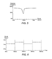
- the use of a single repetition interval between bursts may not benefit the detection of a pulse sequence which has the same interval as the repetition interval, also known as the chunk interval, since the periodicity of the two events would beat. It can be demonstrated that the detection probability may be affected by the chunk interval as shown in Figure 5 .
- the chunk interval can be modulated. For instance, the chunk interval can be changed between 2 or more values at intervals, so as to mitigate against regions of low detection probability for some values of detection interval.
- Figure 6 shows an example of an embodiment of the invention in which the chunk interval, that is to say repetition interval, is changed between 1.2ms and 1.5ms every 100ms.
- the detection probability for a 1.2ms Pulse Repetition Interval (PRI) radar type in the 1.2ms period would be approximately 50%, whereas it will be approximately 90% in the 1.5ms interval, and vice-versa for a 1.5ms radar PRI. Given this, the cumulative probability for both radar types is approximately 70% ((50% + 90%) / 2).
- the change of repetition intervals between activation periods can be chosen to match the radar detection needs.
- a token mechanism may be use to implement the chunking interval, as illustrated in Figure 7 .
- a token can be viewed as the right to transmit on the RF interface, and the transmitter is only permitted to hold one token at any given time.
- a data packet is received on the Ethernet interface, that is to say the data interface, it is added to a transmit queue and a decision is then made as to whether the transmit queue is allowed to be serviced for transmission. If the chunk interval has elapsed since the last time a token was added, then a token is added and the time recorded. If a token is available then the transmitter is permitted to service the transmit queue and the token is removed as shown in Figure 7 .
- the chunk interval that is to say repetition interval, may be changed between a first repetition interval and a second repetition interval, for example between 900us and 1100us, every 100ms for example.
- disabling of transmission until expiry of a wait period may be selected or not selected according to data loading conditions.
- the wait period may be disabled in dependence on data loading at the data interface. For example, the wait period may be disabled by setting the wait period to zero.
- the wait period may be enabled when the probability of detection of radar pulses is determined to be likely to be downgraded by transmissions from the terminal. In this way, latency may not be compromised during light loading.
- the chunk interval that is to say repetition interval
- the chunk interval can be adjusted to best match the radar type. If the chunk interval is relatively short, then the effect is to introduce dither to the radio transmissions. Depending on the radar detection required, this can improve the probability of detection with small impact on the latency.
Landscapes
- Engineering & Computer Science (AREA)
- Computer Networks & Wireless Communication (AREA)
- Signal Processing (AREA)
- Radar, Positioning & Navigation (AREA)
- Remote Sensing (AREA)
- Physics & Mathematics (AREA)
- General Physics & Mathematics (AREA)
- Quality & Reliability (AREA)
- Radar Systems Or Details Thereof (AREA)
Claims (17)
- Verfahren zum Übertragen von Datenpaketen von einem Terminal (2) eines Breitbandfunkkommunikationssystems, wobei das Terminal in der Lage ist, Radiosignale zu übertragen, die mit Radarpulsen interferieren könnten, wobei die Radarpulse mit einem oder mehreren Pulswiederholungsintervallen übertragen werden, wobei das Verfahren umfasst, für jeden einer Mehrzahl von Übertragungszyklen in einer Übertragungsperiode:Empfangen von Daten an einer Datenschnittstelle (6) des Terminals;Puffern der empfangenen Daten an dem Terminal;Ermöglichen einer Übertragung von Radiosignalen, die die empfangenen Daten umfassen, auf das Ablaufen eines entsprechenden Übertragungswiederholungsintervalls (38a, 38b) für den Zyklus hin, wobei das Übertragungswiederholungsintervall ein Intervall von dem Beginn einer vorherigen Übertragung ist, wobei die Übertragungswiederholungsintervalle kontrolliert werden, um einen Anteil der Übertragungsperiode, für den eine Übertragung an einem erlaubten Pulswiederholungsintervall des Radars auftreten kann, zu reduzieren;Prüfen auf das Vorhandensein von Radarpulsen während einer entsprechenden Warteperiode (30a, 30b) für jeden Zyklus, während das Terminal Radiosignale, die empfangene Datenpakete umfassen, nicht überträgt; undfalls Radarpulse vorhanden sind, Unterbinden der Übertragung von Radiosignalen, die mit den Radarpulsen interferieren könnten.
- Verfahren nach Anspruch 1, wobei das Unterbinden der Übertragung von Radiosignalen die Übertragung für eine definierte Periode unterbindet, um eine Bestätigung der Detektion von Radarpulsen zu erlauben.
- Verfahren nach Anspruch 1 oder Anspruch 2, wobei das Verfahren umfasst:Kontrollieren der Übertragungswiederholungsintervalle, um eine Wahrscheinlichkeit der Übertragung bei einem erlaubten Pulswiederholungsintervall des Radars zu reduzieren.
- Verfahren nach einem der vorangegangenen Ansprüche, wobei das Kontrollieren der Übertragungswiederholungsintervalle umfasst:Definieren erster und zweiter Übertragungsmuster, wobei das erste Übertragungsmuster dazu dient, eine Übertragung der empfangenen Daten periodisch auf das Ablaufen von jedem einer Mehrzahl von ersten Übertragungswiederholungsintervallen hin zu ermöglichen, und das zweite Übertragungsmuster dazu dient, eine Übertragung der empfangenen Daten periodisch auf das Ablaufen von jedem einer Mehrzahl von zweiten Übertragungswiederholungsintervallen hin zu ermöglichen.
- Verfahren nach Anspruch 4, wobei jedes der Mehrzahl von zweiten Übertragungswiederholungsintervallen zwischen 10 % und 40 % länger ist als jedes der Mehrzahl von ersten Übertragungswiederholungsintervallen.
- Verfahren nach Anspruch 5, wobei die ersten und zweiten Übertragungswiederholungsintervalle ausgewählt sind, innerhalb eines Bereichs von erlaubten Pulswiederholungsintervallen der Radarpulse zu sein.
- Verfahren nach einem der Ansprüche 4 bis 6, wobei die ersten und zweiten Übertragungsmuster jeweils für eine entsprechende Aktivierungsperiode aktiviert sind, wobei eine erste und eine zweite Aktivierungsperiode angepasst sind, alternierend aktiviert zu werden.
- Verfahren nach Anspruch 7, wobei die Aktivierungsperioden jeweils in dem Bereich von 20 Millisekunden bis zu 200 Millisekunden liegen.
- Verfahren nach einem der vorangegangenen Ansprüche, wobei das Kontrollieren des Übertragungswiederholungsintervalls umfasst:Einstellen jedes Übertragungswiederholungsintervalls so, dass es länger ist als ein gegebenes erlaubtes Radarpulswiederholungsintervall.
- Verfahren nach einem der vorangegangenen Ansprüche, wobei die Radarpulswiederholungsintervalle innerhalb eines Bereichs von 100 Mikrosekunden bis zu 10 Millisekunden liegen.
- Verfahren nach einem der vorangegangenen Ansprüche, wobei die Übertragungswiederholungsintervalle in dem Bereich von 1 Millisekunde bis zu 5 Millisekunden liegen.
- Verfahren nach Anspruch 7, wobei das erste Übertragungswiederholungsintervall in dem Bereich von 1 Millisekunde bis zu 1,3 Millisekunden liegt, das zweite Übertragungswiederholungsintervall in dem Bereich von 1,4 Millisekunden bis zu 1,8 Millisekunden liegt, und die ersten und zweiten Aktivierungsperioden in dem Bereich von 80 Millisekunden bis zu 130 Millisekunden liegen.
- Verfahren nach Anspruch 1 oder Anspruch 2, wobei das Kontrollieren der Übertragungswiederholungsintervalle ein Anwenden einer Schwankung auf die Dauer der Übertragungswiederholungsintervalle umfasst.
- Verfahren nach Anspruch 1, Anspruch 2 oder Anspruch 13, wobei das Kontrollieren der Übertragungswiederholungsintervalle ein Kontrollieren der Dauer von Übertragungswiederholungsintervallen entsprechend einem Pseudozufallsprozess umfasst.
- Verfahren nach einem der vorangegangenen Ansprüche, wobei das Verfahren ein Deaktivieren der Warteperiode in Abhängigkeit eines Ladens von Daten an der Datenschnittstelle umfasst.
- Terminal (2) zum Übertragen von Datenpaketen in einem Breitbandfunkkommunikationssystem, wobei das Terminal in der Lage ist, Radiosignale zu übertragen, die mit Radarpulsen interferieren können, wobei die Radarpulse mit einem oder mehreren Pulswiederholungsintervallen übertragen werden, wobei das Terminal umfasst:einen Datenempfänger, der angepasst ist, für jeden einer Mehrzahl von Übertragungszyklen, Daten an einer Datenschnittstelle (6) des Terminals zu empfangen;einen Puffer, der angepasst ist, für jeden der Mehrzahl von Übertragungszyklen, die empfangenen Daten an dem Terminal zu puffern; undeinen Kontroller, der ausgebildet ist zum:Ermöglichen einer Übertragung von Radiosignalen, die die empfangenen Daten umfassen, auf ein Ablaufen eines entsprechenden Übertragungswiederholungsintervalls (38a, 38b) für den Zyklus hin, wobei das Übertragungswiederholungsintervall ein Intervall von dem Beginn einer vorherigen Übertragung ist, wobei die Übertragungswiederholungsintervalle kontrolliert werden, um einen Anteil der Übertragungsperiode, für den eine Übertragung bei einem erlaubten Pulswiederholungsintervall des Radars auftreten kann, zu reduzieren;Prüfen auf das Vorhandensein von Radarpulsen während einer entsprechenden Warteperiode (30a, 30b) für jeden Zyklus, während das Terminal Radiosignale, die empfangene Datenpakete umfassen, nicht überträgt; undfalls Radarpulse vorhanden sind, Unterbinden der Übertragung von Radiosignalen, die mit den Radarpulsen interferieren könnten.
- Nicht-flüchtiges, computerlesbares Medium, das Anweisungen umfasst, die bewirken, dass ein Prozessor bewirkt, dass ein Terminal (2) ein Verfahren des Übertragens von Datenpaketen von einem Terminal eines Breitbandfunkkommunikationssystems ausführt, wobei das Terminal in der Lage ist, Radiosignale zu übertragen, die mit Radarpulsen interferieren könnten, wobei die Radarpulse mit einem oder mehreren Pulswiederholungsintervallen übertragen werden, wobei das Verfahren für jeden einer Mehrzahl von Übertragungszyklen in einer Übertragungsperiode umfasst:Empfangen von Daten an einer Datenschnittstelle (6) des Terminals;Puffern der empfangenen Daten an dem Terminal;Ermöglichen einer Übertragung von Radiosignalen, die die empfangenen Daten umfassen, auf das Ablaufen eines entsprechenden Übertragungswiederholungsintervalls (38a, 38b) für den Zyklus hin, wobei das Übertragungswiederholungsintervall ein Intervall von dem Beginn einer vorherigen Übertragung ist, wobei die Übertragungswiederholungsintervalle kontrolliert werden, um einen Anteil der Übertragungsperiode, für den eine Übertragung an einem erlaubten Pulswiederholungsintervall des Radars auftreten kann, zu reduzieren;Prüfen auf das Vorhandensein von Radarpulsen während einer entsprechenden Warteperiode (30a, 30b) für jeden Zyklus, während das Terminal Radiosignale, die empfangene Datenpakete umfassen, nicht überträgt; undfalls Radarpulse vorhanden sind, Unterbinden der Übertragung von Radiosignalen, die mit den Radarpulsen interferieren könnten.
Applications Claiming Priority (2)
| Application Number | Priority Date | Filing Date | Title |
|---|---|---|---|
| GBGB1200914.8A GB201200914D0 (en) | 2012-01-19 | 2012-01-19 | Transmission of data in a broadband radio communication system |
| PCT/GB2013/000026 WO2013108008A1 (en) | 2012-01-19 | 2013-01-21 | Transmission of data in a broadband radio communication system |
Publications (2)
| Publication Number | Publication Date |
|---|---|
| EP2805425A1 EP2805425A1 (de) | 2014-11-26 |
| EP2805425B1 true EP2805425B1 (de) | 2015-07-01 |
Family
ID=45814249
Family Applications (1)
| Application Number | Title | Priority Date | Filing Date |
|---|---|---|---|
| EP13702081.4A Active EP2805425B1 (de) | 2012-01-19 | 2013-01-21 | Datenübertragung in einem breitband-funkkommunikation system |
Country Status (4)
| Country | Link |
|---|---|
| US (1) | US8982831B2 (de) |
| EP (1) | EP2805425B1 (de) |
| GB (2) | GB201200914D0 (de) |
| WO (1) | WO2013108008A1 (de) |
Cited By (1)
| Publication number | Priority date | Publication date | Assignee | Title |
|---|---|---|---|---|
| US10114116B2 (en) * | 2014-08-19 | 2018-10-30 | Navico Holding As | Common burst for pulse compression radar |
Families Citing this family (8)
| Publication number | Priority date | Publication date | Assignee | Title |
|---|---|---|---|---|
| US20150063321A1 (en) * | 2013-09-04 | 2015-03-05 | Qualcomm Incorporated | Radar detection |
| US9713011B2 (en) | 2013-09-04 | 2017-07-18 | Qualcomm Incorporated | Managing radar detection in wireless network that uses frequency-division duplexing |
| US10222454B2 (en) * | 2014-08-19 | 2019-03-05 | Navico Holding As | Combining Reflected Signals |
| US9699663B1 (en) | 2015-02-20 | 2017-07-04 | Kathryn Jovancevic | Spectrum sharing system |
| US11012919B2 (en) * | 2017-12-07 | 2021-05-18 | Symbol Technologies, Llc | Methods and systems for mitigating connection impact on service infrastructure |
| US11930430B2 (en) | 2018-07-20 | 2024-03-12 | Doodle Labs (SG) PTE LTD. | Specialized wireless network arrangements for industrial applications |
| US12028796B2 (en) | 2019-03-12 | 2024-07-02 | Cypress Semiconductor Corporation | GPS-assisted collaborative and signaling-aided WLAN DFS operation |
| WO2022002403A1 (en) * | 2020-07-02 | 2022-01-06 | Nokia Technologies Oy | Jamming detection in wireless networks |
Family Cites Families (9)
| Publication number | Priority date | Publication date | Assignee | Title |
|---|---|---|---|---|
| US7496368B2 (en) * | 2001-04-03 | 2009-02-24 | Sharp Kabushiki Kaisha | Method and device for controlling frequency selection within a wireless communication system |
| EP1248477A1 (de) * | 2001-04-03 | 2002-10-09 | Telefonaktiebolaget L M Ericsson (Publ) | Methode und Gerät zur Steuerung einer dynamischen Frequenzauswahl in einem Mobilfunksystem |
| EP1449397B1 (de) * | 2001-11-30 | 2005-06-15 | Telefonaktiebolaget LM Ericsson (publ) | Störungsmessungen in einem drahtlosen kommunikationssystem |
| US6697013B2 (en) | 2001-12-06 | 2004-02-24 | Atheros Communications, Inc. | Radar detection and dynamic frequency selection for wireless local area networks |
| US7107032B2 (en) * | 2003-01-08 | 2006-09-12 | Mediatek Inc. | Radar detection method for radio local area networks |
| JP3828546B2 (ja) | 2004-01-26 | 2006-10-04 | 株式会社東芝 | 無線通信装置、無線通信方法及び無線通信プログラム |
| JP4349142B2 (ja) | 2004-02-09 | 2009-10-21 | ソニー株式会社 | 無線通信装置及び無線通信方法、並びにコンピュータ・プログラム |
| US9538388B2 (en) | 2006-05-12 | 2017-01-03 | Shared Spectrum Company | Method and system for dynamic spectrum access |
| TW201034498A (en) | 2009-03-03 | 2010-09-16 | Ralink Technology Corp | Method of handling radar signals for a wireless communication device |
-
2012
- 2012-01-19 GB GBGB1200914.8A patent/GB201200914D0/en not_active Ceased
-
2013
- 2013-01-21 WO PCT/GB2013/000026 patent/WO2013108008A1/en not_active Ceased
- 2013-01-21 EP EP13702081.4A patent/EP2805425B1/de active Active
- 2013-01-21 GB GB1301077.2A patent/GB2500300A/en not_active Withdrawn
-
2014
- 2014-07-18 US US14/335,137 patent/US8982831B2/en active Active
Cited By (2)
| Publication number | Priority date | Publication date | Assignee | Title |
|---|---|---|---|---|
| US10114116B2 (en) * | 2014-08-19 | 2018-10-30 | Navico Holding As | Common burst for pulse compression radar |
| US10120069B2 (en) | 2014-08-19 | 2018-11-06 | Navico Holding As | Multiple ranges for pulse compression radar |
Also Published As
| Publication number | Publication date |
|---|---|
| US8982831B2 (en) | 2015-03-17 |
| EP2805425A1 (de) | 2014-11-26 |
| GB201200914D0 (en) | 2012-02-29 |
| GB201301077D0 (en) | 2013-03-06 |
| US20140341137A1 (en) | 2014-11-20 |
| WO2013108008A1 (en) | 2013-07-25 |
| GB2500300A (en) | 2013-09-18 |
Similar Documents
| Publication | Publication Date | Title |
|---|---|---|
| EP2805425B1 (de) | Datenübertragung in einem breitband-funkkommunikation system | |
| US11888668B2 (en) | Communication device and integrated circuit | |
| RU2742208C1 (ru) | Конкретные шаблоны перескока для повторяющейся передачи и приема данных и способы для их формирования | |
| EP2983436B1 (de) | Mehrkanalige kommunikationsstation zur übermittlung einer mehrkanaligen ppdu sowie verfahren zur kollisionsreduzierung auf sekundärkanälen in drahtlosen mehrkanaligen netzwerken | |
| RU2643702C1 (ru) | Схема множественного доступа и структура сигнала для d2d коммуникаций | |
| US10361747B2 (en) | Hopping synchronization signals | |
| US20090067448A1 (en) | Contention-Based Communication | |
| US11258722B2 (en) | Telegram splitting transmission method for bidirectional networks | |
| KR20210011066A (ko) | 다중 뉴머롤로지 연산을 위한 랜덤 액세스 방법 | |
| US20130128927A1 (en) | System and method for detecting chirping radar pulses | |
| CN109379161B (zh) | 一种用于无人机的自适应干扰系统 | |
| US9439194B2 (en) | Method for robust real-time wireless industrial communication | |
| Kim et al. | Coexistence of full-duplex-based IEEE 802.15. 4 and IEEE 802.11 | |
| KR20230043959A (ko) | 포지셔닝 처리 방법, 장치 및 기기 | |
| US20140274174A1 (en) | Apparatus and method for wireless communication, having functions of different communication systems | |
| CN105103469A (zh) | 802.11n/ac使能设备中的802.11p信号的检测 | |
| KR20180029536A (ko) | 비 면허 대역을 사용하는 무선 통신 시스템에서 안테나 위상을 교정하는 방법 및 장치 | |
| TWI733338B (zh) | 通訊裝置與傳輸參數調整方法 | |
| EP4101220B1 (de) | Übertragung von daten im unlizenzierten spektrum | |
| CN113766451B (zh) | 缓和涉及多个系统的信道访问中的干扰 | |
| Chen et al. | Opportunistic spectrum access protocol for cognitive radio networks | |
| Bartolomeu et al. | Implementing the wireless FTT protocol: a feasibility analysis | |
| US20180042051A1 (en) | Channel access and fairness protocol for contention-based-access networks with biased detection | |
| Bartolomeu et al. | Channel capture in noisy wireless contention-based communication environments | |
| KR101675735B1 (ko) | 와이파이 영향에서 지그비의 공존을 위한 가이드 비지 톤 신호 제어 시스템 |
Legal Events
| Date | Code | Title | Description |
|---|---|---|---|
| PUAI | Public reference made under article 153(3) epc to a published international application that has entered the european phase |
Free format text: ORIGINAL CODE: 0009012 |
|
| 17P | Request for examination filed |
Effective date: 20140818 |
|
| AK | Designated contracting states |
Kind code of ref document: A1 Designated state(s): AL AT BE BG CH CY CZ DE DK EE ES FI FR GB GR HR HU IE IS IT LI LT LU LV MC MK MT NL NO PL PT RO RS SE SI SK SM TR |
|
| GRAP | Despatch of communication of intention to grant a patent |
Free format text: ORIGINAL CODE: EPIDOSNIGR1 |
|
| DAX | Request for extension of the european patent (deleted) | ||
| INTG | Intention to grant announced |
Effective date: 20150112 |
|
| GRAS | Grant fee paid |
Free format text: ORIGINAL CODE: EPIDOSNIGR3 |
|
| GRAA | (expected) grant |
Free format text: ORIGINAL CODE: 0009210 |
|
| AK | Designated contracting states |
Kind code of ref document: B1 Designated state(s): AL AT BE BG CH CY CZ DE DK EE ES FI FR GB GR HR HU IE IS IT LI LT LU LV MC MK MT NL NO PL PT RO RS SE SI SK SM TR |
|
| REG | Reference to a national code |
Ref country code: GB Ref legal event code: FG4D |
|
| REG | Reference to a national code |
Ref country code: AT Ref legal event code: REF Ref document number: 734487 Country of ref document: AT Kind code of ref document: T Effective date: 20150715 Ref country code: CH Ref legal event code: EP |
|
| REG | Reference to a national code |
Ref country code: IE Ref legal event code: FG4D |
|
| REG | Reference to a national code |
Ref country code: DE Ref legal event code: R096 Ref document number: 602013002142 Country of ref document: DE |
|
| REG | Reference to a national code |
Ref country code: AT Ref legal event code: MK05 Ref document number: 734487 Country of ref document: AT Kind code of ref document: T Effective date: 20150701 |
|
| REG | Reference to a national code |
Ref country code: NL Ref legal event code: MP Effective date: 20150701 |
|
| REG | Reference to a national code |
Ref country code: LT Ref legal event code: MG4D |
|
| PG25 | Lapsed in a contracting state [announced via postgrant information from national office to epo] |
Ref country code: LT Free format text: LAPSE BECAUSE OF FAILURE TO SUBMIT A TRANSLATION OF THE DESCRIPTION OR TO PAY THE FEE WITHIN THE PRESCRIBED TIME-LIMIT Effective date: 20150701 Ref country code: FI Free format text: LAPSE BECAUSE OF FAILURE TO SUBMIT A TRANSLATION OF THE DESCRIPTION OR TO PAY THE FEE WITHIN THE PRESCRIBED TIME-LIMIT Effective date: 20150701 Ref country code: NO Free format text: LAPSE BECAUSE OF FAILURE TO SUBMIT A TRANSLATION OF THE DESCRIPTION OR TO PAY THE FEE WITHIN THE PRESCRIBED TIME-LIMIT Effective date: 20151001 Ref country code: LV Free format text: LAPSE BECAUSE OF FAILURE TO SUBMIT A TRANSLATION OF THE DESCRIPTION OR TO PAY THE FEE WITHIN THE PRESCRIBED TIME-LIMIT Effective date: 20150701 Ref country code: GR Free format text: LAPSE BECAUSE OF FAILURE TO SUBMIT A TRANSLATION OF THE DESCRIPTION OR TO PAY THE FEE WITHIN THE PRESCRIBED TIME-LIMIT Effective date: 20151002 |
|
| REG | Reference to a national code |
Ref country code: FR Ref legal event code: PLFP Year of fee payment: 4 |
|
| PG25 | Lapsed in a contracting state [announced via postgrant information from national office to epo] |
Ref country code: PT Free format text: LAPSE BECAUSE OF FAILURE TO SUBMIT A TRANSLATION OF THE DESCRIPTION OR TO PAY THE FEE WITHIN THE PRESCRIBED TIME-LIMIT Effective date: 20151102 Ref country code: RS Free format text: LAPSE BECAUSE OF FAILURE TO SUBMIT A TRANSLATION OF THE DESCRIPTION OR TO PAY THE FEE WITHIN THE PRESCRIBED TIME-LIMIT Effective date: 20150701 Ref country code: IS Free format text: LAPSE BECAUSE OF FAILURE TO SUBMIT A TRANSLATION OF THE DESCRIPTION OR TO PAY THE FEE WITHIN THE PRESCRIBED TIME-LIMIT Effective date: 20151101 Ref country code: PL Free format text: LAPSE BECAUSE OF FAILURE TO SUBMIT A TRANSLATION OF THE DESCRIPTION OR TO PAY THE FEE WITHIN THE PRESCRIBED TIME-LIMIT Effective date: 20150701 Ref country code: AT Free format text: LAPSE BECAUSE OF FAILURE TO SUBMIT A TRANSLATION OF THE DESCRIPTION OR TO PAY THE FEE WITHIN THE PRESCRIBED TIME-LIMIT Effective date: 20150701 Ref country code: ES Free format text: LAPSE BECAUSE OF FAILURE TO SUBMIT A TRANSLATION OF THE DESCRIPTION OR TO PAY THE FEE WITHIN THE PRESCRIBED TIME-LIMIT Effective date: 20150701 Ref country code: SE Free format text: LAPSE BECAUSE OF FAILURE TO SUBMIT A TRANSLATION OF THE DESCRIPTION OR TO PAY THE FEE WITHIN THE PRESCRIBED TIME-LIMIT Effective date: 20150701 Ref country code: HR Free format text: LAPSE BECAUSE OF FAILURE TO SUBMIT A TRANSLATION OF THE DESCRIPTION OR TO PAY THE FEE WITHIN THE PRESCRIBED TIME-LIMIT Effective date: 20150701 |
|
| REG | Reference to a national code |
Ref country code: DE Ref legal event code: R097 Ref document number: 602013002142 Country of ref document: DE |
|
| PG25 | Lapsed in a contracting state [announced via postgrant information from national office to epo] |
Ref country code: SK Free format text: LAPSE BECAUSE OF FAILURE TO SUBMIT A TRANSLATION OF THE DESCRIPTION OR TO PAY THE FEE WITHIN THE PRESCRIBED TIME-LIMIT Effective date: 20150701 Ref country code: CZ Free format text: LAPSE BECAUSE OF FAILURE TO SUBMIT A TRANSLATION OF THE DESCRIPTION OR TO PAY THE FEE WITHIN THE PRESCRIBED TIME-LIMIT Effective date: 20150701 Ref country code: DK Free format text: LAPSE BECAUSE OF FAILURE TO SUBMIT A TRANSLATION OF THE DESCRIPTION OR TO PAY THE FEE WITHIN THE PRESCRIBED TIME-LIMIT Effective date: 20150701 Ref country code: IT Free format text: LAPSE BECAUSE OF FAILURE TO SUBMIT A TRANSLATION OF THE DESCRIPTION OR TO PAY THE FEE WITHIN THE PRESCRIBED TIME-LIMIT Effective date: 20150701 Ref country code: EE Free format text: LAPSE BECAUSE OF FAILURE TO SUBMIT A TRANSLATION OF THE DESCRIPTION OR TO PAY THE FEE WITHIN THE PRESCRIBED TIME-LIMIT Effective date: 20150701 |
|
| PLBE | No opposition filed within time limit |
Free format text: ORIGINAL CODE: 0009261 |
|
| STAA | Information on the status of an ep patent application or granted ep patent |
Free format text: STATUS: NO OPPOSITION FILED WITHIN TIME LIMIT |
|
| PG25 | Lapsed in a contracting state [announced via postgrant information from national office to epo] |
Ref country code: BE Free format text: LAPSE BECAUSE OF NON-PAYMENT OF DUE FEES Effective date: 20160131 Ref country code: RO Free format text: LAPSE BECAUSE OF FAILURE TO SUBMIT A TRANSLATION OF THE DESCRIPTION OR TO PAY THE FEE WITHIN THE PRESCRIBED TIME-LIMIT Effective date: 20150701 |
|
| 26N | No opposition filed |
Effective date: 20160404 |
|
| PG25 | Lapsed in a contracting state [announced via postgrant information from national office to epo] |
Ref country code: LU Free format text: LAPSE BECAUSE OF FAILURE TO SUBMIT A TRANSLATION OF THE DESCRIPTION OR TO PAY THE FEE WITHIN THE PRESCRIBED TIME-LIMIT Effective date: 20160121 Ref country code: SI Free format text: LAPSE BECAUSE OF FAILURE TO SUBMIT A TRANSLATION OF THE DESCRIPTION OR TO PAY THE FEE WITHIN THE PRESCRIBED TIME-LIMIT Effective date: 20150701 |
|
| REG | Reference to a national code |
Ref country code: CH Ref legal event code: PL |
|
| PG25 | Lapsed in a contracting state [announced via postgrant information from national office to epo] |
Ref country code: MC Free format text: LAPSE BECAUSE OF FAILURE TO SUBMIT A TRANSLATION OF THE DESCRIPTION OR TO PAY THE FEE WITHIN THE PRESCRIBED TIME-LIMIT Effective date: 20150701 |
|
| PG25 | Lapsed in a contracting state [announced via postgrant information from national office to epo] |
Ref country code: CH Free format text: LAPSE BECAUSE OF NON-PAYMENT OF DUE FEES Effective date: 20160131 Ref country code: LI Free format text: LAPSE BECAUSE OF NON-PAYMENT OF DUE FEES Effective date: 20160131 |
|
| REG | Reference to a national code |
Ref country code: IE Ref legal event code: MM4A |
|
| PG25 | Lapsed in a contracting state [announced via postgrant information from national office to epo] |
Ref country code: BE Free format text: LAPSE BECAUSE OF FAILURE TO SUBMIT A TRANSLATION OF THE DESCRIPTION OR TO PAY THE FEE WITHIN THE PRESCRIBED TIME-LIMIT Effective date: 20150701 |
|
| REG | Reference to a national code |
Ref country code: FR Ref legal event code: PLFP Year of fee payment: 5 |
|
| PG25 | Lapsed in a contracting state [announced via postgrant information from national office to epo] |
Ref country code: IE Free format text: LAPSE BECAUSE OF NON-PAYMENT OF DUE FEES Effective date: 20160121 |
|
| PG25 | Lapsed in a contracting state [announced via postgrant information from national office to epo] |
Ref country code: NL Free format text: LAPSE BECAUSE OF FAILURE TO SUBMIT A TRANSLATION OF THE DESCRIPTION OR TO PAY THE FEE WITHIN THE PRESCRIBED TIME-LIMIT Effective date: 20150701 |
|
| PG25 | Lapsed in a contracting state [announced via postgrant information from national office to epo] |
Ref country code: MT Free format text: LAPSE BECAUSE OF FAILURE TO SUBMIT A TRANSLATION OF THE DESCRIPTION OR TO PAY THE FEE WITHIN THE PRESCRIBED TIME-LIMIT Effective date: 20150701 |
|
| REG | Reference to a national code |
Ref country code: FR Ref legal event code: PLFP Year of fee payment: 6 |
|
| PG25 | Lapsed in a contracting state [announced via postgrant information from national office to epo] |
Ref country code: SM Free format text: LAPSE BECAUSE OF FAILURE TO SUBMIT A TRANSLATION OF THE DESCRIPTION OR TO PAY THE FEE WITHIN THE PRESCRIBED TIME-LIMIT Effective date: 20150701 Ref country code: HU Free format text: LAPSE BECAUSE OF FAILURE TO SUBMIT A TRANSLATION OF THE DESCRIPTION OR TO PAY THE FEE WITHIN THE PRESCRIBED TIME-LIMIT; INVALID AB INITIO Effective date: 20130121 |
|
| PG25 | Lapsed in a contracting state [announced via postgrant information from national office to epo] |
Ref country code: MK Free format text: LAPSE BECAUSE OF FAILURE TO SUBMIT A TRANSLATION OF THE DESCRIPTION OR TO PAY THE FEE WITHIN THE PRESCRIBED TIME-LIMIT Effective date: 20150701 Ref country code: CY Free format text: LAPSE BECAUSE OF FAILURE TO SUBMIT A TRANSLATION OF THE DESCRIPTION OR TO PAY THE FEE WITHIN THE PRESCRIBED TIME-LIMIT Effective date: 20150701 Ref country code: MT Free format text: LAPSE BECAUSE OF FAILURE TO SUBMIT A TRANSLATION OF THE DESCRIPTION OR TO PAY THE FEE WITHIN THE PRESCRIBED TIME-LIMIT Effective date: 20160131 |
|
| PG25 | Lapsed in a contracting state [announced via postgrant information from national office to epo] |
Ref country code: BG Free format text: LAPSE BECAUSE OF FAILURE TO SUBMIT A TRANSLATION OF THE DESCRIPTION OR TO PAY THE FEE WITHIN THE PRESCRIBED TIME-LIMIT Effective date: 20150701 |
|
| PG25 | Lapsed in a contracting state [announced via postgrant information from national office to epo] |
Ref country code: AL Free format text: LAPSE BECAUSE OF FAILURE TO SUBMIT A TRANSLATION OF THE DESCRIPTION OR TO PAY THE FEE WITHIN THE PRESCRIBED TIME-LIMIT Effective date: 20150701 Ref country code: TR Free format text: LAPSE BECAUSE OF FAILURE TO SUBMIT A TRANSLATION OF THE DESCRIPTION OR TO PAY THE FEE WITHIN THE PRESCRIBED TIME-LIMIT Effective date: 20150701 |
|
| PGFP | Annual fee paid to national office [announced via postgrant information from national office to epo] |
Ref country code: GB Payment date: 20260112 Year of fee payment: 14 |
|
| PGFP | Annual fee paid to national office [announced via postgrant information from national office to epo] |
Ref country code: DE Payment date: 20260113 Year of fee payment: 14 |
|
| PGFP | Annual fee paid to national office [announced via postgrant information from national office to epo] |
Ref country code: FR Payment date: 20260112 Year of fee payment: 14 |