EP2805376B1 - Resonatoranordnung und verfahren zum anregen eines resonators - Google Patents
Resonatoranordnung und verfahren zum anregen eines resonators Download PDFInfo
- Publication number
- EP2805376B1 EP2805376B1 EP12714981.3A EP12714981A EP2805376B1 EP 2805376 B1 EP2805376 B1 EP 2805376B1 EP 12714981 A EP12714981 A EP 12714981A EP 2805376 B1 EP2805376 B1 EP 2805376B1
- Authority
- EP
- European Patent Office
- Prior art keywords
- resonator
- frequency
- time
- excitation
- excited
- Prior art date
- Legal status (The legal status is an assumption and is not a legal conclusion. Google has not performed a legal analysis and makes no representation as to the accuracy of the status listed.)
- Not-in-force
Links
Images


Classifications
-
- H—ELECTRICITY
- H01—ELECTRIC ELEMENTS
- H01P—WAVEGUIDES; RESONATORS, LINES, OR OTHER DEVICES OF THE WAVEGUIDE TYPE
- H01P7/00—Resonators of the waveguide type
- H01P7/06—Cavity resonators
-
- H—ELECTRICITY
- H03—ELECTRONIC CIRCUITRY
- H03L—AUTOMATIC CONTROL, STARTING, SYNCHRONISATION, OR STABILISATION OF GENERATORS OF ELECTRONIC OSCILLATIONS OR PULSES
- H03L7/00—Automatic control of frequency or phase; Synchronisation
-
- H—ELECTRICITY
- H03—ELECTRONIC CIRCUITRY
- H03B—GENERATION OF OSCILLATIONS, DIRECTLY OR BY FREQUENCY-CHANGING, BY CIRCUITS EMPLOYING ACTIVE ELEMENTS WHICH OPERATE IN A NON-SWITCHING MANNER; GENERATION OF NOISE BY SUCH CIRCUITS
- H03B1/00—Details
- H03B1/02—Structural details of power oscillators, e.g. for heating
-
- H—ELECTRICITY
- H03—ELECTRONIC CIRCUITRY
- H03B—GENERATION OF OSCILLATIONS, DIRECTLY OR BY FREQUENCY-CHANGING, BY CIRCUITS EMPLOYING ACTIVE ELEMENTS WHICH OPERATE IN A NON-SWITCHING MANNER; GENERATION OF NOISE BY SUCH CIRCUITS
- H03B21/00—Generation of oscillations by combining unmodulated signals of different frequencies
- H03B21/01—Generation of oscillations by combining unmodulated signals of different frequencies by beating unmodulated signals of different frequencies
-
- H—ELECTRICITY
- H03—ELECTRONIC CIRCUITRY
- H03B—GENERATION OF OSCILLATIONS, DIRECTLY OR BY FREQUENCY-CHANGING, BY CIRCUITS EMPLOYING ACTIVE ELEMENTS WHICH OPERATE IN A NON-SWITCHING MANNER; GENERATION OF NOISE BY SUCH CIRCUITS
- H03B5/00—Generation of oscillations using amplifier with regenerative feedback from output to input
- H03B5/18—Generation of oscillations using amplifier with regenerative feedback from output to input with frequency-determining element comprising distributed inductance and capacitance
- H03B5/1817—Generation of oscillations using amplifier with regenerative feedback from output to input with frequency-determining element comprising distributed inductance and capacitance the frequency-determining element being a cavity resonator
-
- H—ELECTRICITY
- H05—ELECTRIC TECHNIQUES NOT OTHERWISE PROVIDED FOR
- H05H—PLASMA TECHNIQUE; PRODUCTION OF ACCELERATED ELECTRICALLY-CHARGED PARTICLES OR OF NEUTRONS; PRODUCTION OR ACCELERATION OF NEUTRAL MOLECULAR OR ATOMIC BEAMS
- H05H7/00—Details of devices of the types covered by groups H05H9/00, H05H11/00, H05H13/00
- H05H7/02—Circuits or systems for supplying or feeding radio-frequency energy
-
- H—ELECTRICITY
- H05—ELECTRIC TECHNIQUES NOT OTHERWISE PROVIDED FOR
- H05H—PLASMA TECHNIQUE; PRODUCTION OF ACCELERATED ELECTRICALLY-CHARGED PARTICLES OR OF NEUTRONS; PRODUCTION OR ACCELERATION OF NEUTRAL MOLECULAR OR ATOMIC BEAMS
- H05H7/00—Details of devices of the types covered by groups H05H9/00, H05H11/00, H05H13/00
- H05H7/14—Vacuum chambers
- H05H7/18—Cavities; Resonators
-
- H—ELECTRICITY
- H05—ELECTRIC TECHNIQUES NOT OTHERWISE PROVIDED FOR
- H05H—PLASMA TECHNIQUE; PRODUCTION OF ACCELERATED ELECTRICALLY-CHARGED PARTICLES OR OF NEUTRONS; PRODUCTION OR ACCELERATION OF NEUTRAL MOLECULAR OR ATOMIC BEAMS
- H05H7/00—Details of devices of the types covered by groups H05H9/00, H05H11/00, H05H13/00
- H05H7/02—Circuits or systems for supplying or feeding radio-frequency energy
- H05H2007/025—Radiofrequency systems
Definitions
- Resonator arrangement and method for exciting a resonator The present invention relates to a method for exciting a resonator according to patent claim 1, as well as to a resonator arrangement comprising a resonator and a starting device according to patent claim 7.
- Resonators ie oscillatory systems, exist in many variants.
- Resonators may be formed, for example, as RF cavities in which electromagnetic oscillations can be excited. It is known to use such RF cavities in particle accelerators for accelerating electrically charged particles.
- the object of the present invention is to provide an improved method for exciting a resonator. This object is achieved by a method having the features of claim 1.
- a further object of the present invention is to provide an improved resonator arrangement with a resonator and an exciting device. This object is achieved by a resonator arrangement with the features of claim 7. Preferred developments are specified in the dependent claims.
- the resonator is excited during a first period of time at a first frequency which differs from the resonant frequency by a first frequency difference.
- the resonator is excited at a second frequency that differs from the resonant frequency by a second frequency difference.
- the first frequency difference and the second frequency difference have different signs.
- the amounts of the first frequency difference and the second frequency difference differ by less than 10% of the larger amount from each other.
- the first frequency and the second frequency are as symmetrical as possible about the resonance frequency.
- the method thereby allows to regulate the power fed into the resonator without varying the amplitude of the excitation. As a result, the method is technically advantageously implement without much effort.
- first time periods and second time periods follow one another repeatedly.
- the first time periods and the second time periods can then be dimensioned very short in each case, as a result of which the phase shifts of the resonator oscillation caused by the excitation of the resonator with the first frequency and the second frequency are brought out particularly effectively.
- first period and the second period have the same length.
- This also supports a particularly effective determination of phase shifts of the resonator oscillation.
- the resonator is excited during the first time period and the second time period with a constant excitation amplitude.
- the method can then be implemented without regulation of the excitation amplitude.
- the resonator is excited at a resonant frequency during a further period of time.
- the power supplied to the resonator during the further period then increases.
- the resonator is excited during the first period, the second period and the further period of constant excitation amplitude.
- an excitation device can then be used to excite the resonator, in which an adjustability of the excitation amplitude does not necessarily have to be possible.
- a resonator arrangement according to the invention comprises a resonator and an exciting device for exciting a vibration of the resonator.
- the starter device is formed, to carry out a method of the aforementioned type.
- the starting device can advantageously be formed simply and with high efficiency.
- the oscillation is an electromagnetic oscillation.
- the resonator arrangement can then be used for many technical purposes.
- the resonator is designed as an RF cavity.
- RF cavities can be used for many technical purposes.
- the resonator is a resonator of a particle accelerator.
- the resonator of the resonator arrangement can then be used to accelerate electrically charged particles. Because of the enormous energy consumption of particle accelerators, an embodiment of the exciting device with high efficiency which is made possible with this resonator arrangement is advantageously particularly favorable.
- the starting device has a solid-state switch.
- the use of solid-state circuits allows a compact, cost-effective and energy-efficient design of the exciting device.
- FIG. 1 shows in a schematic representation in a graph an amplitude-frequency response 100 of a resonator.
- each resonator has a comparable amplitude-frequency response.
- the resonator can be, for example, an RF cavity in which an electromagnetic oscillation can be excited.
- an excitation frequency 101 is plotted.
- the excitation frequency 101 indicates a frequency with which a resonator oscillation of the resonator is excited from the outside.
- a vibration amplitude 102 is plotted on a vertical axis of the graph of FIG. 1 .
- the oscillation amplitude 102 indicates an amplitude of the resonator oscillation of the resonator and thus represents a measure of an energy stored in the resonator oscillation.
- the amplitude-frequency response 100 of FIG. 1 indicates the amplitude of the resonator oscillation which occurs when the resonator is excited at a specific excitation frequency 101.
- the amplitude-frequency response 100 gives the FIG. 1 the energy which is fed into the resonator as a function of the excitation frequency 101 of the external excitation by the external excitation.
- the amplitude-frequency response 100 has a maximum amplitude 140 at a resonance frequency 110 of the resonator.
- the amplitude excited in the resonator drops.
- the excited resonator has only a reduced amplitude 150.
- the resonator oscillation also has the reduced amplitude 150.
- the drop in the amplitude-frequency response 100 outside the resonance frequency 110 is the steeper, the higher the quality of the resonator.
- the amplitudes at the reduced frequency 120 and at the increased frequency 130 could also be different.
- the reduced frequency 120 differs from the resonant frequency 110 by a first frequency difference 125.
- the increased frequency 130 differs from the resonant frequency 110 by a second frequency difference 135.
- the first frequency difference 125 and the second frequency difference 135 have different signs. Preferably, however, the first frequency difference 125 and the second frequency difference 135 have approximately equal amounts. Then, the resonance frequency 110 is centered between the reduced frequency 120 and the increased frequency 130.
- a resonator oscillation with the maximum amplitude 140 sets in.
- the energy supplied to the resonator is maximum in this case.
- a resonator oscillation having the reduced amplitude 150 sets in. In this case, so less energy is fed into the resonator by the external excitation.
- the excitation frequency 101 with which the Resonator is excited, the energy fed into the resonator can be varied.
- FIG. 2 shows a schematic representation of a graph of a phase angle 200 between the outer excitation of the resonator and the resonator in the resonator vibration.
- the excitation frequency 101 of the external excitation is plotted on a horizontal axis.
- a phase shift 201 is plotted between the outer excitation and the resonator oscillation.
- a resonant phase position 210 is established between the external excitation and the resonator oscillation.
- the resonant phase position 210 may be, for example, a phase shift of 90 ° between the excitation and the resonator oscillation.
- the phase shift 201 between excitation and resonator oscillation changes.
- a first phase position 220 arises and, with excitation of the resonator with the increased frequency 130, a second phase position 230. This is usually undesirable. It is desired that the phase shift 201 between the external excitation and the resonator oscillation remains at the resonant phase position 210.
- the reduced frequency 120 and the increased frequency 130 are selected such that the first phase position 220 differs from the resonant phase position 210 by a first phase position change 225, and the second phase position 230 differs from the resonant phase position 210 by a second phase position Phase change 235 differs.
- the first phase position change 225 and the second phase position change 235 have different signs, but approximately equal amounts.
- the reduced frequency 120 and the increased frequency 130 are thus selected such that the first phase position 220 which arises when the reduced frequency 120 is excited and the phase position 230 which is set when excited with the increased frequency 130 are arranged as symmetrically as possible about the resonant phase position 210 , the first phase position change 225 and the second phase position change 235 thus have identical amounts as possible. Less important is whether the same reduced amplitude 150 occurs when excited with the reduced frequency 120 and when excited with the increased frequency 130. It is not critical if a different oscillation amplitude 102 occurs at the reduced frequency 120 than at the increased frequency 130.
- the first frequency difference 125 and the second frequency difference 135 thus have approximately equal amounts.
- the amounts of the first frequency difference 125 and the second frequency difference 135 differ by less than 10% of the larger amount.
- the amounts of the first frequency difference 125 and the second frequency difference 135 differed by a still significantly smaller fraction, for example by only 5% or 1% of the larger amount.
- the resulting phase position changes 225, 235 mutually compensate each other. This compensation works the better the faster the intervals of the excitation with the reduced frequency 120 and with the increased frequency 130 follow one another. This can be achieved, for example, by controlling the excitation frequency in a controlled manner with a jitter.
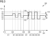
- FIG. 3 shows a schematic excitation frequency curve 300 through which a power control of a resonator, without changing an amplitude of the excitation of the resonator.
- a time 301 is plotted on a horizontal axis of the graph of the FIG. 3 .
- the excitation frequency 101 is applied, with which the resonator is excited.
- FIG. 4 shows in a schematic graph, an amplitude curve 400 of the oscillation amplitude of the resonator, which during the excitation of the resonator according to the excitation frequency curve 300 of the FIG. 3 established.
- the time 301 is also plotted.
- the oscillation amplitude 102 of the resonator oscillation is shown on the vertical axis of the graph.
- the resonator with the resonator frequency 110 is excited.
- the maximum amplitude 140 of the resonator occurs.
- the energy fed into the resonator is to be reduced.
- the time between the second time 320 and the third time 330 is subdivided into a second time period 321, a third time period 322, a fourth time period 323 and a fifth time period 324.
- the periods 321, 322, 323, 324 preferably each last about the same length.
- the second period 321 and the fourth period 323, the resonator with the increased frequency 130 is excited.
- the reduced frequency resonator 120 is excited. Consequently, a resonator oscillation occurs between the second time 320 and the third time 330 in the resonator with the reduced amplitude 150.
- the power fed into the resonator is thus less than between the first time 310 and the second time 320. Since the resonator between the second time 320 and the third time 330 always alternately with the increased frequency 130 and the reduced frequency 120 is excited, the resulting phase position changes 225, 235 average out between the excitation and the resonator oscillation. Thus, the phase shift 201 between the excitation and the resonator oscillation remains at the resonant phase position 210 in the time average.
- the resonator is excited between the second time 320 and the third time 330 only during two periods 321, 323 at the increased frequency 130 and during two periods 322, 324 at the reduced frequency 120.
- the time interval between the second time 320 and the third time 330 is preferably subdivided into substantially more individual time periods with different excitation frequency 101.
- the reduced frequency 120 and the increased frequency 130 thus alternate much more frequently.
- the resonator is excited again at the resonance frequency 110.
- the resonator oscillation again assumes the maximum amplitude 140 between the third time 330 and the fourth time 340.
- the power fed into the resonator is thus maximum again.
- the power fed into the resonator is to be reduced even further than between the second time 320 and the third time 330. This is achieved by switching the resonator between the fourth time 340 and the fifth time 350 alternately with a second reduced frequency 121 and a second increased frequency 131 is excited.
- the second reduced frequency 121 differs from the resonance frequency 110 by a third frequency difference 126.
- the second increased frequency 131 differs from the resonant frequency 110 of the resonator by a fourth frequency difference 136.
- the third frequency difference 126 and the fourth frequency difference 136 have different signs and approximately matching amounts. However, the magnitude of the third frequency difference 126 is greater than the magnitude of the first frequency difference 125. The magnitude of the fourth frequency difference 136 is greater than the magnitude of the second frequency difference 135. Off FIG. 1 It can be seen that, as a result of the frequency differences 126, 136 increased in relation to the frequency differences 125, 135, the power fed into the resonator when excited with the second boosted frequency 131 and the second reduced frequency 121 is greater than that of the reduced frequency resonator 120 and increased Frequency 130 is additionally reduced.
- the time interval between the fourth time 340 and the fifth time 350 is divided into a seventh time period 341, an eighth time period 342, a ninth time period 343, and a tenth time period 344.
- the time interval between the fourth time 340 and the fifth time 350 could also be divided into a much larger number of individual time periods.
- the resonator is excited at the second increased frequency 131.
- the eighth period 342 and the tenth period 344 the second reduced frequency resonator 121 is excited.
- an oscillation with a second reduced amplitude 151 occurs between the fourth time 340 and the fifth time 350 in the resonator.
- the second reduced amplitude 151 is lower than the maximum amplitude 140 and also lower than the reduced amplitude 150.
- the power fed into the resonator between the fourth time 340 and the fifth time 350 is lower than during any other time between the first time 310 and the fourth time 340.
- the second reduced frequency 121 and the second increased frequency 131 are thus arranged approximately symmetrically about the resonance frequency 110, which compensate by the excitation of the resonator with the second reduced Frequency 121 and the second increased frequency 131 adjusting phase changes between the excitation and the resonator oscillation in the time average between the fourth time 340 and the fifth time point 350th
- the excitation amplitude with which the resonator is excited must not be varied in this method. Instead, the frequency at which the resonator is excited is varied. If the resonator is excited with its resonance frequency, then the power fed into the resonator is maximum. If the resonator is excited at a frequency different from the resonance frequency, the power fed into the resonator is reduced, although a phase shift between the excitation and the resonator oscillation also changes. However, if the resonator is excited rapidly alternately at two different frequencies, which are approximately symmetrical about the resonance frequency, then the resulting phase shifts average out.
- the variation of the excitation frequency can be done by applying the excitation frequency with jitter.
- FIG. 5 shows a schematic representation of an exemplary resonator 500, which is suitable for carrying out the method described.
- the resonator arrangement 500 may be, for example, a resonator arrangement in a particle accelerator for accelerating electrically charged particles.
- the resonator arrangement 500 comprises a resonator 510.
- the resonator 510 is designed as an RF cavity in the illustrated example.
- the resonator 510 is in the example shown a so-called pillbox resonator with a cylindrical shape.
- a lateral surface of the cylindrical resonator 510 is formed by a metallic resonator wall 520.
- the Resonatorwandung 520 has a circumferential slot 530, in which an electrically insulating material is arranged.
- an excitation device 540 is arranged, which preferably has a solid-state switch.
- a high-frequency electrical current flow can be induced between the two sections of the resonator wall 520 delimited from one another by the slot 530, whereby a resonator oscillation in the resonator 510 is excited.
- the excitation device 540 is designed to excite the resonator 510 according to the method described above.
- the starting device 540 In order to control the power fed into the resonator 510, the starting device 540 thus varies the frequency of the voltage applied across the slot 530 of the resonator wall 520.
- the output amplitude of the starting device 540 remains constant. This has the advantage that the starting device 540 can be formed with a fixed amplifier chain, which does not have to be variable. This advantageously results in a simple construction of the starting device 540. In addition, this makes it possible to form the exciting device 540 advantageously with high efficiency.
Applications Claiming Priority (1)
| Application Number | Priority Date | Filing Date | Title |
|---|---|---|---|
| PCT/EP2012/054995 WO2013139389A1 (de) | 2012-03-21 | 2012-03-21 | Resonatoranordnung und verfahren zum anregen eines resonators |
Publications (2)
| Publication Number | Publication Date |
|---|---|
| EP2805376A1 EP2805376A1 (de) | 2014-11-26 |
| EP2805376B1 true EP2805376B1 (de) | 2016-12-14 |
Family
ID=45976286
Family Applications (1)
| Application Number | Title | Priority Date | Filing Date |
|---|---|---|---|
| EP12714981.3A Not-in-force EP2805376B1 (de) | 2012-03-21 | 2012-03-21 | Resonatoranordnung und verfahren zum anregen eines resonators |
Country Status (9)
| Country | Link |
|---|---|
| US (1) | US9246495B2 (ko) |
| EP (1) | EP2805376B1 (ko) |
| JP (1) | JP5989222B2 (ko) |
| KR (1) | KR101916349B1 (ko) |
| CN (1) | CN104247145B (ko) |
| IN (1) | IN2014DN07319A (ko) |
| PL (1) | PL2805376T3 (ko) |
| RU (1) | RU2586410C2 (ko) |
| WO (1) | WO2013139389A1 (ko) |
Families Citing this family (4)
| Publication number | Priority date | Publication date | Assignee | Title |
|---|---|---|---|---|
| DE112016003662A5 (de) | 2015-08-11 | 2018-06-14 | Continental Teves Ag & Co. Ohg | Vorrichtung zum Messen einer Messgröße |
| DE102015215331A1 (de) * | 2015-08-11 | 2017-02-16 | Continental Teves Ag & Co. Ohg | Elektronische Steuerungseinheit |
| DE102016202403A1 (de) | 2016-02-17 | 2017-08-17 | Continental Teves Ag & Co. Ohg | Sensor |
| DE102016202402A1 (de) | 2016-02-17 | 2017-08-17 | Continental Teves Ag & Co. Ohg | Sensor |
Citations (1)
| Publication number | Priority date | Publication date | Assignee | Title |
|---|---|---|---|---|
| US2790905A (en) * | 1953-06-09 | 1957-04-30 | Marconi Wireless Telegraph Co | Automatic frequency control |
Family Cites Families (14)
| Publication number | Priority date | Publication date | Assignee | Title |
|---|---|---|---|---|
| US2887580A (en) | 1957-04-26 | 1959-05-19 | Gen Electric | Variable output control for linear accelerators |
| SU536628A1 (ru) * | 1975-06-13 | 1976-11-25 | Объединенный Институт Ядерных Исследований | Устройство возбуждени резонатора линейного ускорител ионов |
| FR2451061A1 (fr) * | 1979-03-09 | 1980-10-03 | Ebauches Sa | Maser passif |
| US4314209A (en) * | 1980-04-21 | 1982-02-02 | Hughes Aircraft Company | Q-Enhanced resonance-stabilized maser |
| SU876045A1 (ru) * | 1980-06-13 | 1987-09-30 | Предприятие П/Я М-5631 | Система возбуждени резонатора ускорител |
| SU1042598A1 (ru) * | 1981-07-30 | 1986-08-23 | Предприятие П/Я А-7094 | Резонансна ускор юща система |
| SU1143309A2 (ru) * | 1983-02-04 | 1986-01-07 | Московский Ордена Трудового Красного Знамени Инженерно-Физический Институт | Ускор юща система |
| JP2673365B2 (ja) * | 1989-02-23 | 1997-11-05 | アンリツ株式会社 | 空胴共振器の共振周波数制御装置 |
| JP2995131B2 (ja) * | 1993-05-28 | 1999-12-27 | アンリツ株式会社 | 空胴共振器の高安定共振周波数制御装置 |
| FR2895170B1 (fr) * | 2005-12-15 | 2008-03-07 | Renault Sas | Optimisation de la frequence d'excitation d'un resonateur |
| US20080068112A1 (en) * | 2006-09-14 | 2008-03-20 | Yu David U L | Rod-loaded radiofrequency cavities and couplers |
| JP5044663B2 (ja) * | 2007-09-14 | 2012-10-10 | シュルンベルジェ ホールディングス リミテッド | 粒子加速装置 |
| US8183801B2 (en) | 2008-08-12 | 2012-05-22 | Varian Medical Systems, Inc. | Interlaced multi-energy radiation sources |
| US8311187B2 (en) * | 2010-01-29 | 2012-11-13 | Accuray, Inc. | Magnetron powered linear accelerator for interleaved multi-energy operation |
-
2012
- 2012-03-21 JP JP2015500779A patent/JP5989222B2/ja not_active Expired - Fee Related
- 2012-03-21 WO PCT/EP2012/054995 patent/WO2013139389A1/de active Application Filing
- 2012-03-21 US US14/386,047 patent/US9246495B2/en not_active Expired - Fee Related
- 2012-03-21 PL PL12714981T patent/PL2805376T3/pl unknown
- 2012-03-21 RU RU2014142269/28A patent/RU2586410C2/ru not_active IP Right Cessation
- 2012-03-21 KR KR1020147029493A patent/KR101916349B1/ko active IP Right Grant
- 2012-03-21 CN CN201280071644.9A patent/CN104247145B/zh not_active Expired - Fee Related
- 2012-03-21 EP EP12714981.3A patent/EP2805376B1/de not_active Not-in-force
- 2012-03-21 IN IN7319DEN2014 patent/IN2014DN07319A/en unknown
Patent Citations (1)
| Publication number | Priority date | Publication date | Assignee | Title |
|---|---|---|---|---|
| US2790905A (en) * | 1953-06-09 | 1957-04-30 | Marconi Wireless Telegraph Co | Automatic frequency control |
Also Published As
| Publication number | Publication date |
|---|---|
| WO2013139389A1 (de) | 2013-09-26 |
| CN104247145B (zh) | 2016-10-26 |
| JP5989222B2 (ja) | 2016-09-07 |
| US9246495B2 (en) | 2016-01-26 |
| KR101916349B1 (ko) | 2018-11-07 |
| PL2805376T3 (pl) | 2017-06-30 |
| IN2014DN07319A (ko) | 2015-04-24 |
| CN104247145A (zh) | 2014-12-24 |
| US20150048893A1 (en) | 2015-02-19 |
| KR20140139028A (ko) | 2014-12-04 |
| EP2805376A1 (de) | 2014-11-26 |
| RU2014142269A (ru) | 2016-05-20 |
| RU2586410C2 (ru) | 2016-06-10 |
| JP2015516724A (ja) | 2015-06-11 |
Similar Documents
| Publication | Publication Date | Title |
|---|---|---|
| EP1797490B1 (de) | Verfahren und vorrichtung zur ermittlung eines mit einer ditherfrequenz überlagerten pwm-signals zur steuerung eines magnetventils | |
| EP2805376B1 (de) | Resonatoranordnung und verfahren zum anregen eines resonators | |
| DE102014219016B4 (de) | Verfahren zum Steuern eines Stehwellenbeschleunigers | |
| DE102014103414B3 (de) | Verfahren zum Steuern eines Korona-Zündsystem eines taktweise arbeitenden Verbrennungsmotors | |
| DE748787C (de) | Als Vierpol geschaltete Laufzeitspule | |
| DE809328C (de) | Hochfrequenzschwingungserzeuger vom Reflexionstyp | |
| EP2684249B1 (de) | Hf-generator | |
| DE102016101660A1 (de) | Verfahren zur Anregung von piezoelektrischen Wandlern und Schallerzeugungsanordnung | |
| DE102013112316A1 (de) | Piezoelektrischer Transformator und Gegenelektrode | |
| DE19850447B4 (de) | Nicht-linearer Dispersions-Impulsgenerator | |
| WO2016184965A1 (de) | Bandpassfilter mit einem hohlraumresonator und verfahren zum betreiben, einstellen oder herstellen eines solchen bandpassfilters | |
| DE19821382A1 (de) | Verfahren zum Abgleichen der Resonanzfrequenz eines Ringresonators | |
| DE3401087A1 (de) | Elektronenentladungs-oszillator mit gekreuzten feldern | |
| EP2991158B1 (de) | Generisches kanalfilter | |
| DE2214252C3 (de) | Bandfilter fur elektrische Schwingungen | |
| DE1181342B (de) | Linear-Ionenbeschleuniger | |
| WO2018095921A1 (de) | Treiberschaltung, insbesondere für eine pockelszelle und verfahren zum betrieb einer treiberschaltung | |
| DE102021117830A1 (de) | Hohlleitereinrichtung | |
| DE102010044113A1 (de) | HF-Kavität und Teilchenbeschleuniger mit HF-Kavität | |
| DE102004023750B4 (de) | Verfahren zum Betreiben eines Gaslasers mit einer getakteten Hochfrequenzspannung und nach diesem Verfahren betriebener Gaslaser | |
| DE1276238B (de) | Mechanisches Filter | |
| EP3095192A1 (de) | Verfahren zur regelung von schaltflanken für geschaltete endstufen, regelungsvorrichtung und endstufe | |
| WO2019091845A1 (de) | Element zur konversion zwischen mindestens einer linear polarisierten elektromagnetischen welle und mindestens einer elliptisch polarisierten elektromagnetischen welle in einem hohlleiter | |
| DE102009034426A1 (de) | Spulenmatte zur Erzeugung eines wandernden Magnetfeldes | |
| EP2885837B1 (de) | Vorrichtung zum einkoppeln von hf-leistung in einen wellenleiter |
Legal Events
| Date | Code | Title | Description |
|---|---|---|---|
| PUAI | Public reference made under article 153(3) epc to a published international application that has entered the european phase |
Free format text: ORIGINAL CODE: 0009012 |
|
| 17P | Request for examination filed |
Effective date: 20140820 |
|
| AK | Designated contracting states |
Kind code of ref document: A1 Designated state(s): AL AT BE BG CH CY CZ DE DK EE ES FI FR GB GR HR HU IE IS IT LI LT LU LV MC MK MT NL NO PL PT RO RS SE SI SK SM TR |
|
| DAX | Request for extension of the european patent (deleted) | ||
| 17Q | First examination report despatched |
Effective date: 20151116 |
|
| GRAP | Despatch of communication of intention to grant a patent |
Free format text: ORIGINAL CODE: EPIDOSNIGR1 |
|
| RIC1 | Information provided on ipc code assigned before grant |
Ipc: H05H 7/02 20060101ALI20160607BHEP Ipc: H01P 7/06 20060101AFI20160607BHEP Ipc: H05H 7/18 20060101ALI20160607BHEP |
|
| INTG | Intention to grant announced |
Effective date: 20160705 |
|
| GRAS | Grant fee paid |
Free format text: ORIGINAL CODE: EPIDOSNIGR3 |
|
| GRAA | (expected) grant |
Free format text: ORIGINAL CODE: 0009210 |
|
| AK | Designated contracting states |
Kind code of ref document: B1 Designated state(s): AL AT BE BG CH CY CZ DE DK EE ES FI FR GB GR HR HU IE IS IT LI LT LU LV MC MK MT NL NO PL PT RO RS SE SI SK SM TR |
|
| REG | Reference to a national code |
Ref country code: GB Ref legal event code: FG4D Free format text: NOT ENGLISH |
|
| REG | Reference to a national code |
Ref country code: CH Ref legal event code: EP |
|
| REG | Reference to a national code |
Ref country code: IE Ref legal event code: FG4D Free format text: LANGUAGE OF EP DOCUMENT: GERMAN |
|
| REG | Reference to a national code |
Ref country code: AT Ref legal event code: REF Ref document number: 854333 Country of ref document: AT Kind code of ref document: T Effective date: 20170115 |
|
| REG | Reference to a national code |
Ref country code: DE Ref legal event code: R096 Ref document number: 502012009022 Country of ref document: DE |
|
| PG25 | Lapsed in a contracting state [announced via postgrant information from national office to epo] |
Ref country code: LV Free format text: LAPSE BECAUSE OF FAILURE TO SUBMIT A TRANSLATION OF THE DESCRIPTION OR TO PAY THE FEE WITHIN THE PRESCRIBED TIME-LIMIT Effective date: 20161214 |
|
| REG | Reference to a national code |
Ref country code: FR Ref legal event code: PLFP Year of fee payment: 6 |
|
| REG | Reference to a national code |
Ref country code: LT Ref legal event code: MG4D |
|
| REG | Reference to a national code |
Ref country code: NL Ref legal event code: MP Effective date: 20161214 |
|
| PG25 | Lapsed in a contracting state [announced via postgrant information from national office to epo] |
Ref country code: LT Free format text: LAPSE BECAUSE OF FAILURE TO SUBMIT A TRANSLATION OF THE DESCRIPTION OR TO PAY THE FEE WITHIN THE PRESCRIBED TIME-LIMIT Effective date: 20161214 Ref country code: GR Free format text: LAPSE BECAUSE OF FAILURE TO SUBMIT A TRANSLATION OF THE DESCRIPTION OR TO PAY THE FEE WITHIN THE PRESCRIBED TIME-LIMIT Effective date: 20170315 Ref country code: NO Free format text: LAPSE BECAUSE OF FAILURE TO SUBMIT A TRANSLATION OF THE DESCRIPTION OR TO PAY THE FEE WITHIN THE PRESCRIBED TIME-LIMIT Effective date: 20170314 Ref country code: SE Free format text: LAPSE BECAUSE OF FAILURE TO SUBMIT A TRANSLATION OF THE DESCRIPTION OR TO PAY THE FEE WITHIN THE PRESCRIBED TIME-LIMIT Effective date: 20161214 |
|
| PG25 | Lapsed in a contracting state [announced via postgrant information from national office to epo] |
Ref country code: HR Free format text: LAPSE BECAUSE OF FAILURE TO SUBMIT A TRANSLATION OF THE DESCRIPTION OR TO PAY THE FEE WITHIN THE PRESCRIBED TIME-LIMIT Effective date: 20161214 Ref country code: FI Free format text: LAPSE BECAUSE OF FAILURE TO SUBMIT A TRANSLATION OF THE DESCRIPTION OR TO PAY THE FEE WITHIN THE PRESCRIBED TIME-LIMIT Effective date: 20161214 Ref country code: RS Free format text: LAPSE BECAUSE OF FAILURE TO SUBMIT A TRANSLATION OF THE DESCRIPTION OR TO PAY THE FEE WITHIN THE PRESCRIBED TIME-LIMIT Effective date: 20161214 |
|
| PG25 | Lapsed in a contracting state [announced via postgrant information from national office to epo] |
Ref country code: NL Free format text: LAPSE BECAUSE OF FAILURE TO SUBMIT A TRANSLATION OF THE DESCRIPTION OR TO PAY THE FEE WITHIN THE PRESCRIBED TIME-LIMIT Effective date: 20161214 |
|
| PG25 | Lapsed in a contracting state [announced via postgrant information from national office to epo] |
Ref country code: RO Free format text: LAPSE BECAUSE OF FAILURE TO SUBMIT A TRANSLATION OF THE DESCRIPTION OR TO PAY THE FEE WITHIN THE PRESCRIBED TIME-LIMIT Effective date: 20161214 Ref country code: IS Free format text: LAPSE BECAUSE OF FAILURE TO SUBMIT A TRANSLATION OF THE DESCRIPTION OR TO PAY THE FEE WITHIN THE PRESCRIBED TIME-LIMIT Effective date: 20170414 Ref country code: EE Free format text: LAPSE BECAUSE OF FAILURE TO SUBMIT A TRANSLATION OF THE DESCRIPTION OR TO PAY THE FEE WITHIN THE PRESCRIBED TIME-LIMIT Effective date: 20161214 Ref country code: CZ Free format text: LAPSE BECAUSE OF FAILURE TO SUBMIT A TRANSLATION OF THE DESCRIPTION OR TO PAY THE FEE WITHIN THE PRESCRIBED TIME-LIMIT Effective date: 20161214 Ref country code: SK Free format text: LAPSE BECAUSE OF FAILURE TO SUBMIT A TRANSLATION OF THE DESCRIPTION OR TO PAY THE FEE WITHIN THE PRESCRIBED TIME-LIMIT Effective date: 20161214 |
|
| RAP2 | Party data changed (patent owner data changed or rights of a patent transferred) |
Owner name: SIEMENS AKTIENGESELLSCHAFT |
|
| PG25 | Lapsed in a contracting state [announced via postgrant information from national office to epo] |
Ref country code: IT Free format text: LAPSE BECAUSE OF FAILURE TO SUBMIT A TRANSLATION OF THE DESCRIPTION OR TO PAY THE FEE WITHIN THE PRESCRIBED TIME-LIMIT Effective date: 20161214 Ref country code: SM Free format text: LAPSE BECAUSE OF FAILURE TO SUBMIT A TRANSLATION OF THE DESCRIPTION OR TO PAY THE FEE WITHIN THE PRESCRIBED TIME-LIMIT Effective date: 20161214 Ref country code: PT Free format text: LAPSE BECAUSE OF FAILURE TO SUBMIT A TRANSLATION OF THE DESCRIPTION OR TO PAY THE FEE WITHIN THE PRESCRIBED TIME-LIMIT Effective date: 20170414 Ref country code: ES Free format text: LAPSE BECAUSE OF FAILURE TO SUBMIT A TRANSLATION OF THE DESCRIPTION OR TO PAY THE FEE WITHIN THE PRESCRIBED TIME-LIMIT Effective date: 20161214 Ref country code: BG Free format text: LAPSE BECAUSE OF FAILURE TO SUBMIT A TRANSLATION OF THE DESCRIPTION OR TO PAY THE FEE WITHIN THE PRESCRIBED TIME-LIMIT Effective date: 20170314 |
|
| REG | Reference to a national code |
Ref country code: DE Ref legal event code: R097 Ref document number: 502012009022 Country of ref document: DE |
|
| REG | Reference to a national code |
Ref country code: CH Ref legal event code: NV Representative=s name: SIEMENS SCHWEIZ AG, CH Ref country code: CH Ref legal event code: PCOW Free format text: NEW ADDRESS: WERNER-VON-SIEMENS-STRASSE 1, 80333 MUENCHEN (DE) |
|
| PLBE | No opposition filed within time limit |
Free format text: ORIGINAL CODE: 0009261 |
|
| STAA | Information on the status of an ep patent application or granted ep patent |
Free format text: STATUS: NO OPPOSITION FILED WITHIN TIME LIMIT |
|
| REG | Reference to a national code |
Ref country code: CH Ref legal event code: PL |
|
| 26N | No opposition filed |
Effective date: 20170915 |
|
| PG25 | Lapsed in a contracting state [announced via postgrant information from national office to epo] |
Ref country code: MC Free format text: LAPSE BECAUSE OF FAILURE TO SUBMIT A TRANSLATION OF THE DESCRIPTION OR TO PAY THE FEE WITHIN THE PRESCRIBED TIME-LIMIT Effective date: 20161214 Ref country code: DK Free format text: LAPSE BECAUSE OF FAILURE TO SUBMIT A TRANSLATION OF THE DESCRIPTION OR TO PAY THE FEE WITHIN THE PRESCRIBED TIME-LIMIT Effective date: 20161214 |
|
| REG | Reference to a national code |
Ref country code: IE Ref legal event code: MM4A |
|
| PG25 | Lapsed in a contracting state [announced via postgrant information from national office to epo] |
Ref country code: LU Free format text: LAPSE BECAUSE OF NON-PAYMENT OF DUE FEES Effective date: 20170321 |
|
| PG25 | Lapsed in a contracting state [announced via postgrant information from national office to epo] |
Ref country code: SI Free format text: LAPSE BECAUSE OF FAILURE TO SUBMIT A TRANSLATION OF THE DESCRIPTION OR TO PAY THE FEE WITHIN THE PRESCRIBED TIME-LIMIT Effective date: 20161214 Ref country code: IE Free format text: LAPSE BECAUSE OF NON-PAYMENT OF DUE FEES Effective date: 20170321 Ref country code: LI Free format text: LAPSE BECAUSE OF NON-PAYMENT OF DUE FEES Effective date: 20170331 Ref country code: CH Free format text: LAPSE BECAUSE OF NON-PAYMENT OF DUE FEES Effective date: 20170331 |
|
| REG | Reference to a national code |
Ref country code: FR Ref legal event code: PLFP Year of fee payment: 7 |
|
| REG | Reference to a national code |
Ref country code: AT Ref legal event code: MM01 Ref document number: 854333 Country of ref document: AT Kind code of ref document: T Effective date: 20170321 |
|
| PGFP | Annual fee paid to national office [announced via postgrant information from national office to epo] |
Ref country code: DE Payment date: 20180518 Year of fee payment: 7 |
|
| PG25 | Lapsed in a contracting state [announced via postgrant information from national office to epo] |
Ref country code: AT Free format text: LAPSE BECAUSE OF NON-PAYMENT OF DUE FEES Effective date: 20170321 |
|
| PG25 | Lapsed in a contracting state [announced via postgrant information from national office to epo] |
Ref country code: MT Free format text: LAPSE BECAUSE OF FAILURE TO SUBMIT A TRANSLATION OF THE DESCRIPTION OR TO PAY THE FEE WITHIN THE PRESCRIBED TIME-LIMIT Effective date: 20161214 |
|
| PGFP | Annual fee paid to national office [announced via postgrant information from national office to epo] |
Ref country code: PL Payment date: 20190312 Year of fee payment: 8 Ref country code: GB Payment date: 20190313 Year of fee payment: 8 Ref country code: FR Payment date: 20190322 Year of fee payment: 8 |
|
| PGFP | Annual fee paid to national office [announced via postgrant information from national office to epo] |
Ref country code: BE Payment date: 20190320 Year of fee payment: 8 |
|
| PG25 | Lapsed in a contracting state [announced via postgrant information from national office to epo] |
Ref country code: HU Free format text: LAPSE BECAUSE OF FAILURE TO SUBMIT A TRANSLATION OF THE DESCRIPTION OR TO PAY THE FEE WITHIN THE PRESCRIBED TIME-LIMIT; INVALID AB INITIO Effective date: 20120321 |
|
| REG | Reference to a national code |
Ref country code: DE Ref legal event code: R119 Ref document number: 502012009022 Country of ref document: DE |
|
| PG25 | Lapsed in a contracting state [announced via postgrant information from national office to epo] |
Ref country code: CY Free format text: LAPSE BECAUSE OF FAILURE TO SUBMIT A TRANSLATION OF THE DESCRIPTION OR TO PAY THE FEE WITHIN THE PRESCRIBED TIME-LIMIT Effective date: 20161214 |
|
| PG25 | Lapsed in a contracting state [announced via postgrant information from national office to epo] |
Ref country code: MK Free format text: LAPSE BECAUSE OF FAILURE TO SUBMIT A TRANSLATION OF THE DESCRIPTION OR TO PAY THE FEE WITHIN THE PRESCRIBED TIME-LIMIT Effective date: 20161214 |
|
| PG25 | Lapsed in a contracting state [announced via postgrant information from national office to epo] |
Ref country code: DE Free format text: LAPSE BECAUSE OF NON-PAYMENT OF DUE FEES Effective date: 20191001 |
|
| PG25 | Lapsed in a contracting state [announced via postgrant information from national office to epo] |
Ref country code: TR Free format text: LAPSE BECAUSE OF FAILURE TO SUBMIT A TRANSLATION OF THE DESCRIPTION OR TO PAY THE FEE WITHIN THE PRESCRIBED TIME-LIMIT Effective date: 20161214 |
|
| PG25 | Lapsed in a contracting state [announced via postgrant information from national office to epo] |
Ref country code: AL Free format text: LAPSE BECAUSE OF FAILURE TO SUBMIT A TRANSLATION OF THE DESCRIPTION OR TO PAY THE FEE WITHIN THE PRESCRIBED TIME-LIMIT Effective date: 20161214 |
|
| REG | Reference to a national code |
Ref country code: BE Ref legal event code: MM Effective date: 20200331 |
|
| PG25 | Lapsed in a contracting state [announced via postgrant information from national office to epo] |
Ref country code: BE Free format text: LAPSE BECAUSE OF NON-PAYMENT OF DUE FEES Effective date: 20200331 |
|
| GBPC | Gb: european patent ceased through non-payment of renewal fee |
Effective date: 20200321 |
|
| PG25 | Lapsed in a contracting state [announced via postgrant information from national office to epo] |
Ref country code: GB Free format text: LAPSE BECAUSE OF NON-PAYMENT OF DUE FEES Effective date: 20200321 |
|
| PG25 | Lapsed in a contracting state [announced via postgrant information from national office to epo] |
Ref country code: FR Free format text: LAPSE BECAUSE OF NON-PAYMENT OF DUE FEES Effective date: 20200331 |
|
| PG25 | Lapsed in a contracting state [announced via postgrant information from national office to epo] |
Ref country code: PL Free format text: LAPSE BECAUSE OF NON-PAYMENT OF DUE FEES Effective date: 20200321 |