EP2805376B1 - Resonator arrangement and method for exciting a resonator - Google Patents
Resonator arrangement and method for exciting a resonator Download PDFInfo
- Publication number
- EP2805376B1 EP2805376B1 EP12714981.3A EP12714981A EP2805376B1 EP 2805376 B1 EP2805376 B1 EP 2805376B1 EP 12714981 A EP12714981 A EP 12714981A EP 2805376 B1 EP2805376 B1 EP 2805376B1
- Authority
- EP
- European Patent Office
- Prior art keywords
- resonator
- frequency
- time
- excitation
- excited
- Prior art date
- Legal status (The legal status is an assumption and is not a legal conclusion. Google has not performed a legal analysis and makes no representation as to the accuracy of the status listed.)
- Not-in-force
Links
- 238000000034 method Methods 0.000 title claims description 26
- 230000005284 excitation Effects 0.000 claims description 58
- 230000010355 oscillation Effects 0.000 claims description 42
- 239000002245 particle Substances 0.000 claims description 9
- 230000010363 phase shift Effects 0.000 description 10
- 238000011161 development Methods 0.000 description 2
- 230000018109 developmental process Effects 0.000 description 2
- 238000010276 construction Methods 0.000 description 1
- 230000001276 controlling effect Effects 0.000 description 1
- 230000001419 dependent effect Effects 0.000 description 1
- 238000010586 diagram Methods 0.000 description 1
- 239000012777 electrically insulating material Substances 0.000 description 1
- 238000005265 energy consumption Methods 0.000 description 1
- 230000002349 favourable effect Effects 0.000 description 1
- 230000003534 oscillatory effect Effects 0.000 description 1
- 230000001105 regulatory effect Effects 0.000 description 1
- 239000007858 starting material Substances 0.000 description 1
Images


Classifications
-
- H—ELECTRICITY
- H01—ELECTRIC ELEMENTS
- H01P—WAVEGUIDES; RESONATORS, LINES, OR OTHER DEVICES OF THE WAVEGUIDE TYPE
- H01P7/00—Resonators of the waveguide type
- H01P7/06—Cavity resonators
-
- H—ELECTRICITY
- H03—ELECTRONIC CIRCUITRY
- H03L—AUTOMATIC CONTROL, STARTING, SYNCHRONISATION OR STABILISATION OF GENERATORS OF ELECTRONIC OSCILLATIONS OR PULSES
- H03L7/00—Automatic control of frequency or phase; Synchronisation
-
- H—ELECTRICITY
- H03—ELECTRONIC CIRCUITRY
- H03B—GENERATION OF OSCILLATIONS, DIRECTLY OR BY FREQUENCY-CHANGING, BY CIRCUITS EMPLOYING ACTIVE ELEMENTS WHICH OPERATE IN A NON-SWITCHING MANNER; GENERATION OF NOISE BY SUCH CIRCUITS
- H03B1/00—Details
- H03B1/02—Structural details of power oscillators, e.g. for heating
-
- H—ELECTRICITY
- H03—ELECTRONIC CIRCUITRY
- H03B—GENERATION OF OSCILLATIONS, DIRECTLY OR BY FREQUENCY-CHANGING, BY CIRCUITS EMPLOYING ACTIVE ELEMENTS WHICH OPERATE IN A NON-SWITCHING MANNER; GENERATION OF NOISE BY SUCH CIRCUITS
- H03B21/00—Generation of oscillations by combining unmodulated signals of different frequencies
- H03B21/01—Generation of oscillations by combining unmodulated signals of different frequencies by beating unmodulated signals of different frequencies
-
- H—ELECTRICITY
- H03—ELECTRONIC CIRCUITRY
- H03B—GENERATION OF OSCILLATIONS, DIRECTLY OR BY FREQUENCY-CHANGING, BY CIRCUITS EMPLOYING ACTIVE ELEMENTS WHICH OPERATE IN A NON-SWITCHING MANNER; GENERATION OF NOISE BY SUCH CIRCUITS
- H03B5/00—Generation of oscillations using amplifier with regenerative feedback from output to input
- H03B5/18—Generation of oscillations using amplifier with regenerative feedback from output to input with frequency-determining element comprising distributed inductance and capacitance
- H03B5/1817—Generation of oscillations using amplifier with regenerative feedback from output to input with frequency-determining element comprising distributed inductance and capacitance the frequency-determining element being a cavity resonator
-
- H—ELECTRICITY
- H05—ELECTRIC TECHNIQUES NOT OTHERWISE PROVIDED FOR
- H05H—PLASMA TECHNIQUE; PRODUCTION OF ACCELERATED ELECTRICALLY-CHARGED PARTICLES OR OF NEUTRONS; PRODUCTION OR ACCELERATION OF NEUTRAL MOLECULAR OR ATOMIC BEAMS
- H05H7/00—Details of devices of the types covered by groups H05H9/00, H05H11/00, H05H13/00
- H05H7/02—Circuits or systems for supplying or feeding radio-frequency energy
-
- H—ELECTRICITY
- H05—ELECTRIC TECHNIQUES NOT OTHERWISE PROVIDED FOR
- H05H—PLASMA TECHNIQUE; PRODUCTION OF ACCELERATED ELECTRICALLY-CHARGED PARTICLES OR OF NEUTRONS; PRODUCTION OR ACCELERATION OF NEUTRAL MOLECULAR OR ATOMIC BEAMS
- H05H7/00—Details of devices of the types covered by groups H05H9/00, H05H11/00, H05H13/00
- H05H7/14—Vacuum chambers
- H05H7/18—Cavities; Resonators
-
- H—ELECTRICITY
- H05—ELECTRIC TECHNIQUES NOT OTHERWISE PROVIDED FOR
- H05H—PLASMA TECHNIQUE; PRODUCTION OF ACCELERATED ELECTRICALLY-CHARGED PARTICLES OR OF NEUTRONS; PRODUCTION OR ACCELERATION OF NEUTRAL MOLECULAR OR ATOMIC BEAMS
- H05H7/00—Details of devices of the types covered by groups H05H9/00, H05H11/00, H05H13/00
- H05H7/02—Circuits or systems for supplying or feeding radio-frequency energy
- H05H2007/025—Radiofrequency systems
Definitions
- Resonator arrangement and method for exciting a resonator The present invention relates to a method for exciting a resonator according to patent claim 1, as well as to a resonator arrangement comprising a resonator and a starting device according to patent claim 7.
- Resonators ie oscillatory systems, exist in many variants.
- Resonators may be formed, for example, as RF cavities in which electromagnetic oscillations can be excited. It is known to use such RF cavities in particle accelerators for accelerating electrically charged particles.
- the object of the present invention is to provide an improved method for exciting a resonator. This object is achieved by a method having the features of claim 1.
- a further object of the present invention is to provide an improved resonator arrangement with a resonator and an exciting device. This object is achieved by a resonator arrangement with the features of claim 7. Preferred developments are specified in the dependent claims.
- the resonator is excited during a first period of time at a first frequency which differs from the resonant frequency by a first frequency difference.
- the resonator is excited at a second frequency that differs from the resonant frequency by a second frequency difference.
- the first frequency difference and the second frequency difference have different signs.
- the amounts of the first frequency difference and the second frequency difference differ by less than 10% of the larger amount from each other.
- the first frequency and the second frequency are as symmetrical as possible about the resonance frequency.
- the method thereby allows to regulate the power fed into the resonator without varying the amplitude of the excitation. As a result, the method is technically advantageously implement without much effort.
- first time periods and second time periods follow one another repeatedly.
- the first time periods and the second time periods can then be dimensioned very short in each case, as a result of which the phase shifts of the resonator oscillation caused by the excitation of the resonator with the first frequency and the second frequency are brought out particularly effectively.
- first period and the second period have the same length.
- This also supports a particularly effective determination of phase shifts of the resonator oscillation.
- the resonator is excited during the first time period and the second time period with a constant excitation amplitude.
- the method can then be implemented without regulation of the excitation amplitude.
- the resonator is excited at a resonant frequency during a further period of time.
- the power supplied to the resonator during the further period then increases.
- the resonator is excited during the first period, the second period and the further period of constant excitation amplitude.
- an excitation device can then be used to excite the resonator, in which an adjustability of the excitation amplitude does not necessarily have to be possible.
- a resonator arrangement according to the invention comprises a resonator and an exciting device for exciting a vibration of the resonator.
- the starter device is formed, to carry out a method of the aforementioned type.
- the starting device can advantageously be formed simply and with high efficiency.
- the oscillation is an electromagnetic oscillation.
- the resonator arrangement can then be used for many technical purposes.
- the resonator is designed as an RF cavity.
- RF cavities can be used for many technical purposes.
- the resonator is a resonator of a particle accelerator.
- the resonator of the resonator arrangement can then be used to accelerate electrically charged particles. Because of the enormous energy consumption of particle accelerators, an embodiment of the exciting device with high efficiency which is made possible with this resonator arrangement is advantageously particularly favorable.
- the starting device has a solid-state switch.
- the use of solid-state circuits allows a compact, cost-effective and energy-efficient design of the exciting device.
- FIG. 1 shows in a schematic representation in a graph an amplitude-frequency response 100 of a resonator.
- each resonator has a comparable amplitude-frequency response.
- the resonator can be, for example, an RF cavity in which an electromagnetic oscillation can be excited.
- an excitation frequency 101 is plotted.
- the excitation frequency 101 indicates a frequency with which a resonator oscillation of the resonator is excited from the outside.
- a vibration amplitude 102 is plotted on a vertical axis of the graph of FIG. 1 .
- the oscillation amplitude 102 indicates an amplitude of the resonator oscillation of the resonator and thus represents a measure of an energy stored in the resonator oscillation.
- the amplitude-frequency response 100 of FIG. 1 indicates the amplitude of the resonator oscillation which occurs when the resonator is excited at a specific excitation frequency 101.
- the amplitude-frequency response 100 gives the FIG. 1 the energy which is fed into the resonator as a function of the excitation frequency 101 of the external excitation by the external excitation.
- the amplitude-frequency response 100 has a maximum amplitude 140 at a resonance frequency 110 of the resonator.
- the amplitude excited in the resonator drops.
- the excited resonator has only a reduced amplitude 150.
- the resonator oscillation also has the reduced amplitude 150.
- the drop in the amplitude-frequency response 100 outside the resonance frequency 110 is the steeper, the higher the quality of the resonator.
- the amplitudes at the reduced frequency 120 and at the increased frequency 130 could also be different.
- the reduced frequency 120 differs from the resonant frequency 110 by a first frequency difference 125.
- the increased frequency 130 differs from the resonant frequency 110 by a second frequency difference 135.
- the first frequency difference 125 and the second frequency difference 135 have different signs. Preferably, however, the first frequency difference 125 and the second frequency difference 135 have approximately equal amounts. Then, the resonance frequency 110 is centered between the reduced frequency 120 and the increased frequency 130.
- a resonator oscillation with the maximum amplitude 140 sets in.
- the energy supplied to the resonator is maximum in this case.
- a resonator oscillation having the reduced amplitude 150 sets in. In this case, so less energy is fed into the resonator by the external excitation.
- the excitation frequency 101 with which the Resonator is excited, the energy fed into the resonator can be varied.
- FIG. 2 shows a schematic representation of a graph of a phase angle 200 between the outer excitation of the resonator and the resonator in the resonator vibration.
- the excitation frequency 101 of the external excitation is plotted on a horizontal axis.
- a phase shift 201 is plotted between the outer excitation and the resonator oscillation.
- a resonant phase position 210 is established between the external excitation and the resonator oscillation.
- the resonant phase position 210 may be, for example, a phase shift of 90 ° between the excitation and the resonator oscillation.
- the phase shift 201 between excitation and resonator oscillation changes.
- a first phase position 220 arises and, with excitation of the resonator with the increased frequency 130, a second phase position 230. This is usually undesirable. It is desired that the phase shift 201 between the external excitation and the resonator oscillation remains at the resonant phase position 210.
- the reduced frequency 120 and the increased frequency 130 are selected such that the first phase position 220 differs from the resonant phase position 210 by a first phase position change 225, and the second phase position 230 differs from the resonant phase position 210 by a second phase position Phase change 235 differs.
- the first phase position change 225 and the second phase position change 235 have different signs, but approximately equal amounts.
- the reduced frequency 120 and the increased frequency 130 are thus selected such that the first phase position 220 which arises when the reduced frequency 120 is excited and the phase position 230 which is set when excited with the increased frequency 130 are arranged as symmetrically as possible about the resonant phase position 210 , the first phase position change 225 and the second phase position change 235 thus have identical amounts as possible. Less important is whether the same reduced amplitude 150 occurs when excited with the reduced frequency 120 and when excited with the increased frequency 130. It is not critical if a different oscillation amplitude 102 occurs at the reduced frequency 120 than at the increased frequency 130.
- the first frequency difference 125 and the second frequency difference 135 thus have approximately equal amounts.
- the amounts of the first frequency difference 125 and the second frequency difference 135 differ by less than 10% of the larger amount.
- the amounts of the first frequency difference 125 and the second frequency difference 135 differed by a still significantly smaller fraction, for example by only 5% or 1% of the larger amount.
- the resulting phase position changes 225, 235 mutually compensate each other. This compensation works the better the faster the intervals of the excitation with the reduced frequency 120 and with the increased frequency 130 follow one another. This can be achieved, for example, by controlling the excitation frequency in a controlled manner with a jitter.
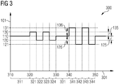
- FIG. 3 shows a schematic excitation frequency curve 300 through which a power control of a resonator, without changing an amplitude of the excitation of the resonator.
- a time 301 is plotted on a horizontal axis of the graph of the FIG. 3 .
- the excitation frequency 101 is applied, with which the resonator is excited.
- FIG. 4 shows in a schematic graph, an amplitude curve 400 of the oscillation amplitude of the resonator, which during the excitation of the resonator according to the excitation frequency curve 300 of the FIG. 3 established.
- the time 301 is also plotted.
- the oscillation amplitude 102 of the resonator oscillation is shown on the vertical axis of the graph.
- the resonator with the resonator frequency 110 is excited.
- the maximum amplitude 140 of the resonator occurs.
- the energy fed into the resonator is to be reduced.
- the time between the second time 320 and the third time 330 is subdivided into a second time period 321, a third time period 322, a fourth time period 323 and a fifth time period 324.
- the periods 321, 322, 323, 324 preferably each last about the same length.
- the second period 321 and the fourth period 323, the resonator with the increased frequency 130 is excited.
- the reduced frequency resonator 120 is excited. Consequently, a resonator oscillation occurs between the second time 320 and the third time 330 in the resonator with the reduced amplitude 150.
- the power fed into the resonator is thus less than between the first time 310 and the second time 320. Since the resonator between the second time 320 and the third time 330 always alternately with the increased frequency 130 and the reduced frequency 120 is excited, the resulting phase position changes 225, 235 average out between the excitation and the resonator oscillation. Thus, the phase shift 201 between the excitation and the resonator oscillation remains at the resonant phase position 210 in the time average.
- the resonator is excited between the second time 320 and the third time 330 only during two periods 321, 323 at the increased frequency 130 and during two periods 322, 324 at the reduced frequency 120.
- the time interval between the second time 320 and the third time 330 is preferably subdivided into substantially more individual time periods with different excitation frequency 101.
- the reduced frequency 120 and the increased frequency 130 thus alternate much more frequently.
- the resonator is excited again at the resonance frequency 110.
- the resonator oscillation again assumes the maximum amplitude 140 between the third time 330 and the fourth time 340.
- the power fed into the resonator is thus maximum again.
- the power fed into the resonator is to be reduced even further than between the second time 320 and the third time 330. This is achieved by switching the resonator between the fourth time 340 and the fifth time 350 alternately with a second reduced frequency 121 and a second increased frequency 131 is excited.
- the second reduced frequency 121 differs from the resonance frequency 110 by a third frequency difference 126.
- the second increased frequency 131 differs from the resonant frequency 110 of the resonator by a fourth frequency difference 136.
- the third frequency difference 126 and the fourth frequency difference 136 have different signs and approximately matching amounts. However, the magnitude of the third frequency difference 126 is greater than the magnitude of the first frequency difference 125. The magnitude of the fourth frequency difference 136 is greater than the magnitude of the second frequency difference 135. Off FIG. 1 It can be seen that, as a result of the frequency differences 126, 136 increased in relation to the frequency differences 125, 135, the power fed into the resonator when excited with the second boosted frequency 131 and the second reduced frequency 121 is greater than that of the reduced frequency resonator 120 and increased Frequency 130 is additionally reduced.
- the time interval between the fourth time 340 and the fifth time 350 is divided into a seventh time period 341, an eighth time period 342, a ninth time period 343, and a tenth time period 344.
- the time interval between the fourth time 340 and the fifth time 350 could also be divided into a much larger number of individual time periods.
- the resonator is excited at the second increased frequency 131.
- the eighth period 342 and the tenth period 344 the second reduced frequency resonator 121 is excited.
- an oscillation with a second reduced amplitude 151 occurs between the fourth time 340 and the fifth time 350 in the resonator.
- the second reduced amplitude 151 is lower than the maximum amplitude 140 and also lower than the reduced amplitude 150.
- the power fed into the resonator between the fourth time 340 and the fifth time 350 is lower than during any other time between the first time 310 and the fourth time 340.
- the second reduced frequency 121 and the second increased frequency 131 are thus arranged approximately symmetrically about the resonance frequency 110, which compensate by the excitation of the resonator with the second reduced Frequency 121 and the second increased frequency 131 adjusting phase changes between the excitation and the resonator oscillation in the time average between the fourth time 340 and the fifth time point 350th
- the excitation amplitude with which the resonator is excited must not be varied in this method. Instead, the frequency at which the resonator is excited is varied. If the resonator is excited with its resonance frequency, then the power fed into the resonator is maximum. If the resonator is excited at a frequency different from the resonance frequency, the power fed into the resonator is reduced, although a phase shift between the excitation and the resonator oscillation also changes. However, if the resonator is excited rapidly alternately at two different frequencies, which are approximately symmetrical about the resonance frequency, then the resulting phase shifts average out.
- the variation of the excitation frequency can be done by applying the excitation frequency with jitter.
- FIG. 5 shows a schematic representation of an exemplary resonator 500, which is suitable for carrying out the method described.
- the resonator arrangement 500 may be, for example, a resonator arrangement in a particle accelerator for accelerating electrically charged particles.
- the resonator arrangement 500 comprises a resonator 510.
- the resonator 510 is designed as an RF cavity in the illustrated example.
- the resonator 510 is in the example shown a so-called pillbox resonator with a cylindrical shape.
- a lateral surface of the cylindrical resonator 510 is formed by a metallic resonator wall 520.
- the Resonatorwandung 520 has a circumferential slot 530, in which an electrically insulating material is arranged.
- an excitation device 540 is arranged, which preferably has a solid-state switch.
- a high-frequency electrical current flow can be induced between the two sections of the resonator wall 520 delimited from one another by the slot 530, whereby a resonator oscillation in the resonator 510 is excited.
- the excitation device 540 is designed to excite the resonator 510 according to the method described above.
- the starting device 540 In order to control the power fed into the resonator 510, the starting device 540 thus varies the frequency of the voltage applied across the slot 530 of the resonator wall 520.
- the output amplitude of the starting device 540 remains constant. This has the advantage that the starting device 540 can be formed with a fixed amplifier chain, which does not have to be variable. This advantageously results in a simple construction of the starting device 540. In addition, this makes it possible to form the exciting device 540 advantageously with high efficiency.
Landscapes
- Physics & Mathematics (AREA)
- Engineering & Computer Science (AREA)
- Plasma & Fusion (AREA)
- Spectroscopy & Molecular Physics (AREA)
- Electromagnetism (AREA)
- Inductance-Capacitance Distribution Constants And Capacitance-Resistance Oscillators (AREA)
- Oscillators With Electromechanical Resonators (AREA)
- Particle Accelerators (AREA)
- Control Of Motors That Do Not Use Commutators (AREA)
- Apparatuses For Generation Of Mechanical Vibrations (AREA)
- Piezo-Electric Or Mechanical Vibrators, Or Delay Or Filter Circuits (AREA)
Description
Resonatoranordnung und Verfahren zum Anregen eines Resonators Die vorliegende Erfindung betrifft ein Verfahren zum Anregen eines Resonators gemäß Patentanspruch 1, sowie eine Resonatoranordnung mit einem Resonator und einer Anregevorrichtung gemäß Patentanspruch 7.Resonator arrangement and method for exciting a resonator The present invention relates to a method for exciting a resonator according to patent claim 1, as well as to a resonator arrangement comprising a resonator and a starting device according to patent claim 7.
Resonatoren, also schwingfähige Systeme, existieren in vielen Varianten. Resonatoren können beispielsweise als RF-Kavitäten ausgebildet sein, in denen sich elektromagnetische Schwingungen anregen lassen. Es ist bekannt, solche RF-Kavitäten in Teilchenbeschleunigern zum Beschleunigen elektrisch geladener Teilchen zu verwenden.Resonators, ie oscillatory systems, exist in many variants. Resonators may be formed, for example, as RF cavities in which electromagnetic oscillations can be excited. It is known to use such RF cavities in particle accelerators for accelerating electrically charged particles.
Zum Anregen und Aufrechterhalten einer Resonatorschwingung muss dem Resonator mittels einer Anregevorrichtung von außen Energie zugeführt werden. Bei als RF-Kavitäten ausgebildeten Resonatoren von Teilchenbeschleunigern werden hierzu Hochfrequenzquellen verwendet. Um die Menge der in den Resonator eingespeisten Energie zu regulieren, wird herkömmlicherweise eine Ausgangsamplitude dieser Hochfrequenzquellen reguliert. Insbesondere bei Verwendung von Festkörperschaltern zur Anregung erfordert diese Amplitudenmodulierbarkeit allerdings einen erheblichen Aufwand und reduziert die Effizienz der bekannten Anregevorrichtungen.To excite and maintain a resonator oscillation, energy must be supplied to the resonator from the outside by means of an excitation device. For resonators of particle accelerators designed as RF cavities, high frequency sources are used for this purpose. In order to regulate the amount of energy injected into the resonator, conventionally, an output amplitude of these high frequency sources is regulated. In particular, when using solid-state switches for excitation, however, this amplitude modulability requires considerable effort and reduces the efficiency of the known excitation devices.
Das Dokument
Die Aufgabe der vorliegenden Erfindung besteht darin, ein verbessertes Verfahren zum Anregen eines Resonators anzugeben. Diese Aufgabe wird durch ein Verfahren mit den Merkmalen des Anspruchs 1 gelöst. Eine weitere Aufgabe der vorliegenden Erfindung besteht darin, eine verbesserte Resonatoranordnung mit einem Resonator und einer Anregevorrichtung bereitzustellen. Diese Aufgabe wird durch eine Resonatoranordnung mit den Merkmalen des Anspruches 7 gelöst. Bevorzugten Weiterbildungen sind in den abhängigen Ansprüchen angegeben.The object of the present invention is to provide an improved method for exciting a resonator. This object is achieved by a method having the features of claim 1. A further object of the present invention is to provide an improved resonator arrangement with a resonator and an exciting device. This object is achieved by a resonator arrangement with the features of claim 7. Preferred developments are specified in the dependent claims.
Bei einem erfindungsgemäßen Verfahren zum Anregen eines Resonators, der eine Resonanzfrequenz aufweist, wird der Resonator während eines ersten Zeitraums mit einer ersten Frequenz angeregt, die sich um eine erste Frequenzdifferenz von der Resonanzfrequenz unterscheidet. Während eines zweiten Zeitraums wird der Resonator mit einer zweiten Frequenz angeregt, die sich um eine zweite Frequenzdifferenz von der Resonanzfrequenz unterscheidet. Dabei weisen die erste Frequenzdifferenz und die zweite Frequenzdifferenz unterschiedliche Vorzeichen auf. Außerdem unterscheiden sich die Beträge der ersten Frequenzdifferenz und der zweiten Frequenzdifferenz um weniger als 10% des größeren Betrags voneinander. Mit anderen Worten liegen die erste Frequenz und die zweite Frequenz also möglichst symmetrisch um die Resonanzfrequenz. Vorteilhafterweise wird dem Resonator durch die Anregung mit den von der Resonanzfrequenz verschiedenen ersten und zweiten Frequenzen weniger Energie zugeführt. Durch die etwa symmetrische Lage der ersten Frequenz und der zweiten Frequenz um die Resonanzfrequenz wird eine durch die Anregung des Resonators mit von der Resonanzfrequenz verschiedenen Frequenzen bewirkte Phasenverschiebung der Resonatorschwingung herausgemittelt. Ausserdem, werden die erste Frequenzdifferenz und die zweite Frequenzdifferenz erhöht, wenn eine Schwingungsamplitude des Resonators reduziert werden soll, und/oder werden die erste Frequenzdifferenz und die zweite Frequendifferenz reduziert, wenn eine Schwingungsamplitude des Resonators erhöht werden soll. Vorteilhafterweise erlaubt es das Verfahren dadurch, die in den Resonator eingespeiste Leistung zu regeln, ohne die Amplitude der Anregung zu variieren. Dadurch ist das Verfahren technisch vorteilhafterweise ohne großen Aufwand umzusetzen.In a method according to the invention for exciting a resonator having a resonant frequency, the resonator is excited during a first period of time at a first frequency which differs from the resonant frequency by a first frequency difference. During a second period, the resonator is excited at a second frequency that differs from the resonant frequency by a second frequency difference. In this case, the first frequency difference and the second frequency difference have different signs. In addition, the amounts of the first frequency difference and the second frequency difference differ by less than 10% of the larger amount from each other. In other words, the first frequency and the second frequency are as symmetrical as possible about the resonance frequency. Advantageously, less energy is supplied to the resonator by excitation at the first and second frequencies different from the resonant frequency. Due to the approximately symmetrical position of the first frequency and the second frequency around the resonance frequency, a phase shift of the resonator oscillation caused by the excitation of the resonator at frequencies other than the resonance frequency is averaged out. In addition, the first frequency difference and the second frequency difference are increased when an oscillation amplitude of the resonator is to be reduced, and / or the first frequency difference and the second frequency difference are reduced when an oscillation amplitude of the resonator is to be increased. Advantageously, the method thereby allows to regulate the power fed into the resonator without varying the amplitude of the excitation. As a result, the method is technically advantageously implement without much effort.
In einer bevorzugten Ausführungsform des Verfahrens folgen erste Zeiträume und zweite Zeiträume wiederholt aufeinander. Vorteilhafterweise können die ersten Zeiträume und die zweiten Zeiträume dann jeweils sehr kurz bemessen sein, wodurch sich die durch die Anregung des Resonators mit der ersten Frequenz und der zweiten Frequenz bewirkten Phasenverschiebungen der Resonatorschwingung besonders wirksam herausmitteln.In a preferred embodiment of the method, first time periods and second time periods follow one another repeatedly. Advantageously, the first time periods and the second time periods can then be dimensioned very short in each case, as a result of which the phase shifts of the resonator oscillation caused by the excitation of the resonator with the first frequency and the second frequency are brought out particularly effectively.
Es ist zweckmäßig, dass der erste Zeitraum und der zweite Zeitraum die gleiche Länge aufweisen. Vorteilhafterweise wird auch hierdurch eine besonders wirksame Herausmittelung von Phasenverschiebungen der Resonatorschwingung unterstützt.It is expedient that the first period and the second period have the same length. Advantageously This also supports a particularly effective determination of phase shifts of the resonator oscillation.
In einer bevorzugten Ausführungsform des Verfahrens wird der Resonator während des ersten Zeitraums und des zweiten Zeitraums mit konstanter Anregungsamplitude angeregt. Vorteilhafterweise kann das Verfahren dann ohne Regulierung der Anregungsamplitude umgesetzt werden.In a preferred embodiment of the method, the resonator is excited during the first time period and the second time period with a constant excitation amplitude. Advantageously, the method can then be implemented without regulation of the excitation amplitude.
In einer Weiterbildung des Verfahrens wird der Resonator während eines weiteren Zeitraums mit der Resonanzfrequenz angeregt. Vorteilhafterweise erhöht sich dann die während des weiteren Zeitraums dem Resonator zugeführte Leistung.In a further development of the method, the resonator is excited at a resonant frequency during a further period of time. Advantageously, the power supplied to the resonator during the further period then increases.
Bevorzugt wird der Resonator während des ersten Zeitraums, des zweiten Zeitraums und des weiteren Zeitraums mit konstanter Anregungsamplitude angeregt. Bevorzugt kann zur Anregung des Resonators dann eine Anregevorrichtung verwendet werden, bei der eine Regulierbarkeit der Anregungsamplitude nicht notwendigerweise möglich sein muss.Preferably, the resonator is excited during the first period, the second period and the further period of constant excitation amplitude. Preferably, an excitation device can then be used to excite the resonator, in which an adjustability of the excitation amplitude does not necessarily have to be possible.
Eine erfindungsgemäße Resonatoranordnung umfasst einen Resonator und eine Anregevorrichtung zum Anregen einer Schwingung des Resonators. Dabei ist die Anregevorrichtung ausgebildet, ein Verfahren der vorgenannten Art auszuführen. Vorteilhafterweise ist es dann nicht erforderlich, die Anregevorrichtung mit veränderbarer Ausgangsamplitude auszubilden. Dadurch kann die Anregevorrichtung vorteilhafterweise einfach und eine hohe Effizienz aufweisend ausgebildet sein.A resonator arrangement according to the invention comprises a resonator and an exciting device for exciting a vibration of the resonator. In this case, the starter device is formed, to carry out a method of the aforementioned type. Advantageously, it is then not necessary to form the exciting device with variable output amplitude. As a result, the starting device can advantageously be formed simply and with high efficiency.
In einer Ausführungsform der Resonatoranordnung ist die Schwingung eine elektromagnetische Schwingung. Vorteilhafterweise kann die Resonatoranordnung dann für viele technische Zwecke genutzt werden.In one embodiment of the resonator arrangement, the oscillation is an electromagnetic oscillation. Advantageously, the resonator arrangement can then be used for many technical purposes.
In einer bevorzugten Ausführungsform der Resonatoranordnung ist der Resonator als RF-Kavität ausgebildet. Vorteilhafterweise können RF-Kavitäten für viele technische Zwecke verwendet werden.In a preferred embodiment of the resonator arrangement, the resonator is designed as an RF cavity. Advantageously, RF cavities can be used for many technical purposes.
In einer besonders bevorzugten Ausführungsform der Resonatoranordnung ist der Resonator ein Resonator eines Teilchenbeschleunigers. Vorteilhafterweise kann der Resonator der Resonatoranordnung dann zur Beschleunigung elektrisch geladener Teilchen verwendet werden. Wegen des enormen Energieverbrauchs von Teilchenbeschleunigern ist eine bei dieser Resonatoranordnung ermöglichte Ausgestaltung der Anregevorrichtung mit hoher Effizienz vorteilhafterweise besonders günstig.In a particularly preferred embodiment of the resonator arrangement, the resonator is a resonator of a particle accelerator. Advantageously, the resonator of the resonator arrangement can then be used to accelerate electrically charged particles. Because of the enormous energy consumption of particle accelerators, an embodiment of the exciting device with high efficiency which is made possible with this resonator arrangement is advantageously particularly favorable.
In einer Ausführungsform der Resonatoranordnung weist die Anregevorrichtung einen Festkörperschalter auf. Vorteilhafterweise ermöglicht die Verwendung von Festkörperschaltungen eine kompakte, kostengünstige und energieeffiziente Ausgestaltung der Anregevorrichtung.In one embodiment of the resonator arrangement, the starting device has a solid-state switch. Advantageously, the use of solid-state circuits allows a compact, cost-effective and energy-efficient design of the exciting device.
Die oben beschriebenen Eigenschaften, Merkmale und Vorteile dieser Erfindung, sowie die Art und Weise, wie diese erreicht werden, werden klarer und deutlicher verständlich im Zusammenhang mit der folgenden Beschreibung der Ausführungsbeispiele, die im Zusammenhang mit den Zeichnungen näher erläutert werden. Hierbei zeigen:
-
Figur 1 einen exemplarischen Amplituden-Frequenz-Gang eines Resonators; -
Figur 2 ein exemplarisches Diagramm einer Phasenlage zwischen einer Resonatorschwingung und einer externen Anregung; -
Figur 3 einen Anregefrequenzverlauf einer Anregung eines Resonators; -
Figur 4 einen Amplitudenverlauf einer Resonatorschwingung; und -
Figur 5 eine schematische Resonatoranordnung.
-
FIG. 1 an exemplary amplitude-frequency response of a resonator; -
FIG. 2 an exemplary diagram of a phase relationship between a resonator and an external excitation; -
FIG. 3 an exciting frequency characteristic of an excitation of a resonator; -
FIG. 4 an amplitude characteristic of a resonator oscillation; and -
FIG. 5 a schematic resonator arrangement.
Auf einer horizontalen Achse des Graphen der
Der Amplituden-Frequenz-Gang 100 weist bei einer Resonanzfrequenz 110 des Resonators eine maximale Amplitude 140 auf. Bei Anregungsfrequenzen 101, die größer oder kleiner als die Resonanzfrequenz 110 des Resonators sind, fällt die im Resonator angeregte Amplitude ab. So weist die angeregte Resonatorschwingung bei einer reduzierten Frequenz 120, die kleiner als die Resonanzfrequenz 110 ist, nur eine reduzierte Amplitude 150 auf. Bei einer erhöhten Frequenz 130, die größer als die Resonanzfrequenz 110 ist, weist die Resonatorschwingung ebenfalls die reduzierte Amplitude 150 auf. Der Abfall des Amplituden-Frequenz-Gangs 100 außerhalb der Resonanzfrequenz 110 ist umso steiler, je höher die Güte des Resonators ist. Die Amplituden bei der reduzierten Frequenz 120 und bei der erhöhten Frequenz 130 könnten sich auch voneinander unterscheiden.The amplitude-
Die reduzierte Frequenz 120 unterscheidet sich von der Resonanzfrequenz 110 um eine erste Frequenzdifferenz 125. Die erhöhte Frequenz 130 unterscheidet sich von der Resonanzfrequenz 110 um eine zweite Frequenzdifferenz 135. Die erste Frequenzdifferenz 125 und die zweite Frequenzdifferenz 135 weisen unterschiedliche Vorzeichen auf. Bevorzugt weisen die erste Frequenzdifferenz 125 und die zweite Frequenzdifferenz 135 jedoch etwa gleiche Beträge auf. Dann liegt die Resonanzfrequenz 110 mittig zwischen der reduzierten Frequenz 120 und der erhöhten Frequenz 130.The reduced
Wird der Resonator mit der Resonanzfrequenz 110 angeregt, so stellt sich eine Resonatorschwingung mit der maximalen Amplitude 140 ein. Die dem Resonator zugeführte Energie ist in diesem Fall maximal. Wird der Resonator mit der reduzierten Frequenz 120 oder mit der erhöhten Frequenz 130 angeregt, so stellt sich eine Resonatorschwingung mit der reduzierten Amplitude 150 ein. In diesem Fall wird durch die äußere Anregung also weniger Energie in den Resonator eingespeist. Somit kann durch eine Variation der Anregungsfrequenz 101, mit der der Resonator angeregt wird, die in den Resonator eingespeiste Energie variiert werden.If the resonator is excited with the
Bei einer Anregung des Resonators mit der Resonanzfrequenz 110 stellt sich eine resonante Phasenlage 210 zwischen der äußeren Anregung und der Resonatorschwingung ein. Die resonante Phasenlage 210 kann beispielsweise eine Phasenverschiebung von 90° zwischen der Anregung und der Resonatorschwingung sein. Außerhalb der Resonanzfrequenz 110 ändert sich die Phasenverschiebung 201 zwischen Anregung und Resonatorschwingung. So stellt sich bei einer Anregung des Resonators mit der reduzierten Frequenz 120 eine erste Phasenlage 220 und bei einer Anregung des Resonators mit der erhöhten Frequenz 130 eine zweite Phasenlage 230 ein. Dies ist in der Regel unerwünscht. Gewünscht ist, dass die Phasenverschiebung 201 zwischen der äußeren Anregung und der Resonatorschwingung bei der resonanten Phasenlage 210 verbleibt.Upon excitation of the resonator with the
Im in
Die reduzierte Frequenz 120 und die erhöhte Frequenz 130 sind also so gewählt, dass die sich bei Anregung mit der reduzierten Frequenz 120 einstellende erste Phasenlage 220 und die sich bei Anregung mit der erhöhten Frequenz 130 einstellende Phasenlage 230 möglichst symmetrisch um die resonante Phasenlage 210 angeordnet sind, die erste Phasenlage-Änderung 225 und die zweite Phasenlage-Änderung 235 also möglichst identische Beträge aufweisen. Weniger wichtig ist, ob sich bei Anregung mit der reduzierten Frequenz 120 und bei Anregung mit der erhöhten Frequenz 130 die gleiche reduzierte Amplitude 150 einstellt. Es ist unkritisch, wenn sich bei der reduzierten Frequenz 120 eine andere Schwingungsamplitude 102 einstellt, als bei der erhöhten Frequenz 130.The reduced
Bei Verwendung eines Resonators mit hoher Güte ist die genannte Forderung erfüllt, wenn die reduzierte Frequenz 120 und die erhöhte Frequenz 130 etwa symmetrisch um die Resonanzfrequenz 110 angeordnet sind, die erste Frequenzdifferenz 125 und die zweite Frequenzdifferenz 135 also etwa gleiche Beträge aufweisen. Bevorzugt unterscheiden sich die Beträge der ersten Frequenzdifferenz 125 und der zweiten Frequenzdifferenz 135 um weniger als 10% des größeren Betrags. Besonders bevorzugt unterschieden sich die Beträge der ersten Frequenzdifferenz 125 und der zweiten Frequenzdifferenz 135 um einen noch wesentlich geringeren Bruchteil, beispielsweise um lediglich 5% oder 1% des größeren Betrags.When using a resonator with high quality said requirement is met if the reduced
Wird der Resonator abwechselnd mit der reduzierten Frequenz 120 und der erhöhten Frequenz 130 angeregt, so kompensieren sich die sich ergebenden Phasenlage-Änderungen 225, 235 gegenseitig. Diese Kompensation funktioniert umso besser, je schneller die Intervalle der Anregung mit der reduzierten Frequenz 120 und mit der erhöhten Frequenz 130 aufeinander folgen. Dies kann beispielsweise erreicht werden, indem die Anregungsfrequenz kontrolliert mit einem Jitter beaufschlagt wird.If the resonator is alternately excited with the reduced
Während eines ersten Zeitraums 311 zwischen einem ersten Zeitpunkt 310 und einem dem ersten Zeitpunkt 310 zeitlich nachfolgenden zweiten Zeitpunkt 320 wird der Resonator mit der Resonatorfrequenz 110 angeregt. Somit stellt sich zwischen dem ersten Zeitpunkt 310 und dem zweiten Zeitpunkt 320 im Resonator die maximale Amplitude 140 der Resonatorschwingung ein.During a
Zwischen dem zweiten Zeitpunkt 320 und einem dritten Zeitpunkt 330 soll die in den Resonator eingespeiste Energie reduziert werden. Hierzu ist die Zeit zwischen dem zweiten Zeitpunkt 320 und dem dritten Zeitpunkt 330 in einen zweiten Zeitraum 321, einen dritten Zeitraum 322, einen vierten Zeitraum 323 und einen fünften Zeitraum 324 unterteilt. Die Zeiträume 321, 322, 323, 324 dauern bevorzugt jeweils etwa gleich lang. Während des zweiten Zeitraums 321 und des vierten Zeitraums 323 wird der Resonator mit der erhöhten Frequenz 130 angeregt. Während des dritten Zeitraums 322 und des fünften Zeitraums 324 wird der Resonator mit der reduzierten Frequenz 120 angeregt. Folglich stellt sich zwischen dem zweiten Zeitpunkt 320 und dem dritten Zeitpunkt 330 im Resonator eine Resonatorschwingung mit der reduzierten Amplitude 150 ein. Zwischen dem zweiten Zeitpunkt 320 und dem dritten Zeitpunkt 330 ist die in den Resonator eingespeiste Leistung also geringer als zwischen dem ersten Zeitpunkt 310 und dem zweiten Zeitpunkt 320. Da der Resonator zwischen dem zweiten Zeitpunkt 320 und dem dritten Zeitpunkt 330 immer abwechselnd mit der erhöhten Frequenz 130 und der reduzierten Frequenz 120 angeregt wird, mitteln sich die sich dabei ergebenden Phasenlage-Änderungen 225, 235 zwischen der Anregung und der Resonatorschwingung heraus. Somit verbleibt die Phasenverschiebung 201 zwischen der Anregung und der Resonatorschwingung im zeitlichen Mittel bei der resonanten Phasenlage 210.Between the
In den schematischen Darstellungen der
Während eines sechsten Zeitraums 331 zwischen dem dritten Zeitpunkt 330 und einem vierten Zeitpunkt 340 wird der Resonator wieder mit der Resonanzfrequenz 110 angeregt. Dadurch nimmt die Resonatorschwingung zwischen dem dritten Zeitpunkt 330 und dem vierten Zeitpunkt 340 wieder die maximale Amplitude 140 an. Zwischen dem dritten Zeitpunkt 330 und dem vierten Zeitpunkt 340 ist die in dem Resonator eingespeiste Leistung somit wieder maximal.During a
Zwischen dem vierten Zeitpunkt 340 und einem fünften Zeitpunkt 350 soll die in den Resonator eingespeiste Leistung noch weiter reduziert werden als zwischen dem zweiten Zeitpunkt 320 und dem dritten Zeitpunkt 330. Dies wird erreicht, indem der Resonator zwischen dem vierten Zeitpunkt 340 und dem fünften Zeitpunkt 350 wechselweise mit einer zweiten reduzierten Frequenz 121 und einer zweiten erhöhten Frequenz 131 angeregt wird. Die zweite reduzierte Frequenz 121 unterscheidet sich dabei von der Resonanzfrequenz 110 um eine dritte Frequenzdifferenz 126. Die zweite erhöhte Frequenz 131 unterscheidet sich von der Resonanzfrequenz 110 des Resonators um eine vierte Frequenzdifferenz 136.Between the
Die dritte Frequenzdifferenz 126 und die vierte Frequenzdifferenz 136 weisen unterschiedliche Vorzeichen und etwa übereinstimmende Beträge auf. Der Betrag der dritten Frequenzdifferenz 126 ist jedoch größer als der Betrag der ersten Frequenzdifferenz 125. Der Betrag der vierten Frequenzdifferenz 136 ist größer als der Betrag der zweiten Frequenzdifferenz 135. Aus
In der schematischen Darstellung der
Dadurch, dass die dritte Frequenzdifferenz 126 und die vierte Frequenzdifferenz 136 etwa gleiche Beträge aufweisen, die zweite reduzierte Frequenz 121 und die zweite erhöhte Frequenz 131 also etwa symmetrisch um die Resonanzfrequenz 110 angeordnet sind, kompensieren sich die durch die Anregung des Resonators mit der zweiten reduzierten Frequenz 121 und der zweiten erhöhten Frequenz 131 einstellenden Phasenlage-Änderungen zwischen der Anregung und der Resonatorschwingung im zeitlichen Mittel zwischen dem vierten Zeitpunkt 340 und dem fünften Zeitpunkt 350.Characterized in that the
Das anhand der
Die Resonatoranordnung 500 umfasst einen Resonator 510. Der Resonator 510 ist im dargestellten Beispiel als RF-Kavität ausgebildet. Der Resonator 510 ist im dargestellten Beispiel ein sogenannter Pillbox-Resonator mit einer zylindrischen Form. Eine Mantelfläche des zylindrischen Resonators 510 wird durch eine metallische Resonatorwandung 520 gebildet.The
Im Resonator 510 kann eine elektromagnetische Schwingung angeregt werden. Hierzu weist die Resonatorwandung 520 einen umlaufenden Schlitz 530 auf, in dem ein elektrisch isolierendes Material angeordnet ist. Über den Schlitz 530 ist eine Anregevorrichtung 540 angeordnet, die bevorzugt einen Festkörperschalter aufweist. Mittels der Anregevorrichtung 540 kann zwischen den beiden durch den Schlitz 530 voneinander abgegrenzten Abschnitten der Resonatorwandung 520 ein hochfrequenter elektrischer Stromfluss induziert werden, wodurch eine Resonatorschwingung im Resonator 510 angeregt wird.In the
Die Anregevorrichtung 540 ist ausgebildet, den Resonator 510 gemäß des vorab beschriebenen Verfahrens anzuregen. Die Anregevorrichtung 540 variiert zur Steuerung der in den Resonator 510 eingespeisten Leistung also die Frequenz der über den Schlitz 530 der Resonatorwandung 520 angelegten Spannung. Die Ausgangsamplitude der Anregevorrichtung 540 bleibt dabei konstant. Dies hat den Vorteil, dass die Anregevorrichtung 540 mit einer festen Verstärkerkette ausgebildet sein kann, die nicht veränderlich sein muss. Hierdurch ergibt sich vorteilhafterweise ein einfacher Aufbau der Anregevorrichtung 540. Außerdem ermöglicht dies, die Anregevorrichtung 540 vorteilhafterweise mit hohem Wirkungsgrad auszubilden.The
Obwohl die Erfindung im Detail durch das bevorzugte Ausführungsbeispiel näher illustriert und beschrieben wurde, ist die Erfindung nicht durch die offenbarten Beispiele eingeschränkt. Andere Variationen können vom Fachmann hieraus abgeleitet werden, ohne den Schutzumfang der Erfindung zu verlassen. Although the invention has been illustrated and described in detail by the preferred embodiment, the invention is not limited by the disclosed examples. Other variations can be deduced therefrom by those skilled in the art without departing from the scope of the invention.
Claims (11)
- Method for exciting a resonator (510),
wherein the resonator (510) has a resonant frequency (110),
wherein the resonator (510) is excited during a first time period (321, 323, 341, 343) with a first frequency (130, 131) which differs from the resonant frequency (110) by a first frequency difference (135, 136),
wherein the resonator (510) is excited during a second time period (322, 324, 342, 344) with a second frequency (120, 121) which differs from the resonant frequency (110) by a second frequency difference (125, 126), wherein the first frequency difference (135, 136) and the second frequency difference (125, 126) have different signs,
wherein the magnitudes of the first frequency difference (135, 136) and of the second frequency difference (125, 126) differ by less than 10% of the larger magnitude, characterized in that
the first frequency difference (135, 136) and the second frequency difference (125, 126) are increased if an oscillation amplitude (102) of the resonator (510) is to be reduced, and/or
the first frequency difference (135, 136) and the second frequency difference (125, 126) are reduced if an oscillation amplitude (102) of the resonator (510) is to be increased. - Method according to Claim 1,
wherein first time periods (321, 323, 341, 343) and second time periods (322, 324, 342, 344) repeatedly follow one another. - Method according to one of the preceding claims,
wherein the first time period (321, 323, 341, 343) and the second time period (322, 324, 342, 344) have the same length. - Method according to one of the preceding claims,
wherein the resonator (510) is excited with a constant excitation amplitude during the first time period (321, 323, 341, 343) and the second time period (322, 324, 342, 344). - Method according to one of the preceding claims,
wherein the resonator (510) is excited with the resonant frequency (110) during a further time period (311, 331). - Method according to Claim 5,
wherein the resonator (510) is excited with a constant excitation amplitude during the first time period (321, 323, 341, 343), the second time period (322, 324, 342, 344) and the further time period (311, 331). - Resonator arrangement (500)
comprising a resonator (510) and an excitation device (540) for exciting an oscillation of the resonator (510), wherein the excitation device (540) is embodied to carry out a method according to one of the preceding claims. - Resonator arrangement (500) according to Claim 7,
wherein the oscillation is an electromagnetic oscillation. - Resonator arrangement (500) according to Claim 8,
wherein the resonator (510) is embodied as an RF cavity. - Resonator arrangement (500) according to one of Claims 7 to 9,
wherein the resonator (510) is a resonator of a particle accelerator. - Resonator arrangement (500) according to one of Claims 7 to 10,
wherein the excitation device (540) comprises a solid-state switch.
Applications Claiming Priority (1)
| Application Number | Priority Date | Filing Date | Title |
|---|---|---|---|
| PCT/EP2012/054995 WO2013139389A1 (en) | 2012-03-21 | 2012-03-21 | Resonator arrangement and method for exciting a resonator |
Publications (2)
| Publication Number | Publication Date |
|---|---|
| EP2805376A1 EP2805376A1 (en) | 2014-11-26 |
| EP2805376B1 true EP2805376B1 (en) | 2016-12-14 |
Family
ID=45976286
Family Applications (1)
| Application Number | Title | Priority Date | Filing Date |
|---|---|---|---|
| EP12714981.3A Not-in-force EP2805376B1 (en) | 2012-03-21 | 2012-03-21 | Resonator arrangement and method for exciting a resonator |
Country Status (9)
| Country | Link |
|---|---|
| US (1) | US9246495B2 (en) |
| EP (1) | EP2805376B1 (en) |
| JP (1) | JP5989222B2 (en) |
| KR (1) | KR101916349B1 (en) |
| CN (1) | CN104247145B (en) |
| IN (1) | IN2014DN07319A (en) |
| PL (1) | PL2805376T3 (en) |
| RU (1) | RU2586410C2 (en) |
| WO (1) | WO2013139389A1 (en) |
Families Citing this family (4)
| Publication number | Priority date | Publication date | Assignee | Title |
|---|---|---|---|---|
| KR20180039069A (en) | 2015-08-11 | 2018-04-17 | 콘티넨탈 테베스 아게 운트 코. 오하게 | Devices for measuring measurement variables |
| DE102015215331A1 (en) * | 2015-08-11 | 2017-02-16 | Continental Teves Ag & Co. Ohg | Electronic control unit |
| DE102016202402A1 (en) | 2016-02-17 | 2017-08-17 | Continental Teves Ag & Co. Ohg | sensor |
| DE102016202403A1 (en) | 2016-02-17 | 2017-08-17 | Continental Teves Ag & Co. Ohg | sensor |
Citations (1)
| Publication number | Priority date | Publication date | Assignee | Title |
|---|---|---|---|---|
| US2790905A (en) * | 1953-06-09 | 1957-04-30 | Marconi Wireless Telegraph Co | Automatic frequency control |
Family Cites Families (14)
| Publication number | Priority date | Publication date | Assignee | Title |
|---|---|---|---|---|
| US2887580A (en) | 1957-04-26 | 1959-05-19 | Gen Electric | Variable output control for linear accelerators |
| SU536628A1 (en) * | 1975-06-13 | 1976-11-25 | Объединенный Институт Ядерных Исследований | Excitation device for linear ion accelerator resonator |
| FR2451061A1 (en) * | 1979-03-09 | 1980-10-03 | Ebauches Sa | PASSIVE MASER |
| US4314209A (en) * | 1980-04-21 | 1982-02-02 | Hughes Aircraft Company | Q-Enhanced resonance-stabilized maser |
| SU876045A1 (en) * | 1980-06-13 | 1987-09-30 | Предприятие П/Я М-5631 | Excitation system of accelerator cavity |
| SU1042598A1 (en) * | 1981-07-30 | 1986-08-23 | Предприятие П/Я А-7094 | Resonant accelerating system |
| SU1143309A2 (en) * | 1983-02-04 | 1986-01-07 | Московский Ордена Трудового Красного Знамени Инженерно-Физический Институт | Accelerating system |
| JP2673365B2 (en) * | 1989-02-23 | 1997-11-05 | アンリツ株式会社 | Resonant frequency control device for cavity resonator |
| JP2995131B2 (en) * | 1993-05-28 | 1999-12-27 | アンリツ株式会社 | Highly stable resonance frequency control device for cavity resonator |
| FR2895170B1 (en) * | 2005-12-15 | 2008-03-07 | Renault Sas | OPTIMIZING THE EXCITATION FREQUENCY OF A RESONATOR |
| US20080068112A1 (en) * | 2006-09-14 | 2008-03-20 | Yu David U L | Rod-loaded radiofrequency cavities and couplers |
| JP5044663B2 (en) * | 2007-09-14 | 2012-10-10 | シュルンベルジェ ホールディングス リミテッド | Particle accelerator |
| US8183801B2 (en) * | 2008-08-12 | 2012-05-22 | Varian Medical Systems, Inc. | Interlaced multi-energy radiation sources |
| US8311187B2 (en) | 2010-01-29 | 2012-11-13 | Accuray, Inc. | Magnetron powered linear accelerator for interleaved multi-energy operation |
-
2012
- 2012-03-21 KR KR1020147029493A patent/KR101916349B1/en active IP Right Grant
- 2012-03-21 EP EP12714981.3A patent/EP2805376B1/en not_active Not-in-force
- 2012-03-21 RU RU2014142269/28A patent/RU2586410C2/en not_active IP Right Cessation
- 2012-03-21 IN IN7319DEN2014 patent/IN2014DN07319A/en unknown
- 2012-03-21 CN CN201280071644.9A patent/CN104247145B/en not_active Expired - Fee Related
- 2012-03-21 PL PL12714981T patent/PL2805376T3/en unknown
- 2012-03-21 JP JP2015500779A patent/JP5989222B2/en not_active Expired - Fee Related
- 2012-03-21 WO PCT/EP2012/054995 patent/WO2013139389A1/en active Application Filing
- 2012-03-21 US US14/386,047 patent/US9246495B2/en not_active Expired - Fee Related
Patent Citations (1)
| Publication number | Priority date | Publication date | Assignee | Title |
|---|---|---|---|---|
| US2790905A (en) * | 1953-06-09 | 1957-04-30 | Marconi Wireless Telegraph Co | Automatic frequency control |
Also Published As
| Publication number | Publication date |
|---|---|
| KR101916349B1 (en) | 2018-11-07 |
| RU2014142269A (en) | 2016-05-20 |
| US9246495B2 (en) | 2016-01-26 |
| US20150048893A1 (en) | 2015-02-19 |
| IN2014DN07319A (en) | 2015-04-24 |
| KR20140139028A (en) | 2014-12-04 |
| RU2586410C2 (en) | 2016-06-10 |
| JP5989222B2 (en) | 2016-09-07 |
| CN104247145B (en) | 2016-10-26 |
| WO2013139389A1 (en) | 2013-09-26 |
| EP2805376A1 (en) | 2014-11-26 |
| CN104247145A (en) | 2014-12-24 |
| PL2805376T3 (en) | 2017-06-30 |
| JP2015516724A (en) | 2015-06-11 |
Similar Documents
| Publication | Publication Date | Title |
|---|---|---|
| EP1797490B1 (en) | Method and device for determining a pwm signal on which a dither frequency is superimposed in order to control a solenoid valve | |
| EP2805376B1 (en) | Resonator arrangement and method for exciting a resonator | |
| DE102014219016B4 (en) | Method for controlling a standing wave accelerator | |
| DE102014103414B3 (en) | Method for controlling a corona ignition system of a cyclically operating internal combustion engine | |
| DE748787C (en) | Runtime coil switched as a quadrupole | |
| DE809328C (en) | Reflection type high frequency vibrator | |
| DE102015104780A1 (en) | Wireless power supply device | |
| EP2684249B1 (en) | Rf generator | |
| DE102015118437A1 (en) | Layer arrangement for a volume wave component | |
| DE102016101660A1 (en) | Method for exciting piezoelectric transducers and sound generating arrangement | |
| DE69110494T2 (en) | Tunable microwave filter. | |
| DE19850447B4 (en) | Non-linear dispersion pulse generator | |
| DE19821382A1 (en) | Method for adjusting the resonance frequency of a ring resonator | |
| DE3401087A1 (en) | ELECTRONIC DISCHARGE OSCILLATOR WITH CROSSED FIELDS | |
| WO2016184965A1 (en) | Bandpass filter comprising a cavity resonator and method for operating, adjusting or producing a bandpass filter of this type | |
| DE2214252C3 (en) | Band filters for electrical oscillations | |
| EP2991158B1 (en) | Generic channel filter | |
| DE1181342B (en) | Linear ion accelerator | |
| EP3095192B1 (en) | Method for controlling switching edges for switched output stages, control device, and output stage | |
| DE102021117830A1 (en) | waveguide device | |
| DE102004023750B4 (en) | Method for operating a gas laser with a pulsed high-frequency voltage and operated according to this method gas laser | |
| DE102010044113A1 (en) | RF cavity and particle accelerator with RF cavity | |
| WO2018095921A1 (en) | Driver circuit, in particular for a pockels cell, and a method for driving a driver circuit | |
| DE1276238B (en) | Mechanical filter | |
| EP4050627A1 (en) | Device for correcting the power factor of an electronic ballast at an ac terminal |
Legal Events
| Date | Code | Title | Description |
|---|---|---|---|
| PUAI | Public reference made under article 153(3) epc to a published international application that has entered the european phase |
Free format text: ORIGINAL CODE: 0009012 |
|
| 17P | Request for examination filed |
Effective date: 20140820 |
|
| AK | Designated contracting states |
Kind code of ref document: A1 Designated state(s): AL AT BE BG CH CY CZ DE DK EE ES FI FR GB GR HR HU IE IS IT LI LT LU LV MC MK MT NL NO PL PT RO RS SE SI SK SM TR |
|
| DAX | Request for extension of the european patent (deleted) | ||
| 17Q | First examination report despatched |
Effective date: 20151116 |
|
| GRAP | Despatch of communication of intention to grant a patent |
Free format text: ORIGINAL CODE: EPIDOSNIGR1 |
|
| RIC1 | Information provided on ipc code assigned before grant |
Ipc: H05H 7/02 20060101ALI20160607BHEP Ipc: H01P 7/06 20060101AFI20160607BHEP Ipc: H05H 7/18 20060101ALI20160607BHEP |
|
| INTG | Intention to grant announced |
Effective date: 20160705 |
|
| GRAS | Grant fee paid |
Free format text: ORIGINAL CODE: EPIDOSNIGR3 |
|
| GRAA | (expected) grant |
Free format text: ORIGINAL CODE: 0009210 |
|
| AK | Designated contracting states |
Kind code of ref document: B1 Designated state(s): AL AT BE BG CH CY CZ DE DK EE ES FI FR GB GR HR HU IE IS IT LI LT LU LV MC MK MT NL NO PL PT RO RS SE SI SK SM TR |
|
| REG | Reference to a national code |
Ref country code: GB Ref legal event code: FG4D Free format text: NOT ENGLISH |
|
| REG | Reference to a national code |
Ref country code: CH Ref legal event code: EP |
|
| REG | Reference to a national code |
Ref country code: IE Ref legal event code: FG4D Free format text: LANGUAGE OF EP DOCUMENT: GERMAN |
|
| REG | Reference to a national code |
Ref country code: AT Ref legal event code: REF Ref document number: 854333 Country of ref document: AT Kind code of ref document: T Effective date: 20170115 |
|
| REG | Reference to a national code |
Ref country code: DE Ref legal event code: R096 Ref document number: 502012009022 Country of ref document: DE |
|
| PG25 | Lapsed in a contracting state [announced via postgrant information from national office to epo] |
Ref country code: LV Free format text: LAPSE BECAUSE OF FAILURE TO SUBMIT A TRANSLATION OF THE DESCRIPTION OR TO PAY THE FEE WITHIN THE PRESCRIBED TIME-LIMIT Effective date: 20161214 |
|
| REG | Reference to a national code |
Ref country code: FR Ref legal event code: PLFP Year of fee payment: 6 |
|
| REG | Reference to a national code |
Ref country code: LT Ref legal event code: MG4D |
|
| REG | Reference to a national code |
Ref country code: NL Ref legal event code: MP Effective date: 20161214 |
|
| PG25 | Lapsed in a contracting state [announced via postgrant information from national office to epo] |
Ref country code: LT Free format text: LAPSE BECAUSE OF FAILURE TO SUBMIT A TRANSLATION OF THE DESCRIPTION OR TO PAY THE FEE WITHIN THE PRESCRIBED TIME-LIMIT Effective date: 20161214 Ref country code: GR Free format text: LAPSE BECAUSE OF FAILURE TO SUBMIT A TRANSLATION OF THE DESCRIPTION OR TO PAY THE FEE WITHIN THE PRESCRIBED TIME-LIMIT Effective date: 20170315 Ref country code: NO Free format text: LAPSE BECAUSE OF FAILURE TO SUBMIT A TRANSLATION OF THE DESCRIPTION OR TO PAY THE FEE WITHIN THE PRESCRIBED TIME-LIMIT Effective date: 20170314 Ref country code: SE Free format text: LAPSE BECAUSE OF FAILURE TO SUBMIT A TRANSLATION OF THE DESCRIPTION OR TO PAY THE FEE WITHIN THE PRESCRIBED TIME-LIMIT Effective date: 20161214 |
|
| PG25 | Lapsed in a contracting state [announced via postgrant information from national office to epo] |
Ref country code: HR Free format text: LAPSE BECAUSE OF FAILURE TO SUBMIT A TRANSLATION OF THE DESCRIPTION OR TO PAY THE FEE WITHIN THE PRESCRIBED TIME-LIMIT Effective date: 20161214 Ref country code: FI Free format text: LAPSE BECAUSE OF FAILURE TO SUBMIT A TRANSLATION OF THE DESCRIPTION OR TO PAY THE FEE WITHIN THE PRESCRIBED TIME-LIMIT Effective date: 20161214 Ref country code: RS Free format text: LAPSE BECAUSE OF FAILURE TO SUBMIT A TRANSLATION OF THE DESCRIPTION OR TO PAY THE FEE WITHIN THE PRESCRIBED TIME-LIMIT Effective date: 20161214 |
|
| PG25 | Lapsed in a contracting state [announced via postgrant information from national office to epo] |
Ref country code: NL Free format text: LAPSE BECAUSE OF FAILURE TO SUBMIT A TRANSLATION OF THE DESCRIPTION OR TO PAY THE FEE WITHIN THE PRESCRIBED TIME-LIMIT Effective date: 20161214 |
|
| PG25 | Lapsed in a contracting state [announced via postgrant information from national office to epo] |
Ref country code: RO Free format text: LAPSE BECAUSE OF FAILURE TO SUBMIT A TRANSLATION OF THE DESCRIPTION OR TO PAY THE FEE WITHIN THE PRESCRIBED TIME-LIMIT Effective date: 20161214 Ref country code: IS Free format text: LAPSE BECAUSE OF FAILURE TO SUBMIT A TRANSLATION OF THE DESCRIPTION OR TO PAY THE FEE WITHIN THE PRESCRIBED TIME-LIMIT Effective date: 20170414 Ref country code: EE Free format text: LAPSE BECAUSE OF FAILURE TO SUBMIT A TRANSLATION OF THE DESCRIPTION OR TO PAY THE FEE WITHIN THE PRESCRIBED TIME-LIMIT Effective date: 20161214 Ref country code: CZ Free format text: LAPSE BECAUSE OF FAILURE TO SUBMIT A TRANSLATION OF THE DESCRIPTION OR TO PAY THE FEE WITHIN THE PRESCRIBED TIME-LIMIT Effective date: 20161214 Ref country code: SK Free format text: LAPSE BECAUSE OF FAILURE TO SUBMIT A TRANSLATION OF THE DESCRIPTION OR TO PAY THE FEE WITHIN THE PRESCRIBED TIME-LIMIT Effective date: 20161214 |
|
| RAP2 | Party data changed (patent owner data changed or rights of a patent transferred) |
Owner name: SIEMENS AKTIENGESELLSCHAFT |
|
| PG25 | Lapsed in a contracting state [announced via postgrant information from national office to epo] |
Ref country code: IT Free format text: LAPSE BECAUSE OF FAILURE TO SUBMIT A TRANSLATION OF THE DESCRIPTION OR TO PAY THE FEE WITHIN THE PRESCRIBED TIME-LIMIT Effective date: 20161214 Ref country code: SM Free format text: LAPSE BECAUSE OF FAILURE TO SUBMIT A TRANSLATION OF THE DESCRIPTION OR TO PAY THE FEE WITHIN THE PRESCRIBED TIME-LIMIT Effective date: 20161214 Ref country code: PT Free format text: LAPSE BECAUSE OF FAILURE TO SUBMIT A TRANSLATION OF THE DESCRIPTION OR TO PAY THE FEE WITHIN THE PRESCRIBED TIME-LIMIT Effective date: 20170414 Ref country code: ES Free format text: LAPSE BECAUSE OF FAILURE TO SUBMIT A TRANSLATION OF THE DESCRIPTION OR TO PAY THE FEE WITHIN THE PRESCRIBED TIME-LIMIT Effective date: 20161214 Ref country code: BG Free format text: LAPSE BECAUSE OF FAILURE TO SUBMIT A TRANSLATION OF THE DESCRIPTION OR TO PAY THE FEE WITHIN THE PRESCRIBED TIME-LIMIT Effective date: 20170314 |
|
| REG | Reference to a national code |
Ref country code: DE Ref legal event code: R097 Ref document number: 502012009022 Country of ref document: DE |
|
| REG | Reference to a national code |
Ref country code: CH Ref legal event code: NV Representative=s name: SIEMENS SCHWEIZ AG, CH Ref country code: CH Ref legal event code: PCOW Free format text: NEW ADDRESS: WERNER-VON-SIEMENS-STRASSE 1, 80333 MUENCHEN (DE) |
|
| PLBE | No opposition filed within time limit |
Free format text: ORIGINAL CODE: 0009261 |
|
| STAA | Information on the status of an ep patent application or granted ep patent |
Free format text: STATUS: NO OPPOSITION FILED WITHIN TIME LIMIT |
|
| REG | Reference to a national code |
Ref country code: CH Ref legal event code: PL |
|
| 26N | No opposition filed |
Effective date: 20170915 |
|
| PG25 | Lapsed in a contracting state [announced via postgrant information from national office to epo] |
Ref country code: MC Free format text: LAPSE BECAUSE OF FAILURE TO SUBMIT A TRANSLATION OF THE DESCRIPTION OR TO PAY THE FEE WITHIN THE PRESCRIBED TIME-LIMIT Effective date: 20161214 Ref country code: DK Free format text: LAPSE BECAUSE OF FAILURE TO SUBMIT A TRANSLATION OF THE DESCRIPTION OR TO PAY THE FEE WITHIN THE PRESCRIBED TIME-LIMIT Effective date: 20161214 |
|
| REG | Reference to a national code |
Ref country code: IE Ref legal event code: MM4A |
|
| PG25 | Lapsed in a contracting state [announced via postgrant information from national office to epo] |
Ref country code: LU Free format text: LAPSE BECAUSE OF NON-PAYMENT OF DUE FEES Effective date: 20170321 |
|
| PG25 | Lapsed in a contracting state [announced via postgrant information from national office to epo] |
Ref country code: SI Free format text: LAPSE BECAUSE OF FAILURE TO SUBMIT A TRANSLATION OF THE DESCRIPTION OR TO PAY THE FEE WITHIN THE PRESCRIBED TIME-LIMIT Effective date: 20161214 Ref country code: IE Free format text: LAPSE BECAUSE OF NON-PAYMENT OF DUE FEES Effective date: 20170321 Ref country code: LI Free format text: LAPSE BECAUSE OF NON-PAYMENT OF DUE FEES Effective date: 20170331 Ref country code: CH Free format text: LAPSE BECAUSE OF NON-PAYMENT OF DUE FEES Effective date: 20170331 |
|
| REG | Reference to a national code |
Ref country code: FR Ref legal event code: PLFP Year of fee payment: 7 |
|
| REG | Reference to a national code |
Ref country code: AT Ref legal event code: MM01 Ref document number: 854333 Country of ref document: AT Kind code of ref document: T Effective date: 20170321 |
|
| PGFP | Annual fee paid to national office [announced via postgrant information from national office to epo] |
Ref country code: DE Payment date: 20180518 Year of fee payment: 7 |
|
| PG25 | Lapsed in a contracting state [announced via postgrant information from national office to epo] |
Ref country code: AT Free format text: LAPSE BECAUSE OF NON-PAYMENT OF DUE FEES Effective date: 20170321 |
|
| PG25 | Lapsed in a contracting state [announced via postgrant information from national office to epo] |
Ref country code: MT Free format text: LAPSE BECAUSE OF FAILURE TO SUBMIT A TRANSLATION OF THE DESCRIPTION OR TO PAY THE FEE WITHIN THE PRESCRIBED TIME-LIMIT Effective date: 20161214 |
|
| PGFP | Annual fee paid to national office [announced via postgrant information from national office to epo] |
Ref country code: PL Payment date: 20190312 Year of fee payment: 8 Ref country code: GB Payment date: 20190313 Year of fee payment: 8 Ref country code: FR Payment date: 20190322 Year of fee payment: 8 |
|
| PGFP | Annual fee paid to national office [announced via postgrant information from national office to epo] |
Ref country code: BE Payment date: 20190320 Year of fee payment: 8 |
|
| PG25 | Lapsed in a contracting state [announced via postgrant information from national office to epo] |
Ref country code: HU Free format text: LAPSE BECAUSE OF FAILURE TO SUBMIT A TRANSLATION OF THE DESCRIPTION OR TO PAY THE FEE WITHIN THE PRESCRIBED TIME-LIMIT; INVALID AB INITIO Effective date: 20120321 |
|
| REG | Reference to a national code |
Ref country code: DE Ref legal event code: R119 Ref document number: 502012009022 Country of ref document: DE |
|
| PG25 | Lapsed in a contracting state [announced via postgrant information from national office to epo] |
Ref country code: CY Free format text: LAPSE BECAUSE OF FAILURE TO SUBMIT A TRANSLATION OF THE DESCRIPTION OR TO PAY THE FEE WITHIN THE PRESCRIBED TIME-LIMIT Effective date: 20161214 |
|
| PG25 | Lapsed in a contracting state [announced via postgrant information from national office to epo] |
Ref country code: MK Free format text: LAPSE BECAUSE OF FAILURE TO SUBMIT A TRANSLATION OF THE DESCRIPTION OR TO PAY THE FEE WITHIN THE PRESCRIBED TIME-LIMIT Effective date: 20161214 |
|
| PG25 | Lapsed in a contracting state [announced via postgrant information from national office to epo] |
Ref country code: DE Free format text: LAPSE BECAUSE OF NON-PAYMENT OF DUE FEES Effective date: 20191001 |
|
| PG25 | Lapsed in a contracting state [announced via postgrant information from national office to epo] |
Ref country code: TR Free format text: LAPSE BECAUSE OF FAILURE TO SUBMIT A TRANSLATION OF THE DESCRIPTION OR TO PAY THE FEE WITHIN THE PRESCRIBED TIME-LIMIT Effective date: 20161214 |
|
| PG25 | Lapsed in a contracting state [announced via postgrant information from national office to epo] |
Ref country code: AL Free format text: LAPSE BECAUSE OF FAILURE TO SUBMIT A TRANSLATION OF THE DESCRIPTION OR TO PAY THE FEE WITHIN THE PRESCRIBED TIME-LIMIT Effective date: 20161214 |
|
| REG | Reference to a national code |
Ref country code: BE Ref legal event code: MM Effective date: 20200331 |
|
| PG25 | Lapsed in a contracting state [announced via postgrant information from national office to epo] |
Ref country code: BE Free format text: LAPSE BECAUSE OF NON-PAYMENT OF DUE FEES Effective date: 20200331 |
|
| GBPC | Gb: european patent ceased through non-payment of renewal fee |
Effective date: 20200321 |
|
| PG25 | Lapsed in a contracting state [announced via postgrant information from national office to epo] |
Ref country code: GB Free format text: LAPSE BECAUSE OF NON-PAYMENT OF DUE FEES Effective date: 20200321 |
|
| PG25 | Lapsed in a contracting state [announced via postgrant information from national office to epo] |
Ref country code: FR Free format text: LAPSE BECAUSE OF NON-PAYMENT OF DUE FEES Effective date: 20200331 |
|
| PG25 | Lapsed in a contracting state [announced via postgrant information from national office to epo] |
Ref country code: PL Free format text: LAPSE BECAUSE OF NON-PAYMENT OF DUE FEES Effective date: 20200321 |