EP2805064B1 - Flüssigkeitsflussmodifikator und flüssigkeitsverarbeitungssystem damit - Google Patents
Flüssigkeitsflussmodifikator und flüssigkeitsverarbeitungssystem damit Download PDFInfo
- Publication number
- EP2805064B1 EP2805064B1 EP13738372.5A EP13738372A EP2805064B1 EP 2805064 B1 EP2805064 B1 EP 2805064B1 EP 13738372 A EP13738372 A EP 13738372A EP 2805064 B1 EP2805064 B1 EP 2805064B1
- Authority
- EP
- European Patent Office
- Prior art keywords
- fluid
- flow modifier
- fluid flow
- inlet
- inner porous
- Prior art date
- Legal status (The legal status is an assumption and is not a legal conclusion. Google has not performed a legal analysis and makes no representation as to the accuracy of the status listed.)
- Not-in-force
Links
- 239000012530 fluid Substances 0.000 title claims description 220
- 239000003607 modifier Substances 0.000 title claims description 89
- 230000005855 radiation Effects 0.000 claims description 27
- 238000011144 upstream manufacturing Methods 0.000 claims description 15
- 230000000712 assembly Effects 0.000 claims description 4
- 238000000429 assembly Methods 0.000 claims description 4
- 230000007704 transition Effects 0.000 description 11
- XLYOFNOQVPJJNP-UHFFFAOYSA-N water Substances O XLYOFNOQVPJJNP-UHFFFAOYSA-N 0.000 description 5
- 238000013461 design Methods 0.000 description 4
- 238000004140 cleaning Methods 0.000 description 3
- 230000005484 gravity Effects 0.000 description 3
- 238000003491 array Methods 0.000 description 2
- 230000000295 complement effect Effects 0.000 description 2
- 230000008878 coupling Effects 0.000 description 2
- 238000010168 coupling process Methods 0.000 description 2
- 238000005859 coupling reaction Methods 0.000 description 2
- 230000003247 decreasing effect Effects 0.000 description 2
- 239000003651 drinking water Substances 0.000 description 2
- 230000000116 mitigating effect Effects 0.000 description 2
- 239000010841 municipal wastewater Substances 0.000 description 2
- 230000002829 reductive effect Effects 0.000 description 2
- 238000003466 welding Methods 0.000 description 2
- 230000002411 adverse Effects 0.000 description 1
- 238000013459 approach Methods 0.000 description 1
- 230000015572 biosynthetic process Effects 0.000 description 1
- 235000012206 bottled water Nutrition 0.000 description 1
- 230000002860 competitive effect Effects 0.000 description 1
- 238000011161 development Methods 0.000 description 1
- 235000020188 drinking water Nutrition 0.000 description 1
- 230000000694 effects Effects 0.000 description 1
- 238000000605 extraction Methods 0.000 description 1
- 238000010348 incorporation Methods 0.000 description 1
- 238000012423 maintenance Methods 0.000 description 1
- 239000000463 material Substances 0.000 description 1
- 239000002184 metal Substances 0.000 description 1
- 230000036961 partial effect Effects 0.000 description 1
- 230000001681 protective effect Effects 0.000 description 1
- 239000010453 quartz Substances 0.000 description 1
- 238000009877 rendering Methods 0.000 description 1
- VYPSYNLAJGMNEJ-UHFFFAOYSA-N silicon dioxide Inorganic materials O=[Si]=O VYPSYNLAJGMNEJ-UHFFFAOYSA-N 0.000 description 1
- 238000004659 sterilization and disinfection Methods 0.000 description 1
- 238000004065 wastewater treatment Methods 0.000 description 1
Images


Classifications
-
- F—MECHANICAL ENGINEERING; LIGHTING; HEATING; WEAPONS; BLASTING
- F15—FLUID-PRESSURE ACTUATORS; HYDRAULICS OR PNEUMATICS IN GENERAL
- F15D—FLUID DYNAMICS, i.e. METHODS OR MEANS FOR INFLUENCING THE FLOW OF GASES OR LIQUIDS
- F15D1/00—Influencing flow of fluids
- F15D1/02—Influencing flow of fluids in pipes or conduits
- F15D1/025—Influencing flow of fluids in pipes or conduits by means of orifice or throttle elements
-
- C—CHEMISTRY; METALLURGY
- C02—TREATMENT OF WATER, WASTE WATER, SEWAGE, OR SLUDGE
- C02F—TREATMENT OF WATER, WASTE WATER, SEWAGE, OR SLUDGE
- C02F1/00—Treatment of water, waste water, or sewage
- C02F1/30—Treatment of water, waste water, or sewage by irradiation
- C02F1/32—Treatment of water, waste water, or sewage by irradiation with ultraviolet light
- C02F1/325—Irradiation devices or lamp constructions
-
- F—MECHANICAL ENGINEERING; LIGHTING; HEATING; WEAPONS; BLASTING
- F15—FLUID-PRESSURE ACTUATORS; HYDRAULICS OR PNEUMATICS IN GENERAL
- F15D—FLUID DYNAMICS, i.e. METHODS OR MEANS FOR INFLUENCING THE FLOW OF GASES OR LIQUIDS
- F15D1/00—Influencing flow of fluids
- F15D1/001—Flow of fluid from conduits such as pipes, sleeves, tubes, with equal distribution of fluid flow over the evacuation surface
-
- F—MECHANICAL ENGINEERING; LIGHTING; HEATING; WEAPONS; BLASTING
- F15—FLUID-PRESSURE ACTUATORS; HYDRAULICS OR PNEUMATICS IN GENERAL
- F15D—FLUID DYNAMICS, i.e. METHODS OR MEANS FOR INFLUENCING THE FLOW OF GASES OR LIQUIDS
- F15D1/00—Influencing flow of fluids
- F15D1/02—Influencing flow of fluids in pipes or conduits
- F15D1/04—Arrangements of guide vanes in pipe elbows or duct bends; Construction of pipe conduit elements for elbows with respect to flow, e.g. for reducing losses of flow
-
- C—CHEMISTRY; METALLURGY
- C02—TREATMENT OF WATER, WASTE WATER, SEWAGE, OR SLUDGE
- C02F—TREATMENT OF WATER, WASTE WATER, SEWAGE, OR SLUDGE
- C02F2201/00—Apparatus for treatment of water, waste water or sewage
- C02F2201/32—Details relating to UV-irradiation devices
- C02F2201/328—Having flow diverters (baffles)
Definitions
- the present invention relates to a fluid flow modifier device. In another of its aspects, the present invention relates to a fluid treatment system incorporating such a fluid flow modifier device.
- Fluid treatment systems are generally known in the art. More particularly, ultraviolet (UV) radiation fluid treatment systems are generally known in the art.
- UV radiation fluid treatment systems are generally known in the art.
- Early treatment systems comprised a fully enclosed chamber design containing one or more radiation (preferably UV) lamps. Certain problems existed with these earlier designs. These problems were manifested particularly when applied to large open flow treatment systems which are typical of larger scale municipal waste water or potable water treatment plants. Thus, these types of reactors had associated with them the following problems:
- Such systems include an array of UV lamp modules (e.g., frames) which include several UV lamps each of which are mounted within sleeves which extend between and are supported by a pair of legs which are attached to a cross-piece.
- the so-supported sleeves (containing the UV lamps) are immersed into a fluid to be treated which is then irradiated as required.
- the amount of radiation to which the fluid is exposed is determined by the proximity of the fluid to the lamps, the output wattage of the lamps and the flow rate of the fluid past the lamps.
- one or more UV sensors may be employed to monitor the UV output of the lamps and the fluid level is typically controlled, to some extent, downstream of the treatment device by means of level gates or the like.
- the Maarschalkerweerd #1 Patents teach fluid treatment systems which were characterized by improved ability to extract the equipment from a wetted or submerged state without the need for full equipment redundancy. These designs compartmentalized the lamp arrays into rows and/or columns and were characterized by having the top of the reactor open to provide free-surface flow of fluid in a "top open" channel.
- the fluid treatment system taught in the Maarschalkerweerd #1 Patents were characterized by having a free-surface flow of fluid (typically the top fluid surface was not purposely controlled or constrained). Thus, the systems would typically follow the behaviour of open channel hydraulics. Since the design of the system inherently comprised a free-surface flow of fluid, there were constraints on the maximum flow each lamp or lamp array could handle before either one or other hydraulically adjoined arrays would be adversely affected by changes in water elevation. At higher flows or significant changes in the flow, the unrestrained or free-surface flow of fluid would be allowed to change the treatment volume and cross-sectional shape of the fluid flow, thereby rendering the reactor relatively ineffective.
- the improved radiation source module comprises a radiation source assembly (typically comprising a radiation source and a protective (e.g., quartz) sleeve) sealingly cantilevered from a support member.
- the support member may further comprise appropriate means to secure the radiation source module in the gravity fed fluid treatment system.
- the Maarschalkerweerd #2 Patents are characterized by having a closed surface confining the fluid being treated in the treatment area of the reactor.
- This closed treatment system had open ends which, in effect, were disposed in an open channel.
- the submerged or wetted equipment UV lamps, cleaners and the like
- pivoted hinges, sliders and various other devices allowing removal of equipment from the semi-enclosed reactor to the free surfaces.
- the fluid treatment system described in the Maarschalkerweerd #2 Patents was typically characterized by relatively short length lamps which were cantilevered to a substantially vertical support arm (i.e., the lamps were supported at one end only). This allowed for pivoting or other extraction of the lamp from the semi-enclosed reactor. These significantly shorter and more powerful lamps inherently are characterized by being less efficient in converting electrical energy to UV energy. The cost associated with the equipment necessary to physically access and support these lamps was significant.
- Maarschalkerweerd #3 teaches a closed fluid treatment device comprising a housing for receiving a flow of fluid.
- the housing comprises a fluid inlet, a fluid outlet, a fluid treatment zone disposed between the fluid inlet and the fluid outlet, and at least one radiation source module disposed in the fluid treatment zone.
- the fluid inlet, the fluid outlet and the fluid treatment zone are in a collinear relationship with respect to one another.
- the at least one radiation source module comprises a radiation source sealably connected to a leg which is sealably mounted to the housing.
- the radiation source is disposed substantially parallel to the flow of fluid.
- the radiation source module is removable through an aperture provided in the housing intermediate to fluid inlet and the fluid outlet thereby obviating the need to physically remove the device for service of the radiation source.
- United States patent 6,500,346 [Taghipour et al. (Taghipour)] also teaches a closed fluid treatment device, particularly useful for ultraviolet radiation treatment of fluids such as water.
- the device comprises a housing for receiving a flow of fluid.
- the housing has a fluid inlet, a fluid outlet, a fluid treatment zone disposed between the fluid inlet and the fluid outlet and at least one radiation source having a longitudinal axis disposed in the fluid treatment zone substantially transverse to a direction of the flow of fluid through the housing.
- the fluid inlet, the fluid outlet and the fluid treatment zone are arranged substantially collinearly with respect to one another.
- the fluid inlet has a first opening having: (i) a cross-sectional area less than a cross-sectional area of the fluid treatment zone, and (ii) a largest diameter substantially parallel to the longitudinal axis of the at least one radiation source assembly.
- the fluid treatment system inlet has a cross-sectional area that is significantly larger than the cross-sectional area of the suppy pipe feeding fluid to the fluid treatment system. Consequently, is has been known in the art to utilize a transition flow modifier device to connect the supply pipe to the fluid treatment system.
- Known fluid flow transition modifier devices have necessarily long lengths so that the transition to the larger cross-sectional area of the fluid treatment system can be done while avoiding jetting or so-called dead spots in both the fluid flow modifier device and the fluid treatment system. This is especially the case where there is a bend in the fluid supply pipe just upstream of the fluid treatment system.
- a number of problems are created by the necessity of taking the approach of using a relatively long fluid flow modifier device.
- a fluid flow modifier device that is 3.05- 6.1 m [10- 20 ft] in length.
- the space footprint need to accommodate such a fluid flow modifier device is significant and, in many cases, there simply is insufficient space to accommodate the fluid flow modifier device.
- a fluid flow modifier device which could be used to accomplish the same function as conventional fluid flow modifier devices but while occupying a smaller footprint - e.g., less than or equal to about 3.5 times the inner diameter of the outlet portion of the fluid flow modifier device and/or the inlet portion of the fluid treatment system to which the fluid flow modifier device is to be coupled. It would be highly desirable if such a device could be implemented in a small footprint while obviating and/or mitigating the occurrence of jetting and/or dead spotsduring transition of fluid flow.
- the present invention provides a fluid flow modifier device according to claim 1.
- the present invention provides a fluid treatment system comprising a fluid flow modifier device according to claims 13-14.
- the inventor has discovered a novel fluid flow modifier device which can be used in a significantly smaller footprint than conventional fluid flow modified devices.
- the present fluid flow modifier device is characterized by obviating and/or mitigating the occurrence of jetting during transition of the flow from an inlet portion of the device to an outlet portion of the device.
- the fluid flow modifier device comprises a porous inner portion surrounded by a confining outer portion. In essence, this results in the formation of a relatively high pressure zone upstream of the porous portion and the relatively low pressure zone downstream of the porous portion. While not wishing to be bound by any particular theory or mode of caction, it is believed that the provision of such a porous portion allows for partial flow in the centre, high velocity section of the fluid flow modifier device and consequently minimizes the occurrence of high fluid flow velocity variation across the cross-sectional area at the outlet of the fluid flow modifier device that can result in jetting.
- a present fluid flow modifier device to have a relatively short length compared to conventional fluid flow modifier devices - preferably less than or equal to about 3.5 times the diameter of the outlet portion of the fluid flow modifier device and/or the diameter of the fluid treatment system (typically the same as the outlet portion of a fluid flow modifier device).
- the present disclosure relates to a fluid flow modifier device comprising: an inlet portion for receiving a flow of fluid; an outlet portion for outputting the flow of fluid; and a flow modifier portion disposed between the inlet portion and the outlet portion, the flow modifier portion comprising an outer portion comprising a closed cross-section to the flow of fluid and an inner porous portion configured such that at least a portion of the flow flow received in the inlet portion must pass through the inner porous portion to reach the fluid outlet.
- Preferred embodiments of this fluid flow modifier device may include any one or a combination of any two or more of any of the following features:
- Fluid treatment system 10 comprises a fluid supply pipe 15.
- Fluid supply pipe comprises a curved portion 20.
- Fluid treatment system 10 further comprises a fluid treatment zone 25.
- Fluid treatment system 10 is shown in schematic form ( Figure 1 ). It will be understood that fluid treatment zone 25 will include appropriate hardware for treatment of the fluid. For example, if the fluid treatment zone 25 is a radiation fluid treatment zone, it will have a series of radiation source assemblies and associated hardware to secure the lamp assemblies in place for treatment of the fluid.
- suitable fluid treatment zone 25 include the TrojanUVSwifitTM water treatment system and the TrojanUVTorrentTM water treatment system.
- the present fluid flow modifier device may be used with fluid treatment zones other than those based on the use of radiation source assemblies.
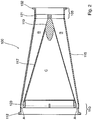
- fluid flow modifier device 100 Disposed between fluid supply pipe 15 and fluid treatment zone 25 is fluid flow modifier device 100. It will be seen that, externally, fluid flow modifier device 100 comprises a generally tapered shape to transition the flow from fluid supply pipe 15 to fluid treatment zone 25.
- fluid flow modifier device 100 The details of a particularly preferred embodiment of fluid flow modifier device 100 will be described with reference to Figures 2-5 .
- the fluid flow modifier device 100 comprises an inlet portion 105.
- Inlet portion 105 comprises a flange plate 102 to be secured to a complementary flange plate (not shown) which forms part of fluid supply pipe 15.
- Outlet portion 110 comprises a flange plate 112 which is configured to connect to the complementary flange plate (not shown) on fluid treatment zone 25.
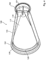
- a tapered outer flow transition portion 115 Disposed between inlet portion 105 and outlet 110 is a tapered outer flow transition portion 115. Disposed within outer flow transition portion 115 is an inner porous flow transition element 117.
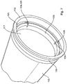
- inner porous portion 117 is supported by an inlet support nose 119 which in turn is supported by a nose support element 121 which is secured (e.g,. by welding) to an inside portion of inlet portion 105.
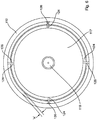
- inner porous portion 117 is supported by an inner support ring 123 which is secured to a support structure 125 that itself is secured (e.g., by welding) to an inner portion outlet portion 110. More particularly, inner support ring 123 comprises a series a slots 124 which are configured to engage a series of tabs 126 disposed on support structure 125.
- support ring 123 and support structure 125 cooperate to define an annular gap A therebetween - this permits a portion of the fluid entering fluid flow modifier device 100 to pass annularly between outer flow transition portion 115 and inner porous portion 117. The rest of the fluid entering fluid flow modifier device 100 must pass through inner porous 117 to reach outlet portion 110.
- the provision of gap A allows for provision of a pressure release at the transition which substantially assists in preventing jetting and turbulent flow.
- gap A is adjustable depending on the flow dynamics of the particular system in which fluid flow modifier device 100 is installed.
- inner porous portion 117 provides a relatively high fluid pressure zone B upstream thereof and a relatively low fluid pressure C downstream thereof.
- inner porous portion 117 may be varied depending on the specific application of fluid flow modifier device 100.
- inner porous portion 117 may be made from mesh, wires, perforated metal and the like.
- the porosity of inner porous portion 117 is preferably as specified above.
- a fluid flow modifier device having a combination of elements described above allows for the overall length of device 100 to be relatively short.
- the overall length of fluid flow modifier device 100 is less than or equal to 3.5 times the inner diameter of outlet portion 110 which typically corresponds to the inner diameter an inlet of the fluid treatment zone downstream of fluid flow modifier device 100.
- a fluid flow modifier device may comprise the following features:
- a fluid treatment system comprising a fluid inlet, a fluid outlet and a fluid treatment zone disposed between the fluid inlet and the fluid outlet, the inlet portion of the fluid flow modifier device being coupled to the fluid inlet of the fluid treatment system.
Landscapes
- Engineering & Computer Science (AREA)
- General Engineering & Computer Science (AREA)
- Physics & Mathematics (AREA)
- Fluid Mechanics (AREA)
- Mechanical Engineering (AREA)
- Environmental & Geological Engineering (AREA)
- Water Supply & Treatment (AREA)
- Life Sciences & Earth Sciences (AREA)
- Toxicology (AREA)
- Chemical & Material Sciences (AREA)
- Hydrology & Water Resources (AREA)
- Organic Chemistry (AREA)
- Health & Medical Sciences (AREA)
- Physical Or Chemical Processes And Apparatus (AREA)
- Physical Water Treatments (AREA)
- Flow Control (AREA)
Claims (14)
- Fluidstrommodifikator- (100) Vorrichtung, umfassend:einen Einlassteil (105) zum Empfangen eines Fluidstroms;einen Auslassteil (110) zum Ausgeben des Fluidstroms;einen Strommodifikatorteil, der zwischen dem Einlassteil (105) und dem Auslassteil (110) angeordnet ist, wobei der Strommodifikatorteil umfasst: (i) einen äußeren Teil, der einen geschlossenen Querschnitt zum Fluidstrom umfasst; (ii) einen inneren porösen Teil (117), der derart konfiguriert ist, dass mindestens ein Teil des im Einlassteil (105) empfangenen Stroms durch den inneren porösen Teil (117) laufen muss, um den Fluidauslass zu erreichen; (iii) ein erstes Trägerelement, das dazu konfiguriert ist, einen stromaufwärtigen Teil des inneren porösen Teils (117) in Bezug auf den äußeren Teil (110) zu tragen; und (iv) ein zweites Trägerelement, das dazu konfiguriert ist, einen stromabwärtigen Teil des inneren porösen Teils (117) in Bezug auf den äußeren Teil zu tragen, wobei das zweite Trägerelement dazu konfiguriert ist, einen ringförmigen Spalt (A) zwischen einem stromabwärtigen Teil des inneren porösen Teils (117) und dem äußeren Teil zu definieren, derart, dass ein Teil von Fluid, welches in die Fluidstrommodifikator-Vorrichtung eintritt, durch den ringförmigen Spalt (A) läuft; wobei der geschlossene Querschnitt des äußeren Teils orthogonal zu einer durch den Einlassteil (105) und den Auslassteil (110) laufenden Mittelachse vom Einlassteil (105) zum Auslassteil (110) hin zunimmt.
- Fluidstrommodifikator-Vorrichtung (100) nach Anspruch 1, wobei der äußere Teil des Strommodifikatorteils verjüngt ist.
- Fluidstrommodifikator-Vorrichtung (100) nach Ansprüchen 1 oder 2, wobei der innere poröse Teil (117) in Bezug auf den äußeren Teil freitragend ist.
- Fluidstrommodifikator-Vorrichtung (100) nach Anspruch 1, wobei das erste Trägerelement und der äußere Teil im Wesentlichen die gleiche Querschnittsform aufweisen.
- Fluidstrommodifikator-Vorrichtung (100) nach Anspruch 1, wobei der Spalt (A) im Bereich von etwa 1,52 mm [0,060 Zoll] bis etwa 38,10 mm [1,500 Zoll] beträgt.
- Fluidstrommodifikator-Vorrichtung (100) nach Ansprüchen 1-5, wobei der innere poröse Teil (117) einen offenen Gesamtflächeninhalt im Bereich von etwa 25 % bis etwa 75 % des Gesamtflächeninhalts des inneren porösen Teils (117) aufweist.
- Fluidstrommodifikator-Vorrichtung (100) nach Ansprüchen 1-6, wobei der innere poröse Teil (117) einen offenen Gesamtflächeninhalt im Bereich von etwa 40 % bis etwa 60 % des Gesamtflächeninhalts des inneren porösen Teils (117) aufweist.
- Fluidstrommodifikator-Vorrichtung (100) nach Ansprüchen 1-7, wobei die Fluidstrommodifikator-Vorrichtung länglich ist und eine Länge von weniger als oder gleich etwa 2,5-mal einem Innendurchmesser des Auslassteils (110) aufweist.
- Fluidstrommodifikator-Vorrichtung (100) nach Ansprüchen 1-8, wobei jeder aus dem äußeren Teil und dem inneren porösen Teil (117) eine im Wesentlichen sich verjüngende Konfiguration aufweist.
- Fluidstrommodifikator-Vorrichtung (100) nach Anspruch 9, wobei: (a) der äußere Teil einen ersten Verjüngungswinkel im Bereich von etwa 5° bis etwa 20° zwischen (i) einer durch den Einlassteil (105) und den Auslassteil (110) laufenden Mittelachse, und (ii) einer Wand des äußeren Teils umfasst, und (b) der innere poröse Teil (117) einen zweiten Verjüngungswinkel im Bereich von etwa 8° bis etwa 30° zwischen (i) einer durch den Einlassteil (105) und den Auslassteil (110) laufenden Mittelachse, und (ii) einer Wand des äußeren Teils umfasst.
- Fluidstrommodifikator-Vorrichtung (100) nach Anspruch 10, wobei der zweite Verjüngungswinkel größer ist als der erste Verjüngungswinkel.
- Fluidstrommodifikator-Vorrichtung (100) nach Ansprüchen 1-11, wobei der äußere Teil und der innere poröse Teil (117) in einer im Wesentlichen koaxialen Beziehung in Bezug auf eine durch den Einlassteil (105) und den Auslassteil (110) laufende Mittelachse ausgerichtet sind.
- Fluidbehandlungssystem (10), welches die Fluidstrommodifikator-Vorrichtung nach Ansprüchen 1-12 umfasst, wobei der Einlassteil (105) der Fluidstrommodifikator-Vorrichtung (100) mit dem Fluideinlass des Fluidbehandlungssystems (10) gekoppelt ist.
- Fluidbehandlungssystem (10), welches die Fluidstrommodifikator-Vorrichtung nach Ansprüchen 1-12 umfasst, Strahlenquellenanordnungen, die zwischen dem Fluideinlass und dem Fluidauslass angeordnet sind, wobei der Einlassteil (105) der Fluidstrommodifikator-Vorrichtung (100) mit dem Fluideinlass des Fluidbehandlungssystems (10) gekoppelt ist.
Applications Claiming Priority (2)
| Application Number | Priority Date | Filing Date | Title |
|---|---|---|---|
| US201261632210P | 2012-01-20 | 2012-01-20 | |
| PCT/CA2013/000043 WO2013106914A1 (en) | 2012-01-20 | 2013-01-21 | Fluid flow modifier and fluid treatment system incorporating same |
Publications (3)
| Publication Number | Publication Date |
|---|---|
| EP2805064A1 EP2805064A1 (de) | 2014-11-26 |
| EP2805064A4 EP2805064A4 (de) | 2015-09-30 |
| EP2805064B1 true EP2805064B1 (de) | 2018-09-12 |
Family
ID=48798443
Family Applications (1)
| Application Number | Title | Priority Date | Filing Date |
|---|---|---|---|
| EP13738372.5A Not-in-force EP2805064B1 (de) | 2012-01-20 | 2013-01-21 | Flüssigkeitsflussmodifikator und flüssigkeitsverarbeitungssystem damit |
Country Status (5)
| Country | Link |
|---|---|
| US (1) | US9771959B2 (de) |
| EP (1) | EP2805064B1 (de) |
| CN (1) | CN104145122A (de) |
| CA (1) | CA2861879A1 (de) |
| WO (1) | WO2013106914A1 (de) |
Families Citing this family (9)
| Publication number | Priority date | Publication date | Assignee | Title |
|---|---|---|---|---|
| US11493066B2 (en) * | 2016-01-20 | 2022-11-08 | Soliton Holdings | Generalized jet-effect and enhanced devices |
| CN105946340B (zh) * | 2016-06-15 | 2018-01-19 | 湖州惠盛机械有限公司 | 一种圆网印花机色浆输送泵 |
| US10309432B2 (en) * | 2016-06-22 | 2019-06-04 | Fmc Technologies, Inc. | Flow conditioner |
| DE102016220527A1 (de) | 2016-10-19 | 2018-04-19 | Wilhelm Bruckbauer | Bogenelement für ein Lüftungssystem |
| US10829228B2 (en) | 2017-01-17 | 2020-11-10 | Itt Manufacturing Enterprises, Llc | Fluid straightening connection unit |
| DK201800178A1 (en) | 2018-04-23 | 2019-10-30 | Ultraaqua A/S | Method and device for improving the efficiency of treating fluids applied to a UV reactor. |
| CN111206654A (zh) * | 2020-01-18 | 2020-05-29 | 顾地科技股份有限公司 | 一种消音排水管及连接管头 |
| US11578738B1 (en) * | 2022-06-22 | 2023-02-14 | Yongzhen Du | Vortex water flow accelerator |
| CN115355387A (zh) * | 2022-08-09 | 2022-11-18 | 深圳融昕医疗科技有限公司 | 分流件、分流组件、匀流模组以及匀流设备 |
Citations (1)
| Publication number | Priority date | Publication date | Assignee | Title |
|---|---|---|---|---|
| DE102010047782B3 (de) * | 2010-10-08 | 2012-01-12 | Itt Manufacturing Enterprises, Inc. | Strömungsgleichrichter für geschlossene Rohrleitungen |
Family Cites Families (24)
| Publication number | Priority date | Publication date | Assignee | Title |
|---|---|---|---|---|
| US2185584A (en) | 1940-01-02 | Muffler | ||
| US1666257A (en) * | 1925-09-17 | 1928-04-17 | Furnivall William Henry Graham | Exhaust silencer |
| US2090719A (en) * | 1935-12-26 | 1937-08-24 | Alt Karl | Form of pipe coupling |
| US3154388A (en) * | 1962-09-07 | 1964-10-27 | Universal Oil Prod Co | Converter-muffler |
| US3519708A (en) | 1966-11-21 | 1970-07-07 | Dow Chemical Co | Method of forming selectively permeable bodies from flexible polyurethane foam |
| GB1307533A (en) * | 1970-01-15 | 1973-02-21 | Dunlop Holdings Ltd | Pressure reducing devices |
| US3672465A (en) * | 1970-10-15 | 1972-06-27 | Blatt Leland F | Gas exhaust silencer |
| ZA717136B (en) * | 1970-11-06 | 1972-07-26 | Dunlop Holdings Ltd | Pressure reducing device |
| DE2436456A1 (de) * | 1974-07-29 | 1976-02-12 | Siemens Ag | Verteiler fuer stroemende medien |
| CA1163086A (en) | 1981-11-30 | 1984-03-06 | Jan Maarschalkerweerd | Ultraviolet fluid purifying device |
| US4872980A (en) | 1988-09-13 | 1989-10-10 | Trojan Technologies, Inc. | Fluid purification device |
| US5006244A (en) | 1988-09-13 | 1991-04-09 | Trojan Technologies, Inc. | Fluid purification device |
| USRE36896E (en) | 1993-03-05 | 2000-10-03 | Trojan Technologies Inc. | Fluid treatment system and process |
| US5418370A (en) | 1993-03-05 | 1995-05-23 | Trojan Technologies, Inc. | Fluid treatment system and process |
| US5511585A (en) | 1994-03-31 | 1996-04-30 | The Lee Company | Method and device for providing fluid resistance within a flow passageway |
| US5504335A (en) | 1994-10-17 | 1996-04-02 | Trojan Technologies, Inc. | Fluid treatment device and method |
| AU4530600A (en) | 1999-05-05 | 2000-11-21 | Noel K. Douglas | Method and apparatus for fluid treatment by uv-radiation |
| US6089346A (en) * | 1999-06-02 | 2000-07-18 | 3M Innovative Properties Company | Muffler with acoustic barrier material for limited clearance pneumatic device applications |
| US6500346B1 (en) | 1999-10-01 | 2002-12-31 | Trojan Technologies, Inc. | Fluid treatment device and method for treatment of fluid |
| JP2004036784A (ja) | 2002-07-04 | 2004-02-05 | Mitsubishi Heavy Ind Ltd | 偏流防止装置 |
| WO2005087277A1 (en) | 2004-03-12 | 2005-09-22 | Trojan Technologies Inc. | Fluid treatment system |
| US7380397B2 (en) * | 2005-09-08 | 2008-06-03 | Chih-Kuang Chang | Automobile exhaust pipe assembly |
| US7905321B2 (en) * | 2007-02-12 | 2011-03-15 | Ballard Iii Ebbin C | Inserts for engine exhaust systems |
| US20080190689A1 (en) * | 2007-02-12 | 2008-08-14 | Ballard Ebbin C | Inserts for engine exhaust systems |
-
2013
- 2013-01-21 CA CA2861879A patent/CA2861879A1/en not_active Abandoned
- 2013-01-21 EP EP13738372.5A patent/EP2805064B1/de not_active Not-in-force
- 2013-01-21 US US14/373,487 patent/US9771959B2/en not_active Expired - Fee Related
- 2013-01-21 CN CN201380005988.4A patent/CN104145122A/zh active Pending
- 2013-01-21 WO PCT/CA2013/000043 patent/WO2013106914A1/en not_active Ceased
Patent Citations (1)
| Publication number | Priority date | Publication date | Assignee | Title |
|---|---|---|---|---|
| DE102010047782B3 (de) * | 2010-10-08 | 2012-01-12 | Itt Manufacturing Enterprises, Inc. | Strömungsgleichrichter für geschlossene Rohrleitungen |
Also Published As
| Publication number | Publication date |
|---|---|
| WO2013106914A1 (en) | 2013-07-25 |
| EP2805064A4 (de) | 2015-09-30 |
| US20140373955A1 (en) | 2014-12-25 |
| US9771959B2 (en) | 2017-09-26 |
| CN104145122A (zh) | 2014-11-12 |
| CA2861879A1 (en) | 2013-07-25 |
| EP2805064A1 (de) | 2014-11-26 |
Similar Documents
| Publication | Publication Date | Title |
|---|---|---|
| EP2805064B1 (de) | Flüssigkeitsflussmodifikator und flüssigkeitsverarbeitungssystem damit | |
| EP3111963B1 (de) | Flüssigkeitsbehandlungssystem mit länglichen strahlungsquelle-bauteilen | |
| EP2605848B1 (de) | Fluidfiltervorrichtung | |
| US9115009B2 (en) | Fluid treatment system | |
| WO2016110829A1 (en) | Radiation treatment system and method | |
| US20110006223A1 (en) | Radiation source assembly and fluid treatment system | |
| US7683354B2 (en) | Water treating reactor for the drinkability thereof | |
| US20070045197A1 (en) | UV disinfection systems with tangential inlets and methods thereof | |
| US9539351B2 (en) | Radiation source module and fluid treatment system | |
| NL1039050C2 (en) | Device and method for a uv disinfection reactor. | |
| US10322947B2 (en) | Radiation source cleaning system and module containing same | |
| KR20120003519U (ko) | 배관 삽입형 살균용 자외선 반응기의 uv램프 배열 구조 | |
| RU2006128673A (ru) | Центральная труба радиального каталитического реактора |
Legal Events
| Date | Code | Title | Description |
|---|---|---|---|
| PUAI | Public reference made under article 153(3) epc to a published international application that has entered the european phase |
Free format text: ORIGINAL CODE: 0009012 |
|
| 17P | Request for examination filed |
Effective date: 20140820 |
|
| AK | Designated contracting states |
Kind code of ref document: A1 Designated state(s): AL AT BE BG CH CY CZ DE DK EE ES FI FR GB GR HR HU IE IS IT LI LT LU LV MC MK MT NL NO PL PT RO RS SE SI SK SM TR |
|
| DAX | Request for extension of the european patent (deleted) | ||
| RA4 | Supplementary search report drawn up and despatched (corrected) |
Effective date: 20150901 |
|
| RIC1 | Information provided on ipc code assigned before grant |
Ipc: B01J 4/00 20060101ALI20150826BHEP Ipc: F15D 1/02 20060101AFI20150826BHEP Ipc: C02F 1/00 20060101ALI20150826BHEP Ipc: C02F 1/32 20060101ALI20150826BHEP |
|
| STAA | Information on the status of an ep patent application or granted ep patent |
Free format text: STATUS: EXAMINATION IS IN PROGRESS |
|
| 17Q | First examination report despatched |
Effective date: 20170323 |
|
| REG | Reference to a national code |
Ref country code: DE Ref legal event code: R079 Ref document number: 602013043535 Country of ref document: DE Free format text: PREVIOUS MAIN CLASS: F15D0001020000 Ipc: F15D0001040000 |
|
| RIC1 | Information provided on ipc code assigned before grant |
Ipc: F15D 1/00 20060101ALI20180215BHEP Ipc: F15D 1/02 20060101ALI20180215BHEP Ipc: C02F 1/32 20060101ALI20180215BHEP Ipc: F15D 1/04 20060101AFI20180215BHEP |
|
| GRAP | Despatch of communication of intention to grant a patent |
Free format text: ORIGINAL CODE: EPIDOSNIGR1 |
|
| STAA | Information on the status of an ep patent application or granted ep patent |
Free format text: STATUS: GRANT OF PATENT IS INTENDED |
|
| INTG | Intention to grant announced |
Effective date: 20180327 |
|
| GRAS | Grant fee paid |
Free format text: ORIGINAL CODE: EPIDOSNIGR3 |
|
| GRAA | (expected) grant |
Free format text: ORIGINAL CODE: 0009210 |
|
| STAA | Information on the status of an ep patent application or granted ep patent |
Free format text: STATUS: THE PATENT HAS BEEN GRANTED |
|
| AK | Designated contracting states |
Kind code of ref document: B1 Designated state(s): AL AT BE BG CH CY CZ DE DK EE ES FI FR GB GR HR HU IE IS IT LI LT LU LV MC MK MT NL NO PL PT RO RS SE SI SK SM TR |
|
| REG | Reference to a national code |
Ref country code: GB Ref legal event code: FG4D |
|
| REG | Reference to a national code |
Ref country code: CH Ref legal event code: EP |
|
| REG | Reference to a national code |
Ref country code: IE Ref legal event code: FG4D |
|
| REG | Reference to a national code |
Ref country code: DE Ref legal event code: R096 Ref document number: 602013043535 Country of ref document: DE |
|
| REG | Reference to a national code |
Ref country code: AT Ref legal event code: REF Ref document number: 1040941 Country of ref document: AT Kind code of ref document: T Effective date: 20181015 |
|
| REG | Reference to a national code |
Ref country code: NL Ref legal event code: MP Effective date: 20180912 |
|
| REG | Reference to a national code |
Ref country code: LT Ref legal event code: MG4D |
|
| PG25 | Lapsed in a contracting state [announced via postgrant information from national office to epo] |
Ref country code: RS Free format text: LAPSE BECAUSE OF FAILURE TO SUBMIT A TRANSLATION OF THE DESCRIPTION OR TO PAY THE FEE WITHIN THE PRESCRIBED TIME-LIMIT Effective date: 20180912 Ref country code: SE Free format text: LAPSE BECAUSE OF FAILURE TO SUBMIT A TRANSLATION OF THE DESCRIPTION OR TO PAY THE FEE WITHIN THE PRESCRIBED TIME-LIMIT Effective date: 20180912 Ref country code: BG Free format text: LAPSE BECAUSE OF FAILURE TO SUBMIT A TRANSLATION OF THE DESCRIPTION OR TO PAY THE FEE WITHIN THE PRESCRIBED TIME-LIMIT Effective date: 20181212 Ref country code: LT Free format text: LAPSE BECAUSE OF FAILURE TO SUBMIT A TRANSLATION OF THE DESCRIPTION OR TO PAY THE FEE WITHIN THE PRESCRIBED TIME-LIMIT Effective date: 20180912 Ref country code: GR Free format text: LAPSE BECAUSE OF FAILURE TO SUBMIT A TRANSLATION OF THE DESCRIPTION OR TO PAY THE FEE WITHIN THE PRESCRIBED TIME-LIMIT Effective date: 20181213 Ref country code: NO Free format text: LAPSE BECAUSE OF FAILURE TO SUBMIT A TRANSLATION OF THE DESCRIPTION OR TO PAY THE FEE WITHIN THE PRESCRIBED TIME-LIMIT Effective date: 20181212 Ref country code: FI Free format text: LAPSE BECAUSE OF FAILURE TO SUBMIT A TRANSLATION OF THE DESCRIPTION OR TO PAY THE FEE WITHIN THE PRESCRIBED TIME-LIMIT Effective date: 20180912 |
|
| PG25 | Lapsed in a contracting state [announced via postgrant information from national office to epo] |
Ref country code: HR Free format text: LAPSE BECAUSE OF FAILURE TO SUBMIT A TRANSLATION OF THE DESCRIPTION OR TO PAY THE FEE WITHIN THE PRESCRIBED TIME-LIMIT Effective date: 20180912 Ref country code: AL Free format text: LAPSE BECAUSE OF FAILURE TO SUBMIT A TRANSLATION OF THE DESCRIPTION OR TO PAY THE FEE WITHIN THE PRESCRIBED TIME-LIMIT Effective date: 20180912 Ref country code: LV Free format text: LAPSE BECAUSE OF FAILURE TO SUBMIT A TRANSLATION OF THE DESCRIPTION OR TO PAY THE FEE WITHIN THE PRESCRIBED TIME-LIMIT Effective date: 20180912 |
|
| REG | Reference to a national code |
Ref country code: AT Ref legal event code: MK05 Ref document number: 1040941 Country of ref document: AT Kind code of ref document: T Effective date: 20180912 |
|
| PG25 | Lapsed in a contracting state [announced via postgrant information from national office to epo] |
Ref country code: RO Free format text: LAPSE BECAUSE OF FAILURE TO SUBMIT A TRANSLATION OF THE DESCRIPTION OR TO PAY THE FEE WITHIN THE PRESCRIBED TIME-LIMIT Effective date: 20180912 Ref country code: IT Free format text: LAPSE BECAUSE OF FAILURE TO SUBMIT A TRANSLATION OF THE DESCRIPTION OR TO PAY THE FEE WITHIN THE PRESCRIBED TIME-LIMIT Effective date: 20180912 Ref country code: CZ Free format text: LAPSE BECAUSE OF FAILURE TO SUBMIT A TRANSLATION OF THE DESCRIPTION OR TO PAY THE FEE WITHIN THE PRESCRIBED TIME-LIMIT Effective date: 20180912 Ref country code: EE Free format text: LAPSE BECAUSE OF FAILURE TO SUBMIT A TRANSLATION OF THE DESCRIPTION OR TO PAY THE FEE WITHIN THE PRESCRIBED TIME-LIMIT Effective date: 20180912 Ref country code: IS Free format text: LAPSE BECAUSE OF FAILURE TO SUBMIT A TRANSLATION OF THE DESCRIPTION OR TO PAY THE FEE WITHIN THE PRESCRIBED TIME-LIMIT Effective date: 20190112 Ref country code: AT Free format text: LAPSE BECAUSE OF FAILURE TO SUBMIT A TRANSLATION OF THE DESCRIPTION OR TO PAY THE FEE WITHIN THE PRESCRIBED TIME-LIMIT Effective date: 20180912 Ref country code: NL Free format text: LAPSE BECAUSE OF FAILURE TO SUBMIT A TRANSLATION OF THE DESCRIPTION OR TO PAY THE FEE WITHIN THE PRESCRIBED TIME-LIMIT Effective date: 20180912 Ref country code: PL Free format text: LAPSE BECAUSE OF FAILURE TO SUBMIT A TRANSLATION OF THE DESCRIPTION OR TO PAY THE FEE WITHIN THE PRESCRIBED TIME-LIMIT Effective date: 20180912 Ref country code: ES Free format text: LAPSE BECAUSE OF FAILURE TO SUBMIT A TRANSLATION OF THE DESCRIPTION OR TO PAY THE FEE WITHIN THE PRESCRIBED TIME-LIMIT Effective date: 20180912 |
|
| PG25 | Lapsed in a contracting state [announced via postgrant information from national office to epo] |
Ref country code: PT Free format text: LAPSE BECAUSE OF FAILURE TO SUBMIT A TRANSLATION OF THE DESCRIPTION OR TO PAY THE FEE WITHIN THE PRESCRIBED TIME-LIMIT Effective date: 20190112 Ref country code: SM Free format text: LAPSE BECAUSE OF FAILURE TO SUBMIT A TRANSLATION OF THE DESCRIPTION OR TO PAY THE FEE WITHIN THE PRESCRIBED TIME-LIMIT Effective date: 20180912 Ref country code: SK Free format text: LAPSE BECAUSE OF FAILURE TO SUBMIT A TRANSLATION OF THE DESCRIPTION OR TO PAY THE FEE WITHIN THE PRESCRIBED TIME-LIMIT Effective date: 20180912 |
|
| REG | Reference to a national code |
Ref country code: DE Ref legal event code: R097 Ref document number: 602013043535 Country of ref document: DE |
|
| PLBE | No opposition filed within time limit |
Free format text: ORIGINAL CODE: 0009261 |
|
| STAA | Information on the status of an ep patent application or granted ep patent |
Free format text: STATUS: NO OPPOSITION FILED WITHIN TIME LIMIT |
|
| PG25 | Lapsed in a contracting state [announced via postgrant information from national office to epo] |
Ref country code: DK Free format text: LAPSE BECAUSE OF FAILURE TO SUBMIT A TRANSLATION OF THE DESCRIPTION OR TO PAY THE FEE WITHIN THE PRESCRIBED TIME-LIMIT Effective date: 20180912 |
|
| REG | Reference to a national code |
Ref country code: DE Ref legal event code: R119 Ref document number: 602013043535 Country of ref document: DE |
|
| 26N | No opposition filed |
Effective date: 20190613 |
|
| PG25 | Lapsed in a contracting state [announced via postgrant information from national office to epo] |
Ref country code: SI Free format text: LAPSE BECAUSE OF FAILURE TO SUBMIT A TRANSLATION OF THE DESCRIPTION OR TO PAY THE FEE WITHIN THE PRESCRIBED TIME-LIMIT Effective date: 20180912 Ref country code: MC Free format text: LAPSE BECAUSE OF FAILURE TO SUBMIT A TRANSLATION OF THE DESCRIPTION OR TO PAY THE FEE WITHIN THE PRESCRIBED TIME-LIMIT Effective date: 20180912 |
|
| REG | Reference to a national code |
Ref country code: CH Ref legal event code: PL |
|
| GBPC | Gb: european patent ceased through non-payment of renewal fee |
Effective date: 20190121 |
|
| PG25 | Lapsed in a contracting state [announced via postgrant information from national office to epo] |
Ref country code: LU Free format text: LAPSE BECAUSE OF NON-PAYMENT OF DUE FEES Effective date: 20190121 |
|
| REG | Reference to a national code |
Ref country code: BE Ref legal event code: MM Effective date: 20190131 |
|
| REG | Reference to a national code |
Ref country code: IE Ref legal event code: MM4A |
|
| PG25 | Lapsed in a contracting state [announced via postgrant information from national office to epo] |
Ref country code: DE Free format text: LAPSE BECAUSE OF NON-PAYMENT OF DUE FEES Effective date: 20190801 Ref country code: FR Free format text: LAPSE BECAUSE OF NON-PAYMENT OF DUE FEES Effective date: 20190131 |
|
| PG25 | Lapsed in a contracting state [announced via postgrant information from national office to epo] |
Ref country code: BE Free format text: LAPSE BECAUSE OF NON-PAYMENT OF DUE FEES Effective date: 20190131 |
|
| PG25 | Lapsed in a contracting state [announced via postgrant information from national office to epo] |
Ref country code: LI Free format text: LAPSE BECAUSE OF NON-PAYMENT OF DUE FEES Effective date: 20190131 Ref country code: CH Free format text: LAPSE BECAUSE OF NON-PAYMENT OF DUE FEES Effective date: 20190131 Ref country code: GB Free format text: LAPSE BECAUSE OF NON-PAYMENT OF DUE FEES Effective date: 20190121 |
|
| PG25 | Lapsed in a contracting state [announced via postgrant information from national office to epo] |
Ref country code: IE Free format text: LAPSE BECAUSE OF NON-PAYMENT OF DUE FEES Effective date: 20190121 |
|
| PG25 | Lapsed in a contracting state [announced via postgrant information from national office to epo] |
Ref country code: TR Free format text: LAPSE BECAUSE OF FAILURE TO SUBMIT A TRANSLATION OF THE DESCRIPTION OR TO PAY THE FEE WITHIN THE PRESCRIBED TIME-LIMIT Effective date: 20180912 |
|
| PG25 | Lapsed in a contracting state [announced via postgrant information from national office to epo] |
Ref country code: MT Free format text: LAPSE BECAUSE OF NON-PAYMENT OF DUE FEES Effective date: 20190121 |
|
| PG25 | Lapsed in a contracting state [announced via postgrant information from national office to epo] |
Ref country code: CY Free format text: LAPSE BECAUSE OF FAILURE TO SUBMIT A TRANSLATION OF THE DESCRIPTION OR TO PAY THE FEE WITHIN THE PRESCRIBED TIME-LIMIT Effective date: 20180912 |
|
| PG25 | Lapsed in a contracting state [announced via postgrant information from national office to epo] |
Ref country code: HU Free format text: LAPSE BECAUSE OF FAILURE TO SUBMIT A TRANSLATION OF THE DESCRIPTION OR TO PAY THE FEE WITHIN THE PRESCRIBED TIME-LIMIT; INVALID AB INITIO Effective date: 20130121 |
|
| PG25 | Lapsed in a contracting state [announced via postgrant information from national office to epo] |
Ref country code: MK Free format text: LAPSE BECAUSE OF FAILURE TO SUBMIT A TRANSLATION OF THE DESCRIPTION OR TO PAY THE FEE WITHIN THE PRESCRIBED TIME-LIMIT Effective date: 20180912 |