US9539351B2 - Radiation source module and fluid treatment system - Google Patents
Radiation source module and fluid treatment system Download PDFInfo
- Publication number
- US9539351B2 US9539351B2 US13/994,941 US201113994941A US9539351B2 US 9539351 B2 US9539351 B2 US 9539351B2 US 201113994941 A US201113994941 A US 201113994941A US 9539351 B2 US9539351 B2 US 9539351B2
- Authority
- US
- United States
- Prior art keywords
- fluid
- radiation source
- fluid treatment
- wall surface
- treatment system
- Prior art date
- Legal status (The legal status is an assumption and is not a legal conclusion. Google has not performed a legal analysis and makes no representation as to the accuracy of the status listed.)
- Active, expires
Links
- 239000012530 fluid Substances 0.000 title claims abstract description 295
- 230000005855 radiation Effects 0.000 title claims abstract description 180
- 230000008878 coupling Effects 0.000 claims abstract description 6
- 238000010168 coupling process Methods 0.000 claims abstract description 6
- 238000005859 coupling reaction Methods 0.000 claims abstract description 6
- 230000000712 assembly Effects 0.000 claims description 24
- 238000000429 assembly Methods 0.000 claims description 24
- 238000004891 communication Methods 0.000 claims description 7
- 238000012986 modification Methods 0.000 description 10
- 230000004048 modification Effects 0.000 description 10
- 238000013519 translation Methods 0.000 description 7
- 238000011144 upstream manufacturing Methods 0.000 description 7
- XLYOFNOQVPJJNP-UHFFFAOYSA-N water Substances O XLYOFNOQVPJJNP-UHFFFAOYSA-N 0.000 description 7
- 238000000605 extraction Methods 0.000 description 6
- 238000013459 approach Methods 0.000 description 5
- 238000004140 cleaning Methods 0.000 description 5
- 230000001681 protective effect Effects 0.000 description 5
- 238000013461 design Methods 0.000 description 4
- 230000005484 gravity Effects 0.000 description 4
- 230000006872 improvement Effects 0.000 description 3
- 239000007788 liquid Substances 0.000 description 3
- 238000003491 array Methods 0.000 description 2
- 230000008901 benefit Effects 0.000 description 2
- 230000008859 change Effects 0.000 description 2
- 239000003651 drinking water Substances 0.000 description 2
- 230000000694 effects Effects 0.000 description 2
- 238000009434 installation Methods 0.000 description 2
- 239000000463 material Substances 0.000 description 2
- 230000000116 mitigating effect Effects 0.000 description 2
- 239000010841 municipal wastewater Substances 0.000 description 2
- 230000002829 reductive effect Effects 0.000 description 2
- 230000002411 adverse Effects 0.000 description 1
- 235000012206 bottled water Nutrition 0.000 description 1
- 238000005266 casting Methods 0.000 description 1
- 230000002860 competitive effect Effects 0.000 description 1
- 239000012141 concentrate Substances 0.000 description 1
- 238000011161 development Methods 0.000 description 1
- 235000020188 drinking water Nutrition 0.000 description 1
- 230000000670 limiting effect Effects 0.000 description 1
- 238000012423 maintenance Methods 0.000 description 1
- 239000010453 quartz Substances 0.000 description 1
- 238000009877 rendering Methods 0.000 description 1
- VYPSYNLAJGMNEJ-UHFFFAOYSA-N silicon dioxide Inorganic materials O=[Si]=O VYPSYNLAJGMNEJ-UHFFFAOYSA-N 0.000 description 1
- 230000001954 sterilising effect Effects 0.000 description 1
- 238000004659 sterilization and disinfection Methods 0.000 description 1
- 238000002834 transmittance Methods 0.000 description 1
- 239000002351 wastewater Substances 0.000 description 1
- 238000004065 wastewater treatment Methods 0.000 description 1
Images


Classifications
-
- A—HUMAN NECESSITIES
- A61—MEDICAL OR VETERINARY SCIENCE; HYGIENE
- A61L—METHODS OR APPARATUS FOR STERILISING MATERIALS OR OBJECTS IN GENERAL; DISINFECTION, STERILISATION OR DEODORISATION OF AIR; CHEMICAL ASPECTS OF BANDAGES, DRESSINGS, ABSORBENT PADS OR SURGICAL ARTICLES; MATERIALS FOR BANDAGES, DRESSINGS, ABSORBENT PADS OR SURGICAL ARTICLES
- A61L2/00—Methods or apparatus for disinfecting or sterilising materials or objects other than foodstuffs or contact lenses; Accessories therefor
- A61L2/02—Methods or apparatus for disinfecting or sterilising materials or objects other than foodstuffs or contact lenses; Accessories therefor using physical phenomena
- A61L2/08—Radiation
- A61L2/10—Ultra-violet radiation
-
- C—CHEMISTRY; METALLURGY
- C02—TREATMENT OF WATER, WASTE WATER, SEWAGE, OR SLUDGE
- C02F—TREATMENT OF WATER, WASTE WATER, SEWAGE, OR SLUDGE
- C02F1/00—Treatment of water, waste water, or sewage
- C02F1/30—Treatment of water, waste water, or sewage by irradiation
- C02F1/32—Treatment of water, waste water, or sewage by irradiation with ultraviolet light
- C02F1/325—Irradiation devices or lamp constructions
-
- C—CHEMISTRY; METALLURGY
- C02—TREATMENT OF WATER, WASTE WATER, SEWAGE, OR SLUDGE
- C02F—TREATMENT OF WATER, WASTE WATER, SEWAGE, OR SLUDGE
- C02F2201/00—Apparatus for treatment of water, waste water or sewage
- C02F2201/32—Details relating to UV-irradiation devices
- C02F2201/322—Lamp arrangement
- C02F2201/3225—Lamps immersed in an open channel, containing the liquid to be treated
-
- C—CHEMISTRY; METALLURGY
- C02—TREATMENT OF WATER, WASTE WATER, SEWAGE, OR SLUDGE
- C02F—TREATMENT OF WATER, WASTE WATER, SEWAGE, OR SLUDGE
- C02F2201/00—Apparatus for treatment of water, waste water or sewage
- C02F2201/32—Details relating to UV-irradiation devices
- C02F2201/322—Lamp arrangement
- C02F2201/3227—Units with two or more lamps
-
- C—CHEMISTRY; METALLURGY
- C02—TREATMENT OF WATER, WASTE WATER, SEWAGE, OR SLUDGE
- C02F—TREATMENT OF WATER, WASTE WATER, SEWAGE, OR SLUDGE
- C02F2201/00—Apparatus for treatment of water, waste water or sewage
- C02F2201/32—Details relating to UV-irradiation devices
- C02F2201/324—Lamp cleaning installations, e.g. brushes
-
- C—CHEMISTRY; METALLURGY
- C02—TREATMENT OF WATER, WASTE WATER, SEWAGE, OR SLUDGE
- C02F—TREATMENT OF WATER, WASTE WATER, SEWAGE, OR SLUDGE
- C02F2201/00—Apparatus for treatment of water, waste water or sewage
- C02F2201/32—Details relating to UV-irradiation devices
- C02F2201/328—Having flow diverters (baffles)
Definitions
- the present invention relates to a radiation source module for use in a fluid treatment system. In another of its aspects, the present invention relates to a fluid treatment system incorporating a radiation source module.
- Fluid treatment systems are generally known in the art. More particularly, ultraviolet (UV) radiation fluid treatment systems are generally known in the art.
- UV radiation fluid treatment systems are generally known in the art.
- Such systems include an array of UV lamp modules (e.g., frames) which include several UV lamps each of which are mounted within sleeves which extend between and are supported by a pair of legs which are attached to a cross-piece.
- the so-supported sleeves (containing the UV lamps) are immersed into a fluid to be treated which is then irradiated as required.
- the amount of radiation to which the fluid is exposed is determined by the proximity of the fluid to the lamps, the output wattage of the lamps and the flow rate of the fluid past the lamps.
- one or more UV sensors may be employed to monitor the UV output of the lamps and the fluid level is typically controlled, to some extent, downstream of the treatment device by means of level gates or the like.
- the Maarschalkerweerd #1 patents teach fluid treatment systems which were characterized by improved ability to extract the equipment from a wetted or submerged state without the need for full equipment redundancy. These designs compartmentalized the lamp arrays into rows and/or columns and were characterized by having the top of the reactor open to provide free-surface flow of fluid in a “top open” channel.
- the fluid treatment system taught in the Maarschalkerweerd #1 patents is characterized by having a free-surface flow of fluid (typically the top fluid surface was not purposely controlled or constrained).
- a free-surface flow of fluid typically the top fluid surface was not purposely controlled or constrained.
- the systems would typically follow the behaviour of open channel hydraulics. Since the design of the system inherently comprised a free-surface flow of fluid, there were constraints on the maximum flow each lamp or lamp array could handle before either one or other hydraulically adjoined arrays would be adversely affected by changes in water elevation. At higher flows or significant changes in the flow, the unrestrained or free-surface flow of fluid would be allowed to change the treatment volume and cross-sectional shape of the fluid flow, thereby rendering the reactor relatively ineffective.
- the improved radiation source module comprises a radiation source assembly (typically comprising a radiation source and a protective (e.g., quartz) sleeve) sealingly cantilevered from a support member.
- the support member may further comprise appropriate means to secure the radiation source module in the gravity fed fluid treatment system.
- the Maarschalkerweerd #2 patents are characterized by having a closed surface confining the fluid being treated in the treatment area of the reactor.
- This closed treatment system had open ends which, in effect, were disposed in an open channel.
- the submerged or wetted equipment UV lamps, cleaners and the like
- pivoted hinges, sliders and various other devices allowing removal of equipment from the semi-enclosed reactor to the free surfaces.
- the fluid treatment system described in the Maarschalkerweerd #2 patents was typically characterized by relatively short length lamps which were cantilevered to a substantially vertical support arm (i.e., the lamps were supported at one end only). This allowed for pivoting or other extraction of the lamp from the semi-enclosed reactor. These significantly shorter and more powerful lamps inherently are characterized by being less efficient in converting electrical energy to UV energy. The cost associated with the equipment necessary to physically access and support these lamps was significant.
- Maarschalkerweerd #3 teaches a closed fluid treatment device comprising a housing for receiving a flow of fluid.
- the housing comprises a fluid inlet, a fluid outlet, a fluid treatment zone disposed between the fluid inlet and the fluid outlet, and at least one radiation source module disposed in the fluid treatment zone.
- the fluid inlet, the fluid outlet and the fluid treatment zone are in a collinear relationship with respect to one another.
- the at least one radiation source module comprises a radiation source sealably connected to a leg which is sealably mounted to the housing.
- the radiation source is disposed substantially parallel to the flow of fluid.
- the radiation source module is removable through an aperture provided in the housing intermediate to fluid inlet and the fluid outlet thereby obviating the need to physically remove the device for service of the radiation source.
- U.S. Pat. No. 6,500,346 also teaches a closed fluid treatment device, particularly useful for ultraviolet radiation treatment of fluids such as water.
- the device comprises a housing for receiving a flow of fluid.
- the housing has a fluid inlet, a fluid outlet, a fluid treatment zone disposed between the fluid inlet and the fluid outlet and at least one radiation source having a longitudinal axis disposed in the fluid treatment zone substantially transverse to a direction of the flow of fluid through the housing.
- the fluid inlet, the fluid outlet and the fluid treatment zone are arranged substantially collinearly with respect to one another.
- the fluid inlet has a first opening having: (i) a cross-sectional area less than a cross-sectional area of the fluid treatment zone, and (ii) a largest diameter substantially parallel to the longitudinal axis of the at least one radiation source assembly.
- arrangement (ii) in a UV radiation water treatment system has been based on the theory that radiation was effective up to a prescribed distance from the radiation source, depending on the transmittance of the water being treated. Thus, it has become commonplace to interspace the radiation sources in arrangement (ii) such that the longitudinal axes of adjacent radiation sources are spaced at a distance equal to approximately twice the prescribed distance mentioned in the previous sentence.
- U.S. Pat. No. 5,503,800 [Free] teaches an ultraviolet sterilizing system for waste water adopting arrangement (ii) described above.
- channels are formed around a single lamp assembly and projections are formed in the channels to induce turbulent plug flow such that when the apparatus is inserted into a flow of liquid to be treated, the channels act to confine and direct liquid about the housing and the projections act to establish a continuous, cyclical flow in the channels between housing and the channels walls.
- This system has disadvantages since it requires individual channels be provided between a wall structure and a single lamp assembly. Thus, when treating large volumes of water, it is necessary to utilize a plurality of radiation source assemblies.
- U.S. Pat. No. 5,952,663 [Blatchley, III et al. (Blatchley)] teaches an apparatus for applying ultraviolet radiation dosage to fluids in an open channel.
- a fluid treatment channel containing a module having a series of vertically disposed lamps ( 14 ).
- Disposed on the sidewalls of the fluid channel are a series of fluid diverters ( 27 ).
- the arrangement of fluid diverters ( 27 ) is such that each fluid diverter ( 27 ) projects into the fluid treatment channel to the same extent.
- Such an arrangement is disadvantages since it results in relatively high fluid head loss and low treatment efficiency.
- the present fluid treatment systems uses a combination of the radiation source assembly and a prescribed wall structure to encourage fluid flow along the sides of the walls of the fluid treatment zone while obviating or mitigating short circuiting (i.e., the phenomon where fluid travel along the wall is not subject to a sufficient dose of radiation).
- fluid treatment system taught by Ma relies on relatively uniform fluid flow from side to side in the fluid treatment zone while obviating or mitigating short circuiting.
- the present invention provides a radiation source module for use in a fluid treatment system, the radiation source module comprising:
- a housing having an inlet, an outlet and a fluid treatment zone disposed between; the fluid treatment zone comprising a first wall surface and a second wall surface interconnected by a floor surface, the first wall surface, the second wall surface and the floor surface configured to received a flow of fluid through the fluid treatment zone;
- At least one radiation source assembly secured with respect to the first wall surface and the second wall surface;
- a module motive coupling element connected to the housing and configured to be coupled to a module motive element to permit the radiation source module to be installed in and extracted from the fluid treatment system
- the present invention provides a fluid treatment system comprising:
- At least one radiation source module comprising:
- the present inventors have discovered a novel radiation source module which obviates or mitigates the above-disadvantages of the prior art.
- the present radiation source module is, on the one hand, moveable in and out of the open channel in which fluid is flowing, while on the other hand, able to act as an independent fluid treatment system in that it contains sidewalls and a floor element which cooperate to contain a flow of fluid in which radiation source assemblies are disposed. While many of the embodiments disclosed below utilize distinct sidewalls and floor portions in the radiation source module to achieve this goal, it will be appreciated by those of skill in the art that the use of sidewalls and floor elements is not particularly required and, for example, a cross-sectional shape of the treatment area of the radiation source module could be somewhat continuous or curvilinear so as not to contain distinct sidewalls and floor elements yet still function in accordance with the teachings of the present invention. Such modifications are of course encompassed by the present invention.
- the illustrated embodiments below result in fluid passing through the radiation source module and being unconstrained on an upper surface of the fluid flowing through the radiation source module.
- These embodiments may be modified to provide a fluid radiation source module in which all surfaces of the fluid travelling there through are confined thereby presenting a substantially closed cross-section to the flow of fluid. Again, these modifications are encompassed by the present invention.
- module removal devices are illustrated which remove the radiation source module from the fluid treatment system by rotation or linear translation.
- rotation or linear translation it may be possible to modify these specific embodiments to achieve removal of the radiation source module without relying only on rotation or linear translation. Again, these modifications are encompassed by the present invention.
- FIGS. 1-21 illustrate various preferred embodiments of the present fluid treatment system and the present radiation source module.
- the present invention relates to a radiation source module for use in a fluid treatment system, the radiation source module comprising:
- a housing having an inlet, an outlet and a fluid treatment zone disposed between; the fluid treatment zone comprising a first wall surface and a second wall surface interconnected by a floor surface, the first wall surface, the second wall surface and the floor surface configured to received a flow of fluid through the fluid treatment zone;
- At least one radiation source assembly secured with respect to the first wall surface and the second wall surface;
- a module motive coupling element connected to the housing and configured to be coupled to a module motive element to permit the radiation source module to be installed in and extracted from the fluid treatment system.
- the present invention relates to a fluid treatment system comprising:
- At least one radiation source module comprising:
- Fluid treatment system 10 comprises an open channel 12 .
- Open channel 12 comprises a channel floor 14 and a pair of a channel side walls 16 .
- a bulkhead 18 Disposed in open channel 10 is a bulkhead 18 having an opening 20 . Surrounding opening 20 is a seal element 22 . A module removal device 24 is disposed on top of bulkhead 18 . An electrical control panel 26 is disposed to one side of open channel 10 . A series of grates 28 are disposed across open channel 10 near the top of channel side walls 16 .
- a pair of radiation source modules 100 are disposed in open channel 10 on either side of bulkhead 18 .
- the nature of radiation source modules 100 will be described in more detail below. As illustrated, upstream radiation source module 100 is partially withdrawn from its so-called “in use” position in open channel 10 whereas downstream radiation source module 100 is in a so-called “in use” position with respect to bulkhead 18 and open channel 12 .
- a flow of fluid typically gravity fed, enters open channel 12 and flows in the direction of arrows A resulting in a fluid level 30 .
- upstream radiation source module 100 is shown in a so-called “in use” position whereas downstream radiation source module 100 shown in FIG. 1 has not been shown for clarity purposes only.
- radiation source module 100 comprises a housing 105 .
- Housing 105 comprises a pair of module sidewalls 110 , 115 and a module floor 120 interconnecting module sidewalls 110 , 115 .
- Housing 105 further comprises a fluid inlet 125 and a fluid outlet 130 .
- module sidewalls 110 , 115 and module floor 120 combine to confine fluid entering housing 105 to define a fluid treatment zone. Disposed in this fluid treatment zone are a series of radiation source assemblies 135 . It can be seen that radiation source assemblies 135 have a longitudinal access which is disposed substantially transverse to the direction of fluid flow through open channel 12 of fluid treatment system 10 .
- a cleaning system 140 is coupled to radiation source assemblies 135 and is movable from a retracted position to an extended position to remove undesirable material from the exterior of radiation source assemblies 135 .
- module sidewall 110 of housing 105 is removable to allow access to radiation source assemblies 135 and cleaning system 140 .
- Module sidewall 115 and floor surface 120 is similarly removable but these are not shown for clarity purposes.
- Pivot elements 145 are connected to a hydraulic cylinder 150 which is connected to module removal device 24 .
- Seal element 155 Disposed around the periphery of fluid outlet 130 is a seal element 155 shown in FIG. 7 .
- Seal element 155 is positioned and dimensioned to cooperate with seal element 22 on bulkhead 18 to provide a substantial fluid tight seal between housing 105 and bulkhead 18 .
- sidewalls 110 , 115 are shown as being smooth, it is possible to modify the interior surface of these sidewalls to adopt one more fluid deflector elements and/or receptacles, for example, as described in Ma.
- housing 105 of radiation source module 100 acts as a small open channel fluid treatment system in that fluid level 30 a is unconstrained by any physical structure of radiation source module 100 .
- FIG. 4 With reference to FIG. 4 , when it is desired to extract radiation source module 100 from open channel 12 , hydraulic cylinder 150 shown in FIGS. 2 and 3 (not shown in FIG. 4 for clarity) is extended which has the effect of pivoting radiation source module 100 out of open channel 12 .
- FIG. 4 again for clarity, downstream radiation source module 100 shown in FIG. 1 has not been illustrated. See also FIG. 5 which shows the same view as FIG. 4 except in FIG. 5 , sidewall 110 of housing 105 of radiation source module 100 is shown in place.
- FIG. 6 illustrates a modification of the embodiment discussed above with reference to FIG. 5 .
- housing 105 of radiation source module 100 has been modified to include a pair of upstanding baffle plates 160 upstream and 165 downstream of the distal portions of radiation source assemblies 135 .
- baffle plates is discussed in more detail in co-pending International Patent Publication Number WO 2010/102383 A1.
- FIGS. 10-11 there is illustrated a modification to radiation source module 100 illustrated in FIGS. 1-9 .
- radiation source module 100 has been modified to rotate out of open channel 10 using a winch 200 (or similar element) and cable 205 disposed on a winch module 210 . All other aspects of fluid radiation system 10 and radiation source module 100 are similar to those discussed above.
- FIG. 12 there is shown an illustration of servicing of one or more radiation source assemblies 135 while radiation source module is maintained in position in open channel 12 .
- extraction of entire radiation source module 100 from open channel 12 is not required to service radiation source assemblies 135 .
- FIGS. 13-15 there is shown a modification of fluid treatment system 10 illustrative in FIG. 1 .
- bulkhead 18 in fluid treatment system 10 in FIG. 1 has been modified to include a prefabricated bulkhead U-shaped channel element 18 a which is disposed in a channel to form element 18 b attached to channel side walls 16 and channel floor 14 .
- a bulkhead sub-unit element 18 c is disposed in prefabricated bulkhead U-shaped channel element 18 a.
- FIGS. 13-15 may be more convenient and/or less costly than casting bulkhead element 18 shown in FIG. 1 .
- the details of fluid treatment system 10 and radiation source module 100 are otherwise similar to those discussed above.
- FIG. 15 illustrates a system without radiation source module 100 and the module removal device.
- FIG. 16 illustrates a modification of fluid treatment system 10 shown in FIG. 1 .
- a second bulkhead 18 d is disposed downstream of bulkhead 18 to provide for additional exposure of fluid in open channel 10 to radiation.
- Each of bulkheads 18 , 18 d are combined with a radiation source module 100 disposed upstream thereof—i.e., there is no radiation source module facing and contacting the downstream portion of bulkheads 18 , 18 d . All other details of fluid treatment system 10 and radiation source module 100 are similar to those described above.
- FIGS. 17-21 there is illustrated a modification to fluid treatment system 100 illustrated in FIG. 1 .
- the module removal device operates on the basis of linear translation instead of rotation.
- radiation source modules 100 are lifted in a relatively straight manner from open channel 12 .
- Module translation device 300 is movable along open channel 12 to move radiation source modules that are disposed upstream and downstream of bulkhead 18 . Disposed in open channel 12 is a bulkhead guiderail 310 . Module translation device 300 further comprises a winch 305 (or similar device) and a cable 308 for connection to radiation source module 100 .
- the shape of bulkhead 18 and housing 105 of radiation source module 100 have been modified to facilitate translation type movement of radiation source module 100 during extraction or installation thereof.
- radiation source module 100 has been modified to provide a module lifting eyelet 180 on top of housing 105 .
- Radiation source module 100 has been further modified to include a roller 190 that is disposed within bulkhead guiderail 310 .
Landscapes
- Health & Medical Sciences (AREA)
- Life Sciences & Earth Sciences (AREA)
- Chemical & Material Sciences (AREA)
- Engineering & Computer Science (AREA)
- Organic Chemistry (AREA)
- Water Supply & Treatment (AREA)
- Environmental & Geological Engineering (AREA)
- Toxicology (AREA)
- Hydrology & Water Resources (AREA)
- Veterinary Medicine (AREA)
- Animal Behavior & Ethology (AREA)
- Public Health (AREA)
- Epidemiology (AREA)
- General Health & Medical Sciences (AREA)
- Physical Water Treatments (AREA)
- Apparatus For Disinfection Or Sterilisation (AREA)
- Physical Or Chemical Processes And Apparatus (AREA)
Abstract
There is described a radiation source module for use in a fluid treatment system. The radiation source module comprises: a housing having an inlet, an outlet and a fluid treatment zone disposed between. The fluid treatment zone comprises a first wall surface and a second wall surface interconnected by a floor surface. The first wall surface, the second wall surface and the floor surface are configured to receive a flow of fluid through the fluid treatment zone. The radiation source module further comprises at least one radiation source assembly secured with respect to the first wall surface and the second wall surface and a module motive coupling element connected to the housing and configured to be coupled to a module motive element to permit the radiation source module to be installed in and extracted from the fluid treatment system. A fluid treatment system comprising the radiation source module is also described.
Description
The present application claims the benefit under 35 U.S.C. §119(e) of provisional patent application Ser. No. 61/457,048, filed Dec. 16, 2010, the contents of which are hereby incorporated by reference.
Field of the Invention
In one of its aspects the present invention relates to a radiation source module for use in a fluid treatment system. In another of its aspects, the present invention relates to a fluid treatment system incorporating a radiation source module.
Description of the Prior Art
Fluid treatment systems are generally known in the art. More particularly, ultraviolet (UV) radiation fluid treatment systems are generally known in the art.
Early treatment systems comprised a fully enclosed chamber design containing one or more radiation (preferably UV) lamps. Certain problems existed with these earlier designs. These problems were manifested particularly when applied to large open flow treatment systems which are typical of larger scale municipal waste water or potable water treatment plants. Thus, these types of reactors had associated with them the following problems:
-
- relatively high capital cost of reactor;
- difficult accessibility to submerged reactor and/or wetted equipment (lamps, sleeve cleaners, etc);
- difficulties associated with removal of fouling materials from fluid treatment equipment;
- relatively low fluid disinfection efficiency, and/or
- full redundancy of equipment was required for maintenance of wetted components (sleeves, lamps and the like).
The shortcomings in conventional closed reactors led to the development of the so-called “open channel” reactors.
For example, U.S. Pat. Nos. 4,482,809, 4,872,980 and 5,006,244 (all in the name of Maarschalkerweerd and all assigned to the assignee of the present invention and hereinafter referred to as the Maarschalkerweerd #1 patents) all describe gravity fed fluid treatment systems which employ ultraviolet (UV) radiation.
Such systems include an array of UV lamp modules (e.g., frames) which include several UV lamps each of which are mounted within sleeves which extend between and are supported by a pair of legs which are attached to a cross-piece. The so-supported sleeves (containing the UV lamps) are immersed into a fluid to be treated which is then irradiated as required. The amount of radiation to which the fluid is exposed is determined by the proximity of the fluid to the lamps, the output wattage of the lamps and the flow rate of the fluid past the lamps. Typically, one or more UV sensors may be employed to monitor the UV output of the lamps and the fluid level is typically controlled, to some extent, downstream of the treatment device by means of level gates or the like.
The Maarschalkerweerd #1 patents teach fluid treatment systems which were characterized by improved ability to extract the equipment from a wetted or submerged state without the need for full equipment redundancy. These designs compartmentalized the lamp arrays into rows and/or columns and were characterized by having the top of the reactor open to provide free-surface flow of fluid in a “top open” channel.
The fluid treatment system taught in the Maarschalkerweerd #1 patents is characterized by having a free-surface flow of fluid (typically the top fluid surface was not purposely controlled or constrained). Thus, the systems would typically follow the behaviour of open channel hydraulics. Since the design of the system inherently comprised a free-surface flow of fluid, there were constraints on the maximum flow each lamp or lamp array could handle before either one or other hydraulically adjoined arrays would be adversely affected by changes in water elevation. At higher flows or significant changes in the flow, the unrestrained or free-surface flow of fluid would be allowed to change the treatment volume and cross-sectional shape of the fluid flow, thereby rendering the reactor relatively ineffective. Provided that the power to each lamp in the array was relatively low, the subsequent fluid flow per lamp would be relatively low. The concept of a fully open channel fluid treatment system would suffice in these lower lamp power and subsequently lower hydraulically loaded treatment systems. The problem here was that, with less powerful lamps, a relatively large number of lamps was required to treat the same volume of fluid flow. Thus, the inherent cost of the system would be unduly large and/or not competitive with the additional features of automatic lamp sleeve cleaning and large fluid volume treatment systems.
This led to the so-called “semi-enclosed” fluid treatment systems.
U.S. Pat. Nos. 5,418,370, 5,539,210 and Re36,896 (all in the name of Maarschalkerweerd and all assigned to the assignee of the present invention and hereinafter referred to as the Maarschalkerweerd #2 patents) all describe an improved radiation source module for use in gravity fed fluid treatment systems which employ UV radiation. Generally, the improved radiation source module comprises a radiation source assembly (typically comprising a radiation source and a protective (e.g., quartz) sleeve) sealingly cantilevered from a support member. The support member may further comprise appropriate means to secure the radiation source module in the gravity fed fluid treatment system.
Thus, in order to address the problem of having a large number of lamps and the incremental high cost of cleaning associated with each lamp, higher output lamps were applied for UV fluid treatment. The result was that the number of lamps and subsequent length of each lamp was dramatically reduced. This led to commercial affordability of automatic lamp sleeve cleaning equipment, reduced space requirements for the treatment system and other benefits. In order to use the more powerful lamps (e.g. medium pressure UV lamps), the hydraulic loading per lamp during use of the system would be increased to an extent that the treatment volume/cross-sectional area of the fluid in the reactor would significantly change if the reactor surface was not confined on all surfaces, and hence such a system would be rendered relatively ineffective. Thus, the Maarschalkerweerd #2 patents are characterized by having a closed surface confining the fluid being treated in the treatment area of the reactor. This closed treatment system had open ends which, in effect, were disposed in an open channel. The submerged or wetted equipment (UV lamps, cleaners and the like) could be extracted using pivoted hinges, sliders and various other devices allowing removal of equipment from the semi-enclosed reactor to the free surfaces.
The fluid treatment system described in the Maarschalkerweerd #2 patents was typically characterized by relatively short length lamps which were cantilevered to a substantially vertical support arm (i.e., the lamps were supported at one end only). This allowed for pivoting or other extraction of the lamp from the semi-enclosed reactor. These significantly shorter and more powerful lamps inherently are characterized by being less efficient in converting electrical energy to UV energy. The cost associated with the equipment necessary to physically access and support these lamps was significant.
Historically, the fluid treatment modules and systems described in the Maarschalkerweerd #1 and #2 patents have found widespread application in the field of municipal waste water treatment (i.e., treatment of water that is discharged to a river, pond, lake or other such receiving stream).
In the field of municipal drinking water, it is known to utilize so-called “closed” fluid treatment systems or “pressurized” fluid treatment systems.
Closed fluid treatment devices are known—see, for example, U.S. Pat. No. 5,504,335 (Maarschalkerweerd #3). Maarschalkerweerd #3 teaches a closed fluid treatment device comprising a housing for receiving a flow of fluid. The housing comprises a fluid inlet, a fluid outlet, a fluid treatment zone disposed between the fluid inlet and the fluid outlet, and at least one radiation source module disposed in the fluid treatment zone. The fluid inlet, the fluid outlet and the fluid treatment zone are in a collinear relationship with respect to one another. The at least one radiation source module comprises a radiation source sealably connected to a leg which is sealably mounted to the housing. The radiation source is disposed substantially parallel to the flow of fluid. The radiation source module is removable through an aperture provided in the housing intermediate to fluid inlet and the fluid outlet thereby obviating the need to physically remove the device for service of the radiation source.
U.S. Pat. No. 6,500,346 [Taghipour et al. (Taghipour)] also teaches a closed fluid treatment device, particularly useful for ultraviolet radiation treatment of fluids such as water. The device comprises a housing for receiving a flow of fluid. The housing has a fluid inlet, a fluid outlet, a fluid treatment zone disposed between the fluid inlet and the fluid outlet and at least one radiation source having a longitudinal axis disposed in the fluid treatment zone substantially transverse to a direction of the flow of fluid through the housing. The fluid inlet, the fluid outlet and the fluid treatment zone are arranged substantially collinearly with respect to one another. The fluid inlet has a first opening having: (i) a cross-sectional area less than a cross-sectional area of the fluid treatment zone, and (ii) a largest diameter substantially parallel to the longitudinal axis of the at least one radiation source assembly.
Practical implementation of known fluid treatment systems of the type described above has been such that the longitudinal axis of the radiation source is: (i) parallel to the direction of fluid flow through the fluid treatment system, or (ii) orthogonal to the direction of fluid flow through the fluid treatment system. Further, in arrangement (ii), it has been common to place the lamps in an array such that, from an upstream end to a downstream end of the fluid treatment system, a downstream radiation source is placed directly behind an upstream radiation source.
The use of arrangement (ii) in a UV radiation water treatment system has been based on the theory that radiation was effective up to a prescribed distance from the radiation source, depending on the transmittance of the water being treated. Thus, it has become commonplace to interspace the radiation sources in arrangement (ii) such that the longitudinal axes of adjacent radiation sources are spaced at a distance equal to approximately twice the prescribed distance mentioned in the previous sentence.
U.S. Pat. No. 5,503,800 [Free] teaches an ultraviolet sterilizing system for waste water adopting arrangement (ii) described above. In the system taught by Free, channels are formed around a single lamp assembly and projections are formed in the channels to induce turbulent plug flow such that when the apparatus is inserted into a flow of liquid to be treated, the channels act to confine and direct liquid about the housing and the projections act to establish a continuous, cyclical flow in the channels between housing and the channels walls. This system has disadvantages since it requires individual channels be provided between a wall structure and a single lamp assembly. Thus, when treating large volumes of water, it is necessary to utilize a plurality of radiation source assemblies. The arrangement taught by Free is quite complicated since each radiation source assembly would have to be configured to have a pair of opposed chambers as shown in Free and each chamber would have to have the projections required to establish the so-called plug flow of the liquid. This is not surprising since the aim of the Free system is to create a continuous, cyclical flow in the channels between housing and the channels walls.
U.S. Pat. No. 5,952,663 [Blatchley, III et al. (Blatchley)] teaches an apparatus for applying ultraviolet radiation dosage to fluids in an open channel. With particular reference to FIG. 12 in Blatchley, there is shown a fluid treatment channel containing a module having a series of vertically disposed lamps (14). Disposed on the sidewalls of the fluid channel are a series of fluid diverters (27). As shown, the arrangement of fluid diverters (27) is such that each fluid diverter (27) projects into the fluid treatment channel to the same extent. Such an arrangement is disadvantages since it results in relatively high fluid head loss and low treatment efficiency.
The deficiences in Free and Blatchely have been addressed in International Publication Number 2008/055344 [Ma et al. (Ma)] by providing an improved fluid treatment system. The improvement results from using an approach that is somewhat counterintuitive to the prior art approach. Specifically, the prior art approach of Blatchely was premised on using a flow diverter structure on the wall of the fluid treatment zone to direct fluid (typically water) being treated from the wall toward the center of the fluid treatment zone in which there is disposed a series of radiation source assemblies. Contrary to this approach, the present fluid treatment systems uses a combination of the radiation source assembly and a prescribed wall structure to encourage fluid flow along the sides of the walls of the fluid treatment zone while obviating or mitigating short circuiting (i.e., the phenomon where fluid travel along the wall is not subject to a sufficient dose of radiation). Thus, unlike the prior art approach which seeks to concentrate fluid flow toward the middle of the fluid treatment zone, fluid treatment system taught by Ma relies on relatively uniform fluid flow from side to side in the fluid treatment zone while obviating or mitigating short circuiting.
While the fluid treatment system taught by Ma represents a significant improvement in the art, there is room for improvement. Specifically, practical implementations of fluid treatment systems such as those in accordance with arrangement (ii) described above (particularly those taught by Blatchley and Ma having diverting or other structures projecting from the side walls of the open channel into the fluid treatment zone) involve the use of relatively long radiation sources that need to be placed very close to the side walls of the of the open channel. This leads to the significant likelihood that the radiation sources will be damage through inadvertent contact with the side—e.g., as the radiation sources are installed or extracted from the fluid treatment system. It is also advantageous to maintain a tight tolerance for the prescribed distance between the radiation source and the side wall to ensure optimal performance of the reactor. Such a tolerance can be achieved when the reactor module is manufactured as a single unit. A final consideration is that since treatment channels are becoming narrower and pre-manufactured sealable housing will be easier to install.
It would be highly desirable to have a radiation source module and a fluid treatment system that overcomes the above problems.
It is an object of the present invention to obviate or mitigate at least one of the above-mentioned disadvantages of the prior art.
It is another object of the present invention to provide a novel radiation source module.
It is another object of the present invention to provide a novel fluid treatment system.
Accordingly, in one of its aspects, the present invention provides a radiation source module for use in a fluid treatment system, the radiation source module comprising:
a housing having an inlet, an outlet and a fluid treatment zone disposed between; the fluid treatment zone comprising a first wall surface and a second wall surface interconnected by a floor surface, the first wall surface, the second wall surface and the floor surface configured to received a flow of fluid through the fluid treatment zone;
at least one radiation source assembly secured with respect to the first wall surface and the second wall surface; and
a module motive coupling element connected to the housing and configured to be coupled to a module motive element to permit the radiation source module to be installed in and extracted from the fluid treatment system
In another of its aspects, the present invention provides a fluid treatment system comprising:
an open channel for receiving a flow of fluid;
at least one radiation source module comprising:
-
- a housing having an inlet, an outlet and a fluid treatment zone disposed between; the fluid treatment zone comprising a first wall surface and a second wall surface interconnected by a floor surface, the first wall surface, the second wall surface and the floor surface configured to received a flow of fluid through the fluid treatment zone;
- at least one radiation source assembly secured with respect to the first wall surface and the second wall surface; and
- a module motive element connected to the housing and configured to permit to be installed in and extracted from the fluid treatment system.
Thus, the present inventors have discovered a novel radiation source module which obviates or mitigates the above-disadvantages of the prior art.
Specifically, the present radiation source module is, on the one hand, moveable in and out of the open channel in which fluid is flowing, while on the other hand, able to act as an independent fluid treatment system in that it contains sidewalls and a floor element which cooperate to contain a flow of fluid in which radiation source assemblies are disposed. While many of the embodiments disclosed below utilize distinct sidewalls and floor portions in the radiation source module to achieve this goal, it will be appreciated by those of skill in the art that the use of sidewalls and floor elements is not particularly required and, for example, a cross-sectional shape of the treatment area of the radiation source module could be somewhat continuous or curvilinear so as not to contain distinct sidewalls and floor elements yet still function in accordance with the teachings of the present invention. Such modifications are of course encompassed by the present invention.
Further, the illustrated embodiments below result in fluid passing through the radiation source module and being unconstrained on an upper surface of the fluid flowing through the radiation source module. These embodiments may be modified to provide a fluid radiation source module in which all surfaces of the fluid travelling there through are confined thereby presenting a substantially closed cross-section to the flow of fluid. Again, these modifications are encompassed by the present invention.
Finally, in the illustrated embodiments, module removal devices are illustrated which remove the radiation source module from the fluid treatment system by rotation or linear translation. Of course, it may be possible to modify these specific embodiments to achieve removal of the radiation source module without relying only on rotation or linear translation. Again, these modifications are encompassed by the present invention.
Embodiments of the present invention will be described with reference to the accompanying drawings, wherein like reference numerals denote like parts, and in which:
In one of its aspects, the present invention relates to a radiation source module for use in a fluid treatment system, the radiation source module comprising:
a housing having an inlet, an outlet and a fluid treatment zone disposed between; the fluid treatment zone comprising a first wall surface and a second wall surface interconnected by a floor surface, the first wall surface, the second wall surface and the floor surface configured to received a flow of fluid through the fluid treatment zone;
at least one radiation source assembly secured with respect to the first wall surface and the second wall surface; and
a module motive coupling element connected to the housing and configured to be coupled to a module motive element to permit the radiation source module to be installed in and extracted from the fluid treatment system.
Preferred embodiments of this radiation source module may include any one or a combination of any two or more of any of the following features:
-
- the first wall surface is removable with respect to the housing;
- the second side wall surface is removable with respect to the housing;
- the housing further comprises a top surface interconnecting the first wall surface and the second wall surface; the top portion, floor portion, first wall surface and the second wall surface combining to define an enclosure having substantially closed cross-section to receive the flow of fluid;
- the first wall surface comprises a first fluid deflector element projecting into the fluid treatment zone;
- the first wall surface comprises a plurality of first fluid deflector elements projecting into the fluid treatment zone;
- the plurality of first fluid deflector elements are in a spaced relationship along the first wall surface with respect to the direction of fluid flow through the fluid treatment zone;
- second wall surface comprises a second fluid deflector element projecting into the fluid treatment zone;
- second wall surface comprises a plurality of second fluid deflector elements projecting into the fluid treatment zone;
- the plurality of second fluid deflector elements are in a spaced relationship along the second wall surface with respect to the direction of fluid flow through the fluid treatment zone
- the first wall surface comprises a first receptacle portion;
- the first wall surface comprises a plurality of first receptacle portions;
- the plurality of first receptacle portions are in a spaced relationship along the first wall surface with respect to the direction of fluid flow through the fluid treatment zone;
- second wall surface comprises a second receptacle portion;
- second wall surface comprises a plurality of second receptacle portions;
- the plurality of second receptacle portions are in a spaced relationship along the second wall surface with respect to the direction of fluid flow through the fluid treatment zone;
- the housing comprises a seal element configured to contact a surface of the fluid treatment system;
- the radiation source module comprises a plurality of radiation source assemblies secured with respect to the pair of opposed side walls;
- each radiation source assembly comprises a radiation source;
- the radiation source is disposed in a protective sleeve;
- the protective sleeve comprises a closed end and an open end;
- each radiation source assembly comprises an ultraviolet radiation source;
- each radiation source assembly comprises a low pressure high output ultraviolet radiation source;
- the first wall surface and the second wall surface are substantially parallel to one another; and
- the radiation source assembly may be cantilevered (i.e., unsupported at a distal end) or supported at both ends.
In another of its aspects, the present invention relates to a fluid treatment system comprising:
an open channel for receiving a flow of fluid;
at least one radiation source module comprising:
-
- a housing having an inlet, an outlet and a fluid treatment zone disposed between; the fluid treatment zone comprising a first wall surface and a second wall surface interconnected by a floor surface, the first wall surface, the second wall surface and the floor surface configured to received a flow of fluid through the fluid treatment zone;
- at least one radiation source assembly secured with respect to the first wall surface and the second wall surface; and
- a module motive element connected to the housing and configured to permit to be installed in and extracted from the fluid treatment system.
Preferred embodiments of this fluid treatment system may include any one or a combination of any two or more of any of the following features:
-
- the housing comprises a seal element configured to provide a substantially fluid tight seal between the housing and a surface of the open channel;
- the housing comprises a seal element configured to provide a substantially fluid tight seal between the housing and a side wall surface of the open channel;
- the housing comprises a seal element configured to provide a substantially fluid tight seal between the housing and a floor surface of the open channel;
- the housing comprises a seal element configured to provide a substantially fluid tight seal between the housing and all surfaces of the open channel adjacent to the housing;
- a bulkhead element is disposed in the open channel, the bulkhead element having a bulkhead inlet and a bulkhead outlet, the outlet of the housing configured to be disposed in fluid communication with the bulkhead inlet;
- a bulkhead element is disposed in the open channel, the bulkhead element having a bulkhead inlet and a bulkhead outlet, the inlet of the housing configured to be disposed in fluid communication with the bulkhead outlet;
- a bulkhead element is disposed in the open channel, the bulkhead element having an bulkhead inlet and a bulkhead outlet, and a pair of radiation source modules are configured to be disposed in the open channel such that: (i) the outlet of the housing of a first radiation source module is configured to be disposed in fluid communication with the bulkhead inlet, and (ii) the inlet of the housing of a second radiation source module is configured to be disposed in fluid communication with the bulkhead outlet.
- the bulkhead element comprises a bulkhead seal configured to provide a substantially fluid tight seal between the bulkhead element and a surface of the radiation source module adjacent thereto;
- the fluid treatment system further comprises a module motive element configured to be reversibly coupled to the module motive coupling element of the radiation source module;
- the module motive element is configured to rotate the radiation source module with respect to the open channel;
- the module motive element is configured to translate the radiation source module with respect to the open channel;
- the first wall surface is removable with respect to the housing;
- the second side wall surface is removable with respect to the housing;
- the floor surface is removable with respect to the housing;
- the housing further comprises a top surface interconnecting the first wall surface and the second wall surface; the top portion, floor portion, first wall surface and the second wall surface combining to define an enclosure having substantially closed cross-section to receive the flow of fluid;
- the first wall surface comprises a first fluid deflector element projecting into the fluid treatment zone;
- the first wall surface comprises a plurality of first fluid deflector elements projecting into the fluid treatment zone.
- the plurality of first fluid deflector elements are in a spaced relationship along the first wall surface with respect to the direction of fluid flow through the fluid treatment zone;
- second wall surface comprises a second fluid deflector element projecting into the fluid treatment zone;
- second wall surface comprises a plurality of second fluid deflector elements projecting into the fluid treatment zone;
- the plurality of second fluid deflector elements are in a spaced relationship along the second wall surface with respect to the direction of fluid flow through the fluid treatment zone;
- wherein the first wall surface comprises a first receptacle portion;
- the first wall surface comprises a plurality of first receptacle portions;
- the plurality of first receptacle portions are in a spaced relationship along the first wall surface with respect to the direction of fluid flow through the fluid treatment zone;
- The fluid treatment system as per the above, wherein the second wall surface comprises a second receptacle portion;
- the second wall surface comprises a plurality of second receptacle portions;
- the plurality of second receptacle portions are in a spaced relationship along the second wall surface with respect to the direction of fluid flow through the fluid treatment zone;
- the housing comprises a seal element configured to contact a surface of the fluid treatment system;
- the radiation source module in the fluid treatment system comprises a plurality of radiation source assemblies secured with respect to the pair of opposed side walls;
- each radiation source assembly comprises a radiation source;
- the radiation source is disposed in a protective sleeve;
- the protective sleeve comprises a closed end and an open end;
- each radiation source assembly comprises an ultraviolet radiation source;
- each radiation source assembly comprises a low pressure high output ultraviolet radiation source; and
- the first wall surface and the second wall surface are substantially parallel to one another.
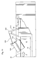
With reference to FIGS. 1-5 , there is illustrated a fluid treatment system 10. Fluid treatment system 10 comprises an open channel 12. Open channel 12 comprises a channel floor 14 and a pair of a channel side walls 16.
Disposed in open channel 10 is a bulkhead 18 having an opening 20. Surrounding opening 20 is a seal element 22. A module removal device 24 is disposed on top of bulkhead 18. An electrical control panel 26 is disposed to one side of open channel 10. A series of grates 28 are disposed across open channel 10 near the top of channel side walls 16.
A pair of radiation source modules 100 are disposed in open channel 10 on either side of bulkhead 18. The nature of radiation source modules 100 will be described in more detail below. As illustrated, upstream radiation source module 100 is partially withdrawn from its so-called “in use” position in open channel 10 whereas downstream radiation source module 100 is in a so-called “in use” position with respect to bulkhead 18 and open channel 12.
In use, a flow of fluid, typically gravity fed, enters open channel 12 and flows in the direction of arrows A resulting in a fluid level 30.
With particular reference to FIG. 2 , it will be seen that upstream radiation source module 100 is shown in a so-called “in use” position whereas downstream radiation source module 100 shown in FIG. 1 has not been shown for clarity purposes only.
As illustrated, radiation source module 100 comprises a housing 105. Housing 105 comprises a pair of module sidewalls 110,115 and a module floor 120 interconnecting module sidewalls 110,115. Housing 105 further comprises a fluid inlet 125 and a fluid outlet 130.
It will be appreciated that the combination of module sidewalls 110,115 and module floor 120 combine to confine fluid entering housing 105 to define a fluid treatment zone. Disposed in this fluid treatment zone are a series of radiation source assemblies 135. It can be seen that radiation source assemblies 135 have a longitudinal access which is disposed substantially transverse to the direction of fluid flow through open channel 12 of fluid treatment system 10.
A cleaning system 140 is coupled to radiation source assemblies 135 and is movable from a retracted position to an extended position to remove undesirable material from the exterior of radiation source assemblies 135.
With particular reference to FIGS. 7 to 9 , it can be seen that module sidewall 110 of housing 105 is removable to allow access to radiation source assemblies 135 and cleaning system 140. Module sidewall 115 and floor surface 120, is similarly removable but these are not shown for clarity purposes.
Disposed at the top of housing 105 are a pair of pivot elements 145. Pivot elements 145 are connected to a hydraulic cylinder 150 which is connected to module removal device 24.
Disposed around the periphery of fluid outlet 130 is a seal element 155 shown in FIG. 7 . Seal element 155 is positioned and dimensioned to cooperate with seal element 22 on bulkhead 18 to provide a substantial fluid tight seal between housing 105 and bulkhead 18.
Although the interior surfaces of sidewalls 110,115 are shown as being smooth, it is possible to modify the interior surface of these sidewalls to adopt one more fluid deflector elements and/or receptacles, for example, as described in Ma.
With continued reference to FIG. 2 , it can been seen that, when fluid enters housing 105 of radiation source module 100, a lower fluid level 30 a is assumed. It will also be seen that in the illustrated embodiment, in essence, housing 105 of radiation source module 100 acts as a small open channel fluid treatment system in that fluid level 30 a is unconstrained by any physical structure of radiation source module 100.
With reference to FIG. 4 , when it is desired to extract radiation source module 100 from open channel 12, hydraulic cylinder 150 shown in FIGS. 2 and 3 (not shown in FIG. 4 for clarity) is extended which has the effect of pivoting radiation source module 100 out of open channel 12. In FIG. 4 , again for clarity, downstream radiation source module 100 shown in FIG. 1 has not been illustrated. See also FIG. 5 which shows the same view as FIG. 4 except in FIG. 5 , sidewall 110 of housing 105 of radiation source module 100 is shown in place.
With reference to FIGS. 10-11 , there is illustrated a modification to radiation source module 100 illustrated in FIGS. 1-9 . Specifically, in FIG. 10 , radiation source module 100 has been modified to rotate out of open channel 10 using a winch 200 (or similar element) and cable 205 disposed on a winch module 210. All other aspects of fluid radiation system 10 and radiation source module 100 are similar to those discussed above.
With reference to FIG. 12 , there is shown an illustration of servicing of one or more radiation source assemblies 135 while radiation source module is maintained in position in open channel 12. In other words, it should be clear that extraction of entire radiation source module 100 from open channel 12 is not required to service radiation source assemblies 135.
With reference to FIGS. 13-15 , there is shown a modification of fluid treatment system 10 illustrative in FIG. 1 . Specifically, bulkhead 18 in fluid treatment system 10 in FIG. 1 has been modified to include a prefabricated bulkhead U-shaped channel element 18 a which is disposed in a channel to form element 18 b attached to channel side walls 16 and channel floor 14. A bulkhead sub-unit element 18 c is disposed in prefabricated bulkhead U-shaped channel element 18 a.
In some installations, the use of such a prefabricated bulkhead system shown in FIGS. 13-15 may be more convenient and/or less costly than casting bulkhead element 18 shown in FIG. 1 . The details of fluid treatment system 10 and radiation source module 100 are otherwise similar to those discussed above.
With reference to FIGS. 17-21 , there is illustrated a modification to fluid treatment system 100 illustrated in FIG. 1 . Specifically, in FIGS. 17-21 , the module removal device operates on the basis of linear translation instead of rotation. Thus, radiation source modules 100 are lifted in a relatively straight manner from open channel 12.
As shown, there is provided a module translation device 300 at the top of open channel 12. Module translation device 300 is movable along open channel 12 to move radiation source modules that are disposed upstream and downstream of bulkhead 18. Disposed in open channel 12 is a bulkhead guiderail 310. Module translation device 300 further comprises a winch 305 (or similar device) and a cable 308 for connection to radiation source module 100.
With particular reference to FIGS. 18-19 , the shape of bulkhead 18 and housing 105 of radiation source module 100 have been modified to facilitate translation type movement of radiation source module 100 during extraction or installation thereof. In addition, radiation source module 100 has been modified to provide a module lifting eyelet 180 on top of housing 105. Radiation source module 100 has been further modified to include a roller 190 that is disposed within bulkhead guiderail 310.
When it is desired to extract radiation source module 100 from open channel 12, a hook 309 at the end of cable 308 is engaged with eyelet portion 180 on radiation source module 100. Next, winch 305 is actuated to retract cable 308 thereby lifting the radiation source module 100 out of open channel 12. By providing roller 190 in bulkhead guiderail 310, inadvertent movement of radiation source module 100 during extraction can be obviated or mitigated. Extracted radiation source module 100 is shown in FIGS. 20-21 .
While this invention has been described with reference to illustrative embodiments and examples, the description is not intended to be construed in a limiting sense. Thus, various modifications of the illustrative embodiments, as well as other embodiments of the invention, will be apparent to persons skilled in the art upon reference to this description. For example, while the motive element of module extraction device shown in the illustrated embodiments includes a mechanical device such as winch, it is possible to modify these embodiments so that the module extraction device is human powered It is therefore contemplated that the appended claims will cover any such modifications or embodiments.
All publications, patents and patent applications referred to herein are incorporated by reference in their entirety to the same extent as if each individual publication, patent or patent application was specifically and individually indicated to be incorporated by reference in its entirety.
Claims (25)
1. A radiation source module for use in a fluid treatment system, the radiation source module comprising:
a housing having an inlet, an outlet and a fluid treatment zone disposed between; the fluid treatment zone comprising a first wall surface and a second wall surface interconnected by a floor surface, the first wall surface, the second wall surface and the floor surface configured to receive a flow of fluid that is unconstrained at the upper surface thereof through the fluid treatment zone the upper surface of the fluid in the housing being above the inlet;
a plurality of radiation source assemblies arranged as an array in the fluid treatment zone, each radiation source assembly being: (i) secured with respect to the first wall surface and the second wall surface, and (ii) configured to have a distal portion disposed in the flow of fluid and a proximal portion disposed outside of the flow of fluid; the array comprising at least two serially arranged rows of radiation source assemblies, each row comprising a plurality of radiation source assemblies; and
a module motive coupling element connected to the housing and configured to be coupled to a module motive element to permit the radiation source module to be installed in and extracted from the fluid treatment system.
2. The radiation source module defined in claim 1 , wherein the first wall surface comprises a plurality of first fluid deflector elements projecting into the fluid treatment zone.
3. The radiation source module defined in claim 2 , wherein the plurality of first fluid deflector elements are in a spaced relationship along the first wall surface with respect to the direction of fluid flow through the fluid treatment zone.
4. The radiation source module defined in claim 1 , wherein the second wall surface comprises a plurality of second fluid deflector elements projecting into the fluid treatment zone.
5. The radiation source module defined in claim 4 , wherein the plurality of second fluid deflector elements are in a spaced relationship along the second wall surface with respect to the direction of fluid flow through the fluid treatment zone.
6. The radiation source module defined in claim 1 , wherein the housing comprises a seal element configured to contact a surface of the fluid treatment system.
7. The radiation source module defined in claim 1 , wherein the first wall surface and the second wall surface are substantially parallel to one another.
8. The radiation source module defined in claim 1 , wherein the plurality of radiation source assemblies are configured such at a longitudinal axis thereof is arranged at an oblique angle with respect to the direction of fluid flow through the flow treatment system.
9. A fluid treatment system comprising:
an open channel for receiving a flow of fluid;
at least one radiation source module comprising:
a housing having an inlet, an outlet and a fluid treatment zone disposed between; the fluid treatment zone comprising a first wall surface and a second wall surface interconnected by a floor surface, the first wall surface, the second wall surface and the floor surface configured to receive a flow of fluid that is unconstrained at the upper surface thereof through the fluid treatment zone the upper surface of the fluid in the housing being above the inlet;
a plurality of radiation source assemblies arranged as an array in the fluid treatment zone, each radiation source assembly being: (i) secured with respect to the first wall surface and the second wall surface, and (ii) configured to have a distal portion disposed in the flow of fluid and a proximal portion disposed outside of the flow of fluid; the array comprising at least two serially arranged rows of radiation source assemblies, each row comprising a plurality of radiation source assemblies; and
a module motive element connected to the housing and configured to permit to be installed in and extracted from the fluid treatment system.
10. The fluid treatment system defined in claim 9 , wherein the housing comprises a seal element configured to provide a substantially fluid tight seal between the housing a surface of the open channel.
11. The fluid treatment system defined in claim 9 , wherein a bulkhead element is disposed in the open channel, the bulkhead element having an bulkhead inlet and a bulkhead outlet, the inlet of the housing configured to be disposed in fluid communication with the bulkhead outlet.
12. The fluid treatment system defined in claim 9 , wherein a bulkhead element is disposed in the open channel, the bulkhead element having an bulkhead inlet and a bulkhead outlet, and a pair of radiation source modules are configured to be disposed in the open channel such that: (i) the outlet of the housing of a first radiation source module is configured to be disposed in fluid communication with the bulkhead inlet, and (ii) the inlet of the housing of a second radiation source module is configured to be disposed in fluid communication with the bulkhead outlet.
13. The fluid treatment system defined in claim 11 , wherein the bulkhead element comprises a bulkhead seal configured to provide a substantially fluid tight seal between the bulkhead element and a surface of the radiation source module adjacent thereto.
14. The fluid treatment system defined in claim 9 , further comprising a module motive element configured to be reversibly coupled to the module motive coupling element of the radiation source module.
15. The fluid treatment system defined in claim 14 , wherein the module motive element is configured to rotate the radiation source module with respect to the open channel.
16. The fluid treatment system defined in claim 14 , wherein the module motive element is configured to translate the radiation source module with respect to the open channel.
17. The fluid treatment system defined in claim 9 , wherein the first wall surface is removable with respect to the housing.
18. The fluid treatment system defined in claim 9 , wherein the second side wall surface is removable with respect to the housing.
19. The fluid treatment system defined in claim 9 , wherein the first wall surface comprises a plurality of first fluid deflector elements projecting into the fluid treatment zone.
20. The fluid treatment system defined in claim 19 , wherein the plurality of first fluid deflector elements are in a spaced relationship along the first wall surface with respect to the direction of fluid flow through the fluid treatment zone.
21. The fluid treatment system defined in claim 9 , wherein the second wall surface comprises a plurality of second fluid deflector elements projecting into the fluid treatment zone.
22. The fluid treatment system defined in claim 21 , wherein the plurality of second fluid deflector elements are in a spaced relationship along the second wall surface with respect to the direction of fluid flow through the fluid treatment zone.
23. The fluid treatment system defined in claim 9 , wherein the plurality of radiation source assemblies are configured such at a longitudinal axis thereof is arranged at an oblique angle with respect to the direction of fluid flow through the flow treatment system.
24. The fluid treatment system defined in claim 9 , wherein the module motive element is configured to linearly move the radiation source module with respect to the open channel.
25. A fluid treatment system comprising:
an open channel for receiving a flow of fluid;
at least one radiation source module comprising:
a housing having an inlet, an outlet and a fluid treatment zone disposed between; the fluid treatment zone comprising a first wall surface and a second wall surface interconnected by a floor surface, the first wall surface, the second wall surface and the floor surface configured to receive a flow of fluid that is unconstrained at the upper surface thereof through the fluid treatment zone the upper surface of the fluid in the housing being above the inlet;
a plurality of radiation source assemblies arranged as an array in the fluid treatment zone, each radiation source assembly being: (i) secured with respect to the first wall surface and the second wall surface, (ii) configured to have a distal portion disposed in the flow of fluid and a proximal portion disposed outside of the flow of fluid and (iii) configured such at a longitudinal axis thereof is arranged at an oblique angle with respect to the direction of fluid flow through the flow treatment system; the array comprising at least two serially arranged rows of radiation source assemblies, each row comprising a plurality of radiation source assemblies; and
a module motive element connected to the housing and configured to linearly move the radiation source module with respect to the open channel.
Priority Applications (1)
| Application Number | Priority Date | Filing Date | Title |
|---|---|---|---|
| US13/994,941 US9539351B2 (en) | 2010-12-16 | 2011-12-13 | Radiation source module and fluid treatment system |
Applications Claiming Priority (3)
| Application Number | Priority Date | Filing Date | Title |
|---|---|---|---|
| US45704810P | 2010-12-16 | 2010-12-16 | |
| US13/994,941 US9539351B2 (en) | 2010-12-16 | 2011-12-13 | Radiation source module and fluid treatment system |
| PCT/CA2011/001350 WO2012079149A1 (en) | 2010-12-16 | 2011-12-13 | Radiation source module and fluid treatment system |
Publications (2)
| Publication Number | Publication Date |
|---|---|
| US20130334438A1 US20130334438A1 (en) | 2013-12-19 |
| US9539351B2 true US9539351B2 (en) | 2017-01-10 |
Family
ID=46243908
Family Applications (1)
| Application Number | Title | Priority Date | Filing Date |
|---|---|---|---|
| US13/994,941 Active 2032-03-21 US9539351B2 (en) | 2010-12-16 | 2011-12-13 | Radiation source module and fluid treatment system |
Country Status (6)
| Country | Link |
|---|---|
| US (1) | US9539351B2 (en) |
| EP (1) | EP2651550B1 (en) |
| CN (1) | CN103298549B (en) |
| AU (1) | AU2011342261A1 (en) |
| CA (1) | CA2819065C (en) |
| WO (1) | WO2012079149A1 (en) |
Families Citing this family (3)
| Publication number | Priority date | Publication date | Assignee | Title |
|---|---|---|---|---|
| US9550006B2 (en) * | 2014-09-26 | 2017-01-24 | Mag Aerospace Industries, Llc | Systems and methods for treatment of cabin surfaces and air |
| EP3604233A1 (en) | 2018-08-02 | 2020-02-05 | Xylem Europe GmbH | Water disinfection system |
| FR3095814B1 (en) * | 2019-05-07 | 2021-06-04 | Uv Germi | Device for treating water by ultraviolet radiation in the open channel of a wastewater treatment plant |
Citations (16)
| Publication number | Priority date | Publication date | Assignee | Title |
|---|---|---|---|---|
| US4482809A (en) | 1981-11-30 | 1984-11-13 | Trojan Technologies Inc. | Ultraviolet fluid purifying device |
| US4872980A (en) | 1988-09-13 | 1989-10-10 | Trojan Technologies, Inc. | Fluid purification device |
| US5006244A (en) | 1988-09-13 | 1991-04-09 | Trojan Technologies, Inc. | Fluid purification device |
| US5208461A (en) * | 1991-10-03 | 1993-05-04 | Simon Hydro-Aerobics, Inc. | Ultra-violet wastewater disinfection system |
| US5368826A (en) * | 1992-12-04 | 1994-11-29 | Infilco Degremont, Inc. | Control apparatus for fluid disinfection modules and systems |
| US5418370A (en) | 1993-03-05 | 1995-05-23 | Trojan Technologies, Inc. | Fluid treatment system and process |
| US5504335A (en) | 1994-10-17 | 1996-04-02 | Trojan Technologies, Inc. | Fluid treatment device and method |
| US5503800A (en) * | 1994-03-10 | 1996-04-02 | Uv Systems Technology, Inc. | Ultra-violet sterilizing system for waste water |
| US5952663A (en) * | 1997-07-22 | 1999-09-14 | Infilco Degremont, Inc. | Apparatus for improving UV dosage applied to fluids in open channel UV disinfection systems |
| USRE36896E (en) | 1993-03-05 | 2000-10-03 | Trojan Technologies Inc. | Fluid treatment system and process |
| US20020113021A1 (en) * | 2000-12-15 | 2002-08-22 | Trojan Technologies Inc. | Fluid treatment system and radiation sources module for use therein |
| US6500346B1 (en) | 1999-10-01 | 2002-12-31 | Trojan Technologies, Inc. | Fluid treatment device and method for treatment of fluid |
| WO2004000735A1 (en) | 2002-06-19 | 2003-12-31 | Trojan Technologies Inc. | Fluid treatment system and radiation source module for use therein |
| US20050232825A1 (en) * | 2002-05-07 | 2005-10-20 | Ultravation, Inc. | Fluid disinfection apparatus |
| WO2008055344A1 (en) | 2006-11-06 | 2008-05-15 | Trojan Technologies | Fluid treatment system |
| CN101248511A (en) | 2005-05-20 | 2008-08-20 | 特洛伊科技有限公司 | Ultraviolet radiation lamp and source module and treatment system containing same |
Family Cites Families (4)
| Publication number | Priority date | Publication date | Assignee | Title |
|---|---|---|---|---|
| US3837800A (en) * | 1971-05-06 | 1974-09-24 | Meltzer H | Method and apparatus for purifying fluids |
| US4849115A (en) * | 1987-09-21 | 1989-07-18 | Cole Leland G | Process for oxidizing organic residues in an aqueous stream |
| US8017191B2 (en) | 2006-08-31 | 2011-09-13 | Nanoink, Inc. | Fast dip for reduced wicking in nanolithograhic ink delivery |
| US20120097187A1 (en) * | 2009-03-13 | 2012-04-26 | Trojan Technologies | Cleaning apparatus, radiation source module and fluid treatment system |
-
2011
- 2011-12-13 CN CN201180060558.3A patent/CN103298549B/en not_active Expired - Fee Related
- 2011-12-13 EP EP11848955.8A patent/EP2651550B1/en active Active
- 2011-12-13 WO PCT/CA2011/001350 patent/WO2012079149A1/en active Application Filing
- 2011-12-13 AU AU2011342261A patent/AU2011342261A1/en not_active Abandoned
- 2011-12-13 US US13/994,941 patent/US9539351B2/en active Active
- 2011-12-13 CA CA2819065A patent/CA2819065C/en active Active
Patent Citations (20)
| Publication number | Priority date | Publication date | Assignee | Title |
|---|---|---|---|---|
| US4482809A (en) | 1981-11-30 | 1984-11-13 | Trojan Technologies Inc. | Ultraviolet fluid purifying device |
| US4872980A (en) | 1988-09-13 | 1989-10-10 | Trojan Technologies, Inc. | Fluid purification device |
| US5006244A (en) | 1988-09-13 | 1991-04-09 | Trojan Technologies, Inc. | Fluid purification device |
| US5208461A (en) * | 1991-10-03 | 1993-05-04 | Simon Hydro-Aerobics, Inc. | Ultra-violet wastewater disinfection system |
| US5368826A (en) * | 1992-12-04 | 1994-11-29 | Infilco Degremont, Inc. | Control apparatus for fluid disinfection modules and systems |
| USRE36896E (en) | 1993-03-05 | 2000-10-03 | Trojan Technologies Inc. | Fluid treatment system and process |
| US5539210A (en) | 1993-03-05 | 1996-07-23 | Trojan Technologies, Inc. | Radiation sensor with means to remove fouling materials |
| US5418370A (en) | 1993-03-05 | 1995-05-23 | Trojan Technologies, Inc. | Fluid treatment system and process |
| US5503800A (en) * | 1994-03-10 | 1996-04-02 | Uv Systems Technology, Inc. | Ultra-violet sterilizing system for waste water |
| US5504335A (en) | 1994-10-17 | 1996-04-02 | Trojan Technologies, Inc. | Fluid treatment device and method |
| US5952663A (en) * | 1997-07-22 | 1999-09-14 | Infilco Degremont, Inc. | Apparatus for improving UV dosage applied to fluids in open channel UV disinfection systems |
| US6500346B1 (en) | 1999-10-01 | 2002-12-31 | Trojan Technologies, Inc. | Fluid treatment device and method for treatment of fluid |
| US20020113021A1 (en) * | 2000-12-15 | 2002-08-22 | Trojan Technologies Inc. | Fluid treatment system and radiation sources module for use therein |
| CN1481337A (en) | 2000-12-15 | 2004-03-10 | 特洛伊人技术公司 | Fluid treatment system and radiation source module for use therein |
| US20050232825A1 (en) * | 2002-05-07 | 2005-10-20 | Ultravation, Inc. | Fluid disinfection apparatus |
| WO2004000735A1 (en) | 2002-06-19 | 2003-12-31 | Trojan Technologies Inc. | Fluid treatment system and radiation source module for use therein |
| US20040069954A1 (en) * | 2002-06-19 | 2004-04-15 | Trojan Technologies Inc. | Fluid treatment system and radiation sources module for use therein |
| CN1662454A (en) | 2002-06-19 | 2005-08-31 | 特洛伊人技术公司 | Fluid treatment system and radiation source module for use therein |
| CN101248511A (en) | 2005-05-20 | 2008-08-20 | 特洛伊科技有限公司 | Ultraviolet radiation lamp and source module and treatment system containing same |
| WO2008055344A1 (en) | 2006-11-06 | 2008-05-15 | Trojan Technologies | Fluid treatment system |
Non-Patent Citations (3)
| Title |
|---|
| First Office Action for Chinese Patent Application No. 2011800605583 with a date of notification of Jun. 6, 2014. |
| International Search Report for International Application No. PCT/CA2011/001350 with a mailing date of Apr. 26, 2012. |
| Second Office Action for Chinese Patent Application No. 201180060558.3 with a date of notification of Apr. 3, 2015. |
Also Published As
| Publication number | Publication date |
|---|---|
| CA2819065C (en) | 2016-02-09 |
| CA2819065A1 (en) | 2012-06-21 |
| EP2651550A1 (en) | 2013-10-23 |
| AU2011342261A1 (en) | 2013-07-25 |
| EP2651550A4 (en) | 2017-01-18 |
| CN103298549B (en) | 2015-10-14 |
| WO2012079149A1 (en) | 2012-06-21 |
| CN103298549A (en) | 2013-09-11 |
| EP2651550B1 (en) | 2021-04-14 |
| US20130334438A1 (en) | 2013-12-19 |
Similar Documents
| Publication | Publication Date | Title |
|---|---|---|
| US7323694B2 (en) | Fluid treatment system and radiation source module for use therein | |
| US8859989B2 (en) | Fluid treatment system | |
| US20080260602A1 (en) | Fluid treatment system and radiation source module for use therein | |
| EP2097352B1 (en) | Fluid treatment system | |
| CA2660719C (en) | Fluid treatment system | |
| US9771959B2 (en) | Fluid flow modifier and fluid treatment system incorporating same | |
| US9539351B2 (en) | Radiation source module and fluid treatment system | |
| US20110006223A1 (en) | Radiation source assembly and fluid treatment system | |
| EP3081534B1 (en) | Radiation source module and fluid treatment system |
Legal Events
| Date | Code | Title | Description |
|---|---|---|---|
| AS | Assignment |
Owner name: TROJAN TECHNOLOGIES, CANADA Free format text: ASSIGNMENT OF ASSIGNORS INTEREST;ASSIGNORS:TRAUBENBERG, GEORGE;PENHALE, DOUGLAS;SIGNING DATES FROM 20130827 TO 20130828;REEL/FRAME:031126/0326 |
|
| STCF | Information on status: patent grant |
Free format text: PATENTED CASE |
|
| MAFP | Maintenance fee payment |
Free format text: PAYMENT OF MAINTENANCE FEE, 4TH YEAR, LARGE ENTITY (ORIGINAL EVENT CODE: M1551); ENTITY STATUS OF PATENT OWNER: LARGE ENTITY Year of fee payment: 4 |