EP2804167A2 - Verfahren und Systeme zur Bereitstellung von Rollbahnhaltelinieninformationen an das Flugzeugpersonal - Google Patents
Verfahren und Systeme zur Bereitstellung von Rollbahnhaltelinieninformationen an das Flugzeugpersonal Download PDFInfo
- Publication number
- EP2804167A2 EP2804167A2 EP20140162517 EP14162517A EP2804167A2 EP 2804167 A2 EP2804167 A2 EP 2804167A2 EP 20140162517 EP20140162517 EP 20140162517 EP 14162517 A EP14162517 A EP 14162517A EP 2804167 A2 EP2804167 A2 EP 2804167A2
- Authority
- EP
- European Patent Office
- Prior art keywords
- stop bar
- aircraft
- processor
- subsystem
- display
- Prior art date
- Legal status (The legal status is an assumption and is not a legal conclusion. Google has not performed a legal analysis and makes no representation as to the accuracy of the status listed.)
- Ceased
Links
Images


Classifications
-
- G—PHYSICS
- G08—SIGNALLING
- G08G—TRAFFIC CONTROL SYSTEMS
- G08G5/00—Traffic control systems for aircraft, e.g. air-traffic control [ATC]
- G08G5/06—Traffic control systems for aircraft, e.g. air-traffic control [ATC] for control when on the ground
- G08G5/065—Navigation or guidance aids, e.g. for taxiing or rolling
-
- G—PHYSICS
- G06—COMPUTING; CALCULATING OR COUNTING
- G06T—IMAGE DATA PROCESSING OR GENERATION, IN GENERAL
- G06T7/00—Image analysis
- G06T7/70—Determining position or orientation of objects or cameras
- G06T7/73—Determining position or orientation of objects or cameras using feature-based methods
-
- G—PHYSICS
- G06—COMPUTING; CALCULATING OR COUNTING
- G06V—IMAGE OR VIDEO RECOGNITION OR UNDERSTANDING
- G06V20/00—Scenes; Scene-specific elements
- G06V20/50—Context or environment of the image
- G06V20/56—Context or environment of the image exterior to a vehicle by using sensors mounted on the vehicle
-
- G—PHYSICS
- G08—SIGNALLING
- G08G—TRAFFIC CONTROL SYSTEMS
- G08G5/00—Traffic control systems for aircraft, e.g. air-traffic control [ATC]
- G08G5/0017—Arrangements for implementing traffic-related aircraft activities, e.g. arrangements for generating, displaying, acquiring or managing traffic information
- G08G5/0021—Arrangements for implementing traffic-related aircraft activities, e.g. arrangements for generating, displaying, acquiring or managing traffic information located in the aircraft
-
- G—PHYSICS
- G01—MEASURING; TESTING
- G01C—MEASURING DISTANCES, LEVELS OR BEARINGS; SURVEYING; NAVIGATION; GYROSCOPIC INSTRUMENTS; PHOTOGRAMMETRY OR VIDEOGRAMMETRY
- G01C23/00—Combined instruments indicating more than one navigational value, e.g. for aircraft; Combined measuring devices for measuring two or more variables of movement, e.g. distance, speed or acceleration
-
- G—PHYSICS
- G06—COMPUTING; CALCULATING OR COUNTING
- G06T—IMAGE DATA PROCESSING OR GENERATION, IN GENERAL
- G06T2207/00—Indexing scheme for image analysis or image enhancement
- G06T2207/10—Image acquisition modality
- G06T2207/10048—Infrared image
-
- G—PHYSICS
- G06—COMPUTING; CALCULATING OR COUNTING
- G06T—IMAGE DATA PROCESSING OR GENERATION, IN GENERAL
- G06T2207/00—Indexing scheme for image analysis or image enhancement
- G06T2207/30—Subject of image; Context of image processing
- G06T2207/30248—Vehicle exterior or interior
- G06T2207/30252—Vehicle exterior; Vicinity of vehicle
- G06T2207/30256—Lane; Road marking
-
- G—PHYSICS
- G08—SIGNALLING
- G08G—TRAFFIC CONTROL SYSTEMS
- G08G5/00—Traffic control systems for aircraft, e.g. air-traffic control [ATC]
- G08G5/0017—Arrangements for implementing traffic-related aircraft activities, e.g. arrangements for generating, displaying, acquiring or managing traffic information
- G08G5/0026—Arrangements for implementing traffic-related aircraft activities, e.g. arrangements for generating, displaying, acquiring or managing traffic information located on the ground
Definitions
- the present invention generally relates to aviation, and more particularly relates to systems and methods for providing taxiway stop bar information to an aircrew.
- Modern flight deck displays for aircraft provide a considerable amount of information, such as vehicle position, speed, altitude, attitude, navigation, target, and terrain information.
- Most modern displays additionally display a flight plan from different views, either a lateral view, a vertical view, or a perspective view, which can be displayed individually or simultaneously on the same display.
- Stop bar detection solutions known in the prior art primarily include ground-based solutions such as induction loops, microwave sensors, or light gates, etc. These solutions are typically presented at complex airports with dense traffic and that have a good ground infrastructure.
- Other solutions known in the prior art include onboard solutions that are based on navigation databases with stored stop bar positions and/or datalinks from Air Traffic Control (ATC) that provides the current status of stop bars.
- ATC Air Traffic Control
- the disadvantage of these onboard solutions is the requirement for periodical updating of the database and necessary datalinks and/or radio communication between aircrew and air traffic control services.
- a system for displaying stop bar information to an aircrew member of an aircraft includes a display subsystem configured to display visual information to the aircrew member of the aircraft, a position detecting subsystem that is configured to detect a current location of the aircraft with respect to a ground surface and to generate a first signal indicative of the current location of the aircraft, a light detection subsystem that is configured to detect a light signature emitted from a stop bar, and a processor operatively coupled with the display subsystem, the position detecting subsystem, the light detection subsystem.
- the processor is configured to receive the first signal from the position detecting subsystem, to receive the second signal from the light detection subsystem, and to generate information regarding the position of a detected stop bar.
- the processor is further configured to command the display subsystem to display a graphic depiction of the detected stop bar on the display subsystem.
- a method for displaying stop bar information to an aircrew member of an aircraft includes the steps of capturing a light signature emitted from an area surrounding the aircraft, processing the captured light signature to detect a lighted stop bar, and providing information to the aircrew member regarding the detection of the lighted stop bar.
- Skilled artisans may implement the described functionality in varying ways for each particular application, but such implementation decisions should not be interpreted as causing a departure from the scope of the present invention.
- an embodiment of a system or a component may employ various integrated circuit components, e.g., memory elements, digital signal processing elements, logic elements, look-up tables, or the like, which may carry out a variety of functions under the control of one or more microprocessors or other control devices.
- integrated circuit components e.g., memory elements, digital signal processing elements, logic elements, look-up tables, or the like, which may carry out a variety of functions under the control of one or more microprocessors or other control devices.
- DSP digital signal processor
- ASIC application specific integrated circuit
- FPGA field programmable gate array
- a general-purpose processor may be a microprocessor, but in the alternative, the processor may be any conventional processor, controller, microcontroller, or state machine.
- a processor may also be implemented as a combination of computing devices, e.g., a combination of a DSP and a microprocessor, a plurality of microprocessors, one or more microprocessors in conjunction with a DSP core, or any other such configuration including but not limited to a general purpose graphics processing unit (GPGPU).
- GPGPU general purpose graphics processing unit
- a software module may reside in RAM memory, flash memory, ROM memory, EPROM memory, EEPROM memory, registers, hard disk, a removable disk, a CD-ROM, or any other form of storage medium known in the art.
- An exemplary storage medium is coupled to the processor such the processor can read information from, and write information to, the storage medium.
- the storage medium may be integral to the processor.
- the processor and the storage medium may reside in an ASIC.
- the ASIC may reside in a user terminal.
- FIG. 1 is a simplified functional block diagram illustrating a system 10 for displaying images to a pilot of an aircraft during operation of the aircraft, including for example during taxiing procedures on the grounds of an airport.
- System 10 includes multiple components each of which may be configured for mounting to aircraft.
- system 10 may be a self-contained system such that each of the components described below are contained in a single housing and are dedicated exclusively to serving the functions of system 10, while in other embodiments, the various components described below may be standalone components or they maybe components that are used as part of other systems and which are configured to be used as a shared resource between such other systems and system 10.
- system 10 includes an enhanced vision system 12 (EVS), a Global Positioning System and avionics sensors 14, a synthetic vision system 16 (SVS), a display unit 20, a display screen 22, and a processor 24.
- EVS enhanced vision system
- SVS synthetic vision system
- display unit 20 a display screen 22
- processor 24 a processor
- EVS 12 includes one or more sensors adapted for mounting to an aircraft and configured to detect a light signature originating from outside the aircraft, including for example the light signature emitted from a stop bar located on the ground on the surface area of an airport.
- the sensor may include a visible low light television camera, an infrared (IR) camera, and millimeter wave (MMW) camera or any other light sensing device capable of detecting light either within, or outside of the visible spectrum.
- the sensor is an infrared camera capable of detecting an infrared light signature.
- the light signature may include any light that is projected from, or that is reflected off of any terrain or object outside of the aircraft, including for example a stop bar as noted above.
- the light signature includes, but is not limited to, signature components from lights that are positioned adjacent to a taxiway and which are pointed to facilitate taxing operations in the surface area of an airport, such as stop bars.
- EVS 12 is configured to generate a first signal 26 and to provide first signal 26 to processor 24.
- First signal 26 is an electronic signal that includes information corresponding to the light signature detected by EVS 12. For example, if the detected light signature includes components of a stop bar adjacent to the taxiway, first signal 26 would enable processor 24 to render an indication of the stop bar, which may be a visual indication, audio indication, or any other form of indication capable of being received by an aircrew.
- EVS 12 may include a dedicated processor, a microprocessor, circuitry, or some other processing component that is configured to receive input from the one or more light detecting sensors and to generate first signal 26 using such inputs.
- EVS 12 may not include a dedicated processor, microprocessor, circuitry or other processing component, in which case the first signal 26 would comprise unprocessed inputs from the light detecting sensors of EVS 12 for processing by processor(s) 24.
- SVS 16 is an optional component of the system 10 that may or may not be included in a given embodiment. Wherein included, SVS 16 is configured to generate a two- or three-dimensional image of the topographical environment around the aircraft and generate a third signal 30 carrying SVS Image and to provide the third signal 30 to processor 24.
- SVS 16 may include a data storage device (not shown) containing a data base with data relating to the topography, which may represent either or both landscape and/or man-made structures located along the aircraft's path.
- the data base may include taxiways, runways, holding areas, and other features as may be found in the ground area of an airport.
- the data storage device may contain such data for an entire geographical region such as a state, a country or continent.
- SVS 16 may also access or include a position determining unit that is configured to determine the position of the aircraft with respect to the surface of the earth. Such a position determining unit may include, but is not limited to, a GPS system, an inertial navigation system, and the like.
- SVS 16 may be configured to receive direction, ground speed, and other avionics inputs relating to the aircraft's movement along the ground. In alternative embodiments, SVS 16 may receive the GPS and avionics inputs from the aircraft's GPS and avionics sensors 14.
- SVS 16 may include a dedicated processor, microprocessor, or other circuitry that is configured to take the information pertaining to the position and heading of the aircraft and to utilize the information available in the database to generate a third signal 30 that may be utilized by processor 24 to render a two- or three-dimensional image of the topographical environment through which the aircraft is traveling.
- SVS 16 may not include a dedicated processor, microprocessor or other circuitry.
- third signal 30 would contain the unprocessed sensor information and location data which could then be utilized by processor 24 to render the three dimensional image of the topographical environment. In either event, SVS 16 is configured to provide third signal 30 to processor 24.
- Display unit 20 may be any type of display device that generates visual output using any one of a number of different technologies.
- display unit 20 may be a Cathode Ray Tube (CRT) display device, a flat panel display device, a Liquid Crystal Display (LCD) device, a plasma display device, an electro-luminescent display device, a Light Emitting Diode (LED) display device, a holographic display device, a Head Up Display (HUD), a Micro Mirror Device (MMD) display device, a near-to-eye display or the like.
- CTR Cathode Ray Tube
- LCD Liquid Crystal Display
- LCD Liquid Crystal Display
- plasma display device an electro-luminescent display device
- LED Light Emitting Diode
- HUD Head Up Display
- MMD Micro Mirror Device
- display unit 20 includes a display screen 22 that is operatively connected to display unit 20.
- Display screen 22 is configured to be controlled by display unit 20 and may be used to display any type of image including, but not limited to, graphics and text.
- display unit 20 may include multiple display screens 22 and system 10 may include multiple display units 20.
- other units may be included that are able to provide information to the aircrew, including audio generating units (such as speakers), light generating units (such as flashing indicators), and the like.
- audio generating units such as speakers
- light generating units such as flashing indicators
- the manner by which information is provided to the aircrew, particularly stop bar information in accordance with the present disclosure, should not be understood as limited to any particular type of display or any particular type of information providing (or indication) device.
- Processor 24 may be any type of computer, computer system, microprocessor, collection of logic devices, or any other analog or digital circuitry that is configured to calculate, and/or to perform algorithms, and/or to execute software applications, and/or to execute sub-routines, and/or to be loaded with and to execute any type of computer program.
- Processor 24 may comprise a single processor or a plurality of processors acting in concert.
- processor 24 may be dedicated for use exclusively with system 10 while in other embodiments processor 24 may be shared with other systems on board the aircraft.
- processor 24 may be integrated into any of the other components of system 10.
- processor 24 may be a component of SVS 16 or of EVS 12.
- Processor 24 is communicatively coupled to EVS 12, GPS/avionics sensors 14, and SVS 16, and is operatively coupled to display unit 20. Such communicative and operative connections may be effected through the use of any suitable means of transmission, including both wired and wireless connections.
- each component may be physically connected to processor 24 via a coaxial cable or via any other type of wired connection effective to convey electronic signals.
- each component may be communicatively connected to processor 24 across a bus or other similar communication corridor.
- suitable wireless connections include, but are not limited to, a Bluetooth connection, a Wi-Fi connection, an infrared connection or the like.
- processor 24 Being communicatively and/or operatively coupled with EVS 12, GPS/avionics sensors 14, SVS 16, and display unit 20, provides processor 24 with a pathway for the receipt and transmission of signals, commands, instructions, and interrogations to and from each of the other components.
- Processor 24 is configured (i.e., loaded with and being capable of executing suitable computer code, software and/or applications) to interact with and to coordinate with each of the other components of system 10 for the purpose of providing stop bar information to the aircrew operating the aircraft on which system 10 is provided.
- processor 24 is configured to receive third signal 30 from EVS 12 and to send a command to display unit 20 instructing display unit 20 to display a corresponding image on a display screen 22 indicative of the presence of the stop bar.
- the image may merely be an image of the stop bar, or the image may be an enhanced image including one or more visual cues to draw the aircrew's attention to the stop bar.
- Other audio/visual information/indicators may be provided accompanying the image.
- Processor 24 may also be configured to receive a second signal 28 from the aircraft's GPS/Avionics system 14, to further aide in the detection of lighted stop bars.
- an image from SVS 16 may accompany the image from EVS 12 on the display screen 22 (for example, one may be overlaid on the other).
- EVS 12 is provided as an infrared (IR) camera
- IR cameras are suitable for capturing real-time scenery ahead of aircraft not only in low visibility conditions but also in normal weather conditions.
- the IR camera may be accompanied with an image processing unit that is capable of detecting the signature of a stop bar on the ground of an airport and preparing output image for display unit 20.
- image processing unit that could be used with embodiments of the present disclosure is the SmartView® system developed by Honeywell International Inc. of Morristown, NJ.
- a database may be provided that stores data regarding all stop bars at various airports. The data includes stop bar position and labels if it is available. The label is in the same format as the identification on the airport surface. The database improves the performance of the detection algorithms employed by the image processing unit.
- the system confirms the estimated position of stop bar through computer vision detection, utilizing the image processing unit.
- An image detection algorithm focuses on searching for the horizontal line formed by stop bar lighting system, when activated.
- the algorithm looks for the brightest spots in the received image and separates them from background. This is achieved by adaptive thresholding and morphological opening functions to remove noise and unimportant parts of image such a taxiway texture.
- the algorithm uses database information (if provided) for an estimation of stop bar location in image.
- the map database is electronically associated with the IR image based on GPS location, heading, and IR sensor properties such as IR sensor orientation, sensor mounting, resolution, view field, and zoom of camera. Further, information regarding the position and orientation of stop bar is associated with the data, which marks estimation position of lights in IR image.
- the algorithm can still search for stop bar at locations given by ICAO standards, for example before intersections between taxiways and runways with proper distance from runway edge and proper slope to the taxiway edge.
- the algorithm searches for lines formed by lights with similar properties as expected according to the database information. Factors that the algorithm takes into account can include, but are not limited to: location in the IR image, slope of the line of lights, and length of the line of light.
- the algorithm can further take other features into account as well. If similar lines with such features are detected, an average line that represents all of them can be computed. Special considerations are given to extended stop bar lights, which are in detected in the IR Image slightly above ground, and corrections to the line can be performed on that basis. In the case that the stop bar pavement lights are missing, the algorithm makes horizontal correction according to the ICAO standard regarding enhanced lights placement and properties.
- the output from this step is the detected location of stop bar in the IR image.
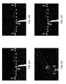
- FIGS. 2a through 2d serve to illustrate an implementation of the described algorithm.
- FIG. 2a shows an image obtained from an IR sensor with various lights clearly visible. For clarity, the stop bar lights marked as a "star" symbol. Number [1] depicts extended stop bar lights as shown in FIG. 3 and number [2] depicts pavement stop bar lights as shown in FIG. 4 . Other lights belong to the taxiway lightning system.
- FIG. 2b depicts the enhanced IR image with noise and non-critical features removed.
- FIG. 2c depicts database information about taxiways and runways. Further, FIG. 2d depicts database information super-imposed over enhanced IR image. In this manner, the system is able to generate and receive information regarding detected active stop bars, such information including position and optionally label information obtained from the database.
- the information may be displayed to the aircrew in a variety of manners, as shown in FIGS. 6 and 7.
- the information may be provided on the primary flight display associated with the aforementioned SmartView® system or other synthetic depiction image (SVS 16, for example, as shown at FIG. 6 ), 3D airport moving map and/or airport moving map on Enhanced Navigation display (ENAV, for example, as shown at FIG. 7), or any other system that is able to depict active stop bar with respect to position of the aircraft.
- the depiction can also include label of stop bar with regard to the scale of displayed image on the appropriate flight display.
- the system may further be configured to determine a motional vector of the aircraft based on current braking abilities and/or a defined fix time interval prediction. This aircraft motional vector presents area inside which the aircraft is not able to stop. In situations where the motional vector crosses the position of detected stop bars, the system generates an appropriate caution alert
- the caution can be announced by visual and/or aural means and can be designed with respect to regulations regarding cockpit design.
- the caution alert can be changed to a warning alert when an aircraft position passes over the position of detected light (i.e., when the aircraft violates a taxiway segment restricted for other traffic).
- the warning can be also announced by visual and/or aural means and can be designed with respect to regulations regarding cockpit design.
- FIG. 5 illustrates an exemplary process diagram in accordance with the above-described algorithm.
- the system captures an IR image from an area surrounding the aircraft.
- the system (optionally) obtains data from a database or other source regarding the position and configuration of stop bars at an airport.
- the information received in steps 501 and 502 is processed at step 503, using the algorithm, to detect a lighted (active) stop bar.
- the system may further be configured to calculate the motional vector of the aircraft at step 504.
- the stop bar detection information (and optionally the aircraft motional vector) is processed to provide information to the crew at steps 505 and 506 regarding the detection of the stop bar.
- a caution alert may be issued at step 507 and/or a warning alert may be issued at step 508.
- stop bar detection systems and methods disclosed herein provide a variety of benefits over systems previously known in the art.
- the system is essentially a substitution of the pilot's eyesight by the system recognizing visual cues (stop bars) determining holding points during taxiing and gives better performance than pilot's eyesight in low visibility condition.
- the solution does not need any additional equipment on the airport surface, nor does it require additional equipment on the aircraft, as many aircraft are already equipped with infrared cameras used for other purposes.
- the status of the stop bars ahead can be determined by the system.
- the database with stored stop bar positions can provide an expected position of an appropriate line for detection algorithms to thereby improve the algorithms performance.
- the system is able to generate additional caution provided when the pilot controls the aircraft in the way which would result into violation of the active taxiway segment. This caution is generated based on distance to active stop bars, current ground speed, and current braking capability.
- the system is able to generate additional warning announced when the aircraft overruns the active stop bars thereby contravenes a command provided by ATC.
- the presently described system provides an additional benefit in that the active stop bars ahead of an aircraft can be presented on either two-dimensional or three-dimensional (synthetic) displays such as an airport moving map.
- the caution about a possible overrun of the active stop bar can be depicted for the pilot on the Primary Flight Display.
- the warning about an overrun of the active stop bar can be also depicted for pilot on the Primary Flight Display.
Applications Claiming Priority (1)
| Application Number | Priority Date | Filing Date | Title |
|---|---|---|---|
| US13/860,699 US9734729B2 (en) | 2013-04-11 | 2013-04-11 | Methods and systems for providing taxiway stop bar information to an aircrew |
Publications (2)
| Publication Number | Publication Date |
|---|---|
| EP2804167A2 true EP2804167A2 (de) | 2014-11-19 |
| EP2804167A3 EP2804167A3 (de) | 2015-03-11 |
Family
ID=50440488
Family Applications (1)
| Application Number | Title | Priority Date | Filing Date |
|---|---|---|---|
| EP20140162517 Ceased EP2804167A3 (de) | 2013-04-11 | 2014-03-28 | Verfahren und Systeme zur Bereitstellung von Rollbahnhaltelinieninformationen an das Flugzeugpersonal |
Country Status (2)
| Country | Link |
|---|---|
| US (1) | US9734729B2 (de) |
| EP (1) | EP2804167A3 (de) |
Cited By (1)
| Publication number | Priority date | Publication date | Assignee | Title |
|---|---|---|---|---|
| EP3364396A3 (de) * | 2017-02-15 | 2019-01-02 | Honeywell International Inc. | Anzeigesysteme und verfahren zur verhinderung von einbrüchen auf der laufbahn |
Families Citing this family (7)
| Publication number | Priority date | Publication date | Assignee | Title |
|---|---|---|---|---|
| US9762895B1 (en) * | 2014-03-11 | 2017-09-12 | Rockwell Collins, Inc. | Dual simultaneous image presentation for a three-dimensional aviation display |
| US11586208B2 (en) * | 2014-10-24 | 2023-02-21 | Clearpath Robotics Inc. | Systems and methods for executing a task with an unmanned vehicle |
| US10127821B2 (en) | 2015-06-24 | 2018-11-13 | Honeywell International Inc. | Aircraft systems and methods to improve airport traffic management |
| US10354163B2 (en) * | 2017-06-19 | 2019-07-16 | Honeywell International Inc. | Enhanced computer vision using object location information |
| FR3071092B1 (fr) * | 2017-09-13 | 2022-07-22 | Airbus | Procede et systeme d'aide a la navigation d'un avion sur un aeroport |
| GB2576880B (en) * | 2018-09-04 | 2021-05-12 | Ge Aviat Systems Ltd | Method and system for avionics component maintenance |
| EP3715901A1 (de) * | 2019-03-29 | 2020-09-30 | Robin Radar Facilities BV | Erkennung und klassifizierung von unbemannten luftfahrzeugen |
Family Cites Families (25)
| Publication number | Priority date | Publication date | Assignee | Title |
|---|---|---|---|---|
| DE3377391D1 (en) | 1983-12-20 | 1988-08-18 | Huber Signalbau Muenchen | Taxiway safety device for airports |
| JPH04328099A (ja) | 1991-04-30 | 1992-11-17 | Toshiba Corp | 航空機検知センサ |
| US5485151A (en) | 1993-05-06 | 1996-01-16 | Adb-Alnaco, Inc. | Airfield lighting system |
| DE19635679A1 (de) | 1996-09-03 | 1998-03-05 | Siemens Ag | Mensch-Maschine-Schnittstelle (Man-Machine-Interface, MMI) für Flughäfen und Luftverkehrszwecke |
| DE19752559B4 (de) | 1997-11-27 | 2004-01-22 | Honeywell Ag | Verfahren zur Führung von Flugzeugen auf Rollwegen |
| US6232602B1 (en) | 1999-03-05 | 2001-05-15 | Flir Systems, Inc. | Enhanced vision system sensitive to infrared radiation |
| US6606563B2 (en) | 2001-03-06 | 2003-08-12 | Honeywell International Inc. | Incursion alerting system |
| US20030160708A1 (en) | 2002-02-27 | 2003-08-28 | Knoop Alan Richard | Airport ground control system |
| JP4328099B2 (ja) | 2003-01-29 | 2009-09-09 | オリンパス株式会社 | 結像光学系及びそれを用いた撮像装置 |
| US7414545B2 (en) * | 2003-12-18 | 2008-08-19 | George Vickas | Incursion collision avoidance system for vehicle traffic control |
| US7196329B1 (en) | 2004-06-17 | 2007-03-27 | Rockwell Collins, Inc. | Head-down enhanced vision system |
| US7382288B1 (en) | 2004-06-30 | 2008-06-03 | Rockwell Collins, Inc. | Display of airport signs on head-up display |
| FR2891646B1 (fr) * | 2005-09-30 | 2016-07-01 | Thales Sa | Procede et dispositif embarque d'aide au roulage dans un aeroport. |
| DE102006007644B4 (de) | 2006-02-18 | 2008-01-31 | Heinz Wipf | Verfahren und System zur Eindringverhinderung eines beweglichen Objekts in einen Abschnitt eines Verkehrsweges |
| US7567187B2 (en) * | 2006-08-11 | 2009-07-28 | Honeywell International Inc. | Taxiway awareness and advisory system |
| US7908079B1 (en) | 2006-09-18 | 2011-03-15 | The United States Of America As Represented By The Administrator Of The National Aeronautics And Space Administration | Portable runway intersection display and monitoring system |
| FR2910681B1 (fr) | 2006-12-20 | 2009-03-06 | Thales Sa | Systeme d'affichage selectif d'informations de trafic d'aeroport |
| FR2917223B1 (fr) | 2007-06-08 | 2009-07-17 | Thales Sa | Systeme d'aide au guidage d'un aeronef sur un aeroport |
| FR2922072B1 (fr) | 2007-10-03 | 2011-04-29 | Latecoere | Procede et systeme d'aide au roulage d'un aeronef |
| AU2008309617A1 (en) | 2007-10-09 | 2009-04-16 | Adb Bvba | Device for detecting a vehicle on an airport runway |
| EP2110798A1 (de) * | 2008-04-16 | 2009-10-21 | Siemens Aktiengesellschaft | Verfahren zur Überwachung eines Verkehrswegs für ein Verkehrsmittel einer vorbestimmten Art |
| US8903655B2 (en) * | 2009-11-30 | 2014-12-02 | Honeywell International Inc. | Method and system for displaying emphasized aircraft taxi landmarks |
| FR2959052B1 (fr) | 2010-04-16 | 2012-12-28 | Thales Sa | Dispositif d'assistance embarque au suivi d'une route aeroportuaire par un aeronef |
| WO2013020070A2 (en) | 2011-08-03 | 2013-02-07 | Stc, Inc. | Light rail vehicle monitoring and stop bar overrun system |
| US8880328B2 (en) * | 2012-11-02 | 2014-11-04 | Ge Aviation Systems Llc | Method of optically locating an aircraft relative to an airport |
-
2013
- 2013-04-11 US US13/860,699 patent/US9734729B2/en active Active
-
2014
- 2014-03-28 EP EP20140162517 patent/EP2804167A3/de not_active Ceased
Non-Patent Citations (1)
| Title |
|---|
| None |
Cited By (2)
| Publication number | Priority date | Publication date | Assignee | Title |
|---|---|---|---|---|
| EP3364396A3 (de) * | 2017-02-15 | 2019-01-02 | Honeywell International Inc. | Anzeigesysteme und verfahren zur verhinderung von einbrüchen auf der laufbahn |
| US10446039B2 (en) | 2017-02-15 | 2019-10-15 | Honeywell International Inc. | Display systems and methods for preventing runway incursions |
Also Published As
| Publication number | Publication date |
|---|---|
| US9734729B2 (en) | 2017-08-15 |
| US20140309915A1 (en) | 2014-10-16 |
| EP2804167A3 (de) | 2015-03-11 |
Similar Documents
| Publication | Publication Date | Title |
|---|---|---|
| US9734729B2 (en) | Methods and systems for providing taxiway stop bar information to an aircrew | |
| EP2835795B1 (de) | System und Verfahren zum Hervorheben eines gefahrenfreien, das Flugzeug umschließenden Bereichs | |
| EP2856455B1 (de) | Systeme und verfahren für erhöhtes bewusstsein der nähe eines hindernisses bei rollfeldoperationen | |
| US9478140B2 (en) | System and method for displaying traffic and associated alerts on a three-dimensional airport moving map display | |
| EP2610590B1 (de) | System und Verfahren zur Auswahl von anzuzeigenden Bildern | |
| US9959774B2 (en) | Systems and methods for displaying obstacle-avoidance information during surface operations | |
| EP3199918B1 (de) | Cockpitanzeigesysteme und verfahren zur erzeugung von cockpitanzeigen mit indikatoren für verbesserte flugsicht | |
| US10140876B2 (en) | Systems and methods for enhanced awareness of obstacle proximity during taxi operations | |
| US8880328B2 (en) | Method of optically locating an aircraft relative to an airport | |
| EP2947638A1 (de) | Flughafenflächekollisionszonenanzeige für eines flugzeug | |
| EP2618322B1 (de) | System und Verfahren zum Erkennen und Anzeigen von Flugzeugankunftslichtern | |
| EP2492890A2 (de) | Flugzeugsystem und Verfahren zur Anzeige visueller Segmentinformationen | |
| US8810435B2 (en) | Apparatus and method for displaying a helicopter approach to an airport landing pad | |
| US8462205B2 (en) | Landing Aid Device and Method | |
| US20130321193A1 (en) | Systems and methods for filtering wingtip sensor information | |
| EP2919219B1 (de) | System und Verfahren zur Identifizierung der Rollbahnposition während des Abflugs auf einer Rollbahneinmündung | |
| EP2892041A1 (de) | Verbessertes Bewusstsein von Hindernisnähe | |
| EP2891900A1 (de) | Verbessertes Bewusstsein von Hindernisnähe | |
| EP3198582A1 (de) | Verfahren und systeme zur kollisionsvermeidung unter verwendung einer visuellen indikation des tragflächenspitzenwegs |
Legal Events
| Date | Code | Title | Description |
|---|---|---|---|
| PUAI | Public reference made under article 153(3) epc to a published international application that has entered the european phase |
Free format text: ORIGINAL CODE: 0009012 |
|
| 17P | Request for examination filed |
Effective date: 20140328 |
|
| AK | Designated contracting states |
Kind code of ref document: A2 Designated state(s): AL AT BE BG CH CY CZ DE DK EE ES FI FR GB GR HR HU IE IS IT LI LT LU LV MC MK MT NL NO PL PT RO RS SE SI SK SM TR |
|
| AX | Request for extension of the european patent |
Extension state: BA ME |
|
| PUAL | Search report despatched |
Free format text: ORIGINAL CODE: 0009013 |
|
| AK | Designated contracting states |
Kind code of ref document: A3 Designated state(s): AL AT BE BG CH CY CZ DE DK EE ES FI FR GB GR HR HU IE IS IT LI LT LU LV MC MK MT NL NO PL PT RO RS SE SI SK SM TR |
|
| AX | Request for extension of the european patent |
Extension state: BA ME |
|
| RIC1 | Information provided on ipc code assigned before grant |
Ipc: G06T 7/00 20060101ALI20150203BHEP Ipc: G08G 5/06 20060101ALI20150203BHEP Ipc: G08G 5/00 20060101AFI20150203BHEP Ipc: G06K 9/00 20060101ALI20150203BHEP Ipc: B64D 47/08 20060101ALI20150203BHEP |
|
| 17Q | First examination report despatched |
Effective date: 20150225 |
|
| R17C | First examination report despatched (corrected) |
Effective date: 20150831 |
|
| RAP1 | Party data changed (applicant data changed or rights of an application transferred) |
Owner name: HONEYWELL INTERNATIONAL INC. |
|
| STAA | Information on the status of an ep patent application or granted ep patent |
Free format text: STATUS: THE APPLICATION HAS BEEN REFUSED |
|
| 18R | Application refused |
Effective date: 20180426 |