EP2804029A2 - Linse und Beleuchtungsvorrichtung mit der Linse - Google Patents
Linse und Beleuchtungsvorrichtung mit der Linse Download PDFInfo
- Publication number
- EP2804029A2 EP2804029A2 EP14167693.2A EP14167693A EP2804029A2 EP 2804029 A2 EP2804029 A2 EP 2804029A2 EP 14167693 A EP14167693 A EP 14167693A EP 2804029 A2 EP2804029 A2 EP 2804029A2
- Authority
- EP
- European Patent Office
- Prior art keywords
- sub
- lens
- emergent
- incident
- light
- Prior art date
- Legal status (The legal status is an assumption and is not a legal conclusion. Google has not performed a legal analysis and makes no representation as to the accuracy of the status listed.)
- Granted
Links
Images

Classifications
-
- G—PHYSICS
- G02—OPTICS
- G02B—OPTICAL ELEMENTS, SYSTEMS OR APPARATUS
- G02B19/00—Condensers, e.g. light collectors or similar non-imaging optics
- G02B19/0033—Condensers, e.g. light collectors or similar non-imaging optics characterised by the use
- G02B19/0047—Condensers, e.g. light collectors or similar non-imaging optics characterised by the use for use with a light source
- G02B19/0061—Condensers, e.g. light collectors or similar non-imaging optics characterised by the use for use with a light source the light source comprising a LED
-
- G—PHYSICS
- G02—OPTICS
- G02B—OPTICAL ELEMENTS, SYSTEMS OR APPARATUS
- G02B19/00—Condensers, e.g. light collectors or similar non-imaging optics
- G02B19/0004—Condensers, e.g. light collectors or similar non-imaging optics characterised by the optical means employed
- G02B19/0028—Condensers, e.g. light collectors or similar non-imaging optics characterised by the optical means employed refractive and reflective surfaces, e.g. non-imaging catadioptric systems
Definitions
- the present invention relates to a lens for an illuminating device.
- the present invention further relates to an illuminating device having the lens of such type.
- the present invention provides a lens for an illuminating device.
- This lens can make good secondary optical processing for light from the light source in various types of application circumstances, especially in billboard illumination, so as to provide uniform illumination to a lighted object.
- the present invention further relates to an illuminating device having the lens of such type.
- the first object of the present invention is accomplished via a lens for illuminating device.
- the lens comprises a bottom surface and an emergent surface rising from the bottom surface, the bottom surface defines a first recessed region, a surface of the first recessed region forms an incident surface, wherein the bottom surface further defines a second recessed region adjacent to the first recessed region, at least part of a surface of the second recessed region forms a total internal reflection surface, wherein part of light from a light source of the illuminating device, after incident through the incident surface and emerging through the emergent surface, is deflected to one side of an optical axis of the light source, and most of emergent light of remaining part of light, after incident through the incident surface, reflected by the total internal reflection surface and emerging through the emergent surface, is deflected to the one side of the optical axis.
- the lens according to the present invention mixes two concepts of the total internal reflection lens and the asymmetric lens, light from the light source, after passing through the lens according to the present invention
- the lens has a symmetric plane perpendicular to the bottom surface, the lens is symmetric relative to the symmetric plane, and the lens is asymmetric relative to other cross sections perpendicular to the symmetric plane and bottom surface.
- the lens is formed in such a manner that an axially symmetric lens is stretched in one direction, and the lens is configured asymmetric in a cross section perpendicular to the bottom surface and a longitudinal extending direction of the stretched lens, consequently, the light from the light source, after emerging through the lens, forms asymmetric light at both sides of the cross section, so that the light from the light source is deflected to a predetermined region, while light at both sides of the symmetric plane of the lens is symmetric such that uniform optical distribution is obtained at both sides of the symmetric plane.
- the incident surface comprises a first sub incident surface and a second sub incident surface, wherein part of light from the light source of the illuminating device, after incident through the first sub incident surface and emerging through the emergent surface, is deflected to one side of an optical axis of the light source, and most of emergent light in the remaining part of light, after incident through the second sub incident surface, reflected by the total internal reflection surface and emerging through the emergent surface, likewise is deflected to the one side of the optical axis.
- the first sub incident surface and the emergent surface are in cooperation to form an asymmetric lens part of the lens according to the present invention, while the second sub incident surface, the total internal reflection surface and the emergent surface are in cooperation to form a total internal reflection lens part of the lens according to the present invention. Therefore, the light from the light source is deflected to the predetermined region to the greatest extent so as to improve the luminous efficiency.
- the first sub incident surface and the second sub incident surface are symmetric relative to the symmetric plane, respectively, wherein, advantageously, the first sub incident surface is designed as a polynomial asphere.
- the second sub incident surface is designed as a plane.
- the second sub incident surface is inclined in a direction closing to the optical axis, thus, the second sub incident surface will not affect the demolding.
- the surface of the second recessed region includes the total internal reflection surface and a first demolding surface, wherein, viewed in the symmetric plane, the total internal reflection surface is arranged ajacent to the second incident surface.
- the total internal reflection surface is configured as a curved surface inclined in a direction away from the optical axis, wherein the curved surface is curved towards a direction of a cavity defined by the second recessed region.
- the curve profile of the total internal reflection surface completely depends upon an inclination angle of the second incident surface relative to the bottom surface.
- the total internal reflection surface and the first demolding surface are symmetric relative to the symmetric plane, respectively.
- the first demolding surface is configured as a free-form surface, wherein the free-form surface is inclined in a direction closing to the optical axis.
- a profile of the free-form surface can be arbitrary since the first demolding surface itself has no function in the optical sense.
- the sole standard of configuration of the free-form surface is that it does not interfere demolding.
- the emergent surface is configured as a polynomial asphere.
- the emergent surface comprises a first sub emergent surface, a second sub emergent surface and a third sub emergent surface, wherein the first sub emergent surface is configured to rise in a direction away from the bottom surface, the second sub emergent surface is configured to recess in a direction towards the bottom surface and the third sub emergent surface joins the bottom surface so as to form a second demolding surface.
- Configuration of profiles of curves of the sub emergent surfaces of the emergent surface, especially the first and second sub emergent surfaces are based on the first incident surface and the second incident surface.
- the third sub emergent surface actually is only a demolding surface and has no function in the optical sense.
- the first sub emergent surface is configured in such a manner that a first part of light from the first sub incident surface, after emerging through the first sub emergent surface, is deflected to the one side of the optical axis of the light source.
- the second sub emergent surface is configured in such a manner that a second part of light from the first sub incident surface, after emerging through the second sub emergent surface, is deflected to the one side of the optical axis of the light source, and most of light in light from the second incident surface, after reflected by the total internal reflection surface and emerging through the second sub emergent surface, is deflected to the one side of the optical axis of the light source.
- the first sub emergent surface, the second sub emergent surface and the third sub emergent surface are in smooth transition therebetween, wherein the third sub emergent surface is inclined in a direction closing to the optical axis, which is quite favorable for the demolding process when manufacturing the lens.
- the first sub emergent surface, the second sub emergent surface and the third sub emergent surface are symmetric relative to the symmetric plane.
- the first recessed region is configured as an accommodation cavity of the light source, and the second recessed region is configured as an assistant demolding cavity.
- the other object of the present invention is accomplished via an illuminating device, comprising a light source, wherein the illuminating device further comprises the lens of the above type.
- the light source comprises a printed circuit board and at least LED chip arranged on the printed circuit board, wherein one LED chip is arranged in the first recessed region of the lens
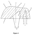
- Fig. 1 shows a cross-section view of a lens 100 according to the present invention cut off through a symmetric plane.
- the lens 100 comprises a bottom surface 1 and an emergent surface 2 rising from the bottom surface 1.
- the bottom surface 1 defines a first recessed region 3, a surface of the first recessed region 3 forms an incident surface 4. It can be seen further from the figure that the bottom surface 1 also defines a second recessed region 5 adjacent to the first recessed region 3, wherein the first recessed region 3 is configured as an accommodation cavity of a light source 6, while the second recessed region 5 is configured as an assistant demolding cavity.
- the lens 100 has a symmetric plane (a plane defined by the paper surface) perpendicular to the bottom surface 1, the lens 100 is symmetric relative to the symmetric plane, and the lens 100 is asymmetric relative to other cross sections perpendicular to the symmetric plane and bottom surface 1 (see Fig. 2 ).
- the lens 100 is formed in such a manner that an axially symmetric lens is stretched in one direction, and the lens is configured asymmetric in a cross section perpendicular to the bottom surface 1 and a longitudinal extending direction of the stretched lens 100, as shown in the figure.
- the incident surface 4 comprises a first sub incident surface 41 and a second sub incident surface 42, and the first sub incident surface 41 and the second sub incident surface 42 are symmetric relative to the symmetric plane, respectively.
- the first sub incident surface 41 is designed as a polynomial asphere
- the second sub incident surface 42 is designed as a plane
- the second sub incident surface 42 is inclined in a direction closing to an optical axis X, and the second sub incident surface 42 so configured will not affect demolding.
- the incident surface 2 is shown, and it is likewise configured as a polynomial asphere.
- the emergent surface 2 comprises a first sub emergent surface 21, a second sub emergent surface 22 and a third sub emergent surface 23, wherein the first sub emergent surface 21 is configured to rise in a direction away from the bottom surface 1, the second sub emergent surface 22 is configured to recess in a direction towards the bottom surface 1 and the third sub emergent surface 23 joins the bottom surface 1 so as to form a second demolding surface.
- first sub emergent surface 21, the second sub emergent surface 22 and the third sub emergent surface 23 are in smooth transition therebetween, wherein the third sub emergent surface 23 is inclined towards the direction of the optical axis X, and the first sub emergent surface 21, the second sub emergent surface 22 and the third sub emergent surface 23 are symmetric relative to the symmetric plane, respectively.
- Configuration of profiles of curves of the sub emergent surfaces 21, 22, 23 of the emergent surface 2, especially the first and second sub emergent surfaces 21, 22 are based on the first incident surface 41 and the second incident surface 42.
- the third sub emergent surface 23 actually is only a demolding surface and has no function in the optical sense.
- the second recessed region 5 is shown on the right side of the first recessed region 3, wherein a surface of the second recessed region 5 includes a total internal reflection surface 51 and a first demolding surface 52, wherein, viewed in the symmetric plane, the total internal reflection surface 51 is arranged ajacent to the second incident surface 42, that is to say, the total internal reflection surface 51 is arranged on the right side of the incident surface 42.
- the total internal reflection surface 51 is configured as a curved surface inclined in a direction away from the optical axis X, wherein the curved surface is curved towards a direction of a cavity defined by the second recessed region 5.
- the total internal reflection surface 51 and the first demolding surface 52 are symmetric relative to the symmetric plane, respectively, and the first demolding surface 52 is configured as a free-form surface, wherein the free-form surface is inclined in a direction closing to the optical axis X, wherein a profile of the free-form surface can be arbitrary since the first demolding surface 52 itself has no function in the optical sense.
- the sole standard of configuration of the free-form surface is that it does not interfere demolding.
- curves of the first incident surface 41, the first emergent surface 21 and the second emergent surface 22 are in coordination with each other so as to ensure that the light, after passing through the lens 100, is deflected to the left side of the lens 100 shown in the figure (see Fig. 3 ).
- the curve profile of the total internal reflection surface 51 and the curve of the second emergent surface 22 are in coordination with each other so as to ensure that the light, after passing through the lens 100, is deflected to the left side of the lens 100 shown in the figure.
- Fig. 2 shows a perspective view of the lens 100 according to the present invention viewed from a bottom direction. It can be seen visually from the figure that the lens 100 is a stretched lens with a flat bottom, wherein the first recessed region 3 and the second recessed region 5 are defined in the bottom surface, wherein the light source 6 is arranged in the first recessed region 3.
- the second recessed region 5 serves a function of providing the total internal reflection surface 51, and other parts of the second recessed region 5 are mainly assistant areas favorable for demolding.
- the light emerging through the lens 100 should be deflected towards the left side of the lens 100, therefore, part of the light from the light source 6 arranged in the first recessed region 3, after incident through the incident surface 4 and emerging through the emergent surface 2, is deflected to one side of the optical axis X (left side of the lens 100 shown in the figure) of the light source, and most of emergent light in the remaining part of light, after incident through the incident surface 4, reflected by the total internal reflection surface 51, and emerging through the emergent surface 2, is deflected to the one side of the optical axis X.
- a part of light from the light source 6 is incident through the first sub incident surface 41, wherein a first part of light from the first sub incident surface 41, after emerging through the first sub emergent surface 21, is deflected to one side of the optical axis X of the light source, a second part of light from the first sub incident surface 41, after emerging through the second sub emergent surface 21, is deflected to one side of the optical axis X of the light source, and most of light in the light from the second incident surface 42, after reflected by the total internal reflection surface 51 and emerging through the second sub emergent surface 22, is deflected to one side of the optical axis X of the light source.
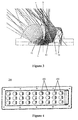
- Fig. 4 is top view of an illuminating device 200 having the lens 100 according to the present invention. It can be seen from the figure that the illuminating device 200 has a basic profile of rectangle, wherein the light source 6 of the illuminating device 200 is configured as an LED chip arranged in a housing, and a lens array having a plurality of lenses 100 in an array are arranged at opening of the housing. In the solution of the present invention, a plurality of LED chips are arranged on the printed circuit board, wherein one lens 100 is corresponding to one LED chip of the illuminating device.
- the lenses 100 are arranged regularly on the housing, that is to say, light emerging through each lens 100 is deflected to the left side of the illuminating device shown in the figure, therefore, the illuminating device having the lenses 100 of such type can uniformly light billboards with a relatively large scale.
Landscapes
- Physics & Mathematics (AREA)
- General Physics & Mathematics (AREA)
- Optics & Photonics (AREA)
- Lenses (AREA)
Applications Claiming Priority (1)
| Application Number | Priority Date | Filing Date | Title |
|---|---|---|---|
| CN201310180026.4A CN104154493B (zh) | 2013-05-15 | 2013-05-15 | 透镜和具有该透镜的照明装置 |
Publications (3)
| Publication Number | Publication Date |
|---|---|
| EP2804029A2 true EP2804029A2 (de) | 2014-11-19 |
| EP2804029A3 EP2804029A3 (de) | 2015-03-04 |
| EP2804029B1 EP2804029B1 (de) | 2018-08-08 |
Family
ID=50678090
Family Applications (1)
| Application Number | Title | Priority Date | Filing Date |
|---|---|---|---|
| EP14167693.2A Not-in-force EP2804029B1 (de) | 2013-05-15 | 2014-05-09 | Linse und Beleuchtungsvorrichtung mit der Linse |
Country Status (2)
| Country | Link |
|---|---|
| EP (1) | EP2804029B1 (de) |
| CN (1) | CN104154493B (de) |
Cited By (5)
| Publication number | Priority date | Publication date | Assignee | Title |
|---|---|---|---|---|
| US20140043809A1 (en) * | 2011-08-11 | 2014-02-13 | Hella Kgaa Hueck & Co. | Light Module for an Exterior Light |
| EP3211297A1 (de) * | 2016-02-24 | 2017-08-30 | Siteco Beleuchtungstechnik GmbH | Leuchtenmodul insbesondere für strassenleuchten |
| WO2018138406A1 (en) * | 2017-01-25 | 2018-08-02 | Ledil Oy | An optical device for modifying light distribution |
| CN109668121A (zh) * | 2017-10-12 | 2019-04-23 | 欧司朗股份有限公司 | 透镜组件及照明模块 |
| KR102152649B1 (ko) * | 2020-06-19 | 2020-09-07 | 주식회사 에이치엘옵틱스 | 확산판 지지형 렌즈 |
Family Cites Families (8)
| Publication number | Priority date | Publication date | Assignee | Title |
|---|---|---|---|---|
| CN101260987A (zh) * | 2008-04-16 | 2008-09-10 | 上海三思电子工程有限公司 | 偏光式led发光管 |
| US9255686B2 (en) * | 2009-05-29 | 2016-02-09 | Cree, Inc. | Multi-lens LED-array optic system |
| TWI422074B (zh) * | 2010-01-07 | 2014-01-01 | 首爾半導體股份有限公司 | 非球面led鏡片以及含有此鏡片的發光元件 |
| CN201836811U (zh) * | 2010-11-03 | 2011-05-18 | 四川新力光源有限公司 | 集成大功率led透镜 |
| CN202266982U (zh) * | 2011-07-25 | 2012-06-06 | 东莞市欧科光电科技有限公司 | Led光学透镜 |
| TWI463184B (zh) * | 2011-08-16 | 2014-12-01 | E Pin Optical Industry Co Ltd | 非球面發光二極體鏡片及其所構成的發光二極體組件 |
| GB2506138B (en) * | 2012-09-20 | 2014-11-19 | Cooper Technologies Co | Lens and light emitting device incorporating a lens |
| US20140192521A1 (en) * | 2013-01-10 | 2014-07-10 | Ledil Oy | Light guide element |
-
2013
- 2013-05-15 CN CN201310180026.4A patent/CN104154493B/zh active Active
-
2014
- 2014-05-09 EP EP14167693.2A patent/EP2804029B1/de not_active Not-in-force
Non-Patent Citations (1)
| Title |
|---|
| None |
Cited By (10)
| Publication number | Priority date | Publication date | Assignee | Title |
|---|---|---|---|---|
| US20140043809A1 (en) * | 2011-08-11 | 2014-02-13 | Hella Kgaa Hueck & Co. | Light Module for an Exterior Light |
| US9086192B2 (en) * | 2011-08-11 | 2015-07-21 | Hella Kgaa Hueck & Co. | Light module having a cover with a plurality of optical systems, each optical system having a plurality of optical regions and optical elements |
| EP3211297A1 (de) * | 2016-02-24 | 2017-08-30 | Siteco Beleuchtungstechnik GmbH | Leuchtenmodul insbesondere für strassenleuchten |
| EP3211297B1 (de) | 2016-02-24 | 2024-09-11 | SITECO GmbH | Leuchtenmodul insbesondere für strassenleuchten |
| WO2018138406A1 (en) * | 2017-01-25 | 2018-08-02 | Ledil Oy | An optical device for modifying light distribution |
| US10429035B2 (en) | 2017-01-25 | 2019-10-01 | Ledil Oy | Optical device for modifying light distribution |
| CN109668121A (zh) * | 2017-10-12 | 2019-04-23 | 欧司朗股份有限公司 | 透镜组件及照明模块 |
| CN109668121B (zh) * | 2017-10-12 | 2022-10-04 | 欧司朗股份有限公司 | 透镜组件及照明模块 |
| KR102152649B1 (ko) * | 2020-06-19 | 2020-09-07 | 주식회사 에이치엘옵틱스 | 확산판 지지형 렌즈 |
| WO2021256729A1 (ko) * | 2020-06-19 | 2021-12-23 | 주식회사 에이치엘옵틱스 | 확산판 지지형 렌즈 |
Also Published As
| Publication number | Publication date |
|---|---|
| EP2804029A3 (de) | 2015-03-04 |
| CN104154493B (zh) | 2019-04-09 |
| CN104154493A (zh) | 2014-11-19 |
| EP2804029B1 (de) | 2018-08-08 |
Similar Documents
| Publication | Publication Date | Title |
|---|---|---|
| EP2867714B1 (de) | Led-beleuchtungslinse | |
| US8267565B2 (en) | LED illumination device and LED illumination module for generating uniform stripped light source | |
| TWI534391B (zh) | 光源導引結構及發光裝置 | |
| CN203930195U (zh) | 用于改变光源的光分布图案的光导元件 | |
| EP2804029B1 (de) | Linse und Beleuchtungsvorrichtung mit der Linse | |
| CN103968326B (zh) | 透镜和具有该透镜的照明装置 | |
| US20140362589A1 (en) | Lens | |
| US20140321128A1 (en) | Optical lens and light source device | |
| US20150124459A1 (en) | Lens, LED Module and Illumination System Having Same | |
| US10520163B2 (en) | Light bundle control member, light emitting device, and illuminating device | |
| TWI721253B (zh) | 光學透鏡、導光罩及雙面發光裝置 | |
| JP5668920B2 (ja) | 照明装置 | |
| CN105222086B (zh) | 二次光学元件及光源模块 | |
| CN101761866B (zh) | 光学透镜及其发光二极管照明装置 | |
| CN104235758B (zh) | 透镜、具有该透镜的导光罩和使用该透镜的照明装置 | |
| EP3511613A1 (de) | Linse, lichtquellenmodul und beleuchtungsvorrichtung | |
| TW201321667A (zh) | 光源模組及發光裝置 | |
| US9354432B2 (en) | Lens with discontinuous sub-light emerging faces | |
| CN106090826A (zh) | 光学透镜和发光装置 | |
| US8684585B2 (en) | Illumination device and lens thereof | |
| CN104302973A (zh) | 用于宽横向角度分布的透镜 | |
| JP2012174445A (ja) | 導光部材及びこれを備えた発光装置 | |
| CN115144949A (zh) | 导光板及照明装置 | |
| WO2021212370A1 (zh) | 照明装置及光学模块 | |
| US9506625B2 (en) | Light source module |
Legal Events
| Date | Code | Title | Description |
|---|---|---|---|
| PUAI | Public reference made under article 153(3) epc to a published international application that has entered the european phase |
Free format text: ORIGINAL CODE: 0009012 |
|
| 17P | Request for examination filed |
Effective date: 20140509 |
|
| AK | Designated contracting states |
Kind code of ref document: A2 Designated state(s): AL AT BE BG CH CY CZ DE DK EE ES FI FR GB GR HR HU IE IS IT LI LT LU LV MC MK MT NL NO PL PT RO RS SE SI SK SM TR |
|
| AX | Request for extension of the european patent |
Extension state: BA ME |
|
| PUAL | Search report despatched |
Free format text: ORIGINAL CODE: 0009013 |
|
| RIC1 | Information provided on ipc code assigned before grant |
Ipc: G02B 3/02 20060101AFI20150120BHEP Ipc: G02B 19/00 20060101ALI20150120BHEP Ipc: F21K 99/00 20100101ALI20150120BHEP |
|
| AK | Designated contracting states |
Kind code of ref document: A3 Designated state(s): AL AT BE BG CH CY CZ DE DK EE ES FI FR GB GR HR HU IE IS IT LI LT LU LV MC MK MT NL NO PL PT RO RS SE SI SK SM TR |
|
| AX | Request for extension of the european patent |
Extension state: BA ME |
|
| RIC1 | Information provided on ipc code assigned before grant |
Ipc: G02B 19/00 20060101ALI20150128BHEP Ipc: G02B 3/02 20060101AFI20150128BHEP Ipc: F21K 99/00 20100101ALI20150128BHEP |
|
| R17P | Request for examination filed (corrected) |
Effective date: 20150904 |
|
| RBV | Designated contracting states (corrected) |
Designated state(s): AL AT BE BG CH CY CZ DE DK EE ES FI FR GB GR HR HU IE IS IT LI LT LU LV MC MK MT NL NO PL PT RO RS SE SI SK SM TR |
|
| GRAP | Despatch of communication of intention to grant a patent |
Free format text: ORIGINAL CODE: EPIDOSNIGR1 |
|
| STAA | Information on the status of an ep patent application or granted ep patent |
Free format text: STATUS: GRANT OF PATENT IS INTENDED |
|
| INTG | Intention to grant announced |
Effective date: 20180302 |
|
| GRAS | Grant fee paid |
Free format text: ORIGINAL CODE: EPIDOSNIGR3 |
|
| GRAA | (expected) grant |
Free format text: ORIGINAL CODE: 0009210 |
|
| STAA | Information on the status of an ep patent application or granted ep patent |
Free format text: STATUS: THE PATENT HAS BEEN GRANTED |
|
| AK | Designated contracting states |
Kind code of ref document: B1 Designated state(s): AL AT BE BG CH CY CZ DE DK EE ES FI FR GB GR HR HU IE IS IT LI LT LU LV MC MK MT NL NO PL PT RO RS SE SI SK SM TR |
|
| REG | Reference to a national code |
Ref country code: GB Ref legal event code: FG4D |
|
| REG | Reference to a national code |
Ref country code: CH Ref legal event code: EP Ref country code: AT Ref legal event code: REF Ref document number: 1027653 Country of ref document: AT Kind code of ref document: T Effective date: 20180815 |
|
| REG | Reference to a national code |
Ref country code: IE Ref legal event code: FG4D |
|
| REG | Reference to a national code |
Ref country code: DE Ref legal event code: R096 Ref document number: 602014029814 Country of ref document: DE |
|
| REG | Reference to a national code |
Ref country code: NL Ref legal event code: MP Effective date: 20180808 |
|
| REG | Reference to a national code |
Ref country code: LT Ref legal event code: MG4D |
|
| PG25 | Lapsed in a contracting state [announced via postgrant information from national office to epo] |
Ref country code: LT Free format text: LAPSE BECAUSE OF FAILURE TO SUBMIT A TRANSLATION OF THE DESCRIPTION OR TO PAY THE FEE WITHIN THE PRESCRIBED TIME-LIMIT Effective date: 20180808 Ref country code: RS Free format text: LAPSE BECAUSE OF FAILURE TO SUBMIT A TRANSLATION OF THE DESCRIPTION OR TO PAY THE FEE WITHIN THE PRESCRIBED TIME-LIMIT Effective date: 20180808 Ref country code: PL Free format text: LAPSE BECAUSE OF FAILURE TO SUBMIT A TRANSLATION OF THE DESCRIPTION OR TO PAY THE FEE WITHIN THE PRESCRIBED TIME-LIMIT Effective date: 20180808 Ref country code: IS Free format text: LAPSE BECAUSE OF FAILURE TO SUBMIT A TRANSLATION OF THE DESCRIPTION OR TO PAY THE FEE WITHIN THE PRESCRIBED TIME-LIMIT Effective date: 20181208 Ref country code: GR Free format text: LAPSE BECAUSE OF FAILURE TO SUBMIT A TRANSLATION OF THE DESCRIPTION OR TO PAY THE FEE WITHIN THE PRESCRIBED TIME-LIMIT Effective date: 20181109 Ref country code: NO Free format text: LAPSE BECAUSE OF FAILURE TO SUBMIT A TRANSLATION OF THE DESCRIPTION OR TO PAY THE FEE WITHIN THE PRESCRIBED TIME-LIMIT Effective date: 20181108 Ref country code: FI Free format text: LAPSE BECAUSE OF FAILURE TO SUBMIT A TRANSLATION OF THE DESCRIPTION OR TO PAY THE FEE WITHIN THE PRESCRIBED TIME-LIMIT Effective date: 20180808 Ref country code: SE Free format text: LAPSE BECAUSE OF FAILURE TO SUBMIT A TRANSLATION OF THE DESCRIPTION OR TO PAY THE FEE WITHIN THE PRESCRIBED TIME-LIMIT Effective date: 20180808 Ref country code: BG Free format text: LAPSE BECAUSE OF FAILURE TO SUBMIT A TRANSLATION OF THE DESCRIPTION OR TO PAY THE FEE WITHIN THE PRESCRIBED TIME-LIMIT Effective date: 20181108 Ref country code: NL Free format text: LAPSE BECAUSE OF FAILURE TO SUBMIT A TRANSLATION OF THE DESCRIPTION OR TO PAY THE FEE WITHIN THE PRESCRIBED TIME-LIMIT Effective date: 20180808 |
|
| PG25 | Lapsed in a contracting state [announced via postgrant information from national office to epo] |
Ref country code: HR Free format text: LAPSE BECAUSE OF FAILURE TO SUBMIT A TRANSLATION OF THE DESCRIPTION OR TO PAY THE FEE WITHIN THE PRESCRIBED TIME-LIMIT Effective date: 20180808 Ref country code: AL Free format text: LAPSE BECAUSE OF FAILURE TO SUBMIT A TRANSLATION OF THE DESCRIPTION OR TO PAY THE FEE WITHIN THE PRESCRIBED TIME-LIMIT Effective date: 20180808 Ref country code: LV Free format text: LAPSE BECAUSE OF FAILURE TO SUBMIT A TRANSLATION OF THE DESCRIPTION OR TO PAY THE FEE WITHIN THE PRESCRIBED TIME-LIMIT Effective date: 20180808 |
|
| PG25 | Lapsed in a contracting state [announced via postgrant information from national office to epo] |
Ref country code: IT Free format text: LAPSE BECAUSE OF FAILURE TO SUBMIT A TRANSLATION OF THE DESCRIPTION OR TO PAY THE FEE WITHIN THE PRESCRIBED TIME-LIMIT Effective date: 20180808 Ref country code: RO Free format text: LAPSE BECAUSE OF FAILURE TO SUBMIT A TRANSLATION OF THE DESCRIPTION OR TO PAY THE FEE WITHIN THE PRESCRIBED TIME-LIMIT Effective date: 20180808 Ref country code: CZ Free format text: LAPSE BECAUSE OF FAILURE TO SUBMIT A TRANSLATION OF THE DESCRIPTION OR TO PAY THE FEE WITHIN THE PRESCRIBED TIME-LIMIT Effective date: 20180808 Ref country code: EE Free format text: LAPSE BECAUSE OF FAILURE TO SUBMIT A TRANSLATION OF THE DESCRIPTION OR TO PAY THE FEE WITHIN THE PRESCRIBED TIME-LIMIT Effective date: 20180808 |
|
| REG | Reference to a national code |
Ref country code: DE Ref legal event code: R097 Ref document number: 602014029814 Country of ref document: DE |
|
| PG25 | Lapsed in a contracting state [announced via postgrant information from national office to epo] |
Ref country code: SK Free format text: LAPSE BECAUSE OF FAILURE TO SUBMIT A TRANSLATION OF THE DESCRIPTION OR TO PAY THE FEE WITHIN THE PRESCRIBED TIME-LIMIT Effective date: 20180808 Ref country code: DK Free format text: LAPSE BECAUSE OF FAILURE TO SUBMIT A TRANSLATION OF THE DESCRIPTION OR TO PAY THE FEE WITHIN THE PRESCRIBED TIME-LIMIT Effective date: 20180808 Ref country code: SM Free format text: LAPSE BECAUSE OF FAILURE TO SUBMIT A TRANSLATION OF THE DESCRIPTION OR TO PAY THE FEE WITHIN THE PRESCRIBED TIME-LIMIT Effective date: 20180808 |
|
| PLBE | No opposition filed within time limit |
Free format text: ORIGINAL CODE: 0009261 |
|
| STAA | Information on the status of an ep patent application or granted ep patent |
Free format text: STATUS: NO OPPOSITION FILED WITHIN TIME LIMIT |
|
| 26N | No opposition filed |
Effective date: 20190509 |
|
| PG25 | Lapsed in a contracting state [announced via postgrant information from national office to epo] |
Ref country code: ES Free format text: LAPSE BECAUSE OF FAILURE TO SUBMIT A TRANSLATION OF THE DESCRIPTION OR TO PAY THE FEE WITHIN THE PRESCRIBED TIME-LIMIT Effective date: 20180808 |
|
| PG25 | Lapsed in a contracting state [announced via postgrant information from national office to epo] |
Ref country code: SI Free format text: LAPSE BECAUSE OF FAILURE TO SUBMIT A TRANSLATION OF THE DESCRIPTION OR TO PAY THE FEE WITHIN THE PRESCRIBED TIME-LIMIT Effective date: 20180808 |
|
| REG | Reference to a national code |
Ref country code: CH Ref legal event code: PL |
|
| GBPC | Gb: european patent ceased through non-payment of renewal fee |
Effective date: 20190509 |
|
| PG25 | Lapsed in a contracting state [announced via postgrant information from national office to epo] |
Ref country code: CH Free format text: LAPSE BECAUSE OF NON-PAYMENT OF DUE FEES Effective date: 20190531 Ref country code: LI Free format text: LAPSE BECAUSE OF NON-PAYMENT OF DUE FEES Effective date: 20190531 Ref country code: MC Free format text: LAPSE BECAUSE OF FAILURE TO SUBMIT A TRANSLATION OF THE DESCRIPTION OR TO PAY THE FEE WITHIN THE PRESCRIBED TIME-LIMIT Effective date: 20180808 |
|
| REG | Reference to a national code |
Ref country code: BE Ref legal event code: MM Effective date: 20190531 |
|
| PG25 | Lapsed in a contracting state [announced via postgrant information from national office to epo] |
Ref country code: LU Free format text: LAPSE BECAUSE OF NON-PAYMENT OF DUE FEES Effective date: 20190509 |
|
| PG25 | Lapsed in a contracting state [announced via postgrant information from national office to epo] |
Ref country code: TR Free format text: LAPSE BECAUSE OF FAILURE TO SUBMIT A TRANSLATION OF THE DESCRIPTION OR TO PAY THE FEE WITHIN THE PRESCRIBED TIME-LIMIT Effective date: 20180808 |
|
| PG25 | Lapsed in a contracting state [announced via postgrant information from national office to epo] |
Ref country code: IE Free format text: LAPSE BECAUSE OF NON-PAYMENT OF DUE FEES Effective date: 20190509 Ref country code: GB Free format text: LAPSE BECAUSE OF NON-PAYMENT OF DUE FEES Effective date: 20190509 |
|
| PG25 | Lapsed in a contracting state [announced via postgrant information from national office to epo] |
Ref country code: BE Free format text: LAPSE BECAUSE OF NON-PAYMENT OF DUE FEES Effective date: 20190531 |
|
| PG25 | Lapsed in a contracting state [announced via postgrant information from national office to epo] |
Ref country code: PT Free format text: LAPSE BECAUSE OF FAILURE TO SUBMIT A TRANSLATION OF THE DESCRIPTION OR TO PAY THE FEE WITHIN THE PRESCRIBED TIME-LIMIT Effective date: 20181208 |
|
| REG | Reference to a national code |
Ref country code: AT Ref legal event code: UEP Ref document number: 1027653 Country of ref document: AT Kind code of ref document: T Effective date: 20180808 |
|
| PG25 | Lapsed in a contracting state [announced via postgrant information from national office to epo] |
Ref country code: CY Free format text: LAPSE BECAUSE OF FAILURE TO SUBMIT A TRANSLATION OF THE DESCRIPTION OR TO PAY THE FEE WITHIN THE PRESCRIBED TIME-LIMIT Effective date: 20180808 |
|
| PG25 | Lapsed in a contracting state [announced via postgrant information from national office to epo] |
Ref country code: MT Free format text: LAPSE BECAUSE OF FAILURE TO SUBMIT A TRANSLATION OF THE DESCRIPTION OR TO PAY THE FEE WITHIN THE PRESCRIBED TIME-LIMIT Effective date: 20180808 Ref country code: HU Free format text: LAPSE BECAUSE OF FAILURE TO SUBMIT A TRANSLATION OF THE DESCRIPTION OR TO PAY THE FEE WITHIN THE PRESCRIBED TIME-LIMIT; INVALID AB INITIO Effective date: 20140509 |
|
| PG25 | Lapsed in a contracting state [announced via postgrant information from national office to epo] |
Ref country code: MK Free format text: LAPSE BECAUSE OF FAILURE TO SUBMIT A TRANSLATION OF THE DESCRIPTION OR TO PAY THE FEE WITHIN THE PRESCRIBED TIME-LIMIT Effective date: 20180808 |
|
| P01 | Opt-out of the competence of the unified patent court (upc) registered |
Effective date: 20230821 |
|
| PGFP | Annual fee paid to national office [announced via postgrant information from national office to epo] |
Ref country code: DE Payment date: 20240521 Year of fee payment: 11 |
|
| PGFP | Annual fee paid to national office [announced via postgrant information from national office to epo] |
Ref country code: AT Payment date: 20240522 Year of fee payment: 11 |
|
| PGFP | Annual fee paid to national office [announced via postgrant information from national office to epo] |
Ref country code: FR Payment date: 20240528 Year of fee payment: 11 |
|
| REG | Reference to a national code |
Ref country code: DE Ref legal event code: R119 Ref document number: 602014029814 Country of ref document: DE |
|
| PG25 | Lapsed in a contracting state [announced via postgrant information from national office to epo] |
Ref country code: AT Free format text: LAPSE BECAUSE OF NON-PAYMENT OF DUE FEES Effective date: 20250509 |
|
| REG | Reference to a national code |
Ref country code: AT Ref legal event code: MM01 Ref document number: 1027653 Country of ref document: AT Kind code of ref document: T Effective date: 20250509 |
|
| PG25 | Lapsed in a contracting state [announced via postgrant information from national office to epo] |
Ref country code: DE Free format text: LAPSE BECAUSE OF NON-PAYMENT OF DUE FEES Effective date: 20251202 |
|
| PG25 | Lapsed in a contracting state [announced via postgrant information from national office to epo] |
Ref country code: FR Free format text: LAPSE BECAUSE OF NON-PAYMENT OF DUE FEES Effective date: 20250531 |