EP2804010B1 - Procédé d'étalonnage d'une unité de déclenchement et capteur à montage en cascade correspondant - Google Patents
Procédé d'étalonnage d'une unité de déclenchement et capteur à montage en cascade correspondant Download PDFInfo
- Publication number
- EP2804010B1 EP2804010B1 EP13167408.7A EP13167408A EP2804010B1 EP 2804010 B1 EP2804010 B1 EP 2804010B1 EP 13167408 A EP13167408 A EP 13167408A EP 2804010 B1 EP2804010 B1 EP 2804010B1
- Authority
- EP
- European Patent Office
- Prior art keywords
- trigger
- sensor
- input
- identification
- pulse
- Prior art date
- Legal status (The legal status is an assumption and is not a legal conclusion. Google has not performed a legal analysis and makes no representation as to the accuracy of the status listed.)
- Not-in-force
Links
Images

Classifications
-
- G—PHYSICS
- G01—MEASURING; TESTING
- G01D—MEASURING NOT SPECIALLY ADAPTED FOR A SPECIFIC VARIABLE; ARRANGEMENTS FOR MEASURING TWO OR MORE VARIABLES NOT COVERED IN A SINGLE OTHER SUBCLASS; TARIFF METERING APPARATUS; MEASURING OR TESTING NOT OTHERWISE PROVIDED FOR
- G01D18/00—Testing or calibrating apparatus or arrangements provided for in groups G01D1/00 - G01D15/00
-
- G—PHYSICS
- G01—MEASURING; TESTING
- G01S—RADIO DIRECTION-FINDING; RADIO NAVIGATION; DETERMINING DISTANCE OR VELOCITY BY USE OF RADIO WAVES; LOCATING OR PRESENCE-DETECTING BY USE OF THE REFLECTION OR RERADIATION OF RADIO WAVES; ANALOGOUS ARRANGEMENTS USING OTHER WAVES
- G01S13/00—Systems using the reflection or reradiation of radio waves, e.g. radar systems; Analogous systems using reflection or reradiation of waves whose nature or wavelength is irrelevant or unspecified
- G01S13/87—Combinations of radar systems, e.g. primary radar and secondary radar
-
- G—PHYSICS
- G01—MEASURING; TESTING
- G01S—RADIO DIRECTION-FINDING; RADIO NAVIGATION; DETERMINING DISTANCE OR VELOCITY BY USE OF RADIO WAVES; LOCATING OR PRESENCE-DETECTING BY USE OF THE REFLECTION OR RERADIATION OF RADIO WAVES; ANALOGOUS ARRANGEMENTS USING OTHER WAVES
- G01S7/00—Details of systems according to groups G01S13/00, G01S15/00, G01S17/00
- G01S7/003—Transmission of data between radar, sonar or lidar systems and remote stations
-
- G—PHYSICS
- G01—MEASURING; TESTING
- G01S—RADIO DIRECTION-FINDING; RADIO NAVIGATION; DETERMINING DISTANCE OR VELOCITY BY USE OF RADIO WAVES; LOCATING OR PRESENCE-DETECTING BY USE OF THE REFLECTION OR RERADIATION OF RADIO WAVES; ANALOGOUS ARRANGEMENTS USING OTHER WAVES
- G01S7/00—Details of systems according to groups G01S13/00, G01S15/00, G01S17/00
- G01S7/02—Details of systems according to groups G01S13/00, G01S15/00, G01S17/00 of systems according to group G01S13/00
- G01S7/40—Means for monitoring or calibrating
- G01S7/4004—Means for monitoring or calibrating of parts of a radar system
- G01S7/4008—Means for monitoring or calibrating of parts of a radar system of transmitters
-
- G—PHYSICS
- G01—MEASURING; TESTING
- G01S—RADIO DIRECTION-FINDING; RADIO NAVIGATION; DETERMINING DISTANCE OR VELOCITY BY USE OF RADIO WAVES; LOCATING OR PRESENCE-DETECTING BY USE OF THE REFLECTION OR RERADIATION OF RADIO WAVES; ANALOGOUS ARRANGEMENTS USING OTHER WAVES
- G01S7/00—Details of systems according to groups G01S13/00, G01S15/00, G01S17/00
- G01S7/02—Details of systems according to groups G01S13/00, G01S15/00, G01S17/00 of systems according to group G01S13/00
- G01S7/40—Means for monitoring or calibrating
- G01S7/4004—Means for monitoring or calibrating of parts of a radar system
- G01S7/4021—Means for monitoring or calibrating of parts of a radar system of receivers
Definitions
- the present invention relates to a method for calibrating a trigger unit, which is connected via a trigger line with at least two triggerable sensors, which are each switched between two successive line sections of the trigger line, each sensor having an input for one and an output for the other line section the trigger line, a controllable breaker between input and output and connected to the input, the interruptor controlling control circuit, the breakers of all sensors are initially open.
- the invention further relates to a sensor for such a method.
- multiple, spatially distributed sensors are used in measuring systems, for example, to capture object scenes in a multi-dimensional manner. If several sensors on a trigger line are triggered simultaneously by a common trigger signal, i. triggered, the propagation time of the trigger signal via the trigger line changes the actual trigger time of each sensor and is useful in time-critical measurements, e.g. during runtime measurements.
- the runtime on the trigger line is - in addition to the line length - also dependent on temperature fluctuations and aging phenomena, so that a highly accurate measurement of the duration of the trigger signal, if it is only once, nevertheless leads to only limited accuracy.
- Multistatic sensor systems spatially distributed transmitters and receivers of a radar system, which are coupled together to perform a multi-dimensional scanning.
- the coupling of the radar transmitter and receiver takes place there by means of a signal generator for each of the transmitters and the receiver with adjustable clock signals slightly different from each other Frequencies that are sent over a common signal line.
- the signal line is constructed in bus topology with branches to each sensor.
- the sequence of largely identical sensors on the trigger or signal line for the correct assignment of the measured data must be known; It is usually programmed by hand after the system has been set up or a sensor has been replaced, which is time-consuming and error-prone.
- the DE 197 40 306 A1 describes a method for initializing a bus system with additional initialization line to which bus modules are connected in cascade.
- each bus module initially interrupts the initialization line to the bus module following in the cascade;
- the bus master requests a respective device identifier of the last bus module that can be reached in the cascade, which after polling releases the initialization line for the module following in the cascade, and thereby determines step by step the sequence of bus modules on the trigger line.
- the invention has for its object to provide a method for calibrating a trigger unit and a sensor suitable for this, which is easier to handle and error-less than in known multi-sensor systems and can detect signal propagation times automatically.
- the trigger unit in the calibration mode can address each sensor individually and be calibrated on it. Neither the order of the sensors on the trigger line nor their number must be known in advance; Each sensor is uniquely addressed by receiving a trigger pulse when the breaker is open. With the help of the reflected trigger pulse, the runtime on the trigger line is also determined in a very simple way in the calibration mode. The cumulative lengths of the line sections can also be determined on the basis of the determined transit times, but this is only necessary if the trigger unit does not directly take into account the transit times.
- the calibration for line lengths or transit times can be combined with the calibration for the sequence of identified sensors.
- each sensor has a unique identifier and modulates the reflected trigger pulse with its identifier and the trigger unit identifies the order of the sensors on the trigger line based on the sequence of incoming identifiers and also calibrated on it.
- Such a modulation can be done by a passive modulator, which does not need its own power supply and its own energy storage, but only reflects the energy of the emitted trigger pulse.
- no separate data bus is needed to identify the sensors.
- each sensor has a unique identifier and, following the reflected trigger pulse, also returns an identifier pulse modulated with its identifier, and the trigger unit identifies and will also track the order of the sensors on the trigger line based on the sequence of incoming identifiers calibrated.
- an identification pulse which is actively returned by the sensor, can also have much higher power than mere reflection, whereby line losses or coupled-in disturbances, in particular in the case of long line lengths, can be compensated.
- an identification pulse in its duration is independent of the duration of the trigger pulse; a very short trigger pulse is sufficient, which helps to avoid collisions of emitted and reflected trigger pulses, especially in the case of small line lengths, whereby nevertheless long identifiers can be returned. Again, no separate data bus is needed to identify the sensors.
- each sensor has a unique identifier and, following the reflected trigger pulse, also returns the identifier to the trigger unit via a data bus and the trigger unit identifies the sequence of the sensors on the trigger line on the basis of the sequence of incoming identifiers and also calibrated on it.
- This embodiment is particularly suitable when a data bus is provided anyway. The fact that the identifier in this case is no longer sent via the trigger line, this is relieved and the entire process for calibrating can run faster and more efficiently.
- Such a sensor can be cascaded with other sensors having these features in any order.
- the sensor preferably further comprises a switch which can be switched by the control circuit at the input, wherein the control circuit is designed to reflect the trigger pulse at the input as a response in the calibration mode. It is particularly advantageous if the reflector is formed by the breaker in the open state. Another, possibly controlled by the control circuit device can be omitted. The sensor structure becomes simpler, less expensive and less prone to errors.
- the senor further comprises a memory with a unique identifier and a modulator connected to the input, wherein the control circuit is adapted to modulate the reflected trigger pulse with the identifier by means of the modulator.
- the sensor comprises a memory with a unique identifier and a modulator connected to the input, the control circuit being designed to also return an identification pulse modulated by the modulator with the identifier following the reflected trigger pulse.
- the sensor comprises a memory with a unique identifier, wherein the control circuit is designed to output the identifier at the data bus connection following the reflected trigger pulse.
- the triggerable sensor circuit of the sensor may be any type as known in the art.
- the sensor circuit is preferably a radar sensor circuit. Such is particularly suitable for multistatic sensor systems and may include either radar transmitters or radar receivers, or both.
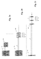
- Fig. 1 is a trigger unit 1 via a trigger line 2, composed of successive line sections 2a, 2b, 2c, ..., with retriggerable sensors 3a, 3b, 3c, ..., generally 3, in conjunction.
- the sensors 3 are each switched on between two line sections 2 a, 2 b, 2 c,... Of the trigger line 2 and thus form a cascade of any number of sensors 3.
- Each sensor 3 has an input 4 for one and an output 5 for the other adjacent line section 2a, 2b, 2c, ... and has a controllable breaker 6 between input and output 4, 5 and one connected to the input 4 , the interruptor 6 controlling control circuit. 7
- the breaker 6 of all sensors 3 are open, as in Fig. 1 shown.
- the control circuit 7 opens the breaker 6 on request, for example, a regularly repeated, automatic request by the trigger unit 1, including this, for example, a specific signal (not shown) via the trigger line 2 and the input 4 or an optional data bus 8 and a data bus connection 9 of the sensor 3 sends; the breaker 6 can also be opened by hand at the factory or during installation and, if desired, after a single calibration of the control circuit 7 are also permanently closed.
- the trigger unit 1 transmits in accordance with the Fig. 2a to 2c Stepwise individual trigger pulses 10a, 10b, 10c, ... generally 10, via the trigger line 2, u.zw. Initially, only the first trigger pulse 10a via the first line section 2a of the trigger line 2, since all interrupters 6 are opened, to the sensors 3, here initially only the first sensor 3a of the cascade. If a trigger pulse 10 at the input 4 is received at a sensor 3 in the calibration mode with the interrupter 6 open, the respective sensor 3 returns a response to the trigger unit 1 by means of its control circuit 7 and then closes the interrupter 6. The trigger unit 1 receives the answer and can calibrate based on the received response to the respective sensor 3, as will be explained later.
- the trigger unit 1 sends a further trigger pulse 10 for each each further sensor 3 until the trigger unit 1 no longer receives a response to a trigger pulse 10;
- a maximum number of trigger pulses 10 can be preset, which the trigger unit 1 should emit.
- the sensor 3 in a first embodiment 3a reflects according to the example of FIG Fig. 2a simply the trigger pulse 10a by means of a reflector as a reflected trigger pulse 10a 'at the input 4.
- the reflector is formed in the simplest case by the breaker 6 in the open state. Then the control circuit 7 closes the breaker 6 of the sensor 3a.
- the trigger unit 1 measures the transit time t 1 of the emitted trigger pulse 10 a, 10 a 'reflected by the sensor 3 a and is calibrated thereon.
- the thus measured transit time t 1 which corresponds to a length l 1 of the trigger line 2 between the trigger unit 1 and the considered sensor 3a, here the length l 1 of the line section 2a, can later in an operating mode in which the sensor 3a by means of its sensor circuit 11 measurements are taken into account.
- the trigger unit 1 is based on further transit times t 2 , t 3 ,..., Generally t n , or further cumulative line lengths l 2 , l 3 ,..., Generally I n , to further sensors 3 b, 3c, ... the cascade calibrated until the trigger unit 1 no longer receives a response to a trigger pulse 10.
- each sensor 3 has a unique identifier ID, for example stored in a memory 12, as well as a modulator 13.
- Fig. 2b 2 shows an example of an embodiment in which the second sensor 3b of the cascade reflects a second trigger pulse 10b and the reflected trigger pulse 10b '. modulated by the modulator 13 with its identifier ID. Again, this can be repeated step by step for all sensors 3 on the trigger line 2.
- the trigger unit 1 identifies in this way the sequence of the sensors 3 on the trigger line 2 on the basis of the sequence of incoming identifications ID of the sensors 3 and can be calibrated in addition to the transit times t n on it or alternatively to the transit times t n only.
- the modulator 13 is designed as a make contact 14 with an RF driver 15 controlled by the control circuit 7.
- the closer 14 is a reflector in this embodiment and closes the exemplified trigger line 2, which has a defined characteristic impedance, short to ground; trigger line 2 may have any structure of waveguides known in the art, eg, a coaxial trigger line 2.
- the shutter 14 has the task of causing a controlled by the RF driver 15 deviation from the defined characteristic impedance of the trigger line 2 and to bring about a reflection; For example, he can form a short circuit to ground, as in Fig. 1 shown.
- the breaker 6 is preferably completed in the open state with the characteristic impedance of the trigger line 2, so that there are no reflections on the interrupter 6 itself, which eliminates a separation against a reflection on the shutter 14 itself.
- Such a breaker 6 is realized, for example, by an SPDT switch (single pole, double throw) in which a first connection with the characteristic impedance of the trigger line 2 is completed and a second connection is connected to output 5.
- the closer 14 could alternatively be formed by the controlled by the RF driver 15 breaker 6 and, for example, as SPTT switch (Single Pole, Triple Throw) to be constructed, the first terminal of the Idle forms whose second terminal is terminated with the characteristic impedance of the trigger line 2 and the third terminal is connected to the output 5.
- SPTT switch Single Pole, Triple Throw
- SPDT or SPTT switches can be realized in high-frequency semiconductor circuit technology.
- the identifier ID is in the example of Fig. 1 firmly integrated with its memory 12 in each sensor 3, eg programmed; Alternatively, the memory 12 could also be inserted into the sensor 3 in the manner of a SIM card as a separate module from the sensor 3.
- the ID tag is coded as a 4-bit tag with a prefix start bit 16, but could have any other code length and encoding.
- the reflected trigger pulse 10b 'could also be frequency or phase modulated instead of amplitude and / or have an additional stop bit.
- the third sensor 3c of the cascade used can return its identifier ID in the calibration mode in the form of a modulated identification pulse 17 as the sole response or following the reflected trigger pulse 10c '.
- the calibration can be done stepwise in this way for all sensors 3 on the trigger line 2.
- the trigger unit 1 identifies the order of the sensors 3 on the trigger line 2 based on the sequence of incoming IDs of each sensor 3 and is calibrated on it alone or in addition.
- the tag pulse 17 may be, as described above with respect to the reflected trigger pulse 10b ', provided with start bit 16 and encoded with 4-bit length or otherwise composed and is also generated by the modulator 13.
- the modulator 13 is in this embodiment either separately powered, for example via an external power supply (not shown), wherein the signal power of the identification pulse 17 adapted and so can be increased to compensate for any line losses; or the energy necessary for forming and transmitting the identification pulse is taken from the trigger pulse 10c itself, for which purpose the sensor 3c can have an energy store, eg a capacitor (not shown). If the modulator 13 is separately powered, the trigger pulse 10c may be very short, as in FIG Fig. 2c shown; if, on the other hand, the energy for the identification pulse 17 is to be taken from the trigger pulse 10c, then it is of correspondingly longer duration and / or more powerful.
- control circuit 7 of a sensor 3 may also be designed to output the identifier ID for calibrating the trigger unit 1 at the data bus connection 9 following the reflected trigger pulse 10 'or instead of such to return the data bus 8 to the trigger unit 1.
- the trigger unit 1 identifies the order of the sensors 3 on the trigger line 2 stepwise by the sequence of incoming IDs of each sensor 3.
- sensors 3 of the cascade can be designed in the same form and thus the trigger unit 1 can calibrate to all sensors 3 in the same way;
- sensors 3 of different embodiments 3a-3c according to FIG Fig.1 are combined in a single cascade and the trigger unit 1 according to the in the Fig. 2a - 2c shown variants or the variant of identifying the sensors 3 are calibrated via the data bus 8.
- the sensor circuit 11 of each sensor 3 is triggered as required by the trigger unit 1 via the trigger line 2, thus triggering a measuring operation of the sensor 3 or its sensor circuit 11.
- the control circuit 7 and the sensor circuit 11 can in this case via the data bus 8 and the data bus connection 9 receive possible setting values and / or the sensor circuit 11 output measured values about it.
- the sensor circuit 11 of the example of FIG Fig. 1 has a radar transmitter and / or receiver 11 ', however, the sensors 3 and the inventive method are not limited to radar sensors, but can be applied in the same way in other sensor technologies.
- the sensor circuit 11 can be permanently connected to the input 4 and thus receive the trigger pulse 10 sent in the operating mode from the trigger unit 1 via the trigger line 2.
- the control circuit 7 is designed to apply in the operating mode the trigger pulse 10 received at the input 4 to the sensor circuit 11 by means of a controlled trigger switch 18 when a measuring operation of the sensor circuit 11 of the sensor 3 is to be triggered.
- the interrupters 6 of the sensors 3 connected in cascade are generally closed in order to keep all sensors of the cascade operational in the operating mode.
Landscapes
- Engineering & Computer Science (AREA)
- Radar, Positioning & Navigation (AREA)
- Remote Sensing (AREA)
- Computer Networks & Wireless Communication (AREA)
- Physics & Mathematics (AREA)
- General Physics & Mathematics (AREA)
- Radar Systems Or Details Thereof (AREA)
- Testing Or Calibration Of Command Recording Devices (AREA)
- Arrangements For Transmission Of Measured Signals (AREA)
- Investigating Or Analyzing Materials By The Use Of Electric Means (AREA)
Claims (11)
- Procédé d'étalonnage d'une unité de déclenchement (1), laquelle est en connexion, par l'intermédiaire d'une ligne (2) de déclenchement, avec au moins deux capteurs (3) pouvant être déclenchés, qui sont chacun intercalé entre deux tronçons de ligne (2a, 2b, 2c) successifs de la ligne (2) de déclenchement, dans lequel chaque capteur (3) présente une entrée (4) pour l'un des tronçons de ligne (2a, 2b, 2c) et une sortie (5) pour l'autre tronçon de ligne (2a, 2b, 2c), un disjoncteur (6) pouvant être commandé entre l'entrée et la sortie (4, 5) et un circuit de commande (7) relié à l'entrée (4), commandant le disjoncteur (6), dans lequel les disjoncteurs (6) de tous les capteurs (3) sont d'abord ouverts, avec les étapes :d'émission d'une impulsion de déclenchement (10) à partir de l'unité de déclenchement (1) par l'intermédiaire d'au moins un tronçon de ligne (2a, 2b, 2c) vers un capteur (3) ;dans le capteur (3) : de réception de l'impulsion de déclenchement (10) et, lorsque le disjoncteur (6) est ouvert, de renvoi d'une réponse vers l'unité de déclenchement (1) ainsi que de fermeture du disjoncteur (6) ;dans l'unité de déclenchement (1) : de réception de la réponse et d'étalonnage de l'unité de déclenchement (1) par rapport au capteur (3) à l'aide de la réponse réceptionnée ;de répétition des étapes précitées pour chaque autre capteur (3) jusqu'à ce que l'unité de déclenchement (1) ne réceptionne plus de réponse à une impulsion de déclenchement (10) ou jusqu'à un nombre maximal préréglé d'impulsions de déclenchement (10) émises est atteint ;caractérisé en ce quechaque capteur (3) reflète en tant que résponse l'impulsion de déclenchement (10) et l'unité de déclenchement (1) mesure les temps de parcours (tn) des impulsions de déclenchement (10, 10') émises et reflétées par les capteurs (3) respectifs et est étalonnée en fonction de celles-ci.
- Procédé selon la revendication 1, dans lequel chaque capteur (3) a une identification (ID) unique et module l'impulsion de déclenchement (10') reflétée avec son identification (ID), et l'unité de déclenchement (1) identifie la série des capteurs (3) sur la ligne de déclenchement (2) à l'aide de la suite des identifications (ID) arrivant et est également étalonnée en fonction de celles-ci.
- Procédé selon la revendication 1, dans lequel chaque capteur (3) a une identification (ID) unique et renvoie à la suite de l'impulsion de déclenchement (10') reflétée également une impulsion d'identification (17) modulée avec son identification (ID), et l'unité de déclenchement (1) identifie la série des capteurs (3) sur la ligne de déclenchement (2) à l'aide de la suite des identifications (ID) arrivant et est également étalonnée en fonction de celles-ci.
- Procédé selon la revendication 1, dans lequel chaque capteur (3) a une identification (ID) unique et renvoie à la suite de l'impulsion de déclenchement (10') reflétée également l'identification (ID) vers l'unité de déclenchement (1) par l'intermédiaire d'un bus de données (8), et l'unité de déclenchement (1) identifie la série des capteurs (3) sur la ligne de déclenchement (2) à l'aide de la suite des identifications (ID) arrivant et est également étalonnée en fonction de celles-ci.
- Capteur en cascade, qui peut être intercalé avec une entrée (4) et une sortie (5) entre deux tronçons de ligne (2a, 2b, 2c) d'une ligne de déclenchement (2), comprenant :un circuit de capteur (11) pouvant être déclenché, un disjoncteur (6) pouvant être commandé entre une entrée et une sortie (4, 5), et un circuit de commande (7) relié à l'entrée (4), commandant le disjoncteur (6),dans lequel le circuit de commande (7) est conçu pourdans un mode d'étalonnage : ouvrir tout d'abord le disjoncteur (6) et après la réception d'une première impulsion de déclenchement (10) à l'entrée (4), émettre une réponse à l'entrée (4) et fermer le disjoncteur (6); etdans un mode de fonctionnement : appliquer une impulsion de déclenchement (10) réceptionnée à l'entrée (4), au circuit de capteur (11), caractérisé en ce quele capteur comprend en outre une mémoire (12) avec une identification (ID) unique et un modulateur (13) relié à l'entrée (4), dans lequel le circuit de commande (7) est conçu pour refléter en tant que réponse l'impulsion de déclenchement (10) à l'entrée (4) dans le mode d'étalonnage, et renvoyer une impulsion d'identification (17) modulée avec l'identification (ID) à l'aide du modulateur (13).
- Capteur selon la revendication 5, comprenant en outre, à l'entrée (4), un réflecteur pouvant être commuté par le circuit de commande (7).
- Capteur selon la revendication 6, dans lequel le réflecteur est formé par le disjoncteur (6) à l'état ouvert.
- Capteur selon la revendication 6, comprenant en outre une mémoire (12) avec une identification (ID) unique et un modulateur (13) relié l'entrée (4), dans lequel le circuit de commande (7) est conçu pour moduler l'impulsion de déclenchement (10') reflétée avec l'identification (ID) à l'aide du modulateur (13).
- Capteur selon la revendication 6, comprenant en outre une mémoire (12) avec une identification (ID) unique et un modulateur (13) relié à l'entrée (4), dans lequel le circuit de commande (7) est conçu pour renvoyer également l'impulsion d'identification (17) modulée à l'aide du modulateur (13) avec l'identification (ID) à la suite de l'impulsion de déclenchement (10') reflétée.
- Capteur selon la revendication 6, comprenant en outre une mémoire (12) avec une identification (ID) unique, dans lequel le circuit de commande (7) est conçu pour émettre à la suite de l'impulsion de déclenchement (10') reflétée également l'identification (ID) à un raccordement d'un bus de données (9).
- Capteur selon l'une des revendications 5 à 10, dans lequel le circuit de capteur (11) est un circuit de capteur radar.
Priority Applications (12)
| Application Number | Priority Date | Filing Date | Title |
|---|---|---|---|
| EP13167408.7A EP2804010B1 (fr) | 2013-05-13 | 2013-05-13 | Procédé d'étalonnage d'une unité de déclenchement et capteur à montage en cascade correspondant |
| SI201330136T SI2804010T1 (sl) | 2013-05-13 | 2013-05-13 | Postopek za kalibriranje prožilne enote in kaskadno razmestljiv senzor v ta namen |
| DK13167408.7T DK2804010T3 (en) | 2013-05-13 | 2013-05-13 | METHOD FOR CALIBRATION OF A TRIGGER DEVICE AND cascadable SENSOR THEREFOR |
| PT131674087T PT2804010E (pt) | 2013-05-13 | 2013-05-13 | Método para calibrar uma unidade de disparo e sensor em cascata correspondente |
| ES13167408.7T ES2563055T3 (es) | 2013-05-13 | 2013-05-13 | Procedimiento para el calibrado de una unidad de disparo y sensor conectable en cascada correspondiente |
| PL13167408T PL2804010T3 (pl) | 2013-05-13 | 2013-05-13 | Sposób kalibracji jednostki wyzwalającej i przeznaczony do niego czujnik do montażu kaskadowego |
| CA2847737A CA2847737A1 (fr) | 2013-05-13 | 2014-03-31 | Procede de calibration d'une unite de declenchement et capteur en cascade correspondant |
| AU2014201980A AU2014201980B2 (en) | 2013-05-13 | 2014-04-08 | Method for Calibrating a Trigger Unit and Cascadable Sensor therefor |
| NZ623420A NZ623420A (en) | 2013-05-13 | 2014-04-08 | Method for calibrating a trigger unit and cascadable sensor therefor |
| US14/266,246 US9494450B2 (en) | 2013-05-13 | 2014-04-30 | Method for calibrating a trigger unit and cascadable sensor therefor |
| ZA2014/03402A ZA201403402B (en) | 2013-05-13 | 2014-05-12 | Method for calibrating a trigger unit and cascadable sensor thereof |
| RU2014118955/07A RU2014118955A (ru) | 2013-05-13 | 2014-05-12 | Способ калибровки пускового устройства и каскадный датчик для него |
Applications Claiming Priority (1)
| Application Number | Priority Date | Filing Date | Title |
|---|---|---|---|
| EP13167408.7A EP2804010B1 (fr) | 2013-05-13 | 2013-05-13 | Procédé d'étalonnage d'une unité de déclenchement et capteur à montage en cascade correspondant |
Publications (2)
| Publication Number | Publication Date |
|---|---|
| EP2804010A1 EP2804010A1 (fr) | 2014-11-19 |
| EP2804010B1 true EP2804010B1 (fr) | 2015-12-02 |
Family
ID=48325497
Family Applications (1)
| Application Number | Title | Priority Date | Filing Date |
|---|---|---|---|
| EP13167408.7A Not-in-force EP2804010B1 (fr) | 2013-05-13 | 2013-05-13 | Procédé d'étalonnage d'une unité de déclenchement et capteur à montage en cascade correspondant |
Country Status (12)
| Country | Link |
|---|---|
| US (1) | US9494450B2 (fr) |
| EP (1) | EP2804010B1 (fr) |
| AU (1) | AU2014201980B2 (fr) |
| CA (1) | CA2847737A1 (fr) |
| DK (1) | DK2804010T3 (fr) |
| ES (1) | ES2563055T3 (fr) |
| NZ (1) | NZ623420A (fr) |
| PL (1) | PL2804010T3 (fr) |
| PT (1) | PT2804010E (fr) |
| RU (1) | RU2014118955A (fr) |
| SI (1) | SI2804010T1 (fr) |
| ZA (1) | ZA201403402B (fr) |
Families Citing this family (3)
| Publication number | Priority date | Publication date | Assignee | Title |
|---|---|---|---|---|
| US10079650B2 (en) * | 2015-12-04 | 2018-09-18 | Infineon Technologies Ag | Robust high speed sensor interface for remote sensors |
| DE102019212414A1 (de) | 2019-08-20 | 2021-02-25 | Conti Temic Microelectronic Gmbh | Verfahren zur Positionserkennung eines Busteilnehmers |
| DE102019212415A1 (de) | 2019-08-20 | 2021-02-25 | Conti Temic Microelectronic Gmbh | Verfahren zur Positionserkennung eines Busteilnehmers |
Family Cites Families (21)
| Publication number | Priority date | Publication date | Assignee | Title |
|---|---|---|---|---|
| JPS53114282A (en) * | 1977-03-16 | 1978-10-05 | Tokyo Shibaura Electric Co | Ultrasonic diagnosing device |
| FR2651609B1 (fr) * | 1989-09-01 | 1992-01-03 | Thomson Csf | Commande de pointage pour systeme d'antenne a balayage electronique et formation de faisceau par le calcul. |
| US5808580A (en) * | 1997-02-06 | 1998-09-15 | Andrews, Jr.; Grealie A. | Radar/sonar system concept for extended range-doppler coverage |
| DE19740306A1 (de) * | 1997-09-13 | 1999-03-18 | Dornier Gmbh Lindauer | Erweiterter CAN-Bus zur Steuerung einer Webmaschine |
| US5940025A (en) * | 1997-09-15 | 1999-08-17 | Raytheon Company | Noise cancellation method and apparatus |
| US6069581A (en) * | 1998-02-20 | 2000-05-30 | Amerigon | High performance vehicle radar system |
| US6252542B1 (en) * | 1998-03-16 | 2001-06-26 | Thomas V. Sikina | Phased array antenna calibration system and method using array clusters |
| DE10004425A1 (de) * | 2000-02-02 | 2002-01-17 | Siemens Ag | Netzwerk sowie Netzwerkteilnehmer, insbesondere Feldgerät, für ein derartiges Netzwerk |
| US6895230B1 (en) * | 2000-08-16 | 2005-05-17 | Kathrein-Werke Kg | System and method for delay equalization of multiple transmission paths |
| US6989788B2 (en) * | 2002-09-16 | 2006-01-24 | Continental Microwave & Tool Co., Inc. | Antenna array having apparatus for producing time-delayed microwave signals using selectable time delay stages |
| DE10252091A1 (de) | 2002-11-08 | 2004-05-19 | Siemens Ag | Verfahren und Anordnung für multistatische Nachdistanzradarmessungen |
| US20060013065A1 (en) * | 2004-07-16 | 2006-01-19 | Sensorwise, Inc. | Seismic Data Acquisition System and Method for Downhole Use |
| DE102005055964A1 (de) * | 2005-11-15 | 2007-05-16 | Valeo Schalter & Sensoren Gmbh | Verfahren zum Betreiben eines Sensorsystems, Sensorsystem und Sensormodul |
| US8203484B2 (en) * | 2007-02-09 | 2012-06-19 | University Of Southern California | Path-sharing transceiver architecture for antenna arrays |
| US7649492B2 (en) * | 2007-05-25 | 2010-01-19 | Niitek, Inc. | Systems and methods for providing delayed signals |
| DE102007045561B4 (de) * | 2007-09-24 | 2018-02-15 | Robert Bosch Gmbh | Verfahren zum Betrieb eines Fahrerassistenzsystems |
| US8102785B2 (en) * | 2008-05-21 | 2012-01-24 | Alcatel Lucent | Calibrating radiofrequency paths of a phased-array antenna |
| DE102008034445B4 (de) * | 2008-07-24 | 2010-03-11 | Diehl Aerospace Gmbh | Verfahren und Einrichtung zum Erfassen von Bus-Teilnehmern |
| US8138969B2 (en) * | 2008-10-22 | 2012-03-20 | Bae Systems Information And Electronic Systems Integration Inc. | Monobit based low cost high performance radar warning receiver |
| US8330650B2 (en) * | 2010-05-07 | 2012-12-11 | The United States Of America, As Represented By The Secretary Of The Army | Radar system and antenna with delay lines and method thereof |
| US9360549B1 (en) * | 2014-06-05 | 2016-06-07 | Thales-Raytheon Systems Company Llc | Methods and apparatus for a self-calibrated signal injection setup for in-field receive phased array calibration system |
-
2013
- 2013-05-13 SI SI201330136T patent/SI2804010T1/sl unknown
- 2013-05-13 ES ES13167408.7T patent/ES2563055T3/es active Active
- 2013-05-13 PT PT131674087T patent/PT2804010E/pt unknown
- 2013-05-13 PL PL13167408T patent/PL2804010T3/pl unknown
- 2013-05-13 EP EP13167408.7A patent/EP2804010B1/fr not_active Not-in-force
- 2013-05-13 DK DK13167408.7T patent/DK2804010T3/en active
-
2014
- 2014-03-31 CA CA2847737A patent/CA2847737A1/fr not_active Abandoned
- 2014-04-08 AU AU2014201980A patent/AU2014201980B2/en not_active Ceased
- 2014-04-08 NZ NZ623420A patent/NZ623420A/en not_active IP Right Cessation
- 2014-04-30 US US14/266,246 patent/US9494450B2/en not_active Expired - Fee Related
- 2014-05-12 ZA ZA2014/03402A patent/ZA201403402B/en unknown
- 2014-05-12 RU RU2014118955/07A patent/RU2014118955A/ru not_active Application Discontinuation
Also Published As
| Publication number | Publication date |
|---|---|
| RU2014118955A (ru) | 2015-11-20 |
| PL2804010T3 (pl) | 2016-06-30 |
| SI2804010T1 (sl) | 2016-03-31 |
| EP2804010A1 (fr) | 2014-11-19 |
| CA2847737A1 (fr) | 2014-11-13 |
| DK2804010T3 (en) | 2016-03-07 |
| ZA201403402B (en) | 2015-07-29 |
| AU2014201980A1 (en) | 2014-11-27 |
| PT2804010E (pt) | 2016-03-28 |
| ES2563055T3 (es) | 2016-03-10 |
| AU2014201980B2 (en) | 2017-06-08 |
| US9494450B2 (en) | 2016-11-15 |
| NZ623420A (en) | 2014-11-28 |
| US20140331736A1 (en) | 2014-11-13 |
Similar Documents
| Publication | Publication Date | Title |
|---|---|---|
| DE102012218454B4 (de) | Selbstsynchronisierendes datenkommunikationsverfahren und selbstsynchronisierende datenkommunikationsvorrichtung | |
| EP3669500B1 (fr) | Procédé de fonctionnement d'un agencement de capteurs dans un véhicule automobile sur la base d'un protocole dsi | |
| EP1738297A2 (fr) | Procede de selection d'un ou plusieurs transpondeurs | |
| EP2804010B1 (fr) | Procédé d'étalonnage d'une unité de déclenchement et capteur à montage en cascade correspondant | |
| DE19517001A1 (de) | Verfahren und Vorrichtung zur Bestimmung der Lichtlaufzeit über eine zwischen einer Meßvorrichtung und einem reflektierenden Objekt angeordnete Meßstrecke | |
| DE4034019C1 (fr) | ||
| EP3308195B1 (fr) | Procédé de mesure de l'éloignement | |
| DE19911369A1 (de) | Oberflächen-Wellen-Wandler-Einrichtung sowie Identifikationssystem hiermit | |
| WO2009063056A1 (fr) | Procédé d'exploitation d'un appareil de terrain, unité de communication et appareil de terrain correspondants | |
| DE10248640A1 (de) | Schaltgerät sowie System und Verfahren zur Signalübertragung zwischen diesem und einer Signalverarbeitungseinheit | |
| EP0316524B1 (fr) | Système de radar à impulsions | |
| EP3669527B1 (fr) | Procédé de fonctionnement d'un agencement de capteurs dans un véhicule automobile sur la base d'un protocole dsi | |
| EP0519089B1 (fr) | Introduction de paramètres de service dans un commutateur de proximité prêt à servir | |
| DE102010006621A1 (de) | Verfahren für ein schnelles Sensorsystem | |
| DE3622800C2 (fr) | ||
| DE102005009765B3 (de) | Selektionsverfahren für eine Datenkommunikation zwischen Basisstation und Transponder | |
| EP1298851B1 (fr) | Procédé d'adressage de noeuds d'un système de bus | |
| EP0519090B1 (fr) | Commutateur de proximité ultrasonore avec équipement de synchronisation | |
| EP2788785B1 (fr) | Système de capteurs servant à faire fonctionner un système de capteurs | |
| EP3329481B1 (fr) | Procédé de transmission de données d'un capteur à un récepteur | |
| EP4018600B1 (fr) | Procédé de reconnaissance de la position d'un abonné au bus | |
| EP0871946B1 (fr) | Systeme de transmission de donnees comprenant au moins un emetteur et au moins un recepteur, et procede d'initialisation de ce systeme et de synchronisation emetteur-recepteur | |
| DE60308688T2 (de) | Anpassungsverfahren zwischen einem befehlssender und einem befehlsempfänger | |
| EP3602781A1 (fr) | Commutateur de configuration et usager de bus comportant un tel commutateur de configuration | |
| DE2809796A1 (de) | Fernbedienungsanlage fuer ein elektrisches geraet |
Legal Events
| Date | Code | Title | Description |
|---|---|---|---|
| PUAI | Public reference made under article 153(3) epc to a published international application that has entered the european phase |
Free format text: ORIGINAL CODE: 0009012 |
|
| 17P | Request for examination filed |
Effective date: 20140318 |
|
| AK | Designated contracting states |
Kind code of ref document: A1 Designated state(s): AL AT BE BG CH CY CZ DE DK EE ES FI FR GB GR HR HU IE IS IT LI LT LU LV MC MK MT NL NO PL PT RO RS SE SI SK SM TR |
|
| AX | Request for extension of the european patent |
Extension state: BA ME |
|
| GRAP | Despatch of communication of intention to grant a patent |
Free format text: ORIGINAL CODE: EPIDOSNIGR1 |
|
| INTG | Intention to grant announced |
Effective date: 20150629 |
|
| GRAS | Grant fee paid |
Free format text: ORIGINAL CODE: EPIDOSNIGR3 |
|
| GRAA | (expected) grant |
Free format text: ORIGINAL CODE: 0009210 |
|
| AK | Designated contracting states |
Kind code of ref document: B1 Designated state(s): AL AT BE BG CH CY CZ DE DK EE ES FI FR GB GR HR HU IE IS IT LI LT LU LV MC MK MT NL NO PL PT RO RS SE SI SK SM TR |
|
| REG | Reference to a national code |
Ref country code: GB Ref legal event code: FG4D Free format text: NOT ENGLISH |
|
| REG | Reference to a national code |
Ref country code: AT Ref legal event code: REF Ref document number: 763864 Country of ref document: AT Kind code of ref document: T Effective date: 20151215 Ref country code: CH Ref legal event code: EP |
|
| REG | Reference to a national code |
Ref country code: IE Ref legal event code: FG4D Free format text: LANGUAGE OF EP DOCUMENT: GERMAN |
|
| REG | Reference to a national code |
Ref country code: DE Ref legal event code: R096 Ref document number: 502013001542 Country of ref document: DE |
|
| REG | Reference to a national code |
Ref country code: DK Ref legal event code: T3 Effective date: 20160304 |
|
| REG | Reference to a national code |
Ref country code: ES Ref legal event code: FG2A Ref document number: 2563055 Country of ref document: ES Kind code of ref document: T3 Effective date: 20160310 |
|
| REG | Reference to a national code |
Ref country code: SE Ref legal event code: TRGR |
|
| REG | Reference to a national code |
Ref country code: PT Ref legal event code: SC4A Free format text: AVAILABILITY OF NATIONAL TRANSLATION Effective date: 20160218 |
|
| REG | Reference to a national code |
Ref country code: NO Ref legal event code: T2 Effective date: 20151202 Ref country code: LT Ref legal event code: MG4D |
|
| REG | Reference to a national code |
Ref country code: NL Ref legal event code: FP |
|
| PG25 | Lapsed in a contracting state [announced via postgrant information from national office to epo] |
Ref country code: LT Free format text: LAPSE BECAUSE OF FAILURE TO SUBMIT A TRANSLATION OF THE DESCRIPTION OR TO PAY THE FEE WITHIN THE PRESCRIBED TIME-LIMIT Effective date: 20151202 |
|
| REG | Reference to a national code |
Ref country code: FR Ref legal event code: PLFP Year of fee payment: 4 |
|
| PG25 | Lapsed in a contracting state [announced via postgrant information from national office to epo] |
Ref country code: GR Free format text: LAPSE BECAUSE OF FAILURE TO SUBMIT A TRANSLATION OF THE DESCRIPTION OR TO PAY THE FEE WITHIN THE PRESCRIBED TIME-LIMIT Effective date: 20160303 Ref country code: LV Free format text: LAPSE BECAUSE OF FAILURE TO SUBMIT A TRANSLATION OF THE DESCRIPTION OR TO PAY THE FEE WITHIN THE PRESCRIBED TIME-LIMIT Effective date: 20151202 Ref country code: RS Free format text: LAPSE BECAUSE OF FAILURE TO SUBMIT A TRANSLATION OF THE DESCRIPTION OR TO PAY THE FEE WITHIN THE PRESCRIBED TIME-LIMIT Effective date: 20151202 Ref country code: FI Free format text: LAPSE BECAUSE OF FAILURE TO SUBMIT A TRANSLATION OF THE DESCRIPTION OR TO PAY THE FEE WITHIN THE PRESCRIBED TIME-LIMIT Effective date: 20151202 |
|
| PG25 | Lapsed in a contracting state [announced via postgrant information from national office to epo] |
Ref country code: IS Free format text: LAPSE BECAUSE OF FAILURE TO SUBMIT A TRANSLATION OF THE DESCRIPTION OR TO PAY THE FEE WITHIN THE PRESCRIBED TIME-LIMIT Effective date: 20151202 |
|
| PGFP | Annual fee paid to national office [announced via postgrant information from national office to epo] |
Ref country code: NL Payment date: 20160519 Year of fee payment: 4 |
|
| REG | Reference to a national code |
Ref country code: SK Ref legal event code: T3 Ref document number: E 20388 Country of ref document: SK |
|
| PGFP | Annual fee paid to national office [announced via postgrant information from national office to epo] |
Ref country code: CH Payment date: 20160519 Year of fee payment: 4 Ref country code: CZ Payment date: 20160512 Year of fee payment: 4 Ref country code: NO Payment date: 20160524 Year of fee payment: 4 |
|
| PG25 | Lapsed in a contracting state [announced via postgrant information from national office to epo] |
Ref country code: RO Free format text: LAPSE BECAUSE OF FAILURE TO SUBMIT A TRANSLATION OF THE DESCRIPTION OR TO PAY THE FEE WITHIN THE PRESCRIBED TIME-LIMIT Effective date: 20151202 Ref country code: BE Free format text: LAPSE BECAUSE OF NON-PAYMENT OF DUE FEES Effective date: 20160531 Ref country code: IS Free format text: LAPSE BECAUSE OF FAILURE TO SUBMIT A TRANSLATION OF THE DESCRIPTION OR TO PAY THE FEE WITHIN THE PRESCRIBED TIME-LIMIT Effective date: 20160402 Ref country code: EE Free format text: LAPSE BECAUSE OF FAILURE TO SUBMIT A TRANSLATION OF THE DESCRIPTION OR TO PAY THE FEE WITHIN THE PRESCRIBED TIME-LIMIT Effective date: 20151202 Ref country code: SM Free format text: LAPSE BECAUSE OF FAILURE TO SUBMIT A TRANSLATION OF THE DESCRIPTION OR TO PAY THE FEE WITHIN THE PRESCRIBED TIME-LIMIT Effective date: 20151202 |
|
| PGFP | Annual fee paid to national office [announced via postgrant information from national office to epo] |
Ref country code: DK Payment date: 20160519 Year of fee payment: 4 Ref country code: PL Payment date: 20160506 Year of fee payment: 4 Ref country code: PT Payment date: 20160511 Year of fee payment: 4 Ref country code: IT Payment date: 20160531 Year of fee payment: 4 Ref country code: SK Payment date: 20160511 Year of fee payment: 4 Ref country code: SI Payment date: 20160426 Year of fee payment: 4 |
|
| REG | Reference to a national code |
Ref country code: DE Ref legal event code: R097 Ref document number: 502013001542 Country of ref document: DE |
|
| PLBE | No opposition filed within time limit |
Free format text: ORIGINAL CODE: 0009261 |
|
| STAA | Information on the status of an ep patent application or granted ep patent |
Free format text: STATUS: NO OPPOSITION FILED WITHIN TIME LIMIT |
|
| 26N | No opposition filed |
Effective date: 20160905 |
|
| PG25 | Lapsed in a contracting state [announced via postgrant information from national office to epo] |
Ref country code: LU Free format text: LAPSE BECAUSE OF FAILURE TO SUBMIT A TRANSLATION OF THE DESCRIPTION OR TO PAY THE FEE WITHIN THE PRESCRIBED TIME-LIMIT Effective date: 20160513 |
|
| REG | Reference to a national code |
Ref country code: IE Ref legal event code: MM4A |
|
| REG | Reference to a national code |
Ref country code: FR Ref legal event code: PLFP Year of fee payment: 5 |
|
| PG25 | Lapsed in a contracting state [announced via postgrant information from national office to epo] |
Ref country code: IE Free format text: LAPSE BECAUSE OF NON-PAYMENT OF DUE FEES Effective date: 20160513 |
|
| PGFP | Annual fee paid to national office [announced via postgrant information from national office to epo] |
Ref country code: FR Payment date: 20170523 Year of fee payment: 5 Ref country code: DE Payment date: 20170523 Year of fee payment: 5 |
|
| PGFP | Annual fee paid to national office [announced via postgrant information from national office to epo] |
Ref country code: ES Payment date: 20170628 Year of fee payment: 5 Ref country code: SE Payment date: 20170519 Year of fee payment: 5 |
|
| REG | Reference to a national code |
Ref country code: NO Ref legal event code: MMEP |
|
| REG | Reference to a national code |
Ref country code: CH Ref legal event code: PL |
|
| REG | Reference to a national code |
Ref country code: DK Ref legal event code: EBP Effective date: 20170531 |
|
| REG | Reference to a national code |
Ref country code: NL Ref legal event code: MM Effective date: 20170601 |
|
| GBPC | Gb: european patent ceased through non-payment of renewal fee |
Effective date: 20170513 |
|
| PG25 | Lapsed in a contracting state [announced via postgrant information from national office to epo] |
Ref country code: NO Free format text: LAPSE BECAUSE OF NON-PAYMENT OF DUE FEES Effective date: 20170531 Ref country code: CZ Free format text: LAPSE BECAUSE OF NON-PAYMENT OF DUE FEES Effective date: 20170513 Ref country code: SK Free format text: LAPSE BECAUSE OF NON-PAYMENT OF DUE FEES Effective date: 20170513 |
|
| REG | Reference to a national code |
Ref country code: SK Ref legal event code: MM4A Ref document number: E 20388 Country of ref document: SK Effective date: 20170513 |
|
| PG25 | Lapsed in a contracting state [announced via postgrant information from national office to epo] |
Ref country code: CH Free format text: LAPSE BECAUSE OF NON-PAYMENT OF DUE FEES Effective date: 20170531 Ref country code: SI Free format text: LAPSE BECAUSE OF NON-PAYMENT OF DUE FEES Effective date: 20170514 Ref country code: PT Free format text: LAPSE BECAUSE OF NON-PAYMENT OF DUE FEES Effective date: 20171113 Ref country code: LI Free format text: LAPSE BECAUSE OF NON-PAYMENT OF DUE FEES Effective date: 20170531 |
|
| REG | Reference to a national code |
Ref country code: SI Ref legal event code: KO00 Effective date: 20180111 |
|
| PG25 | Lapsed in a contracting state [announced via postgrant information from national office to epo] |
Ref country code: NL Free format text: LAPSE BECAUSE OF NON-PAYMENT OF DUE FEES Effective date: 20170601 |
|
| PG25 | Lapsed in a contracting state [announced via postgrant information from national office to epo] |
Ref country code: DK Free format text: LAPSE BECAUSE OF NON-PAYMENT OF DUE FEES Effective date: 20170531 Ref country code: GB Free format text: LAPSE BECAUSE OF NON-PAYMENT OF DUE FEES Effective date: 20170513 |
|
| PG25 | Lapsed in a contracting state [announced via postgrant information from national office to epo] |
Ref country code: HU Free format text: LAPSE BECAUSE OF FAILURE TO SUBMIT A TRANSLATION OF THE DESCRIPTION OR TO PAY THE FEE WITHIN THE PRESCRIBED TIME-LIMIT; INVALID AB INITIO Effective date: 20130513 Ref country code: IT Free format text: LAPSE BECAUSE OF NON-PAYMENT OF DUE FEES Effective date: 20170513 |
|
| PG25 | Lapsed in a contracting state [announced via postgrant information from national office to epo] |
Ref country code: MC Free format text: LAPSE BECAUSE OF FAILURE TO SUBMIT A TRANSLATION OF THE DESCRIPTION OR TO PAY THE FEE WITHIN THE PRESCRIBED TIME-LIMIT Effective date: 20151202 Ref country code: CY Free format text: LAPSE BECAUSE OF FAILURE TO SUBMIT A TRANSLATION OF THE DESCRIPTION OR TO PAY THE FEE WITHIN THE PRESCRIBED TIME-LIMIT Effective date: 20151202 Ref country code: HR Free format text: LAPSE BECAUSE OF FAILURE TO SUBMIT A TRANSLATION OF THE DESCRIPTION OR TO PAY THE FEE WITHIN THE PRESCRIBED TIME-LIMIT Effective date: 20151202 Ref country code: MT Free format text: LAPSE BECAUSE OF FAILURE TO SUBMIT A TRANSLATION OF THE DESCRIPTION OR TO PAY THE FEE WITHIN THE PRESCRIBED TIME-LIMIT Effective date: 20151202 Ref country code: MK Free format text: LAPSE BECAUSE OF FAILURE TO SUBMIT A TRANSLATION OF THE DESCRIPTION OR TO PAY THE FEE WITHIN THE PRESCRIBED TIME-LIMIT Effective date: 20151202 |
|
| PG25 | Lapsed in a contracting state [announced via postgrant information from national office to epo] |
Ref country code: BG Free format text: LAPSE BECAUSE OF FAILURE TO SUBMIT A TRANSLATION OF THE DESCRIPTION OR TO PAY THE FEE WITHIN THE PRESCRIBED TIME-LIMIT Effective date: 20151202 |
|
| PG25 | Lapsed in a contracting state [announced via postgrant information from national office to epo] |
Ref country code: AL Free format text: LAPSE BECAUSE OF FAILURE TO SUBMIT A TRANSLATION OF THE DESCRIPTION OR TO PAY THE FEE WITHIN THE PRESCRIBED TIME-LIMIT Effective date: 20151202 Ref country code: TR Free format text: LAPSE BECAUSE OF FAILURE TO SUBMIT A TRANSLATION OF THE DESCRIPTION OR TO PAY THE FEE WITHIN THE PRESCRIBED TIME-LIMIT Effective date: 20151202 Ref country code: PL Free format text: LAPSE BECAUSE OF NON-PAYMENT OF DUE FEES Effective date: 20170513 |
|
| REG | Reference to a national code |
Ref country code: DE Ref legal event code: R119 Ref document number: 502013001542 Country of ref document: DE |
|
| REG | Reference to a national code |
Ref country code: SE Ref legal event code: EUG |
|
| PG25 | Lapsed in a contracting state [announced via postgrant information from national office to epo] |
Ref country code: SE Free format text: LAPSE BECAUSE OF NON-PAYMENT OF DUE FEES Effective date: 20180514 |
|
| PG25 | Lapsed in a contracting state [announced via postgrant information from national office to epo] |
Ref country code: FR Free format text: LAPSE BECAUSE OF NON-PAYMENT OF DUE FEES Effective date: 20180531 Ref country code: DE Free format text: LAPSE BECAUSE OF NON-PAYMENT OF DUE FEES Effective date: 20181201 |
|
| REG | Reference to a national code |
Ref country code: AT Ref legal event code: MM01 Ref document number: 763864 Country of ref document: AT Kind code of ref document: T Effective date: 20180513 |
|
| REG | Reference to a national code |
Ref country code: ES Ref legal event code: FD2A Effective date: 20190913 |
|
| PG25 | Lapsed in a contracting state [announced via postgrant information from national office to epo] |
Ref country code: AT Free format text: LAPSE BECAUSE OF NON-PAYMENT OF DUE FEES Effective date: 20180513 Ref country code: ES Free format text: LAPSE BECAUSE OF NON-PAYMENT OF DUE FEES Effective date: 20180514 |