EP2803842A1 - Control device for internal combustion engine - Google Patents
Control device for internal combustion engine Download PDFInfo
- Publication number
- EP2803842A1 EP2803842A1 EP12864922.5A EP12864922A EP2803842A1 EP 2803842 A1 EP2803842 A1 EP 2803842A1 EP 12864922 A EP12864922 A EP 12864922A EP 2803842 A1 EP2803842 A1 EP 2803842A1
- Authority
- EP
- European Patent Office
- Prior art keywords
- intake air
- control
- air amount
- amount
- ignition timing
- Prior art date
- Legal status (The legal status is an assumption and is not a legal conclusion. Google has not performed a legal analysis and makes no representation as to the accuracy of the status listed.)
- Granted
Links
Images


Classifications
-
- F—MECHANICAL ENGINEERING; LIGHTING; HEATING; WEAPONS; BLASTING
- F02—COMBUSTION ENGINES; HOT-GAS OR COMBUSTION-PRODUCT ENGINE PLANTS
- F02D—CONTROLLING COMBUSTION ENGINES
- F02D41/00—Electrical control of supply of combustible mixture or its constituents
- F02D41/0002—Controlling intake air
- F02D41/0007—Controlling intake air for control of turbo-charged or super-charged engines
-
- F—MECHANICAL ENGINEERING; LIGHTING; HEATING; WEAPONS; BLASTING
- F01—MACHINES OR ENGINES IN GENERAL; ENGINE PLANTS IN GENERAL; STEAM ENGINES
- F01N—GAS-FLOW SILENCERS OR EXHAUST APPARATUS FOR MACHINES OR ENGINES IN GENERAL; GAS-FLOW SILENCERS OR EXHAUST APPARATUS FOR INTERNAL COMBUSTION ENGINES
- F01N9/00—Electrical control of exhaust gas treating apparatus
-
- F—MECHANICAL ENGINEERING; LIGHTING; HEATING; WEAPONS; BLASTING
- F02—COMBUSTION ENGINES; HOT-GAS OR COMBUSTION-PRODUCT ENGINE PLANTS
- F02B—INTERNAL-COMBUSTION PISTON ENGINES; COMBUSTION ENGINES IN GENERAL
- F02B37/00—Engines characterised by provision of pumps driven at least for part of the time by exhaust
- F02B37/12—Control of the pumps
- F02B37/16—Control of the pumps by bypassing charging air
-
- F—MECHANICAL ENGINEERING; LIGHTING; HEATING; WEAPONS; BLASTING
- F02—COMBUSTION ENGINES; HOT-GAS OR COMBUSTION-PRODUCT ENGINE PLANTS
- F02B—INTERNAL-COMBUSTION PISTON ENGINES; COMBUSTION ENGINES IN GENERAL
- F02B37/00—Engines characterised by provision of pumps driven at least for part of the time by exhaust
- F02B37/12—Control of the pumps
- F02B37/18—Control of the pumps by bypassing exhaust from the inlet to the outlet of turbine or to the atmosphere
- F02B37/183—Arrangements of bypass valves or actuators therefor
- F02B37/186—Arrangements of actuators or linkage for bypass valves
-
- F—MECHANICAL ENGINEERING; LIGHTING; HEATING; WEAPONS; BLASTING
- F02—COMBUSTION ENGINES; HOT-GAS OR COMBUSTION-PRODUCT ENGINE PLANTS
- F02D—CONTROLLING COMBUSTION ENGINES
- F02D23/00—Controlling engines characterised by their being supercharged
-
- F—MECHANICAL ENGINEERING; LIGHTING; HEATING; WEAPONS; BLASTING
- F02—COMBUSTION ENGINES; HOT-GAS OR COMBUSTION-PRODUCT ENGINE PLANTS
- F02D—CONTROLLING COMBUSTION ENGINES
- F02D37/00—Non-electrical conjoint control of two or more functions of engines, not otherwise provided for
- F02D37/02—Non-electrical conjoint control of two or more functions of engines, not otherwise provided for one of the functions being ignition
-
- F—MECHANICAL ENGINEERING; LIGHTING; HEATING; WEAPONS; BLASTING
- F02—COMBUSTION ENGINES; HOT-GAS OR COMBUSTION-PRODUCT ENGINE PLANTS
- F02D—CONTROLLING COMBUSTION ENGINES
- F02D41/00—Electrical control of supply of combustible mixture or its constituents
- F02D41/0002—Controlling intake air
-
- F—MECHANICAL ENGINEERING; LIGHTING; HEATING; WEAPONS; BLASTING
- F02—COMBUSTION ENGINES; HOT-GAS OR COMBUSTION-PRODUCT ENGINE PLANTS
- F02D—CONTROLLING COMBUSTION ENGINES
- F02D41/00—Electrical control of supply of combustible mixture or its constituents
- F02D41/02—Circuit arrangements for generating control signals
- F02D41/021—Introducing corrections for particular conditions exterior to the engine
- F02D41/0235—Introducing corrections for particular conditions exterior to the engine in relation with the state of the exhaust gas treating apparatus
- F02D41/024—Introducing corrections for particular conditions exterior to the engine in relation with the state of the exhaust gas treating apparatus to increase temperature of the exhaust gas treating apparatus
-
- F—MECHANICAL ENGINEERING; LIGHTING; HEATING; WEAPONS; BLASTING
- F02—COMBUSTION ENGINES; HOT-GAS OR COMBUSTION-PRODUCT ENGINE PLANTS
- F02D—CONTROLLING COMBUSTION ENGINES
- F02D41/00—Electrical control of supply of combustible mixture or its constituents
- F02D41/02—Circuit arrangements for generating control signals
- F02D41/04—Introducing corrections for particular operating conditions
- F02D41/06—Introducing corrections for particular operating conditions for engine starting or warming up
- F02D41/068—Introducing corrections for particular operating conditions for engine starting or warming up for warming-up
-
- F—MECHANICAL ENGINEERING; LIGHTING; HEATING; WEAPONS; BLASTING
- F02—COMBUSTION ENGINES; HOT-GAS OR COMBUSTION-PRODUCT ENGINE PLANTS
- F02D—CONTROLLING COMBUSTION ENGINES
- F02D41/00—Electrical control of supply of combustible mixture or its constituents
- F02D41/02—Circuit arrangements for generating control signals
- F02D41/04—Introducing corrections for particular operating conditions
- F02D41/08—Introducing corrections for particular operating conditions for idling
- F02D41/086—Introducing corrections for particular operating conditions for idling taking into account the temperature of the engine
-
- F—MECHANICAL ENGINEERING; LIGHTING; HEATING; WEAPONS; BLASTING
- F02—COMBUSTION ENGINES; HOT-GAS OR COMBUSTION-PRODUCT ENGINE PLANTS
- F02D—CONTROLLING COMBUSTION ENGINES
- F02D9/00—Controlling engines by throttling air or fuel-and-air induction conduits or exhaust conduits
- F02D9/02—Controlling engines by throttling air or fuel-and-air induction conduits or exhaust conduits concerning induction conduits
-
- F—MECHANICAL ENGINEERING; LIGHTING; HEATING; WEAPONS; BLASTING
- F02—COMBUSTION ENGINES; HOT-GAS OR COMBUSTION-PRODUCT ENGINE PLANTS
- F02P—IGNITION, OTHER THAN COMPRESSION IGNITION, FOR INTERNAL-COMBUSTION ENGINES; TESTING OF IGNITION TIMING IN COMPRESSION-IGNITION ENGINES
- F02P5/00—Advancing or retarding ignition; Control therefor
- F02P5/04—Advancing or retarding ignition; Control therefor automatically, as a function of the working conditions of the engine or vehicle or of the atmospheric conditions
- F02P5/045—Advancing or retarding ignition; Control therefor automatically, as a function of the working conditions of the engine or vehicle or of the atmospheric conditions combined with electronic control of other engine functions, e.g. fuel injection
-
- F—MECHANICAL ENGINEERING; LIGHTING; HEATING; WEAPONS; BLASTING
- F02—COMBUSTION ENGINES; HOT-GAS OR COMBUSTION-PRODUCT ENGINE PLANTS
- F02P—IGNITION, OTHER THAN COMPRESSION IGNITION, FOR INTERNAL-COMBUSTION ENGINES; TESTING OF IGNITION TIMING IN COMPRESSION-IGNITION ENGINES
- F02P5/00—Advancing or retarding ignition; Control therefor
- F02P5/04—Advancing or retarding ignition; Control therefor automatically, as a function of the working conditions of the engine or vehicle or of the atmospheric conditions
- F02P5/145—Advancing or retarding ignition; Control therefor automatically, as a function of the working conditions of the engine or vehicle or of the atmospheric conditions using electrical means
- F02P5/15—Digital data processing
- F02P5/1502—Digital data processing using one central computing unit
- F02P5/1508—Digital data processing using one central computing unit with particular means during idling
-
- F—MECHANICAL ENGINEERING; LIGHTING; HEATING; WEAPONS; BLASTING
- F01—MACHINES OR ENGINES IN GENERAL; ENGINE PLANTS IN GENERAL; STEAM ENGINES
- F01N—GAS-FLOW SILENCERS OR EXHAUST APPARATUS FOR MACHINES OR ENGINES IN GENERAL; GAS-FLOW SILENCERS OR EXHAUST APPARATUS FOR INTERNAL COMBUSTION ENGINES
- F01N2410/00—By-passing, at least partially, exhaust from inlet to outlet of apparatus, to atmosphere or to other device
- F01N2410/06—By-passing, at least partially, exhaust from inlet to outlet of apparatus, to atmosphere or to other device at cold starting
-
- F—MECHANICAL ENGINEERING; LIGHTING; HEATING; WEAPONS; BLASTING
- F02—COMBUSTION ENGINES; HOT-GAS OR COMBUSTION-PRODUCT ENGINE PLANTS
- F02D—CONTROLLING COMBUSTION ENGINES
- F02D41/00—Electrical control of supply of combustible mixture or its constituents
- F02D41/0002—Controlling intake air
- F02D2041/0017—Controlling intake air by simultaneous control of throttle and exhaust gas recirculation
-
- Y—GENERAL TAGGING OF NEW TECHNOLOGICAL DEVELOPMENTS; GENERAL TAGGING OF CROSS-SECTIONAL TECHNOLOGIES SPANNING OVER SEVERAL SECTIONS OF THE IPC; TECHNICAL SUBJECTS COVERED BY FORMER USPC CROSS-REFERENCE ART COLLECTIONS [XRACs] AND DIGESTS
- Y02—TECHNOLOGIES OR APPLICATIONS FOR MITIGATION OR ADAPTATION AGAINST CLIMATE CHANGE
- Y02T—CLIMATE CHANGE MITIGATION TECHNOLOGIES RELATED TO TRANSPORTATION
- Y02T10/00—Road transport of goods or passengers
- Y02T10/10—Internal combustion engine [ICE] based vehicles
- Y02T10/12—Improving ICE efficiencies
-
- Y—GENERAL TAGGING OF NEW TECHNOLOGICAL DEVELOPMENTS; GENERAL TAGGING OF CROSS-SECTIONAL TECHNOLOGIES SPANNING OVER SEVERAL SECTIONS OF THE IPC; TECHNICAL SUBJECTS COVERED BY FORMER USPC CROSS-REFERENCE ART COLLECTIONS [XRACs] AND DIGESTS
- Y02—TECHNOLOGIES OR APPLICATIONS FOR MITIGATION OR ADAPTATION AGAINST CLIMATE CHANGE
- Y02T—CLIMATE CHANGE MITIGATION TECHNOLOGIES RELATED TO TRANSPORTATION
- Y02T10/00—Road transport of goods or passengers
- Y02T10/10—Internal combustion engine [ICE] based vehicles
- Y02T10/40—Engine management systems
Definitions
- the present invention relates to a control apparatus for an internal combustion engine, and more particularly to a control apparatus for a supercharged internal combustion engine that includes a turbo-supercharger and a waste gate valve that opens and closes an exhaust bypass passage that bypasses a turbine of the turbo-supercharger.
- a control apparatus for an internal combustion engine which includes a turbo-supercharger and a waste gate valve that opens and closes an exhaust bypass passage that bypasses a turbine has already been disclosed in, for example, Patent Literature 1.
- a configuration is adopted so as to perform the following control to warm up an exhaust gas purifying catalyst that is disposed on the downstream side of the turbine after a cold startup. That is, when the internal combustion engine is in an idling state after a cold startup, the aforementioned control apparatus is configured so as to execute catalyst warm-up control (specifically, corresponds to "upstream catalyst warm-up process" in Patent Literature 1) that opens the waste gate valve and retards the ignition timing.
- the atmospheric pressure is low in a highland area. If the air density decreases accompanying a decrease in the atmospheric pressure, the torque that is generated by an internal combustion engine decreases. Consequently, in a highland area, it is necessary to enlarge the degree of opening of a throttle valve in order to secure an intake air amount (required intake air amount) that is required to maintain an idling speed during execution of the above described catalyst warm-up control. Consequently, a difference between the intake pressures before and after the throttle valve decreases. For this reason, in a highland area, in some cases it is difficult to perform adjustment of the aforementioned required intake air amount using the throttle valve while catalyst warm-up control is being executed.
- the present invention has been conceived to solve the above described problem, and an object of the present invention is to provide a control apparatus for an internal combustion engine that, in a case where the internal combustion engine includes a turbo-supercharger and a waste gate valve that opens and closes an exhaust bypass passage that bypasses a turbine of the turbo-supercharger, is configured to be capable of favorably securing warm-up performance with respect to an exhaust gas purifying catalyst that is disposed on the downstream side of the turbine regardless of whether the atmospheric pressure is high or low.
- One aspect of the present invention is a control apparatus for an internal combustion engine having a turbo-supercharger and an exhaust gas purifying catalyst that is disposed in an exhaust passage on the downstream side of a turbine of the turbo-supercharger; the control apparatus including: a throttle valve, an ignition device, an exhaust bypass passage, a waste gate valve, catalyst warm-up execution means, first intake air amount control means, second intake air amount control means, and ignition timing control means.
- the throttle valve adjusts an intake air amount that is drawn into the internal combustion engine.
- the ignition device is included for igniting an air-fuel mixture in a cylinder of the internal combustion engine.
- the exhaust bypass passage branches from the exhaust passage on the upstream side of the turbine, and merges again with the exhaust passage at a location between the turbine and the exhaust gas purifying catalyst.
- the waste gate valve is capable of opening and closing the exhaust bypass passage.
- the catalyst warm-up execution means executes catalyst warm-up control that opens the waste gate valve and retards an ignition timing when there is a catalyst warm-up request to warm up the exhaust gas purifying catalyst.
- the first intake air amount control means performs first intake air amount control that controls the intake air amount using the throttle valve so that a required intake air amount is obtained during execution of the catalyst warm-up control.
- the second intake air amount control means performs second intake air amount control that controls the intake air amount using the waste gate valve so that the required intake air amount is obtained during execution of the catalyst warm-up control.
- the ignition timing control means increases a retard amount of the ignition timing when a degree of opening of the waste gate valve is controlled toward the closed side during execution of the second intake air amount control.
- a configuration is adopted so as to appropriately use two kinds of intake air amount control in accordance with whether the control sensitivity with respect to control of the intake air amount by the throttle valve is high or low. It is thus possible to control the intake air amount utilizing the waste gate valve even when the aforementioned control sensitivity is low. Further, the retard amount of the ignition timing is increased when the degree of opening of the waste gate valve during execution of the second intake air amount control is controlled toward the closed side. It is thus possible to compensate for a drop in the energy introduced to the exhaust gas purifying catalyst that accompanies closing of the waste gate valve. Consequently, according to the present invention, warm-up performance with respect to the exhaust gas purifying catalyst that is disposed on the downstream side of the turbine can be favorably secured regardless of whether the atmospheric pressure is high or low.
- the one aspect of the present invention may further include an intake bypass passage that branches from an intake passage on the upstream side of a compressor of the turbo-supercharger, and merges again with the intake passage at a location between the compressor and the throttle valve.
- the one aspect may also include an air bypass valve that is capable of opening and closing the intake bypass passage.
- the one aspect may further include air bypass valve control means for increasing a degree of opening of the air bypass valve in a case where it is predicted that an amount of retard of the ignition timing by the ignition timing control means will be equal to or greater than a predetermined value.
- the catalyst warm-up execution means may execute the catalyst warm-up control in a fast idling state after a cold startup of the internal combustion engine.
- the first intake air amount control means may, in a case where the control sensitivity is high, control the throttle valve so that the required intake air amount that is necessary for maintaining an engine speed at a predetermined speed at the time of the fast idling is obtained.
- the second intake air amount control means may, in a case where the control sensitivity is low, control the waste gate valve so that the required intake air amount that is necessary for maintaining the engine speed at the predetermined speed at the time of the fast idling is obtained.
- warm-up performance with respect to the exhaust gas purifying catalyst that is disposed on the downstream side of the turbine can be favorably secured regardless of whether the atmospheric pressure is high or low.
- Another aspect of the present invention is a control apparatus for an internal combustion engine having a turbo-supercharger and an exhaust gas purifying catalyst that is disposed in an exhaust passage on the downstream side of a turbine of the turbo-supercharger; the control apparatus including: a throttle valve, an ignition device, an exhaust bypass passage, a waste gate valve, an intake bypass passage, an air bypass valve, catalyst warm-up execution means, first intake air amount control means, second intake air amount control means, and ignition timing control means.
- the throttle valve adjusts an intake air amount that is drawn into the internal combustion engine.
- the ignition device is included for igniting an air-fuel mixture in a cylinder of the internal combustion engine.
- the exhaust bypass passage branches from the exhaust passage on the upstream side of the turbine, and merges again with the exhaust passage at a location between the turbine and the exhaust gas purifying catalyst.
- the waste gate valve is capable of opening and closing the exhaust bypass passage.
- the intake bypass passage branches from an intake passage on the upstream side of a compressor of the turbo-supercharger, and merges again with the intake passage at a location between the compressor and the throttle valve.
- the air bypass valve is capable of opening and closing the intake bypass passage.
- the catalyst warm-up execution means executes catalyst warm-up control that opens the waste gate valve and retards an ignition timing when there is a catalyst warm-up request to warm-up the exhaust gas purifying catalyst.
- the first intake air amount control means performs first intake air amount control that controls the intake air amount using the throttle valve so that a required intake air amount is obtained during execution of the catalyst warm-up control.
- the second intake air amount control means performs second intake air amount control that controls a degree of opening of the waste gate valve toward the closed side and controls the intake air amount using the air bypass valve so that the required intake air amount is obtained during execution of the catalyst warm-up control.
- the ignition timing control means increases a retard amount of the ignition timing in accordance with the degree of opening of the waste gate valve that is controlled toward the closed side during execution of the second intake air amount control.
- a configuration is adopted so as to appropriately use two kinds of intake air amount control in accordance with whether the control sensitivity with respect to control of the intake air amount by the throttle valve is high or low.
- the intake air amount can be controlled by closing the waste gate valve and utilizing the air bypass valve.
- the retard amount of the ignition timing is increased in accordance with the degree of opening of the waste gate valve that is controlled toward the closed side. It is thus possible to compensate for a drop in the energy introduced to the exhaust gas purifying catalyst that accompanies closing of the waste gate valve. Consequently, according to the present invention, warm-up performance with respect to the exhaust gas purifying catalyst that is disposed on the downstream side of the turbine can be favorably secured regardless of whether the atmospheric pressure is high or low.
- the another aspect of the present invention may further include air bypass valve control means for increasing a degree of opening of the air bypass valve in a case where it is predicted that an amount of retard of the ignition timing by the ignition timing control means will be equal to or greater than a predetermined value.
- the amount of exhaust gas that is discharged from inside a cylinder decreases when the air bypass valve is opened. Therefore, exhaust emissions that are released during warm-up of the exhaust gas purifying catalyst can be reduced. Accordingly, when compensating for a drop in energy introduced to the exhaust gas purifying catalyst that is caused by retard of the ignition timing, a deterioration in the exhaust emission performance during warm-up due to an insufficient retard amount of the ignition timing can be suppressed while also avoiding a deterioration in combustion that is caused by an increase in the retard amount of the ignition timing.
- the catalyst warm-up execution means may execute the catalyst warm-up control in a fast idling state after a cold startup of the internal combustion engine.
- the first intake air amount control means may, in a case where the control sensitivity is high, control the throttle valve so that the required intake air amount that is necessary for maintaining an engine speed at a predetermined speed at the time of the fast idling is obtained.
- the second intake air amount control means may, in a case where the control sensitivity is low, control the air bypass valve so that the required intake air amount that is necessary for maintaining the engine speed at the predetermined speed at the time of the fast idling is obtained.
- warm-up performance with respect to the exhaust gas purifying catalyst that is disposed on the downstream side of the turbine can be favorably secured regardless of whether the atmospheric pressure is high or low.
- FIG. 1 is a schematic view for describing the system configuration of an internal combustion engine 10 according to Embodiment 1 of the present invention.
- a system of the present embodiment includes a spark ignition-type internal combustion engine (as one example, a gasoline engine) 10.
- a combustion chamber 12 is formed inside each cylinder of the internal combustion engine 10.
- An intake passage 14 and an exhaust passage 16 communicate with the combustion chamber 12.
- An air cleaner 18 is installed in the vicinity of the inlet of the intake passage 14.
- An air flow meter 20 that outputs a signal in accordance with a flow rate of air that is drawn into the intake passage 14 is provided in the vicinity of the air cleaner 18 on the downstream side thereof.
- a compressor 22a of a turbo-supercharger 22 is arranged downstream of the air flow meter 20.
- the compressor 22a is integrally connected through a connecting shaft (not illustrated in the drawings) with a turbine 22b arranged in the exhaust passage 16.
- An intake bypass passage 24 for bypassing the compressor 22a is connected to the intake passage 14.
- An air bypass valve (ABV) 26 for controlling the flow rate of air that passes through the intake bypass passage 24 is arranged partway along the intake bypass passage 24.
- An intercooler 28 that cools compressed air is provided on the downstream side of the compressor 22a.
- An electronically controlled throttle valve 30 is provided downstream of the intercooler 28.
- a throttle upstream pressure sensor 31 is installed that detects an intake pressure (throttle upstream pressure) at the aforementioned location.
- a throttle downstream pressure sensor 32 is installed that detects an intake pressure (throttle downstream pressure) at the aforementioned location.
- Each cylinder of the internal combustion engine 10 is provided with a fuel injection valve 34 for injecting fuel into the cylinder, and an ignition device 36 for igniting an air-fuel mixture.
- An exhaust gas purifying catalyst (hereunder, referred to as simply “catalyst”) 38 for purifying exhaust gas is arranged in the exhaust passage 16 on a downstream side of the turbine 22b.
- An exhaust bypass passage 40 is connected to the exhaust passage 16.
- the exhaust bypass passage 40 is configured so as to branch from the exhaust passage 16 at a location that is further on the upstream side than the turbine 22b, and to merge again with the exhaust passage 16 at a location that is between the turbine 22b and the catalyst 38.
- a waste gate valve (WGV) 42 that is capable of opening and closing the exhaust bypass passage 40 is provided partway along the exhaust bypass passage 40.
- WGV 42 is configured to be adjustable to an arbitrary opening degree by means of an electric motor (not illustrated in the drawings).
- An A/F sensor 44 that produces a substantially linear output with respect to an air-to-fuel ratio of exhaust gas that flows into the catalyst 38 is arranged in the exhaust passage 16 at a location that is on the upstream side of the catalyst 38.
- an O 2 sensor 46 On the downstream side of the catalyst 38 in the exhaust passage 16 is arranged an O 2 sensor 46 that generates a rich output when exhaust gas flowing thereto from the catalyst 38 is rich relative to the theoretical air-to-fuel ratio, and generates a lean output when the exhaust gas is lean relative to the theoretical air-to-fuel ratio.
- a crank angle sensor 48 for detecting the engine speed and the crank angle is also installed in the internal combustion engine 10.
- the system illustrated in Figure 1 also includes an ECU (Electronic Control Unit) 50.
- ECU Electronic Control Unit
- various sensors for detecting the operating state of the internal combustion engine 10 such as a water temperature sensor 52 for detecting an engine cooling water temperature are connected to the ECU 50.
- An accelerator position sensor 54 for detecting a depression amount of an accelerator pedal (accelerator position) of the vehicle in which the internal combustion engine 10 is mounted is also connected to the ECU 50.
- various actuators for controlling the operating state of the internal combustion engine 10 such as the ABV 26, the throttle valve 30, the fuel injection valve 34, the ignition device 36 and the WGV 42 that are described above are connected to the ECU 50.
- the ECU 50 controls the operating state of the internal combustion engine 10 by causing the various actuators to operate based on the outputs of the various sensors and predetermined programs.
- catalyst warm-up control is executed to warm up the catalyst 38 in order to quickly reach an activated state.
- the catalyst warm-up control of the present embodiment is basically control that opens the WGV 42 and retards the ignition timing. In comparison to a case where the WGV 42 is closed, when the WGV 42 is open the amount of exhaust energy that is recovered by the turbine 22b decreases, and consequently the amount of exhaust energy that is introduced to the catalyst 38 on the downstream side can be increased. Further, the exhaust gas temperature increases when the ignition timing is retarded, and hence the amount of exhaust energy that is introduced to the catalyst 38 on the downstream side can be increased.
- the internal combustion engine 10 is controlled in a fast idling state in which the internal combustion engine 10 operates at a higher speed than in a normal idling state (hereunder, the engine speed in such a case is referred to as "fast idling speed").
- the catalyst warm-up control of the present embodiment is mainly executed in the above described fast idling state.
- the present catalyst warm-up control is not only executed in the fast idling state, and the present catalyst warm-up control can also be executed in a state in which the internal combustion engine 10 is operated at a requested load accompanying a request to start to move the vehicle that is made by the driver in the fast idling state.
- the intake air amount is controlled using the throttle valve 30 so that an intake air amount that is required by the internal combustion engine 10 (hereunder, referred to as "required intake air amount") is obtained. More specifically, when the internal combustion engine 10 is in the fast idling state, the intake air amount is controlled using the throttle valve 30 so that an intake air amount (corresponds to the required intake air amount in this case) that is required to maintain a predetermined fast idling speed is obtained.
- warm-up of the catalyst 38 can be accelerated by intentionally increasing the amount of exhaust energy that is introduced to the catalyst 38.
- the atmospheric pressure is lower in a highland area.
- the air density decreases accompanying a drop in the atmospheric pressure, the torque that the internal combustion engine 10 generates decreases. Consequently, in a highland area, it is required to increase the degree of opening of the throttle valve 30 in order to secure the required intake air amount during execution of the catalyst warm-up control (including a case where the internal combustion engine 10 is in the fast idling state). Consequently, a difference between the intake pressures before and after the throttle valve 30 decreases. For such reasons, in a highland area, it is difficult in some cases to perform the above described adjustment of the required intake air amount using the throttle valve 30 while executing the catalyst warm-up control.
- the amount of exhaust energy that is introduced to the catalyst 38 can be increased since the exhaust gas temperature rises.
- retarding of the ignition timing leads to a decrease in the torque of the internal combustion engine 10. Accordingly, in a highland area, when it has become difficult to secure the required intake air amount using the throttle valve 30 during execution of the catalyst warm-up control, in a case where securing the required torque of the internal combustion engine 10 (in a fast idling state, maintaining the fast idling speed) is prioritized, it is difficult to adequately retard the ignition timing. Consequently, it is difficult to maintain the amount of energy that is introduced to the catalyst 38 at a high level.
- the following control is performed as necessary in addition to the fundamental control in the catalyst warm-up control that is described above.
- the above described fundamental control is attempted (that is, control of the intake air amount using the throttle valve 30 so as to obtain the required intake air amount while opening the WGV 42 and retarding the ignition timing). Subsequently, if a state is reached in which adjustment of the intake air amount by means of the throttle valve 30 is difficult (specifically, a state in which a difference between the intake pressures before and after the throttle valve 30 is less than or equal to a predetermined value) because the air density is low due to the influence of the atmospheric pressure, the degree of opening of the throttle is fixed at the degree of opening in this state. Furthermore, control of the intake air amount is performed by adjusting the degree of opening of the WGV 42 so that the required intake air amount is obtained. In addition, in this case, a retard amount of the ignition timing is increased to compensate for the amount of a decrease in the energy introduced to the catalyst 38 that accompanies closing of the WGV 42.
- the ignition timing is fixed at a retard amount that is a limit from the viewpoint of suppressing combustion deterioration, and the degree of opening of the WGV is set so as to satisfy the relation in equation (3) that is described below.
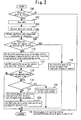
- FIG. 2 is a flowchart illustrating a control routine that the ECU 50 executes to realize the catalyst warm-up control in Embodiment 1 of the present invention. It is assumed that the present routine is started when the internal combustion engine 10 is started and is repeatedly executed for each predetermined control period.
- the ECU 50 determines whether or not there is a catalyst warm-up request to warm up the catalyst 38 (step 100). Specifically, the ECU 50 can determine whether or not the internal combustion engine 10 is in an unwarmed state after a cold startup, based on whether or not the engine cooling water temperature is equal to or less than a predetermined value. In the present step 100, if the internal combustion engine 10 is in an unwarmed state, the ECU 50 determines that there is a catalyst warm-up request if a predetermined catalyst warm-up completion condition is not established.
- Whether or not the catalyst warm-up completion condition is established can be determined, for example, on the basis of whether or not an integrated value of the intake air amount after starting the internal combustion engine 10 has reached a predetermined value (value that is previously set based on experimentation and the like) for determining whether or not the catalyst is warmed up.
- a predetermined value value that is previously set based on experimentation and the like
- step 100 if it is determined that there is a catalyst warm-up request, the processing in steps 102 and 104 are executed in order.
- step 102 the WGV 42 is opened to accelerate warm-up of the catalyst 38.
- the degree of opening of the WGV in this case is obtained by opening the WGV to a predetermined degree of opening relative to a degree of opening of the WGV under the same operating state (defined by the intake air amount and the engine speed) in a case where the catalyst warm-up control is not performed.
- This kind of adjustment of the degree of opening of the WGV includes a form in which the WGV 42 is opened to a predetermined degree of opening from a fully closed state, and a form in which the degree of opening of the WGV 42 that is already open is further increased by a predetermined degree of opening.
- step 104 the ignition timing is retarded in order to accelerate warm-up of the catalyst 38.
- the ignition timing in this case is retarded by a predetermined amount relative to the basic ignition timing under the same operating state in which the catalyst warm-up control is not performed.
- the retard amount of the ignition timing in this case is a value that differs according to the operating state (for example, according to whether the internal combustion engine 10 is in an idling state or is generating a torque to cause the vehicle to run).
- a throttle upstream pressure and a throttle downstream pressure are detected using the throttle upstream pressure sensor 31 and the throttle downstream pressure sensor 32 described above (step 106).
- the ECU 50 determines whether or not it is possible to secure the current required intake air amount by adjustment of the throttle valve 30 (step 108). Specifically, the ECU 50 determines whether or not the differential pressure between the throttle upstream pressure and the throttle downstream pressure acquired in the aforementioned step 106 is not equal to or less than a predetermined value. In a state in which the differential pressure between the throttle upstream pressure and the throttle downstream pressure is equal to or less than (almost equal to) the predetermined value, adjustment of the intake air amount by the throttle valve 30 is difficult. In other words, in this state, the sensitivity of control of the intake air amount by the throttle valve 30 decreases.
- the predetermined value of the differential pressure in the present step 108 is a value that is previously set as a threshold value for determining whether the control sensitivity with respect to the control of the intake air amount by the throttle valve 30 is in a high state or in a low state.
- step 110 If the result determined in the aforementioned step 108 is affirmative, that is, if it can be determined that the control sensitivity with respect to the control of the intake air amount by the throttle valve 30 is in a high state because the aforementioned differential pressure is not equal to or less than the aforementioned predetermined value, the processing in step 110 is executed.
- the degree of opening of the throttle is set to a value for ensuring that the current required intake air amount is obtained in step 110 upon receiving this kind of request, under circumstances in which control of the degree of opening of the WGV and control of the ignition timing have been performed in steps 102 and 104.
- step 112 the degree of opening of the throttle is set to a degree of opening for when the aforementioned differential pressure (difference between the intake pressures before and after the throttle valve 30) is less than or equal to the aforementioned predetermined value.
- the degree of opening of the WGV is set to a degree of opening at which the current required intake air amount is obtained under the degree of opening of the throttle that was set in the aforementioned step 112 (step 114).
- the relation between an amount of change in the degree of opening of the WGV and an amount of change in a supercharging pressure can be acquired, and an amount of change of the intake air amount can be acquired based on the amount of change in the supercharging pressure. Therefore, based on the relations in these maps, the degree of opening of the WGV that is required to ensure that a required intake air amount is obtained can be calculated.
- the ECU 50 determines whether or not the degree of opening of the WGV was changed toward the closed side by the processing in the aforementioned step 114 (step 116). If the result determined in the present step 116 is affirmative, the ECU 50 then determines whether or not retard of the ignition timing by a value that is equal to or greater than a predetermined value is possible, in other words, the ECU 50 determines whether or not a limit value of the ignition timing for which combustion is stable has not been reached (step 118).
- step 120 the retard amount of the ignition timing is increased (step 120).
- the WGV 42 is closed (when the degree of opening of the WGV is reduced)
- the amount of exhaust energy that is introduced to the catalyst 38 on the downstream side decreases. Consequently, in the present step 120, the retard amount of the ignition timing is increased to compensate for the amount of decrease in the energy introduced to the catalyst 38 due to the WGV 42 being controlled toward the closed side.
- the retard amount of the ignition timing is determined based on the relation with the degree of opening of the WGV that was set in the aforementioned step 114, so as to become a value that satisfies the relation in the following equation (1) (in the fast idling state, a value that simultaneously satisfies the relation in equation (2) in addition to equation (1)).
- ⁇ Ga1 represents the amount of an increase in the intake air amount that is produced as the result of closing the WGV 42 to the degree of opening set in the aforementioned step 114.
- ⁇ Qsa represents the amount of an increase in the energy per unit intake air amount when the retard amount of the ignition timing is increased to become the value set in the present step 120.
- ⁇ Qc1 represents an amount by which the energy introduced to the catalyst 38 decreases as a result of closing the WGV 42 to the degree of opening set in the aforementioned step 114.
- ⁇ Ga2 represents an intake air increase amount that is required to maintain a predetermined fast idling speed in a state in which the retard amount of the ignition timing is increased so as to become the value set in the present step 120.
- ⁇ Ga1, ⁇ Qsa, ⁇ Qc1 and ⁇ Ga2 can be respectively calculated, for example, by the following methods. That is, with respect to calculation of ⁇ Ga1, a relation (for example, a map) between an amount of change in the degree of opening of the WGV and an amount of change in the supercharging pressure accompanying the relevant change in the degree of opening of the WGV is previously determined by experimentation or the like and stored in the ECU 50. Based on such a relation, the ECU 50 calculates an amount of change in the supercharging pressure with respect to the amount of change in the degree of opening of the WGV that changes from the current degree of opening of the WGV to the value set in the aforementioned step 114. The ECU 50 then calculates the intake air increase amount ⁇ Ga1 based on the calculated amount of change in the supercharging pressure.
- a relation for example, a map
- ⁇ Qsa a relation (for example, a map) between an amount of change toward the retard side of the ignition timing and an amount of change ⁇ T in the exhaust gas temperature accompanying retard of the ignition timing by the amount of change is previously determined by experimentation or the like and stored in the ECU 50.
- the value of ⁇ Qsa can be calculated by multiplying a value of the specific heat c of exhaust gas per unit mass by an amount of change ⁇ T in the exhaust gas temperature that is calculated utilizing the aforementioned relation.
- ⁇ Qc1 a relation (for example, a map) between an amount of change in the degree of opening of the WGV and an amount of decrease in an energy amount that is introduced to the catalyst 38 accompanying the change in the degree of opening of the WGV is previously determined by experimentation or the like and stored in the ECU 50.
- the value of ⁇ Qc1 can be calculated by utilizing the aforementioned relation.
- ⁇ Ga2 a relation (for example, a map) between an amount of change toward the retard side of the ignition timing and an intake air increase amount that is required to maintain a predetermined fast idling speed in a state in which the ignition timing has been retarded by the amount of change is previously determined by experimentation or the like and stored in the ECU 50.
- the value of ⁇ Ga2 can be calculated utilizing the aforementioned relation.
- step 118 determines whether a limit value of the ignition timing from the viewpoint of suppressing combustion deterioration is reached.
- the retard amount of the ignition timing for the current processing is set to the limit value at which combustion is stable (step 122).
- a limit value of a retard amount of the ignition timing of this kind in relation to the operating state of the internal combustion engine 10 is stored as a map in the ECU 50.
- ⁇ Ga3 represents an amount of increase in the intake air amount in a case where the degree of opening of the WGV is closed so as to become a value set in the present step 124.
- Qsa represents an energy amount per unit intake air amount at the retard limit amount of the ignition timing that was set in the aforementioned step 122.
- ⁇ Qc2 represents an amount by which the energy introduced to the catalyst 38 decreases in a case where the degree of opening of the WGV is closed so as to become the value set in the present step 124.
- ⁇ Ga3 can be calculated by the above described method for ⁇ Ga1.
- Qsa can be calculated, for example, based on a map in which the relation between the value of Qsa and a retard limit amount of the ignition timing is previously determined.
- ⁇ Qc2 can be calculated, for example, by the above described method for ⁇ Qc1. In a case where the processing in the present step 124 is executed, the degree of opening of the WGV that is set in the present step 124 is used instead of the degree of opening of the WGV that was set in the aforementioned step 114.
- the degree of opening of the throttle is fixed at the value in this state, and the intake air amount is adjusted by adjusting the degree of opening of the WGV. Further, in this case, the retard amount of the ignition timing is increased to compensate for the amount of decrease in energy introduced to the catalyst 38 accompanying closing of the WGV 42.
- an energy amount introduced to the catalyst 38 can be secured at a level that is equal to a level in a flatland area, while ensuring the controllability of the intake air amount so that the required intake air amount is obtained. More specifically, if the case is one in which the vehicle is in a fast idling state after a cold startup, in a highland area also, an energy amount introduced to the catalyst 38 can be secured at a level that is equal to a level in a flatland area while maintaining a predetermined fast idling speed. As described above, according to the catalyst warm-up control of the present embodiment, warm-up performance with respect to the catalyst 38 can be favorably secured regardless of whether the atmospheric pressure is high or low.
- the degree of opening of the WGV and the retard amount of the ignition timing are set so as to satisfy the relation in the above equation (1) (the above equations (1) and (2) in the case of the fast idling state).
- the degree of opening of the WGV and the retard amount of the ignition timing are set taking into consideration the relation among: the intake air increase amount ⁇ Ga1 that is generated by closing the WGV 42; the amount of increase in energy per unit intake air amount ⁇ Qsa that is generated as a result of increasing the retard amount of the ignition timing; and the amount of decrease ⁇ Qc1 in the energy introduced to the catalyst as a result of closing the WGV 42.
- the degree of opening of the WGV and the retard amount of the ignition timing are set by taking into consideration the relation between the aforementioned ⁇ Ga1 and the intake air increase amount ⁇ Ga2 that is required to maintain a predetermined fast idling speed in a state in which the retard amount of the ignition timing is increased.
- the degree of opening of the WGV is set so as to satisfy the relation of the above described equation (3) in a state in which the ignition timing is fixed at the retard limit amount.
- the degree of opening of the WGV is set taking into consideration the relation among: the intake air increase amount ⁇ Ga3 that is generated by closing the WGV 42; the energy increase amount Qsa per unit intake air amount at the retard limit amount of the ignition timing that is set; and the amount of decrease ⁇ Qc2 in the energy introduced to the catalyst as a result of closing the WGV 42.
- the amount of energy introduced to the catalyst 38 can be favorably secured without loss of the combustion stability.
- the degree of opening of the WGV is set so as to satisfy the relation of the equation (3) in a state in which the ignition timing is fixed at the retard limit amount.
- a method for setting a suitable degree of opening of the WGV performed in this case is not limited to the above described method, and for example the setting method may be a method described hereunder.
- ⁇ Ga4 represents an amount by which the intake air amount decreases when the WGV is opened so as to have a degree of opening of a value that is set in this case.
- Qsa is the value that is described above.
- ⁇ Qc3 represents an amount by which the energy introduced to the catalyst 38 increases when the WGV is opened so as to have a degree of opening of the value that is set in this case.
- ⁇ Ga4 can be calculated by a similar method as the method described above with respect to ⁇ Ga1.
- ⁇ Qc3 can be calculated, for example, by a similar method as the method described above with respect to ⁇ Qc1.
- the amount of energy introduced to the catalyst 38 can be favorably secured without loss of the combustion stability.
- the intake air amount decreases when the WGV 42 is opened, although the fast idling speed decreases if the operating state is the fast idling state, the exhaust gas amount that is discharged from inside each cylinder decreases. Consequently, exhaust emissions released during warm-up of the catalyst 38 can be reduced. Accordingly, when compensating for a decrease in the amount of energy introduced to the catalyst 38 by retarding the ignition timing, it is possible to suppress a deterioration in the exhaust emission performance during warm-up due to an insufficient retard amount of the ignition timing.
- the "catalyst warm-up execution means" according to the aforementioned one aspect of the present invention is realized by the ECU 50 executing the aforementioned processing of steps 102 and 104;
- the "first intake air amount control means” according to the aforementioned one aspect of the present invention is realized by the ECU 50 executing the aforementioned processing of 110 in a case where the result of the determination in step 108 is affirmative;
- the "second intake air amount control means” according to the aforementioned one aspect of the present invention is realized by the ECU 50 executing the aforementioned processing of step 114 in a case where the result of the determination in step 108 is negative;
- the "ignition timing control means" according to the aforementioned one aspect of the present invention is realized by the ECU 50 executing the aforementioned processing of step 120 in a case where the results of the determinations in steps 116 and 118 are affirmative.
- the system of the present embodiment can be realized by using the hardware configuration illustrated in Figure 1 and causing the ECU 50 to execute the routine shown in Figure 3 , described later, instead of the routine shown in Figure 2 .
- Embodiment 1 a configuration is adopted in which, in a case where the sensitivity of control of the intake air amount by the throttle valve 30 is low when a catalyst warm-up request was issued, the intake air amount is adjusted by adjusting the degree of opening of the WGV 42 while the degree of opening of the throttle valve is kept constant.
- a configuration is adopted in which, in a case where the sensitivity of control of the intake air amount by the throttle valve 30 is in a low state when a catalyst warm-up request was issued, the degree of opening of the throttle valve is fixed at the degree of opening in this state and the WGV 42 is fully closed.
- adjustment of the degree of opening of the ABV 26 is utilized to adjust the intake air amount so that the required intake air amount is obtained.
- a retard amount of the ignition timing is increased to compensate for the amount by which the energy introduced to the catalyst 38 decreases due to the WGV 42 being fully closed.
- the degree of opening of the ABV 26 is set to a degree of opening on an open side while fixing the retard amount of the ignition timing.
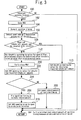
- FIG 3 is a flowchart illustrating a control routine that the ECU 50 executes to realize catalyst warm-up control according to Embodiment 2 of the present invention.
- steps that are the same as steps shown in Figure 2 according to Embodiment 1 are denoted by the same reference numerals, and a description of those steps is omitted or simplified.
- the degree of opening of the throttle valve is set to a degree of opening that is used in a case where the above described differential pressure (difference between the intake pressures before and after the throttle valve 30) is less than or equal to a predetermined value in the aforementioned step 108.
- the degree of opening of the WGV is set to a fully closed state (step 200).
- the ABV degree of opening is set to a degree of opening at which the current required intake air amount is obtained under a condition of the degree of opening of the throttle valve and degree of opening of the WGV that were set in the aforementioned steps 112 and 200 (step 202).
- the ABV 26 is opened in a state in which supercharging is being performed, a part of the intake air flowing through a section on the downstream side of the compressor 22a is returned to the upstream side of the compressor 22a through the intake bypass passage 24. As a result, the supercharging pressure decreases.
- the intake air amount can be reduced since the supercharging pressure decreases, and conversely, by adjusting the ABV degree of opening toward a degree of opening on the closed side, the intake air amount can be increased since the supercharging pressure rises.
- maps not illustrated in the drawings
- the relation between an amount of change in the ABV degree of opening and an amount of change in a supercharging pressure can be acquired, and an amount of change of the intake air amount can be acquired based on the amount of change in the supercharging pressure. Therefore, based on the relations in these maps, the ABV degree of opening that is required to ensure that the required intake air amount is obtained can be calculated.
- the ECU 50 determines whether or not it is predicted that the retard amount of the ignition timing is equal to or greater than a predetermined value (step 204).
- a predetermined value a predetermined value
- the retard amount of the ignition timing is gradually (by a predetermined amount at a time) increased by the processing in step 206, described later, to thereby compensate for the amount by which the energy introduced to the catalyst 38 decreases due to the degree of opening of the WGV being set to the fully closed state.
- a limit value of the retard amount of the ignition timing from the viewpoint of suppressing combustion deterioration is used. That is, in the present step 204, it is determined whether or not the retard amount of the ignition timing will reach the retard limit amount from the viewpoint of suppressing combustion deterioration if retard of the ignition timing by the predetermined amount is further performed for the above described purpose.
- the ignition timing is retarded by the predetermined amount (step 206).
- the final target value of the retard amount of the ignition timing with respect to the processing in the present step 206 is a value in accordance with the state of the WGV 42. Specifically, in the present embodiment, a retard amount of the ignition timing that is necessary to compensate for the amount of a decrease in the energy introduced to the catalyst 38 due to fully closing the WGV 42 in the aforementioned step 200 corresponds to the final target value.
- step 204 determines whether the retard limit amount will be reached if retard of the ignition timing by the predetermined amount is performed this time. If the result of the determination in the aforementioned step 204 is affirmative, that is, if it can be determined that the retard limit amount will be reached if retard of the ignition timing by the predetermined amount is performed this time, the ignition timing is fixed at the existing retard amount (step 208). Thereafter, the ABV degree of opening is set so as to open to a predetermined degree of opening (step 210).
- the ignition timing is fixed at the retard amount at the time of the aforementioned prediction, and thereafter the ABV 26 is opened. If it is assumed for instance that a sufficient retard amount of the ignition timing was not secured when the WGV 42 was closed (according to the present embodiment, was fully closed) as described above, there is a concern that the warm-up performance of the catalyst 38 will decline and the purification performance of the catalyst 38 will decrease.
- control of the ABV 26 is executed after predicting in advance arrival at the retard limit amount of the ignition timing from the viewpoint of suppressing combustion deterioration. It is thereby possible to suppress a deterioration in the exhaust emission performance during warm-up due to an insufficient retard amount of the ignition timing, while more reliably avoiding a deterioration in combustion that is caused by increasing the retard amount of the ignition timing.
- a configuration may also be adopted in which, in a case where the sensitivity of control of the intake air amount by the throttle valve 30 is in a low state, the WGV 42 is controlled to fully close.
- the degree of opening of the WGV that is controlled in this case is not necessarily limited to a fully closed state as long as the degree of opening of the WGV is a degree of opening on the closed side and, for example, may be a predetermined degree of opening in the vicinity of a fully closed state.
- the "catalyst warm-up execution means" according to the aforementioned another aspect of the present invention is realized by the ECU 50 executing the aforementioned processing of steps 102 and 104;
- the "first intake air amount control means” according to the aforementioned another aspect of the present invention is realized by the ECU 50 executing the aforementioned processing of step 110 in a case where the result of the determination in the aforementioned step 108 is affirmative;
- the "second intake air amount control means” according to the another aspect of the present invention is realized by the ECU 50 executing the aforementioned processing of steps 200 and 202 in a case where the result of the determination in the aforementioned step 108 is negative;
- the "ignition timing control means" according to the aforementioned another aspect of the present invention is realized by the ECU 50 executing the aforementioned processing of step 206 in a case where the result of the determination in the aforementioned step 204 is negative.
- the "air bypass valve control means" of the aforementioned another aspect of the present invention is realized by the ECU 50 executing the aforementioned processing of step 210 in a case where the result of the determination in the aforementioned step 204 is affirmative.
- a system of the present embodiment can be realized by using the hardware configuration illustrated in Figure 1 and causing the ECU 50 to execute the routine shown in Figure 4 , described later, instead of the routine shown in Figure 2 .
- Figure 4 is a flowchart illustrating a control routine that the ECU 50 executes in order to realize catalyst warm-up control according to Embodiment 3 of the present invention.
- steps that are the same as steps shown in Figures 2 and 3 according to Embodiments 1 and 2 are denoted by the same reference numerals, and a description of those steps is omitted or simplified.
- the processing of the present routine is processing that combines the routine shown in Figure 2 and the routine shown in Figure 3 . That is, processing that is executed when the sensitivity of control of the intake air amount by the throttle valve 30 is in a high state when a catalyst warm-up request is issued is the same as in the routines shown in Figures 2 and 3 . In contrast, in a case where the sensitivity of control of the intake air amount by the throttle valve 30 is in a low state when a catalyst warm-up request is issued, similarly to the routine shown in Figure 2 , the intake air amount is adjusted by adjustment of the degree of opening of the WGV 42 while the degree of opening of the throttle valve is kept constant.
- the retard amount of the ignition timing is increased (step 120).
- the degree of opening of the ABV 26 is set to a degree of opening on the open side by the processing in the aforementioned step 210.
- the warm-up performance with respect to the catalyst 38 can also be favorably secured by the catalyst warm-up control of the present embodiment that is realized by the routine shown in Figure 4 , regardless of whether the atmospheric pressure is high or low. Further, by means of the control of the ABV 26 in the present catalyst warm-up control, when retard of the ignition timing is utilized to compensate for an amount by which the energy introduced to the catalyst 38 decreases due to closing of the WGV 42, a deterioration in the exhaust emission performance that is caused by an insufficient retard amount of the ignition timing can be suppressed.
- the "air bypass valve control means" according to the aforementioned one aspect of the present invention is realized by the ECU 50 executing the aforementioned processing of step 210 in a case where the result of the determination in the aforementioned step 204 is affirmative.
- Embodiments 1 to 3 that are described above, a configuration is adopted so as to determine whether the sensitivity of control of the intake air amount by the throttle valve 30 is in a high state or a low state based on whether or not the differential pressure between the throttle upstream pressure and the throttle downstream pressure is not less than or equal to a predetermined value.
- the aforementioned determination as to whether the control sensitivity is high or low is not limited to the aforementioned method. That is, for example, a configuration may also be adopted which further includes an atmospheric pressure sensor, and in which the aforementioned determination as to whether the control sensitivity is high or low is made in accordance with an atmospheric pressure detected by the atmospheric pressure sensor.
Abstract
Description
- The present invention relates to a control apparatus for an internal combustion engine, and more particularly to a control apparatus for a supercharged internal combustion engine that includes a turbo-supercharger and a waste gate valve that opens and closes an exhaust bypass passage that bypasses a turbine of the turbo-supercharger.
- A control apparatus for an internal combustion engine which includes a turbo-supercharger and a waste gate valve that opens and closes an exhaust bypass passage that bypasses a turbine has already been disclosed in, for example,
Patent Literature 1. According to the conventional control apparatus, a configuration is adopted so as to perform the following control to warm up an exhaust gas purifying catalyst that is disposed on the downstream side of the turbine after a cold startup. That is, when the internal combustion engine is in an idling state after a cold startup, the aforementioned control apparatus is configured so as to execute catalyst warm-up control (specifically, corresponds to "upstream catalyst warm-up process" in Patent Literature 1) that opens the waste gate valve and retards the ignition timing. - Meanwhile, the atmospheric pressure is low in a highland area. If the air density decreases accompanying a decrease in the atmospheric pressure, the torque that is generated by an internal combustion engine decreases. Consequently, in a highland area, it is necessary to enlarge the degree of opening of a throttle valve in order to secure an intake air amount (required intake air amount) that is required to maintain an idling speed during execution of the above described catalyst warm-up control. Consequently, a difference between the intake pressures before and after the throttle valve decreases. For this reason, in a highland area, in some cases it is difficult to perform adjustment of the aforementioned required intake air amount using the throttle valve while catalyst warm-up control is being executed.
- Further, since the exhaust gas temperature rises when the ignition timing is retarded, the amount of exhaust energy that is introduced into the exhaust gas purifying catalyst can be increased. However, retarding the ignition timing leads to a decrease in the torque of the internal combustion engine. Accordingly, in a highland area, in a case where maintaining the idling speed is prioritized when it has become difficult to secure the required intake air amount using the throttle valve during execution of catalyst warm-up control, it is difficult to sufficiently retard the ignition timing. Consequently, it is difficult to maintain the amount of energy that is introduced to the exhaust gas purifying catalyst at a high level. Thus, with respect to the catalyst warm-up control disclosed in the
aforementioned Patent Literature 1, there is a concern that in a highland area where the atmospheric pressure is low, a situation may arise in which an exhaust gas purifying catalyst cannot be warmed up sufficiently. - Including the above described document, the applicant is aware of the following documents as related art of the present invention.
-
- Patent Document 1: Japanese Laid-open Patent Application Publication No.
2006-322427 - Patent Document 2: Japanese Laid-open Patent Application Publication No.
2004-124745 - Patent Document 3: Japanese Laid-open Patent Application Publication No.
2006-152821 - Patent Document 4: Japanese Laid-open Patent Application Publication No.
2002-213247 - The present invention has been conceived to solve the above described problem, and an object of the present invention is to provide a control apparatus for an internal combustion engine that, in a case where the internal combustion engine includes a turbo-supercharger and a waste gate valve that opens and closes an exhaust bypass passage that bypasses a turbine of the turbo-supercharger, is configured to be capable of favorably securing warm-up performance with respect to an exhaust gas purifying catalyst that is disposed on the downstream side of the turbine regardless of whether the atmospheric pressure is high or low.
- One aspect of the present invention is a control apparatus for an internal combustion engine having a turbo-supercharger and an exhaust gas purifying catalyst that is disposed in an exhaust passage on the downstream side of a turbine of the turbo-supercharger; the control apparatus including: a throttle valve, an ignition device, an exhaust bypass passage, a waste gate valve, catalyst warm-up execution means, first intake air amount control means, second intake air amount control means, and ignition timing control means.
- The throttle valve adjusts an intake air amount that is drawn into the internal combustion engine. The ignition device is included for igniting an air-fuel mixture in a cylinder of the internal combustion engine. The exhaust bypass passage branches from the exhaust passage on the upstream side of the turbine, and merges again with the exhaust passage at a location between the turbine and the exhaust gas purifying catalyst. The waste gate valve is capable of opening and closing the exhaust bypass passage. The catalyst warm-up execution means executes catalyst warm-up control that opens the waste gate valve and retards an ignition timing when there is a catalyst warm-up request to warm up the exhaust gas purifying catalyst. In a case where a control sensitivity with respect to control of an intake air amount by the throttle valve is high, the first intake air amount control means performs first intake air amount control that controls the intake air amount using the throttle valve so that a required intake air amount is obtained during execution of the catalyst warm-up control. In a case where the control sensitivity is low, the second intake air amount control means performs second intake air amount control that controls the intake air amount using the waste gate valve so that the required intake air amount is obtained during execution of the catalyst warm-up control. The ignition timing control means increases a retard amount of the ignition timing when a degree of opening of the waste gate valve is controlled toward the closed side during execution of the second intake air amount control.
- According to the one aspect of the present invention, a configuration is adopted so as to appropriately use two kinds of intake air amount control in accordance with whether the control sensitivity with respect to control of the intake air amount by the throttle valve is high or low. It is thus possible to control the intake air amount utilizing the waste gate valve even when the aforementioned control sensitivity is low. Further, the retard amount of the ignition timing is increased when the degree of opening of the waste gate valve during execution of the second intake air amount control is controlled toward the closed side. It is thus possible to compensate for a drop in the energy introduced to the exhaust gas purifying catalyst that accompanies closing of the waste gate valve. Consequently, according to the present invention, warm-up performance with respect to the exhaust gas purifying catalyst that is disposed on the downstream side of the turbine can be favorably secured regardless of whether the atmospheric pressure is high or low.
- The one aspect of the present invention may further include an intake bypass passage that branches from an intake passage on the upstream side of a compressor of the turbo-supercharger, and merges again with the intake passage at a location between the compressor and the throttle valve. The one aspect may also include an air bypass valve that is capable of opening and closing the intake bypass passage. In addition, the one aspect may further include air bypass valve control means for increasing a degree of opening of the air bypass valve in a case where it is predicted that an amount of retard of the ignition timing by the ignition timing control means will be equal to or greater than a predetermined value.
- An exhaust gas amount that is discharged from inside a cylinder decreases when the air bypass valve is opened. Therefore, exhaust emissions that are released during warm-up of the exhaust gas purifying catalyst can be reduced. Accordingly, when compensating for a drop in energy introduced to the exhaust gas purifying catalyst that is caused by retard of the ignition timing, a deterioration in the exhaust emission performance during warm-up due to an insufficient retard amount of the ignition timing can be suppressed while also avoiding a deterioration in combustion that is caused by an increase in the retard amount of the ignition timing.
- The catalyst warm-up execution means according to the one aspect of the present invention may execute the catalyst warm-up control in a fast idling state after a cold startup of the internal combustion engine. The first intake air amount control means may, in a case where the control sensitivity is high, control the throttle valve so that the required intake air amount that is necessary for maintaining an engine speed at a predetermined speed at the time of the fast idling is obtained. Further, the second intake air amount control means may, in a case where the control sensitivity is low, control the waste gate valve so that the required intake air amount that is necessary for maintaining the engine speed at the predetermined speed at the time of the fast idling is obtained.
- Thus, in a fast idling state after a cold startup, warm-up performance with respect to the exhaust gas purifying catalyst that is disposed on the downstream side of the turbine can be favorably secured regardless of whether the atmospheric pressure is high or low.
- Another aspect of the present invention is a control apparatus for an internal combustion engine having a turbo-supercharger and an exhaust gas purifying catalyst that is disposed in an exhaust passage on the downstream side of a turbine of the turbo-supercharger; the control apparatus including: a throttle valve, an ignition device, an exhaust bypass passage, a waste gate valve, an intake bypass passage, an air bypass valve, catalyst warm-up execution means, first intake air amount control means, second intake air amount control means, and ignition timing control means.
- The throttle valve adjusts an intake air amount that is drawn into the internal combustion engine. The ignition device is included for igniting an air-fuel mixture in a cylinder of the internal combustion engine. The exhaust bypass passage branches from the exhaust passage on the upstream side of the turbine, and merges again with the exhaust passage at a location between the turbine and the exhaust gas purifying catalyst. The waste gate valve is capable of opening and closing the exhaust bypass passage. The intake bypass passage branches from an intake passage on the upstream side of a compressor of the turbo-supercharger, and merges again with the intake passage at a location between the compressor and the throttle valve. The air bypass valve is capable of opening and closing the intake bypass passage. The catalyst warm-up execution means executes catalyst warm-up control that opens the waste gate valve and retards an ignition timing when there is a catalyst warm-up request to warm-up the exhaust gas purifying catalyst. In a case where a control sensitivity with respect to control of an intake air amount by the throttle valve is high, the first intake air amount control means performs first intake air amount control that controls the intake air amount using the throttle valve so that a required intake air amount is obtained during execution of the catalyst warm-up control. In a case where the control sensitivity is low, the second intake air amount control means performs second intake air amount control that controls a degree of opening of the waste gate valve toward the closed side and controls the intake air amount using the air bypass valve so that the required intake air amount is obtained during execution of the catalyst warm-up control. The ignition timing control means increases a retard amount of the ignition timing in accordance with the degree of opening of the waste gate valve that is controlled toward the closed side during execution of the second intake air amount control.
- According to the another aspect of the present invention, a configuration is adopted so as to appropriately use two kinds of intake air amount control in accordance with whether the control sensitivity with respect to control of the intake air amount by the throttle valve is high or low. Thus, even in a case where the aforementioned control sensitivity is low, the intake air amount can be controlled by closing the waste gate valve and utilizing the air bypass valve. Further, during execution of the second intake air amount control, the retard amount of the ignition timing is increased in accordance with the degree of opening of the waste gate valve that is controlled toward the closed side. It is thus possible to compensate for a drop in the energy introduced to the exhaust gas purifying catalyst that accompanies closing of the waste gate valve. Consequently, according to the present invention, warm-up performance with respect to the exhaust gas purifying catalyst that is disposed on the downstream side of the turbine can be favorably secured regardless of whether the atmospheric pressure is high or low.
- The another aspect of the present invention may further include air bypass valve control means for increasing a degree of opening of the air bypass valve in a case where it is predicted that an amount of retard of the ignition timing by the ignition timing control means will be equal to or greater than a predetermined value.
- The amount of exhaust gas that is discharged from inside a cylinder decreases when the air bypass valve is opened. Therefore, exhaust emissions that are released during warm-up of the exhaust gas purifying catalyst can be reduced. Accordingly, when compensating for a drop in energy introduced to the exhaust gas purifying catalyst that is caused by retard of the ignition timing, a deterioration in the exhaust emission performance during warm-up due to an insufficient retard amount of the ignition timing can be suppressed while also avoiding a deterioration in combustion that is caused by an increase in the retard amount of the ignition timing.
- The catalyst warm-up execution means according to the another aspect of the present invention may execute the catalyst warm-up control in a fast idling state after a cold startup of the internal combustion engine. The first intake air amount control means may, in a case where the control sensitivity is high, control the throttle valve so that the required intake air amount that is necessary for maintaining an engine speed at a predetermined speed at the time of the fast idling is obtained. Further, the second intake air amount control means may, in a case where the control sensitivity is low, control the air bypass valve so that the required intake air amount that is necessary for maintaining the engine speed at the predetermined speed at the time of the fast idling is obtained.
- Thus, in a fast idling state after a cold startup, warm-up performance with respect to the exhaust gas purifying catalyst that is disposed on the downstream side of the turbine can be favorably secured regardless of whether the atmospheric pressure is high or low.
-
-
Figure 1 is a schematic view for describing the system configuration of an internal combustion engine according toEmbodiment 1 of the present invention; -
Figure 2 is a flowchart of a routine that is executed inEmbodiment 1 of the present invention; -
Figure 3 is a flowchart of a routine that is executed in Embodiment 2 of the present invention; and -
Figure 4 is a flowchart of a routine that is executed in Embodiment 3 of the present invention. -
Figure 1 is a schematic view for describing the system configuration of aninternal combustion engine 10 according toEmbodiment 1 of the present invention. A system of the present embodiment includes a spark ignition-type internal combustion engine (as one example, a gasoline engine) 10. A combustion chamber 12 is formed inside each cylinder of theinternal combustion engine 10. Anintake passage 14 and anexhaust passage 16 communicate with the combustion chamber 12. - An
air cleaner 18 is installed in the vicinity of the inlet of theintake passage 14. Anair flow meter 20 that outputs a signal in accordance with a flow rate of air that is drawn into theintake passage 14 is provided in the vicinity of theair cleaner 18 on the downstream side thereof. Acompressor 22a of a turbo-supercharger 22 is arranged downstream of theair flow meter 20. Thecompressor 22a is integrally connected through a connecting shaft (not illustrated in the drawings) with aturbine 22b arranged in theexhaust passage 16. Anintake bypass passage 24 for bypassing thecompressor 22a is connected to theintake passage 14. An air bypass valve (ABV) 26 for controlling the flow rate of air that passes through theintake bypass passage 24 is arranged partway along theintake bypass passage 24. - An
intercooler 28 that cools compressed air is provided on the downstream side of thecompressor 22a. An electronically controlled throttle valve 30 is provided downstream of theintercooler 28. At a location in theintake passage 14 that is on the upstream side of the throttle valve 30 and on a downstream side of thecompressor 22a (and the intercooler 28), a throttle upstream pressure sensor 31 is installed that detects an intake pressure (throttle upstream pressure) at the aforementioned location. Further, at a location in theintake passage 14 that is on a downstream side of the throttle valve 30 (convergence portion (surge tank portion) of the intake manifold), a throttledownstream pressure sensor 32 is installed that detects an intake pressure (throttle downstream pressure) at the aforementioned location. - Each cylinder of the
internal combustion engine 10 is provided with afuel injection valve 34 for injecting fuel into the cylinder, and an ignition device 36 for igniting an air-fuel mixture. - An exhaust gas purifying catalyst (hereunder, referred to as simply "catalyst") 38 for purifying exhaust gas is arranged in the
exhaust passage 16 on a downstream side of theturbine 22b. Anexhaust bypass passage 40 is connected to theexhaust passage 16. Theexhaust bypass passage 40 is configured so as to branch from theexhaust passage 16 at a location that is further on the upstream side than theturbine 22b, and to merge again with theexhaust passage 16 at a location that is between theturbine 22b and thecatalyst 38. A waste gate valve (WGV) 42 that is capable of opening and closing theexhaust bypass passage 40 is provided partway along theexhaust bypass passage 40. In this case, it is assumed that theWGV 42 is configured to be adjustable to an arbitrary opening degree by means of an electric motor (not illustrated in the drawings). - An A/
F sensor 44 that produces a substantially linear output with respect to an air-to-fuel ratio of exhaust gas that flows into thecatalyst 38 is arranged in theexhaust passage 16 at a location that is on the upstream side of thecatalyst 38. On the downstream side of thecatalyst 38 in theexhaust passage 16 is arranged an O2 sensor 46 that generates a rich output when exhaust gas flowing thereto from thecatalyst 38 is rich relative to the theoretical air-to-fuel ratio, and generates a lean output when the exhaust gas is lean relative to the theoretical air-to-fuel ratio. Acrank angle sensor 48 for detecting the engine speed and the crank angle is also installed in theinternal combustion engine 10. - The system illustrated in
Figure 1 also includes an ECU (Electronic Control Unit) 50. In addition to theair flow meter 20, the throttle upstream pressure sensor 31, the throttledownstream pressure sensor 32, the A/F sensor 44, the O2 sensor 46, and thecrank angle sensor 48 that are described above, various sensors for detecting the operating state of theinternal combustion engine 10 such as awater temperature sensor 52 for detecting an engine cooling water temperature are connected to theECU 50. An accelerator position sensor 54 for detecting a depression amount of an accelerator pedal (accelerator position) of the vehicle in which theinternal combustion engine 10 is mounted is also connected to theECU 50. In addition, various actuators for controlling the operating state of theinternal combustion engine 10 such as theABV 26, the throttle valve 30, thefuel injection valve 34, the ignition device 36 and theWGV 42 that are described above are connected to theECU 50. TheECU 50 controls the operating state of theinternal combustion engine 10 by causing the various actuators to operate based on the outputs of the various sensors and predetermined programs. - In the
internal combustion engine 10 having the above described configuration, in a situation in which thecatalyst 38 has not reached a predetermined activated state, such as a situation at the time of a cold startup, catalyst warm-up control is executed to warm up thecatalyst 38 in order to quickly reach an activated state. The catalyst warm-up control of the present embodiment is basically control that opens theWGV 42 and retards the ignition timing. In comparison to a case where theWGV 42 is closed, when theWGV 42 is open the amount of exhaust energy that is recovered by theturbine 22b decreases, and consequently the amount of exhaust energy that is introduced to thecatalyst 38 on the downstream side can be increased. Further, the exhaust gas temperature increases when the ignition timing is retarded, and hence the amount of exhaust energy that is introduced to thecatalyst 38 on the downstream side can be increased. - Further, it is taken as a premise that, in a case where starting of the
internal combustion engine 10 was commenced in a cold state, to accelerate the warming up of theinternal combustion engine 10 including thecatalyst 38, theinternal combustion engine 10 is controlled in a fast idling state in which theinternal combustion engine 10 operates at a higher speed than in a normal idling state (hereunder, the engine speed in such a case is referred to as "fast idling speed"). The catalyst warm-up control of the present embodiment is mainly executed in the above described fast idling state. However, the present catalyst warm-up control is not only executed in the fast idling state, and the present catalyst warm-up control can also be executed in a state in which theinternal combustion engine 10 is operated at a requested load accompanying a request to start to move the vehicle that is made by the driver in the fast idling state. - During execution of the catalyst warm-up control, fundamentally, the intake air amount is controlled using the throttle valve 30 so that an intake air amount that is required by the internal combustion engine 10 (hereunder, referred to as "required intake air amount") is obtained. More specifically, when the
internal combustion engine 10 is in the fast idling state, the intake air amount is controlled using the throttle valve 30 so that an intake air amount (corresponds to the required intake air amount in this case) that is required to maintain a predetermined fast idling speed is obtained. According to the above described catalyst warm-up control, warm-up of thecatalyst 38 can be accelerated by intentionally increasing the amount of exhaust energy that is introduced to thecatalyst 38. - Meanwhile, the atmospheric pressure is lower in a highland area. When the air density decreases accompanying a drop in the atmospheric pressure, the torque that the
internal combustion engine 10 generates decreases. Consequently, in a highland area, it is required to increase the degree of opening of the throttle valve 30 in order to secure the required intake air amount during execution of the catalyst warm-up control (including a case where theinternal combustion engine 10 is in the fast idling state). Consequently, a difference between the intake pressures before and after the throttle valve 30 decreases. For such reasons, in a highland area, it is difficult in some cases to perform the above described adjustment of the required intake air amount using the throttle valve 30 while executing the catalyst warm-up control. - Further, in a case where the ignition timing is retarded, the amount of exhaust energy that is introduced to the
catalyst 38 can be increased since the exhaust gas temperature rises. However, retarding of the ignition timing leads to a decrease in the torque of theinternal combustion engine 10. Accordingly, in a highland area, when it has become difficult to secure the required intake air amount using the throttle valve 30 during execution of the catalyst warm-up control, in a case where securing the required torque of the internal combustion engine 10 (in a fast idling state, maintaining the fast idling speed) is prioritized, it is difficult to adequately retard the ignition timing. Consequently, it is difficult to maintain the amount of energy that is introduced to thecatalyst 38 at a high level. - Therefore, according to the present embodiment, to ensure that favorable warm-up performance can be secured with respect to the
catalyst 38 regardless of whether the atmospheric pressure is high or low (that is, whether the vehicle is in a flatland area or a highland area), the following control is performed as necessary in addition to the fundamental control in the catalyst warm-up control that is described above. - Specifically, in the case of performing the catalyst warm-up control, first the above described fundamental control is attempted (that is, control of the intake air amount using the throttle valve 30 so as to obtain the required intake air amount while opening the
WGV 42 and retarding the ignition timing). Subsequently, if a state is reached in which adjustment of the intake air amount by means of the throttle valve 30 is difficult (specifically, a state in which a difference between the intake pressures before and after the throttle valve 30 is less than or equal to a predetermined value) because the air density is low due to the influence of the atmospheric pressure, the degree of opening of the throttle is fixed at the degree of opening in this state. Furthermore, control of the intake air amount is performed by adjusting the degree of opening of theWGV 42 so that the required intake air amount is obtained. In addition, in this case, a retard amount of the ignition timing is increased to compensate for the amount of a decrease in the energy introduced to thecatalyst 38 that accompanies closing of theWGV 42. - Further, according to the catalyst warm-up control of the present embodiment, in a case where retard of the ignition timing is performed up to a point that deterioration of combustion due to retard of the ignition timing is assumed to occur while adjusting the intake air amount using the
WGV 42, the ignition timing is fixed at a retard amount that is a limit from the viewpoint of suppressing combustion deterioration, and the degree of opening of the WGV is set so as to satisfy the relation in equation (3) that is described below. -
Figure 2 is a flowchart illustrating a control routine that theECU 50 executes to realize the catalyst warm-up control inEmbodiment 1 of the present invention. It is assumed that the present routine is started when theinternal combustion engine 10 is started and is repeatedly executed for each predetermined control period. - According to the routine shown in
Figure 2 , first, theECU 50 determines whether or not there is a catalyst warm-up request to warm up the catalyst 38 (step 100). Specifically, theECU 50 can determine whether or not theinternal combustion engine 10 is in an unwarmed state after a cold startup, based on whether or not the engine cooling water temperature is equal to or less than a predetermined value. In thepresent step 100, if theinternal combustion engine 10 is in an unwarmed state, theECU 50 determines that there is a catalyst warm-up request if a predetermined catalyst warm-up completion condition is not established. Whether or not the catalyst warm-up completion condition is established can be determined, for example, on the basis of whether or not an integrated value of the intake air amount after starting theinternal combustion engine 10 has reached a predetermined value (value that is previously set based on experimentation and the like) for determining whether or not the catalyst is warmed up. - In the
aforementioned step 100, if it is determined that there is a catalyst warm-up request, the processing insteps step 102, theWGV 42 is opened to accelerate warm-up of thecatalyst 38. Specifically, the degree of opening of the WGV in this case is obtained by opening the WGV to a predetermined degree of opening relative to a degree of opening of the WGV under the same operating state (defined by the intake air amount and the engine speed) in a case where the catalyst warm-up control is not performed. This kind of adjustment of the degree of opening of the WGV includes a form in which theWGV 42 is opened to a predetermined degree of opening from a fully closed state, and a form in which the degree of opening of theWGV 42 that is already open is further increased by a predetermined degree of opening. - In
step 104, the ignition timing is retarded in order to accelerate warm-up of thecatalyst 38. Specifically, the ignition timing in this case is retarded by a predetermined amount relative to the basic ignition timing under the same operating state in which the catalyst warm-up control is not performed. Note that, the retard amount of the ignition timing in this case is a value that differs according to the operating state (for example, according to whether theinternal combustion engine 10 is in an idling state or is generating a torque to cause the vehicle to run). - Next, a throttle upstream pressure and a throttle downstream pressure are detected using the throttle upstream pressure sensor 31 and the throttle
downstream pressure sensor 32 described above (step 106). - Thereafter, the
ECU 50 determines whether or not it is possible to secure the current required intake air amount by adjustment of the throttle valve 30 (step 108). Specifically, theECU 50 determines whether or not the differential pressure between the throttle upstream pressure and the throttle downstream pressure acquired in theaforementioned step 106 is not equal to or less than a predetermined value. In a state in which the differential pressure between the throttle upstream pressure and the throttle downstream pressure is equal to or less than (almost equal to) the predetermined value, adjustment of the intake air amount by the throttle valve 30 is difficult. In other words, in this state, the sensitivity of control of the intake air amount by the throttle valve 30 decreases. The predetermined value of the differential pressure in thepresent step 108 is a value that is previously set as a threshold value for determining whether the control sensitivity with respect to the control of the intake air amount by the throttle valve 30 is in a high state or in a low state. - If the result determined in the
aforementioned step 108 is affirmative, that is, if it can be determined that the control sensitivity with respect to the control of the intake air amount by the throttle valve 30 is in a high state because the aforementioned differential pressure is not equal to or less than the aforementioned predetermined value, the processing instep 110 is executed. - Since the amount of exhaust energy that is supplied to the
turbine 22b decreases when theWGV 42 is opened (when the degree of opening of the WGV increases), the turbine speed decreases. Consequently, the throttle upstream pressure decreases under the same degree of throttle opening condition. Accordingly, it is necessary to increase the degree of opening of the throttle to maintain the same intake air amount in a case where theWGV 42 is opened (a case where the degree of opening of the WGV is increased). Further, if the ignition timing is retarded, the torque of theinternal combustion engine 10 decreases. Accordingly, a larger intake air amount is required to maintain the same level of torque as prior to retard of the ignition timing (if the state is the fast idling state, to maintain the same fast idling speed). Therefore, it is necessary to increase the intake air amount by enlarging the degree of opening of the throttle. The degree of opening of the throttle is set to a value for ensuring that the current required intake air amount is obtained instep 110 upon receiving this kind of request, under circumstances in which control of the degree of opening of the WGV and control of the ignition timing have been performed insteps - In contrast, if the result determined in the
aforementioned step 108 is negative, that is, when it can be determined that the sensitivity of control of the intake air amount by the throttle valve 30 is in a low state based on the fact that the aforementioned differential pressure is equal to or less than the aforementioned predetermined value, the processing fromstep 112 onward are executed in order. Instep 112, the degree of opening of the throttle is set to a degree of opening for when the aforementioned differential pressure (difference between the intake pressures before and after the throttle valve 30) is less than or equal to the aforementioned predetermined value. - Next, the degree of opening of the WGV is set to a degree of opening at which the current required intake air amount is obtained under the degree of opening of the throttle that was set in the aforementioned step 112 (step 114). Specifically, on the basis of maps (not illustrated in the drawings) that are based on the operating state which are included in the
ECU 50, the relation between an amount of change in the degree of opening of the WGV and an amount of change in a supercharging pressure can be acquired, and an amount of change of the intake air amount can be acquired based on the amount of change in the supercharging pressure. Therefore, based on the relations in these maps, the degree of opening of the WGV that is required to ensure that a required intake air amount is obtained can be calculated. Next, theECU 50 determines whether or not the degree of opening of the WGV was changed toward the closed side by the processing in the aforementioned step 114 (step 116). If the result determined in thepresent step 116 is affirmative, theECU 50 then determines whether or not retard of the ignition timing by a value that is equal to or greater than a predetermined value is possible, in other words, theECU 50 determines whether or not a limit value of the ignition timing for which combustion is stable has not been reached (step 118). - If the result determined in the
aforementioned step 118 is affirmative, the retard amount of the ignition timing is increased (step 120). When theWGV 42 is closed (when the degree of opening of the WGV is reduced), the amount of exhaust energy that is introduced to thecatalyst 38 on the downstream side decreases. Consequently, in thepresent step 120, the retard amount of the ignition timing is increased to compensate for the amount of decrease in the energy introduced to thecatalyst 38 due to theWGV 42 being controlled toward the closed side. - More specifically, in the
present step 120, the retard amount of the ignition timing is determined based on the relation with the degree of opening of the WGV that was set in theaforementioned step 114, so as to become a value that satisfies the relation in the following equation (1) (in the fast idling state, a value that simultaneously satisfies the relation in equation (2) in addition to equation (1)).

- Where, in the above equation (1), ΔGa1 represents the amount of an increase in the intake air amount that is produced as the result of closing the
WGV 42 to the degree of opening set in theaforementioned step 114. In addition, ΔQsa represents the amount of an increase in the energy per unit intake air amount when the retard amount of the ignition timing is increased to become the value set in thepresent step 120. Further, ΔQc1 represents an amount by which the energy introduced to thecatalyst 38 decreases as a result of closing theWGV 42 to the degree of opening set in theaforementioned step 114. In addition, in the above equation (2), ΔGa2 represents an intake air increase amount that is required to maintain a predetermined fast idling speed in a state in which the retard amount of the ignition timing is increased so as to become the value set in thepresent step 120. - These values ΔGa1, ΔQsa, ΔQc1 and ΔGa2 can be respectively calculated, for example, by the following methods. That is, with respect to calculation of ΔGa1, a relation (for example, a map) between an amount of change in the degree of opening of the WGV and an amount of change in the supercharging pressure accompanying the relevant change in the degree of opening of the WGV is previously determined by experimentation or the like and stored in the
ECU 50. Based on such a relation, theECU 50 calculates an amount of change in the supercharging pressure with respect to the amount of change in the degree of opening of the WGV that changes from the current degree of opening of the WGV to the value set in theaforementioned step 114. TheECU 50 then calculates the intake air increase amount ΔGa1 based on the calculated amount of change in the supercharging pressure. - With respect to calculation of ΔQsa, a relation (for example, a map) between an amount of change toward the retard side of the ignition timing and an amount of change ΔT in the exhaust gas temperature accompanying retard of the ignition timing by the amount of change is previously determined by experimentation or the like and stored in the
ECU 50. The value of ΔQsa can be calculated by multiplying a value of the specific heat c of exhaust gas per unit mass by an amount of change ΔT in the exhaust gas temperature that is calculated utilizing the aforementioned relation. Further, with respect to calculation of ΔQc1, a relation (for example, a map) between an amount of change in the degree of opening of the WGV and an amount of decrease in an energy amount that is introduced to thecatalyst 38 accompanying the change in the degree of opening of the WGV is previously determined by experimentation or the like and stored in theECU 50. The value of ΔQc1 can be calculated by utilizing the aforementioned relation. In addition, with respect to calculation of ΔGa2, a relation (for example, a map) between an amount of change toward the retard side of the ignition timing and an intake air increase amount that is required to maintain a predetermined fast idling speed in a state in which the ignition timing has been retarded by the amount of change is previously determined by experimentation or the like and stored in theECU 50. The value of ΔGa2 can be calculated utilizing the aforementioned relation. - In contrast, if the result determined in the
aforementioned step 118 is negative, that is, in a case where it is determined that a limit value of the ignition timing from the viewpoint of suppressing combustion deterioration is reached, the retard amount of the ignition timing for the current processing is set to the limit value at which combustion is stable (step 122). A limit value of a retard amount of the ignition timing of this kind in relation to the operating state of theinternal combustion engine 10 is stored as a map in theECU 50. - Next, a degree of opening of the WGV that satisfies the following condition is set (step 124). More specifically, in the
present step 124, a degree of opening of the WGV is determined in relation to the retard limit amount of the ignition timing that was set in theaforementioned step 122, so as to be a value that satisfies the relation in the following equation (3).
- Where, in the above equation (3), ΔGa3 represents an amount of increase in the intake air amount in a case where the degree of opening of the WGV is closed so as to become a value set in the
present step 124. In addition, Qsa represents an energy amount per unit intake air amount at the retard limit amount of the ignition timing that was set in theaforementioned step 122. Further, ΔQc2 represents an amount by which the energy introduced to thecatalyst 38 decreases in a case where the degree of opening of the WGV is closed so as to become the value set in thepresent step 124. - For example, ΔGa3 can be calculated by the above described method for ΔGa1. Further, Qsa can be calculated, for example, based on a map in which the relation between the value of Qsa and a retard limit amount of the ignition timing is previously determined. In addition, ΔQc2 can be calculated, for example, by the above described method for ΔQc1. In a case where the processing in the
present step 124 is executed, the degree of opening of the WGV that is set in thepresent step 124 is used instead of the degree of opening of the WGV that was set in theaforementioned step 114. - According to the routine illustrated in
Figure 2 that is described above, in a case where the sensitivity of control of the intake air amount by the throttle valve 30 is in a high state when a catalyst warm-up request was issued (a case where the vehicle is in a flatland area in which the atmospheric pressure is comparatively high), the ignition timing is retarded accompanying opening of theWGV 42. Further, adjustment of the intake air amount in this case is performed using the throttle valve 30. On the other hand, in a case where the sensitivity of control of the intake air amount by the throttle valve 30 is in a low state when a catalyst warm-up request was issued (a case where the vehicle is in a highland area in which the atmospheric pressure is comparatively low), the degree of opening of the throttle is fixed at the value in this state, and the intake air amount is adjusted by adjusting the degree of opening of the WGV. Further, in this case, the retard amount of the ignition timing is increased to compensate for the amount of decrease in energy introduced to thecatalyst 38 accompanying closing of theWGV 42. - Thus, even in a highland area in which the atmospheric pressure is low, an energy amount introduced to the
catalyst 38 can be secured at a level that is equal to a level in a flatland area, while ensuring the controllability of the intake air amount so that the required intake air amount is obtained. More specifically, if the case is one in which the vehicle is in a fast idling state after a cold startup, in a highland area also, an energy amount introduced to thecatalyst 38 can be secured at a level that is equal to a level in a flatland area while maintaining a predetermined fast idling speed. As described above, according to the catalyst warm-up control of the present embodiment, warm-up performance with respect to thecatalyst 38 can be favorably secured regardless of whether the atmospheric pressure is high or low. - Further, according to the above described routine, in a case where the sensitivity of control of the intake air amount by the throttle valve 30 is in a low state when a catalyst warm-up request is issued, the degree of opening of the WGV and the retard amount of the ignition timing are set so as to satisfy the relation in the above equation (1) (the above equations (1) and (2) in the case of the fast idling state). That is, by utilizing the relation in the above described equation (1), the degree of opening of the WGV and the retard amount of the ignition timing are set taking into consideration the relation among: the intake air increase amount ΔGa1 that is generated by closing the
WGV 42; the amount of increase in energy per unit intake air amount ΔQsa that is generated as a result of increasing the retard amount of the ignition timing; and the amount of decrease ΔQc1 in the energy introduced to the catalyst as a result of closing theWGV 42. Further, in the case of the fast idling state, by also utilizing the equation (2) in addition to the equation (1), the degree of opening of the WGV and the retard amount of the ignition timing are set by taking into consideration the relation between the aforementioned ΔGa1 and the intake air increase amount ΔGa2 that is required to maintain a predetermined fast idling speed in a state in which the retard amount of the ignition timing is increased. Thus, regardless of whether the atmospheric pressure is high or low, the drivability of theinternal combustion engine 10 can be ensured while securing an equal amount of energy that is introduced to thecatalyst 38. - Furthermore, according to the above described routine, in a case where the ignition timing was retarded up to a point at which deterioration of combustion due to retard of the ignition timing is assumed to occur (a case where the result of the determination in the
aforementioned step 118 is negative), the degree of opening of the WGV is set so as to satisfy the relation of the above described equation (3) in a state in which the ignition timing is fixed at the retard limit amount. That is, by utilizing the relation in the equation (3), the degree of opening of the WGV is set taking into consideration the relation among: the intake air increase amount ΔGa3 that is generated by closing theWGV 42; the energy increase amount Qsa per unit intake air amount at the retard limit amount of the ignition timing that is set; and the amount of decrease ΔQc2 in the energy introduced to the catalyst as a result of closing theWGV 42. Thus, regardless of whether the atmospheric pressure is high or low, the amount of energy introduced to thecatalyst 38 can be favorably secured without loss of the combustion stability. - Incidentally, in the above described
Embodiment 1, in a case where the ignition timing was retarded up to a point at which deterioration of combustion due to retard of the ignition timing is assumed to occur (a case where the result of the determination in theaforementioned step 118 is negative), the degree of opening of the WGV is set so as to satisfy the relation of the equation (3) in a state in which the ignition timing is fixed at the retard limit amount. However, a method for setting a suitable degree of opening of the WGV performed in this case is not limited to the above described method, and for example the setting method may be a method described hereunder. - That is, a configuration may also be adopted in which, in a case where the ignition timing was retarded up to a point at which deterioration of combustion due to retard of the ignition timing is assumed to occur, adjustment of the intake air amount is performed while opening the degree of opening of the WGV in a state in which the ignition timing is fixed at the retard limit amount. More specifically, the degree of opening of the WGV may be determined in relation to the retard limit amount of the ignition timing that was set in the
aforementioned step 122, so as to be a value that satisfies the relation in the following equation (4).
- Where, in the above equation (4), ΔGa4 represents an amount by which the intake air amount decreases when the WGV is opened so as to have a degree of opening of a value that is set in this case. Qsa is the value that is described above. Further, ΔQc3 represents an amount by which the energy introduced to the
catalyst 38 increases when the WGV is opened so as to have a degree of opening of the value that is set in this case. For example, ΔGa4 can be calculated by a similar method as the method described above with respect to ΔGa1. Further, ΔQc3 can be calculated, for example, by a similar method as the method described above with respect to ΔQc1. - According to this method also, regardless of whether the atmospheric pressure is high or low, the amount of energy introduced to the
catalyst 38 can be favorably secured without loss of the combustion stability. Further, according to the present method, because the intake air amount decreases when theWGV 42 is opened, although the fast idling speed decreases if the operating state is the fast idling state, the exhaust gas amount that is discharged from inside each cylinder decreases. Consequently, exhaust emissions released during warm-up of thecatalyst 38 can be reduced. Accordingly, when compensating for a decrease in the amount of energy introduced to thecatalyst 38 by retarding the ignition timing, it is possible to suppress a deterioration in the exhaust emission performance during warm-up due to an insufficient retard amount of the ignition timing. - Note that, in the above described
Embodiment 1, the "catalyst warm-up execution means" according to the aforementioned one aspect of the present invention is realized by theECU 50 executing the aforementioned processing ofsteps ECU 50 executing the aforementioned processing of 110 in a case where the result of the determination instep 108 is affirmative; the "second intake air amount control means" according to the aforementioned one aspect of the present invention is realized by theECU 50 executing the aforementioned processing ofstep 114 in a case where the result of the determination instep 108 is negative; and the "ignition timing control means" according to the aforementioned one aspect of the present invention is realized by theECU 50 executing the aforementioned processing ofstep 120 in a case where the results of the determinations insteps - Next, Embodiment 2 of the present invention will be described referring to
Figure 3 . - The system of the present embodiment can be realized by using the hardware configuration illustrated in
Figure 1 and causing theECU 50 to execute the routine shown inFigure 3 , described later, instead of the routine shown inFigure 2 . - In the above described Embodiment 1 a configuration is adopted in which, in a case where the sensitivity of control of the intake air amount by the throttle valve 30 is low when a catalyst warm-up request was issued, the intake air amount is adjusted by adjusting the degree of opening of the
WGV 42 while the degree of opening of the throttle valve is kept constant. In contrast, according to the catalyst warm-up control of the present embodiment, a configuration is adopted in which, in a case where the sensitivity of control of the intake air amount by the throttle valve 30 is in a low state when a catalyst warm-up request was issued, the degree of opening of the throttle valve is fixed at the degree of opening in this state and theWGV 42 is fully closed. Furthermore, in this case, adjustment of the degree of opening of theABV 26 is utilized to adjust the intake air amount so that the required intake air amount is obtained. In addition, in this case also, a retard amount of the ignition timing is increased to compensate for the amount by which the energy introduced to thecatalyst 38 decreases due to theWGV 42 being fully closed. - Further, according to the catalyst warm-up control of the present embodiment, in a case where it is predicted that the retard amount of the ignition timing will become equal to or greater than a predetermined value during adjustment of the intake air amount using the
ABV 26, the degree of opening of theABV 26 is set to a degree of opening on an open side while fixing the retard amount of the ignition timing. -
Figure 3 is a flowchart illustrating a control routine that theECU 50 executes to realize catalyst warm-up control according to Embodiment 2 of the present invention. InFigure 3 , steps that are the same as steps shown inFigure 2 according toEmbodiment 1 are denoted by the same reference numerals, and a description of those steps is omitted or simplified. - In the routine illustrated in
Figure 3 , similarly to the routine illustrated in the above describedFigure 2 , if the result of the determination instep 108 is negative (that is, in a case where the sensitivity of control of the intake air amount by the throttle valve 30 is in a low state), the degree of opening of the throttle valve is set to a degree of opening that is used in a case where the above described differential pressure (difference between the intake pressures before and after the throttle valve 30) is less than or equal to a predetermined value in theaforementioned step 108. - Furthermore, in the routine illustrated in
Figure 3 , next, the degree of opening of the WGV is set to a fully closed state (step 200). Next, the ABV degree of opening is set to a degree of opening at which the current required intake air amount is obtained under a condition of the degree of opening of the throttle valve and degree of opening of the WGV that were set in theaforementioned steps 112 and 200 (step 202). When theABV 26 is opened in a state in which supercharging is being performed, a part of the intake air flowing through a section on the downstream side of thecompressor 22a is returned to the upstream side of thecompressor 22a through theintake bypass passage 24. As a result, the supercharging pressure decreases. Accordingly, by adjusting the ABV degree of opening toward a degree of opening on the open side, the intake air amount can be reduced since the supercharging pressure decreases, and conversely, by adjusting the ABV degree of opening toward a degree of opening on the closed side, the intake air amount can be increased since the supercharging pressure rises. Specifically, on the basis of maps (not illustrated in the drawings) based on the operating state which are included in theECU 50, the relation between an amount of change in the ABV degree of opening and an amount of change in a supercharging pressure can be acquired, and an amount of change of the intake air amount can be acquired based on the amount of change in the supercharging pressure. Therefore, based on the relations in these maps, the ABV degree of opening that is required to ensure that the required intake air amount is obtained can be calculated. - Next, the
ECU 50 determines whether or not it is predicted that the retard amount of the ignition timing is equal to or greater than a predetermined value (step 204). According to the catalyst warm-up control of the present embodiment, in a case where the degree of opening of the WGV was set to a fully closed state as in theaforementioned step 200 in a situation in which the sensitivity of control of the intake air amount by the throttle valve 30 is low, the retard amount of the ignition timing is gradually (by a predetermined amount at a time) increased by the processing instep 206, described later, to thereby compensate for the amount by which the energy introduced to thecatalyst 38 decreases due to the degree of opening of the WGV being set to the fully closed state. As one example of the predetermined value in thepresent step 204, in this case, a limit value of the retard amount of the ignition timing from the viewpoint of suppressing combustion deterioration is used. That is, in thepresent step 204, it is determined whether or not the retard amount of the ignition timing will reach the retard limit amount from the viewpoint of suppressing combustion deterioration if retard of the ignition timing by the predetermined amount is further performed for the above described purpose. - If the result of the determination in the
aforementioned step 204 is negative, that is, if it can be determined that there is still some margin in the retard amount of the ignition timing relative to the retard limit amount, the ignition timing is retarded by the predetermined amount (step 206). Note that the final target value of the retard amount of the ignition timing with respect to the processing in thepresent step 206 is a value in accordance with the state of theWGV 42. Specifically, in the present embodiment, a retard amount of the ignition timing that is necessary to compensate for the amount of a decrease in the energy introduced to thecatalyst 38 due to fully closing theWGV 42 in theaforementioned step 200 corresponds to the final target value. On the other hand, if the result of the determination in theaforementioned step 204 is affirmative, that is, if it can be determined that the retard limit amount will be reached if retard of the ignition timing by the predetermined amount is performed this time, the ignition timing is fixed at the existing retard amount (step 208). Thereafter, the ABV degree of opening is set so as to open to a predetermined degree of opening (step 210). - According to the routine illustrated in
Figure 3 that is described above, in a case where the sensitivity of control of the intake air amount by the throttle valve 30 is in a high state when a catalyst warm-up request was issued, similar control to the routine illustrated in the above describedFigure 2 is performed. On the other hand, in a case where the sensitivity of control of the intake air amount by the throttle valve 30 is in a low state when a catalyst warm-up request was issued, the degree of opening of the throttle is fixed and the degree of opening of the WGV is set to a fully closed state, and thereafter, the intake air amount is adjusted by adjusting the degree of opening of theABV 26. Further, in this case, the retard amount of the ignition timing is increased to compensate for the amount of decrease in energy introduced to thecatalyst 38 accompanying closing of theWGV 42. - By performing the catalyst warm-up control of the present embodiment that is realized by the above described routine also, regardless of whether the atmospheric pressure is high or low, it is possible to secure an equal amount of energy that is introduced to the
catalyst 38 while also ensuring the controllability of the intake air amount so that the required intake air amount is obtained. More specifically, if the vehicle is in a fast idling state after a cold startup, regardless of whether the atmospheric pressure is high or low, it is possible to secure an equal amount of energy that is introduced to thecatalyst 38 while maintaining a predetermined fast idling speed. Therefore, according to the present catalyst warm-up control, warm-up performance with respect to thecatalyst 38 can be favorably secured regardless of whether the atmospheric pressure is high or low. - Further, when using a turbo-supercharger in which the area of an opening portion of a WGV is large, if the intake air amount is controlled using the degree of opening of the WGV as in the above described method of
Embodiment 1, the control resolution with respect to the flow rate of air passing through the WGV will decrease. Consequently, there is a possibility that adjustment of the intake air amount may be difficult due to an insufficient controllability with respect to the supercharging pressure. In contrast, by adjusting the intake air amount using theABV 26 in a case where the sensitivity of control of the intake air amount by the throttle valve 30 is low, as in the method of the present embodiment, regardless of whether the atmospheric pressure is high or low, it is possible to secure an equal amount of energy that is introduced to thecatalyst 38 while accurately adjusting the intake air amount. - Further, according to the above described routine, in a case where it is predicted that a retard amount of the ignition timing for compensating for a decrease in the energy introduced to the
catalyst 38 caused by the degree of opening of the WGV being set in a fully closed state is equal to or greater than a predetermined value, the ignition timing is fixed at the retard amount at the time of the aforementioned prediction, and thereafter theABV 26 is opened. If it is assumed for instance that a sufficient retard amount of the ignition timing was not secured when theWGV 42 was closed (according to the present embodiment, was fully closed) as described above, there is a concern that the warm-up performance of thecatalyst 38 will decline and the purification performance of thecatalyst 38 will decrease. In contrast, according to the processing of the present routine, because the intake air amount decreases when theABV 26 is opened, although the fast idling speed decreases if the operating state is the fast idling state, the exhaust gas amount that is discharged from inside each cylinder decreases. Consequently, exhaust emissions released during warm-up of thecatalyst 38 can be reduced. Accordingly, when compensating for a decrease in the amount of energy introduced to thecatalyst 38 by retarding the ignition timing, it is possible to suppress a deterioration in the exhaust emission performance during warm-up due to an insufficient retard amount of the ignition timing. - In addition, according to the above described routine, control of the
ABV 26 is executed after predicting in advance arrival at the retard limit amount of the ignition timing from the viewpoint of suppressing combustion deterioration. It is thereby possible to suppress a deterioration in the exhaust emission performance during warm-up due to an insufficient retard amount of the ignition timing, while more reliably avoiding a deterioration in combustion that is caused by increasing the retard amount of the ignition timing. - Incidentally, in the above described Embodiment 2, a configuration may also be adopted in which, in a case where the sensitivity of control of the intake air amount by the throttle valve 30 is in a low state, the
WGV 42 is controlled to fully close. However, the degree of opening of the WGV that is controlled in this case is not necessarily limited to a fully closed state as long as the degree of opening of the WGV is a degree of opening on the closed side and, for example, may be a predetermined degree of opening in the vicinity of a fully closed state. - Note that, in the above described Embodiment 2, the "catalyst warm-up execution means" according to the aforementioned another aspect of the present invention is realized by the
ECU 50 executing the aforementioned processing ofsteps ECU 50 executing the aforementioned processing ofstep 110 in a case where the result of the determination in theaforementioned step 108 is affirmative; the "second intake air amount control means" according to the another aspect of the present invention is realized by theECU 50 executing the aforementioned processing ofsteps aforementioned step 108 is negative; and the "ignition timing control means" according to the aforementioned another aspect of the present invention is realized by theECU 50 executing the aforementioned processing ofstep 206 in a case where the result of the determination in theaforementioned step 204 is negative. - Further, in the above described Embodiment 2, the "air bypass valve control means" of the aforementioned another aspect of the present invention is realized by the
ECU 50 executing the aforementioned processing ofstep 210 in a case where the result of the determination in theaforementioned step 204 is affirmative. - A system of the present embodiment can be realized by using the hardware configuration illustrated in
Figure 1 and causing theECU 50 to execute the routine shown inFigure 4 , described later, instead of the routine shown inFigure 2 . -
Figure 4 is a flowchart illustrating a control routine that theECU 50 executes in order to realize catalyst warm-up control according to Embodiment 3 of the present invention. InFigure 4 , steps that are the same as steps shown inFigures 2 and3 according toEmbodiments 1 and 2 are denoted by the same reference numerals, and a description of those steps is omitted or simplified. - As shown in
Figure 4 , the processing of the present routine is processing that combines the routine shown inFigure 2 and the routine shown inFigure 3 . That is, processing that is executed when the sensitivity of control of the intake air amount by the throttle valve 30 is in a high state when a catalyst warm-up request is issued is the same as in the routines shown inFigures 2 and3 . In contrast, in a case where the sensitivity of control of the intake air amount by the throttle valve 30 is in a low state when a catalyst warm-up request is issued, similarly to the routine shown inFigure 2 , the intake air amount is adjusted by adjustment of the degree of opening of theWGV 42 while the degree of opening of the throttle valve is kept constant. - Moreover, according to the catalyst warm-up control of the present embodiment, during adjustment of the intake air amount using the
WGV 42, in a case where it is not predicted that the retard amount of the ignition timing will reach a limit value of the retard amount of the ignition timing from the viewpoint of suppressing combustion deterioration, on the condition that the degree of opening of the WGV is being controlled toward the closed side (step 116), the retard amount of the ignition timing is increased (step 120). On the other hand, in a case where the aforementioned prediction is made, after fixing the retard amount of the ignition timing by the processing in theaforementioned step 208, the degree of opening of theABV 26 is set to a degree of opening on the open side by the processing in theaforementioned step 210. - The warm-up performance with respect to the
catalyst 38 can also be favorably secured by the catalyst warm-up control of the present embodiment that is realized by the routine shown inFigure 4 , regardless of whether the atmospheric pressure is high or low. Further, by means of the control of theABV 26 in the present catalyst warm-up control, when retard of the ignition timing is utilized to compensate for an amount by which the energy introduced to thecatalyst 38 decreases due to closing of theWGV 42, a deterioration in the exhaust emission performance that is caused by an insufficient retard amount of the ignition timing can be suppressed. - Note that, in the above described Embodiment 3, the "air bypass valve control means" according to the aforementioned one aspect of the present invention is realized by the
ECU 50 executing the aforementioned processing ofstep 210 in a case where the result of the determination in theaforementioned step 204 is affirmative. - In
Embodiments 1 to 3 that are described above, a configuration is adopted so as to determine whether the sensitivity of control of the intake air amount by the throttle valve 30 is in a high state or a low state based on whether or not the differential pressure between the throttle upstream pressure and the throttle downstream pressure is not less than or equal to a predetermined value. However, the aforementioned determination as to whether the control sensitivity is high or low is not limited to the aforementioned method. That is, for example, a configuration may also be adopted which further includes an atmospheric pressure sensor, and in which the aforementioned determination as to whether the control sensitivity is high or low is made in accordance with an atmospheric pressure detected by the atmospheric pressure sensor. -
- 10
- internal combustion engine
- 12
- combustion chamber
- 14
- intake passage
- 16
- exhaust passage
- 18
- air cleaner
- 20
- air flow meter
- 22
- turbo-supercharger
- 22a
- compressor of turbo-supercharger
- 22b
- turbine of turbo-supercharger
- 24
- intake bypass passage
- 26
- air bypass valve (ABV)
- 28
- intercooler
- 30
- throttle valve
- 31
- throttle upstream pressure sensor
- 32
- throttle downstream pressure sensor
- 34
- fuel injection valve
- 36
- ignition device
- 38
- exhaust gas purifying catalyst
- 40
- exhaust bypass passage
- 42
- waste gate valve (WGV)
- 44
- A/F sensor
- 46
- O2sensor
- 48
- crank angle sensor
- 50
- Electronic Control Unit (ECU)
- 52
- water temperature sensor
- 54
- accelerator position sensor
Claims (6)
- A control apparatus for an internal combustion engine that includes a turbo-supercharger and an exhaust gas purifying catalyst disposed in an exhaust passage on a downstream side of a turbine of the turbo-supercharger, the control apparatus comprising:a throttle valve that adjusts an intake air amount that is drawn into the internal combustion engine;an ignition device for igniting an air-fuel mixture in a cylinder of the internal combustion engine;an exhaust bypass passage that branches from the exhaust passage on an upstream side of the turbine, and merges again with the exhaust passage at a location between the turbine and the exhaust gas purifying catalyst;a waste gate valve that is capable of opening and closing the exhaust bypass passage;catalyst warm-up execution means for executing catalyst warm-up control that opens the waste gate valve and retards an ignition timing at a time of a catalyst warm-up request to warm up the exhaust gas purifying catalyst;first intake air amount control means for, in a case where a control sensitivity with respect to control of an intake air amount by the throttle valve is high, performing first intake air amount control that controls the intake air amount using the throttle valve so that a required intake air amount is obtained during execution of the catalyst warm-up control;second intake air amount control means for, in a case where the control sensitivity is low, performing second intake air amount control that controls the intake air amount using the waste gate valve so that the required intake air amount is obtained during execution of the catalyst warm-up control; andignition timing control means for increasing a retard amount of an ignition timing when a degree of opening of the waste gate valve is controlled toward a closed side during execution of the second intake air amount control.
- The control apparatus for an internal combustion engine according to claim 1, further comprising:an intake bypass passage that branches from an intake passage on an upstream side of a compressor of the turbo-supercharger, and merges again with the intake passage at a location between the compressor and the throttle valve;an air bypass valve that is capable of opening and closing the intake bypass passage; andair bypass valve control means for increasing a degree of opening of the air bypass valve in a case where it is predicted that an amount of retard of the ignition timing by the ignition timing control means will be equal to or greater than a predetermined value.
- The control apparatus for an internal combustion engine according to claim 1 or 2,
wherein the catalyst warm-up execution means executes the catalyst warm-up control in a fast idling state after a cold startup of the internal combustion engine,
wherein the first intake air amount control means, in a case where the control sensitivity is high, controls the throttle valve so that the required intake air amount that is necessary for maintaining an engine speed at a predetermined speed at a time of the fast idling is obtained, and
wherein the second intake air amount control means, in a case where the control sensitivity is low, controls the waste gate valve so that the required intake air amount that is necessary for maintaining the engine speed at the predetermined speed at a time of the fast idling is obtained. - A control apparatus for an internal combustion engine that includes a turbo-supercharger and an exhaust gas purifying catalyst disposed in an exhaust passage on a downstream side of a turbine of the turbo-supercharger, the control apparatus comprising:a throttle valve that adjusts an intake air amount that is drawn into the internal combustion engine;an ignition device for igniting an air-fuel mixture in a cylinder of the internal combustion engine;an exhaust bypass passage that branches from the exhaust passage on an upstream side of the turbine, and merges again with the exhaust passage at a location between the turbine and the exhaust gas purifying catalyst;a waste gate valve that is capable of opening and closing the exhaust bypass passage;an intake bypass passage that branches from an intake passage on an upstream side of a compressor of the turbo-supercharger, and merges again with the intake passage at a location between the compressor and the throttle valve;an air bypass valve that is capable of opening and closing the intake bypass passage;catalyst warm-up execution means for executing catalyst warm-up control that opens the waste gate valve and retards an ignition timing at a time of a catalyst warm-up request to warm up the exhaust gas purifying catalyst;first intake air amount control means for, in a case where a control sensitivity with respect to control of an intake air amount by the throttle valve is high, performing first intake air amount control that controls the intake air amount using the throttle valve so that a required intake air amount is obtained during execution of the catalyst warm-up control;second intake air amount control means for, in a case where the control sensitivity is low, performing second intake air amount control that controls a degree of opening of the waste gate valve toward a closed side and controls the intake air amount using the air bypass valve so that the required intake air amount is obtained during execution of the catalyst warm-up control; andignition timing control means for increasing a retard amount of the ignition timing in accordance with the degree of opening of the waste gate valve that is controlled toward the closed side during execution of the second intake air amount control.
- The control apparatus for an internal combustion engine according to claim 4, further comprising air bypass valve control means for increasing a degree of opening of the air bypass valve in a case where it is predicted that an amount of retard of the ignition timing by the ignition timing control means will be equal to or greater than a predetermined value.
- The control apparatus for an internal combustion engine according to claim 4 or 5,
wherein the catalyst warm-up execution means executes the catalyst warm-up control in a fast idling state after a cold startup of the internal combustion engine,
wherein the first intake air amount control means, in a case where the control sensitivity is high, controls the throttle valve so that the required intake air amount that is necessary for maintaining an engine speed at a predetermined speed at a time of the fast idling is obtained, and
wherein the second intake air amount control means, in a case where the control sensitivity is low, controls the air bypass valve so that the required intake air amount that is necessary for maintaining the engine speed at the predetermined speed at a time of the fast idling is obtained.
Applications Claiming Priority (1)
| Application Number | Priority Date | Filing Date | Title |
|---|---|---|---|
| PCT/JP2012/050360 WO2013105226A1 (en) | 2012-01-11 | 2012-01-11 | Control device for internal combustion engine |
Publications (3)
| Publication Number | Publication Date |
|---|---|
| EP2803842A1 true EP2803842A1 (en) | 2014-11-19 |
| EP2803842A4 EP2803842A4 (en) | 2016-04-27 |
| EP2803842B1 EP2803842B1 (en) | 2018-02-28 |
Family
ID=48781202
Family Applications (1)
| Application Number | Title | Priority Date | Filing Date |
|---|---|---|---|
| EP12864922.5A Not-in-force EP2803842B1 (en) | 2012-01-11 | 2012-01-11 | Control device for internal combustion engine |
Country Status (5)
| Country | Link |
|---|---|
| US (1) | US9890718B2 (en) |
| EP (1) | EP2803842B1 (en) |
| JP (1) | JP5761379B2 (en) |
| CN (1) | CN104053888B (en) |
| WO (1) | WO2013105226A1 (en) |
Cited By (2)
| Publication number | Priority date | Publication date | Assignee | Title |
|---|---|---|---|---|
| EP3048280A1 (en) * | 2015-01-23 | 2016-07-27 | General Electric Company | Systems and methods for control of turbocharger wastegate |
| EP3406880A4 (en) * | 2016-01-22 | 2019-01-16 | Nissan Motor Co., Ltd. | Waste gate valve control method and control device |
Families Citing this family (29)
| Publication number | Priority date | Publication date | Assignee | Title |
|---|---|---|---|---|
| JP5949771B2 (en) * | 2011-08-23 | 2016-07-13 | トヨタ自動車株式会社 | Control device for internal combustion engine with turbocharger |
| US9416722B2 (en) * | 2012-02-08 | 2016-08-16 | Toyota Jidosha Kabushiki Kaisha | Control apparatus for internal combustion engine |
| JP6112299B2 (en) * | 2013-06-14 | 2017-04-12 | 三菱自動車工業株式会社 | Engine control device |
| JP6191311B2 (en) * | 2013-07-26 | 2017-09-06 | 三菱自動車工業株式会社 | Engine control device |
| WO2015056479A1 (en) * | 2013-10-18 | 2015-04-23 | 日産自動車株式会社 | Air intake pathway structure for internal combustion engine |
| US20150300281A1 (en) * | 2014-04-21 | 2015-10-22 | Caterpillar Inc. | Intake Pressure Control Strategy In Gaseous Fuel Internal Combustion Engine |
| US9684293B2 (en) * | 2014-08-20 | 2017-06-20 | Brt, Llc | Refrigerant relief valve monitoring system and method |
| JP6104964B2 (en) * | 2015-02-27 | 2017-03-29 | 三菱重工業株式会社 | Engine starter, starter method, and ship equipped with starter |
| CN104847537B (en) * | 2015-04-10 | 2017-07-04 | 中国第一汽车股份有限公司无锡油泵油嘴研究所 | A kind of engine breathing control system and control method |
| US10385794B2 (en) | 2015-09-24 | 2019-08-20 | Ai Alpine Us Bidco Inc. | Method and engine controller for diagnosing waste gate valve malfunction and related power generation system |
| CN105484880A (en) * | 2015-12-09 | 2016-04-13 | 荣文光 | Lagging solution scheme of turbine of turbocharged engine |
| CN105386908A (en) * | 2015-12-09 | 2016-03-09 | 重庆小康工业集团股份有限公司 | Air inlet system of engine |
| US20190003375A1 (en) * | 2015-12-25 | 2019-01-03 | Mitsubishi Heavy Industries Engine & Turbocharger, Ltd. | Engine with exhaust turbocharger |
| CN105486640B (en) * | 2016-01-26 | 2018-04-24 | 大唐珲春发电厂 | Supercharging air purifies adjuster |
| JP6332299B2 (en) * | 2016-02-12 | 2018-05-30 | トヨタ自動車株式会社 | Vehicle control device |
| RU2623598C1 (en) * | 2016-06-27 | 2017-06-28 | Никишин ГмбХ | Internal combustion engine control unit |
| JP2018003754A (en) * | 2016-07-05 | 2018-01-11 | トヨタ自動車株式会社 | Control device of internal combustion engine |
| JP6477638B2 (en) * | 2016-09-14 | 2019-03-06 | トヨタ自動車株式会社 | Heat, hydrogen generator |
| DE102016011305B3 (en) | 2016-09-19 | 2018-02-15 | Mtu Friedrichshafen Gmbh | Control method for a supercharged internal combustion engine |
| RU2636362C1 (en) | 2016-11-22 | 2017-11-22 | Никишин ГмбХ | Internal combustion engine turbosupercharge control device |
| MY197166A (en) * | 2017-01-16 | 2023-05-27 | Nissan Motor | Method for controlling internal combustion engine and device for controlling internal combustion engine |
| US10920661B2 (en) * | 2017-09-06 | 2021-02-16 | Superturbo Technologies, Inc. | Turbine bypass for engine with driven turbocharger |
| JP6661593B2 (en) * | 2017-12-05 | 2020-03-11 | 本田技研工業株式会社 | Control device for internal combustion engine |
| JP7207115B2 (en) * | 2019-04-09 | 2023-01-18 | トヨタ自動車株式会社 | hybrid vehicle |
| JP7289599B2 (en) * | 2019-10-31 | 2023-06-12 | ダイハツ工業株式会社 | Catalyst warm-up controller |
| WO2023007530A1 (en) * | 2021-07-26 | 2023-02-02 | 日産自動車株式会社 | Catalyst warm-up control method and device for internal combustion engine |
| JP2023091576A (en) * | 2021-12-20 | 2023-06-30 | トヨタ自動車株式会社 | Engine control device |
| JP2023094740A (en) * | 2021-12-24 | 2023-07-06 | 株式会社クボタ | spark ignition engine |
| CN114483347B (en) * | 2022-01-21 | 2023-03-28 | 奇瑞汽车股份有限公司 | Emission control method and device for automobile and computer storage medium |
Family Cites Families (25)
| Publication number | Priority date | Publication date | Assignee | Title |
|---|---|---|---|---|
| JPS5716225A (en) * | 1980-07-04 | 1982-01-27 | Hitachi Ltd | Internal combustion engine with supercharger |
| US6161384A (en) * | 1994-05-02 | 2000-12-19 | Waukesha Engine Division, Dresser Equipment Group, Inc. | Turbocharger control management system throttle reserve control |
| US5551236A (en) * | 1994-05-02 | 1996-09-03 | Dresser Industries, Inc. | Turbocharger control management system |
| JPH11132033A (en) * | 1997-10-31 | 1999-05-18 | Fuji Heavy Ind Ltd | Exhaust emission control device for engine with turbosupercharger |
| JP2002213247A (en) | 2001-01-18 | 2002-07-31 | Suzuki Motor Corp | Supercharge pressure controller of internal combustion engine |
| JP2004124745A (en) | 2002-09-30 | 2004-04-22 | Mazda Motor Corp | Turbocharged engine |
| US7273046B2 (en) * | 2004-07-09 | 2007-09-25 | Denso Corporation | Air-fuel ratio controller for internal combustion engine and diagnosis apparatus for intake sensors |
| JP2006152821A (en) | 2004-11-25 | 2006-06-15 | Denso Corp | Control system of internal combustion engine with supercharger |
| JP4395099B2 (en) | 2005-05-20 | 2010-01-06 | トヨタ自動車株式会社 | Control device for an internal combustion engine with a supercharger |
| JP4406384B2 (en) * | 2005-06-13 | 2010-01-27 | トヨタ自動車株式会社 | Control device for internal combustion engine |
| US7159568B1 (en) * | 2005-11-30 | 2007-01-09 | Ford Global Technologies, Llc | System and method for engine starting |
| JP4577656B2 (en) | 2006-02-15 | 2010-11-10 | 株式会社デンソー | Control device for an internal combustion engine with a supercharger |
| JP4253339B2 (en) * | 2006-09-21 | 2009-04-08 | 株式会社日立製作所 | Control device for internal combustion engine |
| JP2008190342A (en) * | 2007-02-01 | 2008-08-21 | Mitsubishi Motors Corp | Control device for internal combustion engine |
| JP2009024677A (en) | 2007-07-23 | 2009-02-05 | Denso Corp | Control device for internal combustion engine |
| US8001778B2 (en) * | 2007-09-25 | 2011-08-23 | Ford Global Technologies, Llc | Turbocharged engine control operation with adjustable compressor bypass |
| JP4525735B2 (en) * | 2007-11-06 | 2010-08-18 | トヨタ自動車株式会社 | Throttle control device for a turbocharged diesel engine |
| DE102008011415B3 (en) * | 2008-02-27 | 2009-08-27 | Continental Automotive Gmbh | Method and device for operating an internal combustion engine with turbocharger |
| JP2010209735A (en) * | 2009-03-09 | 2010-09-24 | Toyota Motor Corp | Control device for internal combustion engine |
| JP2010236358A (en) * | 2009-03-30 | 2010-10-21 | Denso Corp | Signal-processing apparatus for gas sensor |
| JP5143170B2 (en) * | 2010-03-17 | 2013-02-13 | 日立オートモティブシステムズ株式会社 | Control method for internal combustion engine |
| JP5370274B2 (en) * | 2010-05-31 | 2013-12-18 | マツダ株式会社 | Diesel engine combustion control system |
| JP5986736B2 (en) * | 2011-11-16 | 2016-09-06 | 三菱重工業株式会社 | Exhaust gas purification system for internal combustion engine |
| JP5825994B2 (en) * | 2011-11-25 | 2015-12-02 | 日立オートモティブシステムズ株式会社 | Control device for internal combustion engine |
| US9416722B2 (en) | 2012-02-08 | 2016-08-16 | Toyota Jidosha Kabushiki Kaisha | Control apparatus for internal combustion engine |
-
2012
- 2012-01-11 US US14/363,034 patent/US9890718B2/en active Active
- 2012-01-11 WO PCT/JP2012/050360 patent/WO2013105226A1/en active Application Filing
- 2012-01-11 JP JP2013553132A patent/JP5761379B2/en not_active Expired - Fee Related
- 2012-01-11 EP EP12864922.5A patent/EP2803842B1/en not_active Not-in-force
- 2012-01-11 CN CN201280066919.XA patent/CN104053888B/en not_active Expired - Fee Related
Cited By (5)
| Publication number | Priority date | Publication date | Assignee | Title |
|---|---|---|---|---|
| EP3048280A1 (en) * | 2015-01-23 | 2016-07-27 | General Electric Company | Systems and methods for control of turbocharger wastegate |
| CN105822408A (en) * | 2015-01-23 | 2016-08-03 | 通用电气公司 | Systems and methods for control of turbocharger wastegate |
| EP3406880A4 (en) * | 2016-01-22 | 2019-01-16 | Nissan Motor Co., Ltd. | Waste gate valve control method and control device |
| RU2720700C2 (en) * | 2016-01-22 | 2020-05-12 | Ниссан Мотор Ко., Лтд. | Bypass valve control method and control device |
| US10683797B2 (en) | 2016-01-22 | 2020-06-16 | Nissan Motor Co., Ltd. | Waste gate valve control method and control device |
Also Published As
| Publication number | Publication date |
|---|---|
| EP2803842B1 (en) | 2018-02-28 |
| US9890718B2 (en) | 2018-02-13 |
| WO2013105226A1 (en) | 2013-07-18 |
| CN104053888B (en) | 2016-07-06 |
| US20140325983A1 (en) | 2014-11-06 |
| JP5761379B2 (en) | 2015-08-12 |
| CN104053888A (en) | 2014-09-17 |
| EP2803842A4 (en) | 2016-04-27 |
| JPWO2013105226A1 (en) | 2015-05-11 |
Similar Documents
| Publication | Publication Date | Title |
|---|---|---|
| EP2803842B1 (en) | Control device for internal combustion engine | |
| EP3187719B1 (en) | Device for internal combustion engine | |
| EP2532867B1 (en) | An exhaust gas recirculation system for an internal combustion engine | |
| EP2674596A1 (en) | Control device for internal combustion engine | |
| JP2007224727A (en) | Control device of internal combustion engine | |
| EP2813690B1 (en) | Control apparatus for internal combustion engine | |
| CN109973279B (en) | Control device for internal combustion engine | |
| EP2674589A1 (en) | Control device for internal combustion engine equipped with supercharger | |
| JP5423817B2 (en) | Control device for internal combustion engine | |
| US9068519B2 (en) | Control apparatus for internal combustion engine | |
| JP4915308B2 (en) | Fuel cetane number detection device for internal combustion engine | |
| JP2009002249A (en) | Device for estimating throttle upstream pressure of internal combustion engine | |
| JP6296430B2 (en) | Engine control device | |
| JP6536299B2 (en) | Internal combustion engine control method and internal combustion engine control device | |
| JP2006152894A (en) | Throttle control device of internal combustion engine with supercharger | |
| US9303569B2 (en) | Control device for internal combustion engine | |
| JP2012188994A (en) | Control apparatus for internal combustion engine with supercharger | |
| JP5472481B2 (en) | Engine control device | |
| JP4736485B2 (en) | Control device for internal combustion engine | |
| WO2013065127A1 (en) | Internal combustion engine control device | |
| JP2006017053A (en) | Fuel injection timing control device for internal combustion engine with supercharger | |
| JP2023144256A (en) | Maximum filling efficiency estimation method and apparatus for internal combustion engine | |
| JP6331230B2 (en) | Control device for turbocharged engine | |
| JP2009216023A (en) | Control system for internal combustion engine |
Legal Events
| Date | Code | Title | Description |
|---|---|---|---|
| PUAI | Public reference made under article 153(3) epc to a published international application that has entered the european phase |
Free format text: ORIGINAL CODE: 0009012 |
|
| 17P | Request for examination filed |
Effective date: 20140527 |
|
| AK | Designated contracting states |
Kind code of ref document: A1 Designated state(s): AL AT BE BG CH CY CZ DE DK EE ES FI FR GB GR HR HU IE IS IT LI LT LU LV MC MK MT NL NO PL PT RO RS SE SI SK SM TR |
|
| DAX | Request for extension of the european patent (deleted) | ||
| RA4 | Supplementary search report drawn up and despatched (corrected) |
Effective date: 20160331 |
|
| RIC1 | Information provided on ipc code assigned before grant |
Ipc: F02D 41/06 20060101ALI20160323BHEP Ipc: F02D 41/08 20060101ALI20160323BHEP Ipc: F02B 37/18 20060101ALI20160323BHEP Ipc: F02P 5/04 20060101ALI20160323BHEP Ipc: F01N 3/20 20060101ALI20160323BHEP Ipc: F02B 37/16 20060101ALI20160323BHEP Ipc: F02D 37/02 20060101ALI20160323BHEP Ipc: F02D 41/00 20060101ALI20160323BHEP Ipc: F02D 41/02 20060101ALI20160323BHEP Ipc: F02D 23/00 20060101AFI20160323BHEP Ipc: F02D 9/02 20060101ALI20160323BHEP |
|
| GRAP | Despatch of communication of intention to grant a patent |
Free format text: ORIGINAL CODE: EPIDOSNIGR1 |
|
| STAA | Information on the status of an ep patent application or granted ep patent |
Free format text: STATUS: GRANT OF PATENT IS INTENDED |
|
| INTG | Intention to grant announced |
Effective date: 20170921 |
|
| GRAS | Grant fee paid |
Free format text: ORIGINAL CODE: EPIDOSNIGR3 |
|
| GRAA | (expected) grant |
Free format text: ORIGINAL CODE: 0009210 |
|
| STAA | Information on the status of an ep patent application or granted ep patent |
Free format text: STATUS: THE PATENT HAS BEEN GRANTED |
|
| AK | Designated contracting states |
Kind code of ref document: B1 Designated state(s): AL AT BE BG CH CY CZ DE DK EE ES FI FR GB GR HR HU IE IS IT LI LT LU LV MC MK MT NL NO PL PT RO RS SE SI SK SM TR |
|
| REG | Reference to a national code |
Ref country code: GB Ref legal event code: FG4D Ref country code: CH Ref legal event code: EP |
|
| REG | Reference to a national code |
Ref country code: AT Ref legal event code: REF Ref document number: 974413 Country of ref document: AT Kind code of ref document: T Effective date: 20180315 |
|
| REG | Reference to a national code |
Ref country code: IE Ref legal event code: FG4D |
|
| REG | Reference to a national code |
Ref country code: DE Ref legal event code: R096 Ref document number: 602012043530 Country of ref document: DE |
|
| REG | Reference to a national code |
Ref country code: NL Ref legal event code: MP Effective date: 20180228 |
|
| REG | Reference to a national code |
Ref country code: LT Ref legal event code: MG4D |
|
| REG | Reference to a national code |
Ref country code: AT Ref legal event code: MK05 Ref document number: 974413 Country of ref document: AT Kind code of ref document: T Effective date: 20180228 |
|
| PG25 | Lapsed in a contracting state [announced via postgrant information from national office to epo] |
Ref country code: HR Free format text: LAPSE BECAUSE OF FAILURE TO SUBMIT A TRANSLATION OF THE DESCRIPTION OR TO PAY THE FEE WITHIN THE PRESCRIBED TIME-LIMIT Effective date: 20180228 Ref country code: NL Free format text: LAPSE BECAUSE OF FAILURE TO SUBMIT A TRANSLATION OF THE DESCRIPTION OR TO PAY THE FEE WITHIN THE PRESCRIBED TIME-LIMIT Effective date: 20180228 Ref country code: CY Free format text: LAPSE BECAUSE OF FAILURE TO SUBMIT A TRANSLATION OF THE DESCRIPTION OR TO PAY THE FEE WITHIN THE PRESCRIBED TIME-LIMIT Effective date: 20180228 Ref country code: NO Free format text: LAPSE BECAUSE OF FAILURE TO SUBMIT A TRANSLATION OF THE DESCRIPTION OR TO PAY THE FEE WITHIN THE PRESCRIBED TIME-LIMIT Effective date: 20180528 Ref country code: FI Free format text: LAPSE BECAUSE OF FAILURE TO SUBMIT A TRANSLATION OF THE DESCRIPTION OR TO PAY THE FEE WITHIN THE PRESCRIBED TIME-LIMIT Effective date: 20180228 Ref country code: LT Free format text: LAPSE BECAUSE OF FAILURE TO SUBMIT A TRANSLATION OF THE DESCRIPTION OR TO PAY THE FEE WITHIN THE PRESCRIBED TIME-LIMIT Effective date: 20180228 Ref country code: ES Free format text: LAPSE BECAUSE OF FAILURE TO SUBMIT A TRANSLATION OF THE DESCRIPTION OR TO PAY THE FEE WITHIN THE PRESCRIBED TIME-LIMIT Effective date: 20180228 |
|
| PG25 | Lapsed in a contracting state [announced via postgrant information from national office to epo] |
Ref country code: SE Free format text: LAPSE BECAUSE OF FAILURE TO SUBMIT A TRANSLATION OF THE DESCRIPTION OR TO PAY THE FEE WITHIN THE PRESCRIBED TIME-LIMIT Effective date: 20180228 Ref country code: AT Free format text: LAPSE BECAUSE OF FAILURE TO SUBMIT A TRANSLATION OF THE DESCRIPTION OR TO PAY THE FEE WITHIN THE PRESCRIBED TIME-LIMIT Effective date: 20180228 Ref country code: LV Free format text: LAPSE BECAUSE OF FAILURE TO SUBMIT A TRANSLATION OF THE DESCRIPTION OR TO PAY THE FEE WITHIN THE PRESCRIBED TIME-LIMIT Effective date: 20180228 Ref country code: RS Free format text: LAPSE BECAUSE OF FAILURE TO SUBMIT A TRANSLATION OF THE DESCRIPTION OR TO PAY THE FEE WITHIN THE PRESCRIBED TIME-LIMIT Effective date: 20180228 Ref country code: BG Free format text: LAPSE BECAUSE OF FAILURE TO SUBMIT A TRANSLATION OF THE DESCRIPTION OR TO PAY THE FEE WITHIN THE PRESCRIBED TIME-LIMIT Effective date: 20180528 Ref country code: GR Free format text: LAPSE BECAUSE OF FAILURE TO SUBMIT A TRANSLATION OF THE DESCRIPTION OR TO PAY THE FEE WITHIN THE PRESCRIBED TIME-LIMIT Effective date: 20180529 |
|
| REG | Reference to a national code |
Ref country code: DE Ref legal event code: R084 Ref document number: 602012043530 Country of ref document: DE |
|
| PG25 | Lapsed in a contracting state [announced via postgrant information from national office to epo] |
Ref country code: AL Free format text: LAPSE BECAUSE OF FAILURE TO SUBMIT A TRANSLATION OF THE DESCRIPTION OR TO PAY THE FEE WITHIN THE PRESCRIBED TIME-LIMIT Effective date: 20180228 Ref country code: RO Free format text: LAPSE BECAUSE OF FAILURE TO SUBMIT A TRANSLATION OF THE DESCRIPTION OR TO PAY THE FEE WITHIN THE PRESCRIBED TIME-LIMIT Effective date: 20180228 Ref country code: EE Free format text: LAPSE BECAUSE OF FAILURE TO SUBMIT A TRANSLATION OF THE DESCRIPTION OR TO PAY THE FEE WITHIN THE PRESCRIBED TIME-LIMIT Effective date: 20180228 Ref country code: PL Free format text: LAPSE BECAUSE OF FAILURE TO SUBMIT A TRANSLATION OF THE DESCRIPTION OR TO PAY THE FEE WITHIN THE PRESCRIBED TIME-LIMIT Effective date: 20180228 |
|
| REG | Reference to a national code |
Ref country code: DE Ref legal event code: R097 Ref document number: 602012043530 Country of ref document: DE |
|
| PG25 | Lapsed in a contracting state [announced via postgrant information from national office to epo] |
Ref country code: SM Free format text: LAPSE BECAUSE OF FAILURE TO SUBMIT A TRANSLATION OF THE DESCRIPTION OR TO PAY THE FEE WITHIN THE PRESCRIBED TIME-LIMIT Effective date: 20180228 Ref country code: SK Free format text: LAPSE BECAUSE OF FAILURE TO SUBMIT A TRANSLATION OF THE DESCRIPTION OR TO PAY THE FEE WITHIN THE PRESCRIBED TIME-LIMIT Effective date: 20180228 Ref country code: DK Free format text: LAPSE BECAUSE OF FAILURE TO SUBMIT A TRANSLATION OF THE DESCRIPTION OR TO PAY THE FEE WITHIN THE PRESCRIBED TIME-LIMIT Effective date: 20180228 Ref country code: CZ Free format text: LAPSE BECAUSE OF FAILURE TO SUBMIT A TRANSLATION OF THE DESCRIPTION OR TO PAY THE FEE WITHIN THE PRESCRIBED TIME-LIMIT Effective date: 20180228 |
|
| PLBE | No opposition filed within time limit |
Free format text: ORIGINAL CODE: 0009261 |
|
| STAA | Information on the status of an ep patent application or granted ep patent |
Free format text: STATUS: NO OPPOSITION FILED WITHIN TIME LIMIT |
|
| 26N | No opposition filed |
Effective date: 20181129 |
|
| PG25 | Lapsed in a contracting state [announced via postgrant information from national office to epo] |
Ref country code: IT Free format text: LAPSE BECAUSE OF FAILURE TO SUBMIT A TRANSLATION OF THE DESCRIPTION OR TO PAY THE FEE WITHIN THE PRESCRIBED TIME-LIMIT Effective date: 20180228 Ref country code: SI Free format text: LAPSE BECAUSE OF FAILURE TO SUBMIT A TRANSLATION OF THE DESCRIPTION OR TO PAY THE FEE WITHIN THE PRESCRIBED TIME-LIMIT Effective date: 20180228 |
|
| PG25 | Lapsed in a contracting state [announced via postgrant information from national office to epo] |
Ref country code: MC Free format text: LAPSE BECAUSE OF FAILURE TO SUBMIT A TRANSLATION OF THE DESCRIPTION OR TO PAY THE FEE WITHIN THE PRESCRIBED TIME-LIMIT Effective date: 20180228 |
|
| REG | Reference to a national code |
Ref country code: CH Ref legal event code: PL |
|
| GBPC | Gb: european patent ceased through non-payment of renewal fee |
Effective date: 20190111 |
|
| PG25 | Lapsed in a contracting state [announced via postgrant information from national office to epo] |
Ref country code: LU Free format text: LAPSE BECAUSE OF NON-PAYMENT OF DUE FEES Effective date: 20190111 |
|
| REG | Reference to a national code |
Ref country code: BE Ref legal event code: MM Effective date: 20190131 |
|
| REG | Reference to a national code |
Ref country code: IE Ref legal event code: MM4A |
|
| PG25 | Lapsed in a contracting state [announced via postgrant information from national office to epo] |
Ref country code: FR Free format text: LAPSE BECAUSE OF NON-PAYMENT OF DUE FEES Effective date: 20190131 |
|
| PG25 | Lapsed in a contracting state [announced via postgrant information from national office to epo] |
Ref country code: BE Free format text: LAPSE BECAUSE OF NON-PAYMENT OF DUE FEES Effective date: 20190131 |
|
| PG25 | Lapsed in a contracting state [announced via postgrant information from national office to epo] |
Ref country code: GB Free format text: LAPSE BECAUSE OF NON-PAYMENT OF DUE FEES Effective date: 20190111 Ref country code: LI Free format text: LAPSE BECAUSE OF NON-PAYMENT OF DUE FEES Effective date: 20190131 Ref country code: CH Free format text: LAPSE BECAUSE OF NON-PAYMENT OF DUE FEES Effective date: 20190131 |
|
| PG25 | Lapsed in a contracting state [announced via postgrant information from national office to epo] |
Ref country code: IE Free format text: LAPSE BECAUSE OF NON-PAYMENT OF DUE FEES Effective date: 20190111 |
|
| PG25 | Lapsed in a contracting state [announced via postgrant information from national office to epo] |
Ref country code: TR Free format text: LAPSE BECAUSE OF FAILURE TO SUBMIT A TRANSLATION OF THE DESCRIPTION OR TO PAY THE FEE WITHIN THE PRESCRIBED TIME-LIMIT Effective date: 20180228 |
|
| PG25 | Lapsed in a contracting state [announced via postgrant information from national office to epo] |
Ref country code: PT Free format text: LAPSE BECAUSE OF FAILURE TO SUBMIT A TRANSLATION OF THE DESCRIPTION OR TO PAY THE FEE WITHIN THE PRESCRIBED TIME-LIMIT Effective date: 20180628 Ref country code: MT Free format text: LAPSE BECAUSE OF NON-PAYMENT OF DUE FEES Effective date: 20190111 |
|
| PG25 | Lapsed in a contracting state [announced via postgrant information from national office to epo] |
Ref country code: IS Free format text: LAPSE BECAUSE OF FAILURE TO SUBMIT A TRANSLATION OF THE DESCRIPTION OR TO PAY THE FEE WITHIN THE PRESCRIBED TIME-LIMIT Effective date: 20180628 |
|
| PG25 | Lapsed in a contracting state [announced via postgrant information from national office to epo] |
Ref country code: HU Free format text: LAPSE BECAUSE OF FAILURE TO SUBMIT A TRANSLATION OF THE DESCRIPTION OR TO PAY THE FEE WITHIN THE PRESCRIBED TIME-LIMIT; INVALID AB INITIO Effective date: 20120111 |
|
| PGFP | Annual fee paid to national office [announced via postgrant information from national office to epo] |
Ref country code: DE Payment date: 20211130 Year of fee payment: 11 |
|
| PG25 | Lapsed in a contracting state [announced via postgrant information from national office to epo] |
Ref country code: MK Free format text: LAPSE BECAUSE OF FAILURE TO SUBMIT A TRANSLATION OF THE DESCRIPTION OR TO PAY THE FEE WITHIN THE PRESCRIBED TIME-LIMIT Effective date: 20180228 |
|
| REG | Reference to a national code |
Ref country code: DE Ref legal event code: R119 Ref document number: 602012043530 Country of ref document: DE |
|
| PG25 | Lapsed in a contracting state [announced via postgrant information from national office to epo] |
Ref country code: DE Free format text: LAPSE BECAUSE OF NON-PAYMENT OF DUE FEES Effective date: 20230801 |