EP2803585A1 - Rotierender Halter für elektronische Anzeigen - Google Patents
Rotierender Halter für elektronische Anzeigen Download PDFInfo
- Publication number
- EP2803585A1 EP2803585A1 EP14168265.8A EP14168265A EP2803585A1 EP 2803585 A1 EP2803585 A1 EP 2803585A1 EP 14168265 A EP14168265 A EP 14168265A EP 2803585 A1 EP2803585 A1 EP 2803585A1
- Authority
- EP
- European Patent Office
- Prior art keywords
- adapter plate
- assembly
- plate
- display device
- recited
- Prior art date
- Legal status (The legal status is an assumption and is not a legal conclusion. Google has not performed a legal analysis and makes no representation as to the accuracy of the status listed.)
- Granted
Links
Images


Classifications
-
- F—MECHANICAL ENGINEERING; LIGHTING; HEATING; WEAPONS; BLASTING
- F16—ENGINEERING ELEMENTS AND UNITS; GENERAL MEASURES FOR PRODUCING AND MAINTAINING EFFECTIVE FUNCTIONING OF MACHINES OR INSTALLATIONS; THERMAL INSULATION IN GENERAL
- F16M—FRAMES, CASINGS OR BEDS OF ENGINES, MACHINES OR APPARATUS, NOT SPECIFIC TO ENGINES, MACHINES OR APPARATUS PROVIDED FOR ELSEWHERE; STANDS; SUPPORTS
- F16M13/00—Other supports for positioning apparatus or articles; Means for steadying hand-held apparatus or articles
- F16M13/02—Other supports for positioning apparatus or articles; Means for steadying hand-held apparatus or articles for supporting on, or attaching to, an object, e.g. tree, gate, window-frame, cycle
-
- B—PERFORMING OPERATIONS; TRANSPORTING
- B60—VEHICLES IN GENERAL
- B60R—VEHICLES, VEHICLE FITTINGS, OR VEHICLE PARTS, NOT OTHERWISE PROVIDED FOR
- B60R11/00—Arrangements for holding or mounting articles, not otherwise provided for
- B60R11/02—Arrangements for holding or mounting articles, not otherwise provided for for radio sets, television sets, telephones, or the like; Arrangement of controls thereof
- B60R11/0229—Arrangements for holding or mounting articles, not otherwise provided for for radio sets, television sets, telephones, or the like; Arrangement of controls thereof for displays, e.g. cathodic tubes
- B60R11/0235—Arrangements for holding or mounting articles, not otherwise provided for for radio sets, television sets, telephones, or the like; Arrangement of controls thereof for displays, e.g. cathodic tubes of flat type, e.g. LCD
-
- B—PERFORMING OPERATIONS; TRANSPORTING
- B64—AIRCRAFT; AVIATION; COSMONAUTICS
- B64D—EQUIPMENT FOR FITTING IN OR TO AIRCRAFT; FLIGHT SUITS; PARACHUTES; ARRANGEMENT OR MOUNTING OF POWER PLANTS OR PROPULSION TRANSMISSIONS IN AIRCRAFT
- B64D45/00—Aircraft indicators or protectors not otherwise provided for
-
- B—PERFORMING OPERATIONS; TRANSPORTING
- B64—AIRCRAFT; AVIATION; COSMONAUTICS
- B64D—EQUIPMENT FOR FITTING IN OR TO AIRCRAFT; FLIGHT SUITS; PARACHUTES; ARRANGEMENT OR MOUNTING OF POWER PLANTS OR PROPULSION TRANSMISSIONS IN AIRCRAFT
- B64D47/00—Equipment not otherwise provided for
-
- B—PERFORMING OPERATIONS; TRANSPORTING
- B60—VEHICLES IN GENERAL
- B60R—VEHICLES, VEHICLE FITTINGS, OR VEHICLE PARTS, NOT OTHERWISE PROVIDED FOR
- B60R11/00—Arrangements for holding or mounting articles, not otherwise provided for
- B60R2011/0042—Arrangements for holding or mounting articles, not otherwise provided for characterised by mounting means
- B60R2011/008—Adjustable or movable supports
- B60R2011/0085—Adjustable or movable supports with adjustment by rotation in their operational position
-
- B—PERFORMING OPERATIONS; TRANSPORTING
- B64—AIRCRAFT; AVIATION; COSMONAUTICS
- B64D—EQUIPMENT FOR FITTING IN OR TO AIRCRAFT; FLIGHT SUITS; PARACHUTES; ARRANGEMENT OR MOUNTING OF POWER PLANTS OR PROPULSION TRANSMISSIONS IN AIRCRAFT
- B64D45/00—Aircraft indicators or protectors not otherwise provided for
- B64D2045/0075—Adaptations for use of electronic flight bags in aircraft; Supports therefor in the cockpit
Definitions
- the subject invention relates to improvements in mounts for portable electronic displays, and more particularly, to a blind rotating mounting assembly for a portable electronic flight bag (EFB) used within the cockpit of an aircraft.
- EFB portable electronic flight bag
- An EFB is an electronic display device that a pilot may use for preflight check lists and similar activities.
- EFB's are generally handheld portable devices that a pilot can take from flight to flight. Information about a pilot's flight may be preloaded onto the EFB so that the pilot can access that information prior to, during and after the flight.
- a pilot may have simply placed an EFB loosely within the cockpit of an airplane, e.g., on the floor or on a console, which could lead to problems during the flight.
- the EFB could become lost among other items in the cockpit, or the position of the EFB could shift during the flight.
- the EFB could become damaged if it is not secured to a fixed surface within the cockpit.
- Class 1 devices are standard commercial-off-the-shelf (COTS) equipment such as laptops or handheld electronic devices. These devices are used as loose equipment and are typically stowed during critical phases of flight.
- COTS commercial-off-the-shelf
- a Class 1 EFB is considered a Portable Electronic Device (PED). These may connect to aircraft power and interface to other systems via certified (STC) docking station and/or power source. This would allow the Class 1 device to interface with other systems through the certified interface and other devices through an expansion port interface.
- STC certified
- Class 2 devices are also PEDs, and range from modified COTS equipment to purpose-built devices. They are typically mounted in the aircraft with the display being viewable to the pilot during all phases of flight. Mounts can include certified structural mounting devices or kneeboard devices. These devices may connect to aircraft power and data sources, e.g. through an ARINC 429 interface.
- a Class 2 EFB can be used for bidirectional data communication with other aircraft systems. In this class, a single line replaceable unit (LRU) would be an optimal solution based on the ease of installation and replacement.
- LRU single line replaceable unit
- Class 3 devices are considered "installed equipment" and are subject to airworthiness requirements defined by the FAA. Unlike PEDs, these devices must be under design control. The hardware is subject to a limited number of RTCA DO-160E requirements (for non-essential equipment--typical crash safety and Conducted and Radiated Emissions (EMC) testing). There may also be certain requirements for software. Class 3 EFBs are typically installed under STC or other airworthiness approval.
- Mounting brackets used for Class 3 hardware typically do not permit easy removal of the electronic equipment. Those mounting brackets that do permit easy removal or adjustment, require considerable manipulation with both hands, which can be distracting and inconvenient for the pilot.
- the subject invention is directed to a new and useful assembly for easily and blindly mounting an electronic display device to a supporting structure, such as a console, within the cockpit of an aircraft.
- the assembly includes a circular adapter plate configured for secure attachment to a rear surface of an electronic display device, and a square receiver plate configured for attachment to a supporting structure, such as a console, within the cockpit of an aircraft.
- the adapter plate may have a central alignment aperture with an axially extending annular wall that faces away from the rear surface of the display device to which it is attached.
- the adapter plate may include a plurality of circumferentially spaced apart engagement arms or spokes that extend radially outwardly from a peripheral edge of the adapter plate.
- the receiver plate may have a recessed port for blindly receiving the annular wall of the central alignment aperture of the adapter plate.
- the receiver plate may include a plurality of circumferentially spaced apart cantilevered retention tabs that extend in a direction tangential to the periphery of the recessed port.
- Each retention tab of the receiver plate may be adapted and configured to receive and temporarily retain a respective engagement arm of the adapter plate upon axial reception of the annular wall of the central alignment aperture of the adapter plate within the recessed port of the receiver plate and subsequent rotation of the adapter plate (i.e., the display device) relative to the receiver plate (i.e., the supporting structure).
- the rotational engagement of the engagement arms of the adapter plate by the retention tabs of the receiver plate can render the mounting assembly less susceptible to disengagement by vibration and shock experienced by the aircraft during flight operations.
- each of the radially outwardly extending engagement arms of the adapter plate includes a tangentially extending cantilevered projection having a detent formed thereon.
- each of the cantilevered retention tabs of the receiver plate includes an upturned end section for accommodating relative movement of the detent formed on the cantilevered projection of an engagement arm of the adapter plate received thereby.
- Each of the cantilevered retention tabs of the receiver plate preferably includes a recess for temporarily receiving and retaining the detent formed on the cantilevered projection of an engagement arm of the adapter plate.
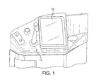
- Fig. 1 an electronic display device 10 that a pilot may use for preflight check lists and similar activities within the cockpit of an aircraft.
- the electronic display device 10 is removably mounted to a supporting structure or console 12 in the cockpit of an aircraft using the mounting assembly of the subject invention, which is described in greater detail herein below.
- the mounting assembly of the subject invention enables a pilot or crewmember to easily and quickly mount the electronic display device 10 to a supporting structure or console 12 in the cockpit of an aircraft without using any tools or manually operated fasteners or latches.
- the mounting assembly of the subject invention which his designated generally by reference numeral 100, includes a circular adapter plate 110 and a square receiver plate 210.
- the adapter plate 110 is configured for attachment to a rear surface of an electronic display device 10.
- the receiver plate 210 is configured for attachment to a supporting structure 12 in the cockpit of an aircraft.
- the adapter plate 110 and receiver plate 210 are preferably stamp formed from flat sheet metal, making this a low cost assembly to manufacture.
- the adapter plate 110 has a central alignment aperture 112 with an axially extending annular wall 114 that faces away from the rear surface of the display device 10.
- the adapter plate 110 includes a plurality of circumferentially spaced apart spokes or engagement arms 116 that extend radially outwardly from a peripheral edge 118 of the adapter plate 110.
- the adapter plate 110 has eight radially extending spokes or engagement arms 116. Those skilled in the art will readily appreciate that the number of radially spokes can vary depending upon such factors as allowable diameter, assembly force desired, structural strength required or rotation angle allowed.
- each of the radially outwardly extending engagement arms 116 of the adapter plate 110 includes an integrally formed, tangentially extending cantilevered projection 120.
- Each cantilevered projection 120 has a raised detent or bump 122 formed thereon.
- the adapter plate 110 further includes a plurality of mounting apertures 124 for receiving threaded fasteners 126 that secure the adapter plate 110 to the rear surface 15 of the display device 10, as illustrated in Fig. 3 .
- the receiver plate 210 of mounting assembly 100 has a centrally located recessed port 212 for blindly receiving the annular wall 114 of the central alignment aperture 112 of the adapter plate 110. It is envisioned that the adapter plate 110 could be aligned with the receiver plate 210 in other ways. For example, one of the spokes 116 could be omitted or offset to allow for a certain assembly orientation, or a keyway could be formed in the annular wall 114 for aligning with complementary structure in recessed port 212.
- the receiver plate 210 includes a plurality of circumferentially spaced apart cantilevered retention tabs 216 that extend in a direction tangential to the periphery of the recessed port 212.
- the cantilevered retention tabs 216 are preferably formed integral with the receiver plate 210. It is envisioned however, that the retention tabs could be formed separate from the plate and subsequently mounted to the plate using conventional metal joining techniques.
- each cantilevered retention tab 216 of the receiver plate 210 includes an upturned end section 230 for accommodating relative movement of a detent 122 formed on a cantilevered projection 118 of an engagement arm 116 of the adapter plate 110 received thereby.
- Each of the cantilevered retention tabs 216 of the receiver plate 210 also includes a recess or hole 232 for receiving and temporarily retaining or catching a detent 122 formed on a cantilevered projection 118 of an engagement arm 116 of the adapter plate 110.
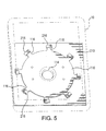
- each retention tab 216 of the receiver plate 210 is adapted and configured to receive and temporarily retain a respective engagement arm 116 of the adapter plate 110 upon axial reception of the annular wall 114 of the central alignment aperture 112 of the adapter plate 110 within the recessed port 212 of the receiver plate 210, as shown in Fig. 4 , followed by the subsequent rotation of the adapter plate 110 relative to the receiver plate 210, as shown in Fig. 5 .
- the detent 122 on the projection 118 slides past the upturned end 230 of the retention tab 216 and is captured by the recess 232 of the retention tab 216.
- the mounting assembly 100 is less susceptible to disengagement by vibrations and shocks experienced on the aircraft during flight operations, which are typically applied along discrete axes.
- the number of engagement arms 116 on the adapter plate 110 and the corresponding number of retention tabs 216 on receiver plate 210 can vary depending upon the size of the adapter plate 110 and/or the display device 10 with which it is employed. It is also envisioned that alternative blind rotational engagement structure can be employed as an alternative to the cooperating engagement arms 116 and retention tabs 216 disclosed herein. For example, a plurality of spring biased engagement clips can be employed to releasably retain the adapter plate 110 with respect to the receiver plate 210.
- the mounting assembly disclosed herein could be readily adapted for use in conjunction with any type of display device including, for example, televisions or computer monitors.
- the mounting assembly disclosed herein can be used in any situation where an electronic display device with significant mass needs to be mounted in a cavity where there is little or no access to a mount, and where the display device needs to be mounted without the use of any tools or manual latches.
Landscapes
- Engineering & Computer Science (AREA)
- Aviation & Aerospace Engineering (AREA)
- Mechanical Engineering (AREA)
- General Engineering & Computer Science (AREA)
- Devices For Indicating Variable Information By Combining Individual Elements (AREA)
Applications Claiming Priority (1)
| Application Number | Priority Date | Filing Date | Title |
|---|---|---|---|
| US13/893,495 US9027892B2 (en) | 2013-05-14 | 2013-05-14 | Rotating electronic display mount |
Publications (2)
| Publication Number | Publication Date |
|---|---|
| EP2803585A1 true EP2803585A1 (de) | 2014-11-19 |
| EP2803585B1 EP2803585B1 (de) | 2018-03-21 |
Family
ID=50980905
Family Applications (1)
| Application Number | Title | Priority Date | Filing Date |
|---|---|---|---|
| EP14168265.8A Active EP2803585B1 (de) | 2013-05-14 | 2014-05-14 | Rotierender Halter für elektronische Anzeigen |
Country Status (5)
| Country | Link |
|---|---|
| US (1) | US9027892B2 (de) |
| EP (1) | EP2803585B1 (de) |
| CN (1) | CN104149983B (de) |
| BR (1) | BR102014011496B1 (de) |
| CA (1) | CA2851883C (de) |
Cited By (2)
| Publication number | Priority date | Publication date | Assignee | Title |
|---|---|---|---|---|
| EP3115674A1 (de) * | 2015-06-19 | 2017-01-11 | Rosemount Aerospace Inc. | Werkzeugloses drehlager mit niedrigem profil |
| WO2021144530A1 (fr) * | 2020-01-17 | 2021-07-22 | Axess Vision Technology | Systeme d'assemblage d'un appareil notamment medical avec un support |
Families Citing this family (20)
| Publication number | Priority date | Publication date | Assignee | Title |
|---|---|---|---|---|
| US9335789B2 (en) * | 2013-05-10 | 2016-05-10 | Adam Merzon | System and apparatus for mounting a handheld electronic device |
| US9782003B2 (en) * | 2013-10-11 | 2017-10-10 | Viden Inc. | Rotating wall mount for display device |
| US9797547B2 (en) * | 2015-01-09 | 2017-10-24 | Brandon Meyer | Computer and monitor mounting adapter |
| US9756930B2 (en) * | 2015-04-28 | 2017-09-12 | Axon Enterprise, Inc. | Methods and apparatus for a low-profile coupler |
| AU2016372158B2 (en) * | 2015-12-15 | 2021-12-09 | Francois Gariepy | Rotating wall mount for display device |
| US9919659B2 (en) * | 2015-12-22 | 2018-03-20 | Fca Us Llc | Adjustable mobile-device holder |
| US9987950B2 (en) * | 2016-04-20 | 2018-06-05 | Ford Global Technologies, Llc | Vehicle seat electrical connector bracket assembly |
| US10030806B2 (en) * | 2016-08-30 | 2018-07-24 | Htc Corporation | Fixing support and fixing module |
| US9843849B1 (en) * | 2016-10-25 | 2017-12-12 | Christian Lasnier de Lavalette | Speaker mounting |
| US11306865B1 (en) * | 2017-06-22 | 2022-04-19 | Russ Bassett Corporation | Quick connect having a secured position and a release position |
| CN110143171B (zh) * | 2018-02-11 | 2025-06-13 | 比亚迪股份有限公司 | 用于显示终端的旋转机构以及车辆 |
| CN110154925B (zh) * | 2018-02-11 | 2022-04-15 | 比亚迪股份有限公司 | 用于调节显示终端的执行机构、安装总成和车辆 |
| CN110154923B (zh) * | 2018-02-11 | 2022-04-15 | 比亚迪股份有限公司 | 用于显示终端的旋转机构以及车辆 |
| US11118723B2 (en) * | 2019-05-24 | 2021-09-14 | Chicago Maritme Supply, LLC | Mounting plate for computer |
| CN111591454B (zh) * | 2020-05-29 | 2022-01-21 | 中国商用飞机有限责任公司 | 一种飞机驾驶舱安装便携式显示器的组合装置 |
| CN111536402B (zh) * | 2020-06-09 | 2025-04-01 | 江苏开璇智能科技有限公司 | 一种多用途二自由度监测云台 |
| US11766144B2 (en) * | 2020-06-12 | 2023-09-26 | Christopher Levi Kraus | Container stability mounting apparatus |
| US11780378B2 (en) | 2020-12-21 | 2023-10-10 | Harman International Industries, Incorporated | Tweeter flush, surface, and starfish mount installation |
| EP4344957B1 (de) * | 2022-09-28 | 2025-05-21 | Volvo Truck Corporation | Modulare anzeigebefestigung |
| US12111477B1 (en) * | 2023-03-20 | 2024-10-08 | Vuzix Corporation | Mounting system for head-mounted devices |
Citations (7)
| Publication number | Priority date | Publication date | Assignee | Title |
|---|---|---|---|---|
| US6302617B1 (en) * | 1996-08-20 | 2001-10-16 | Gerhard Rumpp | Coupling device for a vehicle |
| US20060108137A1 (en) * | 2004-11-23 | 2006-05-25 | Smith David W | Quick connect electrical junction box assembly |
| US20090103748A1 (en) * | 2006-03-15 | 2009-04-23 | Fujitsu Ten Limited | Sound Generating Apparatus |
| DE102008034779A1 (de) * | 2008-07-25 | 2010-01-28 | Airbus Deutschland Gmbh | Vorrichtung zur drehbaren Lagerung eines Flugzeuginnenausstattungsbauteils |
| US20100329486A1 (en) * | 2008-01-04 | 2010-12-30 | Henning Scheel | Oscillator for a flat loudspeaker, flat loudspeaker and vehicle |
| US20110031373A1 (en) * | 2006-01-20 | 2011-02-10 | Avionics Support Group, Inc. | Electronic display mount |
| US8025528B2 (en) * | 2010-01-21 | 2011-09-27 | Smith Benjamin J | Quick mounting device with modules |
Family Cites Families (33)
| Publication number | Priority date | Publication date | Assignee | Title |
|---|---|---|---|---|
| US815627A (en) * | 1905-07-11 | 1906-03-20 | Samuel Oldham | Hose-coupling. |
| US2283974A (en) * | 1940-12-06 | 1942-05-26 | Hanlon Waters Inc | Coupling |
| US3229948A (en) * | 1963-11-20 | 1966-01-18 | Bronze Inc | Vase locking device |
| US3908942A (en) * | 1974-04-25 | 1975-09-30 | Morton Metalcraft Co | Mounting means for television sets and the like |
| JPS57155190A (en) * | 1981-03-21 | 1982-09-25 | Shiyunyuu So | Metal fitting for channel type lashing |
| US4880191A (en) * | 1984-07-05 | 1989-11-14 | Unisys Corporation | Mounting arrangement for display terminal |
| US4570892A (en) | 1984-12-11 | 1986-02-18 | Zenith Electronics Corporation | Tiltable rotating display monitor mount |
| CA1271832A (en) * | 1986-03-19 | 1990-07-17 | Sadamasa Tanaka | Wiring-device mounting structure |
| US5626435A (en) * | 1993-10-29 | 1997-05-06 | Rockinger Spezialfabrik Fur Anhangerkupplungen Gmbh & Co. | Coupling assembly |
| US6220557B1 (en) * | 1999-09-28 | 2001-04-24 | Michael P. Ziaylek | Mounting bracket means for detachably supporting a generally cylindrically-shaped member upon a wall surface |
| US6588719B1 (en) | 2002-09-10 | 2003-07-08 | Hollingsead International, Inc. | Mounting and support bracket |
| US7100879B2 (en) * | 2002-11-27 | 2006-09-05 | Dimension One Spas | Speaker bracket |
| US6929226B1 (en) * | 2003-08-11 | 2005-08-16 | The United States Of America As Represented By The Secretary Of The Army | Twist lock mounting system |
| CN2763941Y (zh) * | 2004-12-08 | 2006-03-08 | 鸿富锦精密工业(深圳)有限公司 | 数据存储器固定装置 |
| US7673838B2 (en) * | 2005-02-16 | 2010-03-09 | Innovative Office Products, Inc. | Quick release assembly for an electronic device |
| US7317613B2 (en) * | 2005-10-31 | 2008-01-08 | Hewlett-Packard Development Company, L.P. | Electronic device quick connect system |
| JP4796837B2 (ja) * | 2005-12-27 | 2011-10-19 | Necディスプレイソリューションズ株式会社 | ディスプレイと支持具の連結構造およびディスプレイ |
| US7686250B2 (en) | 2006-01-20 | 2010-03-30 | Fortes Hugo L | Electronic display mount |
| DE202006004407U1 (de) * | 2006-03-17 | 2007-07-19 | Mann+Hummel Gmbh | Anschluss für ein rohrförmiges Luftführungselement an einem Turbolader |
| TWM307256U (en) | 2006-08-16 | 2007-03-01 | Jarllytec Co Ltd | Fastening structure with rapid stevedoring features |
| US7303171B1 (en) | 2006-11-21 | 2007-12-04 | Supa Technology Co., Ltd. | Adjustable fixing mount |
| WO2009030474A1 (en) * | 2007-09-07 | 2009-03-12 | Hunter Douglas Industries B.V. | Universal connector |
| US8185985B2 (en) * | 2007-10-26 | 2012-05-29 | Illinois Tool Works Inc. | Load bearing surface |
| US8534060B1 (en) * | 2008-08-01 | 2013-09-17 | Hydro-Gear Limited Partnership | Drive device |
| CN201278621Y (zh) | 2008-08-29 | 2009-07-22 | 鸿富锦精密工业(深圳)有限公司 | 滑动翻盖式电子装置 |
| US8215583B2 (en) | 2008-09-22 | 2012-07-10 | Pentastar Aviation, Inc. | Articulating yoke mount |
| US8191844B2 (en) * | 2009-01-09 | 2012-06-05 | William Pennino | Container holder for use on a bicycle |
| US8308114B2 (en) | 2009-02-25 | 2012-11-13 | Tensolite LLC | Electronic flight bag mounting bracket |
| CN102215651A (zh) * | 2010-04-07 | 2011-10-12 | 深圳富泰宏精密工业有限公司 | 卡扣结构及具有该卡扣结构的便携式电子装置壳体 |
| CN102291953A (zh) * | 2010-06-15 | 2011-12-21 | 鸿富锦精密工业(深圳)有限公司 | 安装电子设备的机柜 |
| TWI434003B (zh) * | 2011-09-09 | 2014-04-11 | Benq Corp | 可拆卸掛勾及具有掛勾之支撐架 |
| CN103062580B (zh) * | 2011-10-18 | 2015-10-21 | 纬创资通股份有限公司 | 用来固定屏幕的屏幕固定机构及显示装置 |
| CN103309415A (zh) * | 2012-03-08 | 2013-09-18 | 鸿富锦精密工业(深圳)有限公司 | 硬盘固定装置 |
-
2013
- 2013-05-14 US US13/893,495 patent/US9027892B2/en active Active
-
2014
- 2014-05-08 CA CA2851883A patent/CA2851883C/en active Active
- 2014-05-13 BR BR102014011496-3A patent/BR102014011496B1/pt active IP Right Grant
- 2014-05-14 EP EP14168265.8A patent/EP2803585B1/de active Active
- 2014-05-14 CN CN201410201506.9A patent/CN104149983B/zh active Active
Patent Citations (7)
| Publication number | Priority date | Publication date | Assignee | Title |
|---|---|---|---|---|
| US6302617B1 (en) * | 1996-08-20 | 2001-10-16 | Gerhard Rumpp | Coupling device for a vehicle |
| US20060108137A1 (en) * | 2004-11-23 | 2006-05-25 | Smith David W | Quick connect electrical junction box assembly |
| US20110031373A1 (en) * | 2006-01-20 | 2011-02-10 | Avionics Support Group, Inc. | Electronic display mount |
| US20090103748A1 (en) * | 2006-03-15 | 2009-04-23 | Fujitsu Ten Limited | Sound Generating Apparatus |
| US20100329486A1 (en) * | 2008-01-04 | 2010-12-30 | Henning Scheel | Oscillator for a flat loudspeaker, flat loudspeaker and vehicle |
| DE102008034779A1 (de) * | 2008-07-25 | 2010-01-28 | Airbus Deutschland Gmbh | Vorrichtung zur drehbaren Lagerung eines Flugzeuginnenausstattungsbauteils |
| US8025528B2 (en) * | 2010-01-21 | 2011-09-27 | Smith Benjamin J | Quick mounting device with modules |
Cited By (5)
| Publication number | Priority date | Publication date | Assignee | Title |
|---|---|---|---|---|
| EP3115674A1 (de) * | 2015-06-19 | 2017-01-11 | Rosemount Aerospace Inc. | Werkzeugloses drehlager mit niedrigem profil |
| US9604580B2 (en) | 2015-06-19 | 2017-03-28 | Rosemount Aerospace, Inc. | Tool-less low profile rotation mount |
| WO2021144530A1 (fr) * | 2020-01-17 | 2021-07-22 | Axess Vision Technology | Systeme d'assemblage d'un appareil notamment medical avec un support |
| FR3106265A1 (fr) * | 2020-01-17 | 2021-07-23 | Axess Vision Technology | Système d’assemblage d’un appareil notamment médical avec un support |
| US12313210B2 (en) | 2020-01-17 | 2025-05-27 | Axess Vision Technology | System for joining a device, in particular a medical device, to a support |
Also Published As
| Publication number | Publication date |
|---|---|
| CA2851883C (en) | 2021-08-17 |
| CA2851883A1 (en) | 2014-11-14 |
| EP2803585B1 (de) | 2018-03-21 |
| US20140339385A1 (en) | 2014-11-20 |
| CN104149983A (zh) | 2014-11-19 |
| BR102014011496A2 (pt) | 2015-12-01 |
| US9027892B2 (en) | 2015-05-12 |
| CN104149983B (zh) | 2018-03-30 |
| BR102014011496B1 (pt) | 2021-12-07 |
Similar Documents
| Publication | Publication Date | Title |
|---|---|---|
| CA2851883C (en) | Rotating electronic display mount | |
| EP2808593B1 (de) | Rotierender elektronischer Anzeigeadapter | |
| EP2569187B1 (de) | Kupplungseinheit | |
| EP2401199B1 (de) | Befestigungswinkel für electronic flight bag | |
| US7417866B1 (en) | Electronic equipment module mounting apparatus and method | |
| WO2011043873A1 (en) | Electronic flight bag mounting system | |
| EP2947370B1 (de) | Anzeigemontagevorrichtung | |
| CA2927670C (en) | Infrastructure for mobile devices and electronic loose equipment | |
| WO2001096780A1 (en) | Mounting bracket | |
| JP2012517562A (ja) | 航空機内のモジュール式部材の締結装置 | |
| EP3115674A1 (de) | Werkzeugloses drehlager mit niedrigem profil | |
| US10734773B2 (en) | Infrastructure for mobile devices and electronic loose equipment | |
| US10520128B2 (en) | Touch screen tablet holder for aircraft yoke assembly | |
| EP3000735B1 (de) | Schnellspanner für ein Luftbetankungssystem mit Trichter und Korb | |
| CN106254728B (zh) | 摄像机调整机构和方法以及飞机监视系统 | |
| JP6539445B2 (ja) | 単一通路取付システム | |
| US20100301080A1 (en) | Pivot mount assembly | |
| EP4236305A1 (de) | Befestigungssystem zur montage einer kamera an einer trägerstruktur | |
| CN215043765U (zh) | 一种翻转式机载导航仪固定装置 | |
| JP2010121648A (ja) | スタンド装置 | |
| US20100301185A1 (en) | Pivot mount assembly | |
| EP3507539B1 (de) | Scharnieranordnung mit einstellbarem drehmoment für eine kopfstütze | |
| CN121341426A (zh) | 一种电子飞行手册固定调节装置 |
Legal Events
| Date | Code | Title | Description |
|---|---|---|---|
| PUAI | Public reference made under article 153(3) epc to a published international application that has entered the european phase |
Free format text: ORIGINAL CODE: 0009012 |
|
| 17P | Request for examination filed |
Effective date: 20140514 |
|
| AK | Designated contracting states |
Kind code of ref document: A1 Designated state(s): AL AT BE BG CH CY CZ DE DK EE ES FI FR GB GR HR HU IE IS IT LI LT LU LV MC MK MT NL NO PL PT RO RS SE SI SK SM TR |
|
| AX | Request for extension of the european patent |
Extension state: BA ME |
|
| R17P | Request for examination filed (corrected) |
Effective date: 20150519 |
|
| RBV | Designated contracting states (corrected) |
Designated state(s): AL AT BE BG CH CY CZ DE DK EE ES FI FR GB GR HR HU IE IS IT LI LT LU LV MC MK MT NL NO PL PT RO RS SE SI SK SM TR |
|
| 17Q | First examination report despatched |
Effective date: 20160517 |
|
| STAA | Information on the status of an ep patent application or granted ep patent |
Free format text: STATUS: EXAMINATION IS IN PROGRESS |
|
| GRAP | Despatch of communication of intention to grant a patent |
Free format text: ORIGINAL CODE: EPIDOSNIGR1 |
|
| STAA | Information on the status of an ep patent application or granted ep patent |
Free format text: STATUS: GRANT OF PATENT IS INTENDED |
|
| INTG | Intention to grant announced |
Effective date: 20170927 |
|
| GRAS | Grant fee paid |
Free format text: ORIGINAL CODE: EPIDOSNIGR3 |
|
| GRAA | (expected) grant |
Free format text: ORIGINAL CODE: 0009210 |
|
| STAA | Information on the status of an ep patent application or granted ep patent |
Free format text: STATUS: THE PATENT HAS BEEN GRANTED |
|
| AK | Designated contracting states |
Kind code of ref document: B1 Designated state(s): AL AT BE BG CH CY CZ DE DK EE ES FI FR GB GR HR HU IE IS IT LI LT LU LV MC MK MT NL NO PL PT RO RS SE SI SK SM TR |
|
| REG | Reference to a national code |
Ref country code: GB Ref legal event code: FG4D |
|
| REG | Reference to a national code |
Ref country code: CH Ref legal event code: EP |
|
| REG | Reference to a national code |
Ref country code: AT Ref legal event code: REF Ref document number: 980806 Country of ref document: AT Kind code of ref document: T Effective date: 20180415 |
|
| REG | Reference to a national code |
Ref country code: IE Ref legal event code: FG4D |
|
| REG | Reference to a national code |
Ref country code: DE Ref legal event code: R096 Ref document number: 602014022502 Country of ref document: DE |
|
| REG | Reference to a national code |
Ref country code: FR Ref legal event code: PLFP Year of fee payment: 5 |
|
| REG | Reference to a national code |
Ref country code: NL Ref legal event code: MP Effective date: 20180321 |
|
| PG25 | Lapsed in a contracting state [announced via postgrant information from national office to epo] |
Ref country code: CY Free format text: LAPSE BECAUSE OF FAILURE TO SUBMIT A TRANSLATION OF THE DESCRIPTION OR TO PAY THE FEE WITHIN THE PRESCRIBED TIME-LIMIT Effective date: 20180321 Ref country code: LT Free format text: LAPSE BECAUSE OF FAILURE TO SUBMIT A TRANSLATION OF THE DESCRIPTION OR TO PAY THE FEE WITHIN THE PRESCRIBED TIME-LIMIT Effective date: 20180321 Ref country code: NO Free format text: LAPSE BECAUSE OF FAILURE TO SUBMIT A TRANSLATION OF THE DESCRIPTION OR TO PAY THE FEE WITHIN THE PRESCRIBED TIME-LIMIT Effective date: 20180621 Ref country code: HR Free format text: LAPSE BECAUSE OF FAILURE TO SUBMIT A TRANSLATION OF THE DESCRIPTION OR TO PAY THE FEE WITHIN THE PRESCRIBED TIME-LIMIT Effective date: 20180321 Ref country code: FI Free format text: LAPSE BECAUSE OF FAILURE TO SUBMIT A TRANSLATION OF THE DESCRIPTION OR TO PAY THE FEE WITHIN THE PRESCRIBED TIME-LIMIT Effective date: 20180321 |
|
| REG | Reference to a national code |
Ref country code: LT Ref legal event code: MG4D |
|
| REG | Reference to a national code |
Ref country code: AT Ref legal event code: MK05 Ref document number: 980806 Country of ref document: AT Kind code of ref document: T Effective date: 20180321 |
|
| PG25 | Lapsed in a contracting state [announced via postgrant information from national office to epo] |
Ref country code: RS Free format text: LAPSE BECAUSE OF FAILURE TO SUBMIT A TRANSLATION OF THE DESCRIPTION OR TO PAY THE FEE WITHIN THE PRESCRIBED TIME-LIMIT Effective date: 20180321 Ref country code: LV Free format text: LAPSE BECAUSE OF FAILURE TO SUBMIT A TRANSLATION OF THE DESCRIPTION OR TO PAY THE FEE WITHIN THE PRESCRIBED TIME-LIMIT Effective date: 20180321 Ref country code: SE Free format text: LAPSE BECAUSE OF FAILURE TO SUBMIT A TRANSLATION OF THE DESCRIPTION OR TO PAY THE FEE WITHIN THE PRESCRIBED TIME-LIMIT Effective date: 20180321 Ref country code: GR Free format text: LAPSE BECAUSE OF FAILURE TO SUBMIT A TRANSLATION OF THE DESCRIPTION OR TO PAY THE FEE WITHIN THE PRESCRIBED TIME-LIMIT Effective date: 20180622 Ref country code: BG Free format text: LAPSE BECAUSE OF FAILURE TO SUBMIT A TRANSLATION OF THE DESCRIPTION OR TO PAY THE FEE WITHIN THE PRESCRIBED TIME-LIMIT Effective date: 20180621 |
|
| PG25 | Lapsed in a contracting state [announced via postgrant information from national office to epo] |
Ref country code: ES Free format text: LAPSE BECAUSE OF FAILURE TO SUBMIT A TRANSLATION OF THE DESCRIPTION OR TO PAY THE FEE WITHIN THE PRESCRIBED TIME-LIMIT Effective date: 20180321 Ref country code: PL Free format text: LAPSE BECAUSE OF FAILURE TO SUBMIT A TRANSLATION OF THE DESCRIPTION OR TO PAY THE FEE WITHIN THE PRESCRIBED TIME-LIMIT Effective date: 20180321 Ref country code: AL Free format text: LAPSE BECAUSE OF FAILURE TO SUBMIT A TRANSLATION OF THE DESCRIPTION OR TO PAY THE FEE WITHIN THE PRESCRIBED TIME-LIMIT Effective date: 20180321 Ref country code: IT Free format text: LAPSE BECAUSE OF FAILURE TO SUBMIT A TRANSLATION OF THE DESCRIPTION OR TO PAY THE FEE WITHIN THE PRESCRIBED TIME-LIMIT Effective date: 20180321 Ref country code: EE Free format text: LAPSE BECAUSE OF FAILURE TO SUBMIT A TRANSLATION OF THE DESCRIPTION OR TO PAY THE FEE WITHIN THE PRESCRIBED TIME-LIMIT Effective date: 20180321 Ref country code: NL Free format text: LAPSE BECAUSE OF FAILURE TO SUBMIT A TRANSLATION OF THE DESCRIPTION OR TO PAY THE FEE WITHIN THE PRESCRIBED TIME-LIMIT Effective date: 20180321 Ref country code: RO Free format text: LAPSE BECAUSE OF FAILURE TO SUBMIT A TRANSLATION OF THE DESCRIPTION OR TO PAY THE FEE WITHIN THE PRESCRIBED TIME-LIMIT Effective date: 20180321 |
|
| PG25 | Lapsed in a contracting state [announced via postgrant information from national office to epo] |
Ref country code: SM Free format text: LAPSE BECAUSE OF FAILURE TO SUBMIT A TRANSLATION OF THE DESCRIPTION OR TO PAY THE FEE WITHIN THE PRESCRIBED TIME-LIMIT Effective date: 20180321 Ref country code: CZ Free format text: LAPSE BECAUSE OF FAILURE TO SUBMIT A TRANSLATION OF THE DESCRIPTION OR TO PAY THE FEE WITHIN THE PRESCRIBED TIME-LIMIT Effective date: 20180321 Ref country code: AT Free format text: LAPSE BECAUSE OF FAILURE TO SUBMIT A TRANSLATION OF THE DESCRIPTION OR TO PAY THE FEE WITHIN THE PRESCRIBED TIME-LIMIT Effective date: 20180321 Ref country code: SK Free format text: LAPSE BECAUSE OF FAILURE TO SUBMIT A TRANSLATION OF THE DESCRIPTION OR TO PAY THE FEE WITHIN THE PRESCRIBED TIME-LIMIT Effective date: 20180321 |
|
| REG | Reference to a national code |
Ref country code: CH Ref legal event code: PL |
|
| PG25 | Lapsed in a contracting state [announced via postgrant information from national office to epo] |
Ref country code: PT Free format text: LAPSE BECAUSE OF FAILURE TO SUBMIT A TRANSLATION OF THE DESCRIPTION OR TO PAY THE FEE WITHIN THE PRESCRIBED TIME-LIMIT Effective date: 20180723 |
|
| REG | Reference to a national code |
Ref country code: DE Ref legal event code: R097 Ref document number: 602014022502 Country of ref document: DE |
|
| PLBE | No opposition filed within time limit |
Free format text: ORIGINAL CODE: 0009261 |
|
| STAA | Information on the status of an ep patent application or granted ep patent |
Free format text: STATUS: NO OPPOSITION FILED WITHIN TIME LIMIT |
|
| REG | Reference to a national code |
Ref country code: BE Ref legal event code: MM Effective date: 20180531 |
|
| PG25 | Lapsed in a contracting state [announced via postgrant information from national office to epo] |
Ref country code: DK Free format text: LAPSE BECAUSE OF FAILURE TO SUBMIT A TRANSLATION OF THE DESCRIPTION OR TO PAY THE FEE WITHIN THE PRESCRIBED TIME-LIMIT Effective date: 20180321 Ref country code: MC Free format text: LAPSE BECAUSE OF FAILURE TO SUBMIT A TRANSLATION OF THE DESCRIPTION OR TO PAY THE FEE WITHIN THE PRESCRIBED TIME-LIMIT Effective date: 20180321 |
|
| REG | Reference to a national code |
Ref country code: IE Ref legal event code: MM4A |
|
| 26N | No opposition filed |
Effective date: 20190102 |
|
| PG25 | Lapsed in a contracting state [announced via postgrant information from national office to epo] |
Ref country code: LI Free format text: LAPSE BECAUSE OF NON-PAYMENT OF DUE FEES Effective date: 20180531 Ref country code: CH Free format text: LAPSE BECAUSE OF NON-PAYMENT OF DUE FEES Effective date: 20180531 |
|
| PG25 | Lapsed in a contracting state [announced via postgrant information from national office to epo] |
Ref country code: LU Free format text: LAPSE BECAUSE OF NON-PAYMENT OF DUE FEES Effective date: 20180514 |
|
| PG25 | Lapsed in a contracting state [announced via postgrant information from national office to epo] |
Ref country code: IE Free format text: LAPSE BECAUSE OF NON-PAYMENT OF DUE FEES Effective date: 20180514 |
|
| PG25 | Lapsed in a contracting state [announced via postgrant information from national office to epo] |
Ref country code: BE Free format text: LAPSE BECAUSE OF NON-PAYMENT OF DUE FEES Effective date: 20180531 Ref country code: SI Free format text: LAPSE BECAUSE OF FAILURE TO SUBMIT A TRANSLATION OF THE DESCRIPTION OR TO PAY THE FEE WITHIN THE PRESCRIBED TIME-LIMIT Effective date: 20180321 |
|
| PG25 | Lapsed in a contracting state [announced via postgrant information from national office to epo] |
Ref country code: MT Free format text: LAPSE BECAUSE OF NON-PAYMENT OF DUE FEES Effective date: 20180514 |
|
| PG25 | Lapsed in a contracting state [announced via postgrant information from national office to epo] |
Ref country code: TR Free format text: LAPSE BECAUSE OF FAILURE TO SUBMIT A TRANSLATION OF THE DESCRIPTION OR TO PAY THE FEE WITHIN THE PRESCRIBED TIME-LIMIT Effective date: 20180321 |
|
| PG25 | Lapsed in a contracting state [announced via postgrant information from national office to epo] |
Ref country code: HU Free format text: LAPSE BECAUSE OF FAILURE TO SUBMIT A TRANSLATION OF THE DESCRIPTION OR TO PAY THE FEE WITHIN THE PRESCRIBED TIME-LIMIT; INVALID AB INITIO Effective date: 20140514 |
|
| PG25 | Lapsed in a contracting state [announced via postgrant information from national office to epo] |
Ref country code: MK Free format text: LAPSE BECAUSE OF NON-PAYMENT OF DUE FEES Effective date: 20180321 |
|
| PG25 | Lapsed in a contracting state [announced via postgrant information from national office to epo] |
Ref country code: IS Free format text: LAPSE BECAUSE OF FAILURE TO SUBMIT A TRANSLATION OF THE DESCRIPTION OR TO PAY THE FEE WITHIN THE PRESCRIBED TIME-LIMIT Effective date: 20180721 |
|
| PGFP | Annual fee paid to national office [announced via postgrant information from national office to epo] |
Ref country code: DE Payment date: 20250423 Year of fee payment: 12 |
|
| PGFP | Annual fee paid to national office [announced via postgrant information from national office to epo] |
Ref country code: GB Payment date: 20250423 Year of fee payment: 12 |
|
| PGFP | Annual fee paid to national office [announced via postgrant information from national office to epo] |
Ref country code: FR Payment date: 20250423 Year of fee payment: 12 |