EP2803573B1 - Passenger interface units and assemblies - Google Patents
Passenger interface units and assemblies Download PDFInfo
- Publication number
- EP2803573B1 EP2803573B1 EP14168595.8A EP14168595A EP2803573B1 EP 2803573 B1 EP2803573 B1 EP 2803573B1 EP 14168595 A EP14168595 A EP 14168595A EP 2803573 B1 EP2803573 B1 EP 2803573B1
- Authority
- EP
- European Patent Office
- Prior art keywords
- unit
- light
- module
- ion exchange
- high ion
- Prior art date
- Legal status (The legal status is an assumption and is not a legal conclusion. Google has not performed a legal analysis and makes no representation as to the accuracy of the status listed.)
- Active
Links
Images
Classifications
-
- A—HUMAN NECESSITIES
- A62—LIFE-SAVING; FIRE-FIGHTING
- A62B—DEVICES, APPARATUS OR METHODS FOR LIFE-SAVING
- A62B25/00—Devices for storing or holding or carrying respiratory or breathing apparatus
- A62B25/005—Devices for storing or holding or carrying respiratory or breathing apparatus for high altitude
-
- B—PERFORMING OPERATIONS; TRANSPORTING
- B64—AIRCRAFT; AVIATION; COSMONAUTICS
- B64D—EQUIPMENT FOR FITTING IN OR TO AIRCRAFT; FLIGHT SUITS; PARACHUTES; ARRANGEMENTS OR MOUNTING OF POWER PLANTS OR PROPULSION TRANSMISSIONS IN AIRCRAFT
- B64D11/00—Passenger or crew accommodation; Flight-deck installations not otherwise provided for
-
- A—HUMAN NECESSITIES
- A62—LIFE-SAVING; FIRE-FIGHTING
- A62B—DEVICES, APPARATUS OR METHODS FOR LIFE-SAVING
- A62B18/00—Breathing masks or helmets, e.g. affording protection against chemical agents or for use at high altitudes or incorporating a pump or compressor for reducing the inhalation effort
- A62B18/02—Masks
-
- A—HUMAN NECESSITIES
- A62—LIFE-SAVING; FIRE-FIGHTING
- A62B—DEVICES, APPARATUS OR METHODS FOR LIFE-SAVING
- A62B7/00—Respiratory apparatus
- A62B7/14—Respiratory apparatus for high-altitude aircraft
-
- B—PERFORMING OPERATIONS; TRANSPORTING
- B64—AIRCRAFT; AVIATION; COSMONAUTICS
- B64D—EQUIPMENT FOR FITTING IN OR TO AIRCRAFT; FLIGHT SUITS; PARACHUTES; ARRANGEMENTS OR MOUNTING OF POWER PLANTS OR PROPULSION TRANSMISSIONS IN AIRCRAFT
- B64D47/00—Equipment not otherwise provided for
- B64D47/02—Arrangements or adaptations of signal or lighting devices
-
- B—PERFORMING OPERATIONS; TRANSPORTING
- B64—AIRCRAFT; AVIATION; COSMONAUTICS
- B64D—EQUIPMENT FOR FITTING IN OR TO AIRCRAFT; FLIGHT SUITS; PARACHUTES; ARRANGEMENTS OR MOUNTING OF POWER PLANTS OR PROPULSION TRANSMISSIONS IN AIRCRAFT
- B64D11/00—Passenger or crew accommodation; Flight-deck installations not otherwise provided for
- B64D2011/0038—Illumination systems for cabins as a whole
-
- B—PERFORMING OPERATIONS; TRANSPORTING
- B64—AIRCRAFT; AVIATION; COSMONAUTICS
- B64D—EQUIPMENT FOR FITTING IN OR TO AIRCRAFT; FLIGHT SUITS; PARACHUTES; ARRANGEMENTS OR MOUNTING OF POWER PLANTS OR PROPULSION TRANSMISSIONS IN AIRCRAFT
- B64D11/00—Passenger or crew accommodation; Flight-deck installations not otherwise provided for
- B64D2011/0053—Cabin passenger reading lights
-
- B—PERFORMING OPERATIONS; TRANSPORTING
- B64—AIRCRAFT; AVIATION; COSMONAUTICS
- B64D—EQUIPMENT FOR FITTING IN OR TO AIRCRAFT; FLIGHT SUITS; PARACHUTES; ARRANGEMENTS OR MOUNTING OF POWER PLANTS OR PROPULSION TRANSMISSIONS IN AIRCRAFT
- B64D13/00—Arrangements or adaptations of air-treatment apparatus for aircraft crew or passengers, or freight space, or structural parts of the aircraft
- B64D2013/003—Cabin ventilation nozzles
Definitions
- the embodiments disclosed herein relate generally to passenger interface systems employed in interiors of transport vehicles, especially aircraft interior cabins.
- the traditional Passenger Service Units (PSUs) for executive transport aircraft typically comprise an individual assembly that merges the functions of providing the passenger with an overhead reading light and an air outlet.
- PSUs are set apart by concealed compartments containing either an oxygen mask (that by certification is also required to be available to each individual passenger) or a speaker (which allows the passenger to hear audio from the on-board PA or personal entertainment systems).
- the PSU will be provided with a screen or monitor for displaying images associated with a GPS-driven "moving map" of the aircraft route or video images associated with the passenger's in-flight entertainment system (e.g., movies, games and the like).
- the moving map and the in-flight entertainment system share the same screen or monitor.
- the passenger will need to operate a hand-held controller that is within reach.
- the reading light, air vent and oxygen masks are located in an overhead console while the personal screen associated with in-flight entertainment systems are located in front of or at the side of the passenger's seat to provide optimum viewing angles.
- the controls for all such systems are thus typically distributed about the passenger in different locations such that navigation between all systems requires different switches and controls. These distributed controls for the various passenger-operated comfort and entertainment systems therefore can result in an undesirable travel experience for the passenger.
- EP 2 172 129 A2 describes an illumination device which can be integrated into a surface which may be an interior surface of a vehicle.
- the illumination device comprises a transparent plate, a support frame and light sources behind the transparent plate. Part of the transparent plate is covered by an opaque layer.
- US 2010/245130 A1 describes an intelligent and flexible display module for displaying display information, in particular a display module for displaying passenger-specific display information in an aircraft and a method for operating such a display module.
- a module of a passenger interface unit for an overhead valence of an aircraft according to claim 1 is disclosed.
- a support panel having a touch screen cut-out region sized and configured to allow the touch screen unit to be positioned therein such that the touch screen unit is in contact with the rear surface of the high ion exchange glass panel.
- the opaque printed coating layer will thus have an unpainted transparent region that is in registry with the touch screen cut-out region.
- the light-emitting unit will comprise an accent lighting unit for providing visible accent light through the high ion exchange glass panel.
- the support panel will include an accent lighting unit cut-out region for accommodating at least a part of the accent lighting unit and the opaque printed coating layer will comprise an unpainted transparent accent lighting unit window in registry with the accent lighting unit cut-out region of the support panel. In such a manner, visible light emitted by the accent lighting unit will be visibly perceived from a front surface of the high ion exchange glass panel.
- the light-emitting unit may comprise an advisory lighting unit.
- the printed opaque layer includes an advisory window comprised of indicia corresponding to desired passenger advisory information when illuminated by the advisory lighting unit.
- the support panel will thus include an advisory light unit cut-out region sized and configured to allow the advisory light unit to be positioned therein such that the advisory light unit is supported by the support panel behind (and in some embodiments in contact with) the rear surface of the high ion exchange glass panel.
- Passenger interface units may include multiple modules, e.g., pairs of mirror image modules.
- the passenger interface units will be employed in an aircraft cabin.
- the passenger service unit may include a housing structure which houses at least one oxygen mask for delivery of oxygen to a passenger, and a removable panel covering the oxygen mask.
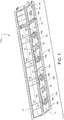
- FIG. 1 depicts a front perspective view (i.e., as viewed by a passenger) of a passenger service unit PSU provided in an overhead valence assembly 10.
- the valence assembly 10 provides a housing structure to contain oxygen masks (not shown) behind removable panels 12.
- oxygen masks can be deployed by the automated release of the panels 12.
- the valence 10 of the PSU also contains pairs of passenger interface units 14a, 14b in accordance with an embodiment of the present invention.
- the units 14a, 14b are generally mirror images of one another for aesthetics but each respectively provides for co-located control units including a reading light unit 16a, 16b, an air vent unit 18a, 18b and a touch screen unit 20a, 20b positioned therebetween.
- An accent light 22a, 22b may also be provided in each of the modules 14a, 14b, respectively, so as to highlight the passenger-controlled reading light units 16a, 16b, air vent units 18a, 18b and touch screen units 20a, 20b.
- the accent light 22a, 22b is in the form of a generally elongated U-shaped lighting trace to provide suitable aesthetics as well as functional illumination of the co-located control units.
- Selected ones of the passenger interface units 14a and/or 14b may also be provided with advisory indicators 24a, 24b (e.g., signage and/or indicia which advises the passenger of certain in-flight requirements such as no smoking, seat belt use and the like).
- the modules 14a, 14b are separated from one another by an audio speaker unit 26 which may provide audio output from the on-board passenger address and on-board entertainment systems.
- the PSU may also be provided with an auxiliary passenger interface unit 30 which unlike the unit 10 does not include a module 14a or 14b, but instead may include only a reading light unit 30a and an air vent unit 30b.
- the passenger interface unit 30 may be provided in those instances where spatial constraints dictate that less functionality is required.
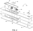
- FIG. 2 depicts an exploded rear perspective view of a representative module 14b, it being understood that the module 14a is substantially identical to but a mirror image of the depicted module 14b.
- the module 14b is a laminated structure comprised primarily of a rigid exterior glass panel (preferably high ion exchange glass panel, e.g., HIETM glass commercially available from Abrisa Technologies) panel 40 which is bonded to an interior composite support panel 42 by way of a suitable adhesive layer (schematically depicted by the double dash line identified by reference numeral 44 in FIG. 2 ).
- the glass panel 40 may have a thickness in the range of about 0.1 mm to about 2.0 mm, preferably about 1.0 mm.
- the interior composite support panel 42 may have a thickness in the range of about 3.0 mm to about 12.7 mm, preferably about 6.35 mm.
- the back surface of the glass panel 40 includes an opaque painted coating layer (schematically depicted by reference numeral 46) which masks visible light except in those unpainted (and hence light transparent) regions corresponding to a generally elongate U-shaped accent light window 46a, a touch screen window 46b and an advisory light window 46c.
- Each of the windows 46a, 46b and 46c are thus aligned with am accent lighting unit 50, a touch screen unit 52 and an advisory light unit 54 mounted physically to the support panel 42 in cut out regions 42a, 42b and 42c, respectively.
- the glass panel 42 (and the painted layer 46 thereon) and the support panel 42 are provided with aligned cut-out regions 60 and 62 therein so as to permit the mounting of the air vent and reading light units 18b, 16b, respectively.
- the air vent and reading light units 18b, 16b will each protrude outwardly from the front surface of the glass panel 40 so as to be capable of physical manipulation and access by the passenger.
- the accent light unit 50 may, for example, be an elongated strip of light-emitting diodes (LEDs) of desired color(s) that can be illuminated as desired to provide accent lighting to the interior cabin space in the vicinity of the passenger.
- LEDs light-emitting diodes
- the touch screen unit 52 is in and of itself conventional and is either connected to or integrally includes a suitable processor for displaying control icons corresponding to the comfort and/or entertainment units that are subject to passenger control.
- the touch screen unit 52 may display a menu of connected devices which can be touched to access submenus for further control of the selected device.
- the advisory light unit can simply be an on-off type of LED light illumination which can then be visibly perceived through printed indicia of the layer 46 via windows 46c thereby communication the desired passenger advisory information (e.g., no smoking, seat belt fastened and the like).
- the touch screen unit 52 may be in the form of a monitor which provides quick feedback from the moving map or other summarized flight information (e.g., time to arrival, current location and/or flight data such as altitude ground speed and the like) without disrupting on-going entertainment.
- the touch screen unit 52 may provide redundancy for the main function buttons in the cabin, such as the passenger's table light, reading light and flight attendant call button that is displayed on the unit 52 when activated by the unit's proximity sensor.
- the support panel 42 is preferably a relatively light weight but high strength carbon and/or glass fiber-reinforced resin composite panel.
- the support panel 42 may itself be formed of a lightweight but stiff composite honeycomb core structure laminated to exterior composite skin layers.
- the module 14b will thus be presented to the passenger as essentially a flat glass panel representing the front surface of the glass panel 40 through which the accent light provided by accent light unit 50, touch screen controls provided by the touch screen panel unit 52 and advisory indicators provided by the advisory light unit 54 are visible. Moreover the touch screen panel 52 may be controlled by the passenger by virtue of its operative interaction with the glass panel 40. In such a manner therefore, all of the controls for the on-board passenger comfort and entertainment systems may be co-located within the module 14b. That is, the controls for the light via light unit 16b, air volume via air vent 18b and entertainment systems (not shown) connected operatively to the touch screen unit 52 may be operated from the same location. As a result, the passenger's enjoyment of the travel experience can be heightened.
Description
- The embodiments disclosed herein relate generally to passenger interface systems employed in interiors of transport vehicles, especially aircraft interior cabins.
- The traditional Passenger Service Units (PSUs) for executive transport aircraft typically comprise an individual assembly that merges the functions of providing the passenger with an overhead reading light and an air outlet. Usually the PSUs are set apart by concealed compartments containing either an oxygen mask (that by certification is also required to be available to each individual passenger) or a speaker (which allows the passenger to hear audio from the on-board PA or personal entertainment systems). Sometimes, the PSU will be provided with a screen or monitor for displaying images associated with a GPS-driven "moving map" of the aircraft route or video images associated with the passenger's in-flight entertainment system (e.g., movies, games and the like). Traditionally, the moving map and the in-flight entertainment system share the same screen or monitor. Thus, in order to change from one screen input to another, the passenger will need to operate a hand-held controller that is within reach.
- In typical executive aircraft interior configurations, the reading light, air vent and oxygen masks are located in an overhead console while the personal screen associated with in-flight entertainment systems are located in front of or at the side of the passenger's seat to provide optimum viewing angles. The controls for all such systems are thus typically distributed about the passenger in different locations such that navigation between all systems requires different switches and controls. These distributed controls for the various passenger-operated comfort and entertainment systems therefore can result in an undesirable travel experience for the passenger.
-
EP 2 172 129 A2 describes an illumination device which can be integrated into a surface which may be an interior surface of a vehicle. The illumination device comprises a transparent plate, a support frame and light sources behind the transparent plate. Part of the transparent plate is covered by an opaque layer.US 2010/245130 A1 describes an intelligent and flexible display module for displaying display information, in particular a display module for displaying passenger-specific display information in an aircraft and a method for operating such a display module. - What has been needed in this art, therefore, is a more unified control of on-board passenger comfort and entertainment systems. It is towards fulfilling such a need that the embodiments of the present invention are directed.
- A module of a passenger interface unit for an overhead valence of an aircraft according to claim 1 is disclosed.
- According to certain embodiments, a support panel having a touch screen cut-out region sized and configured to allow the touch screen unit to be positioned therein such that the touch screen unit is in contact with the rear surface of the high ion exchange glass panel. The opaque printed coating layer will thus have an unpainted transparent region that is in registry with the touch screen cut-out region.
- According to certain embodiments, the light-emitting unit will comprise an accent lighting unit for providing visible accent light through the high ion exchange glass panel. In such embodiments, the support panel will include an accent lighting unit cut-out region for accommodating at least a part of the accent lighting unit and the opaque printed coating layer will comprise an unpainted transparent accent lighting unit window in registry with the accent lighting unit cut-out region of the support panel. In such a manner, visible light emitted by the accent lighting unit will be visibly perceived from a front surface of the high ion exchange glass panel.
- According to other embodiments, the light-emitting unit may comprise an advisory lighting unit. In such embodiments, the printed opaque layer includes an advisory window comprised of indicia corresponding to desired passenger advisory information when illuminated by the advisory lighting unit. The support panel will thus include an advisory light unit cut-out region sized and configured to allow the advisory light unit to be positioned therein such that the advisory light unit is supported by the support panel behind (and in some embodiments in contact with) the rear surface of the high ion exchange glass panel.
- Passenger interface units may include multiple modules, e.g., pairs of mirror image modules. In preferred embodiments, the passenger interface units will be employed in an aircraft cabin. In such embodiments, the passenger service unit may include a housing structure which houses at least one oxygen mask for delivery of oxygen to a passenger, and a removable panel covering the oxygen mask.
- These and other aspects and advantages of the present invention will become more clear after careful consideration is given to the following detailed description of the preferred exemplary embodiments thereof.
- The disclosed embodiments of the present invention will be better and more completely understood by referring to the following detailed description of exemplary non-limiting illustrative embodiments in conjunction with the drawings of which:
-
FIG. 1 is a front perspective view of an overhead aircraft interior valence which includes a passenger interface system according to an embodiment of the invention; and -
FIG. 2 is an exploded rear perspective view of a passenger interface module employed in the system depicted inFIG. 1 . - Accompanying
FIG. 1 depicts a front perspective view (i.e., as viewed by a passenger) of a passenger service unit PSU provided in anoverhead valence assembly 10. Thevalence assembly 10 provides a housing structure to contain oxygen masks (not shown) behindremovable panels 12. As is conventional, should the need arise to supply passengers with oxygen (e.g., in case of aircraft depressurization), the oxygen masks can be deployed by the automated release of thepanels 12. - The
valence 10 of the PSU also contains pairs ofpassenger interface units units reading light unit air vent unit touch screen unit accent light modules reading light units air vent units touch screen units accent light passenger interface units 14a and/or 14b may also be provided withadvisory indicators - In the embodiment depicted, the
modules audio speaker unit 26 which may provide audio output from the on-board passenger address and on-board entertainment systems. - The PSU may also be provided with an auxiliary
passenger interface unit 30 which unlike theunit 10 does not include amodule reading light unit 30a and anair vent unit 30b. Thepassenger interface unit 30 may be provided in those instances where spatial constraints dictate that less functionality is required. - Accompanying
FIG. 2 depicts an exploded rear perspective view of arepresentative module 14b, it being understood that themodule 14a is substantially identical to but a mirror image of the depictedmodule 14b. As is shown, themodule 14b is a laminated structure comprised primarily of a rigid exterior glass panel (preferably high ion exchange glass panel, e.g., HIE™ glass commercially available from Abrisa Technologies)panel 40 which is bonded to an interiorcomposite support panel 42 by way of a suitable adhesive layer (schematically depicted by the double dash line identified byreference numeral 44 inFIG. 2 ). According to preferred embodiments, theglass panel 40 may have a thickness in the range of about 0.1 mm to about 2.0 mm, preferably about 1.0 mm. The interiorcomposite support panel 42 may have a thickness in the range of about 3.0 mm to about 12.7 mm, preferably about 6.35 mm. - The back surface of the
glass panel 40 includes an opaque painted coating layer (schematically depicted by reference numeral 46) which masks visible light except in those unpainted (and hence light transparent) regions corresponding to a generally elongate U-shapedaccent light window 46a, atouch screen window 46b and anadvisory light window 46c. Each of thewindows accent lighting unit 50, atouch screen unit 52 and anadvisory light unit 54 mounted physically to thesupport panel 42 in cut outregions layer 46 thereon) and thesupport panel 42 are provided with aligned cut-outregions reading light units reading light units glass panel 40 so as to be capable of physical manipulation and access by the passenger. - The
accent light unit 50 may, for example, be an elongated strip of light-emitting diodes (LEDs) of desired color(s) that can be illuminated as desired to provide accent lighting to the interior cabin space in the vicinity of the passenger. - The
touch screen unit 52 is in and of itself conventional and is either connected to or integrally includes a suitable processor for displaying control icons corresponding to the comfort and/or entertainment units that are subject to passenger control. Thus, for example, thetouch screen unit 52 may display a menu of connected devices which can be touched to access submenus for further control of the selected device. The advisory light unit can simply be an on-off type of LED light illumination which can then be visibly perceived through printed indicia of thelayer 46 via windows 46c thereby communication the desired passenger advisory information (e.g., no smoking, seat belt fastened and the like). - The
touch screen unit 52 may be in the form of a monitor which provides quick feedback from the moving map or other summarized flight information (e.g., time to arrival, current location and/or flight data such as altitude ground speed and the like) without disrupting on-going entertainment. Alternatively (or additionally), thetouch screen unit 52 may provide redundancy for the main function buttons in the cabin, such as the passenger's table light, reading light and flight attendant call button that is displayed on theunit 52 when activated by the unit's proximity sensor. - The
support panel 42 is preferably a relatively light weight but high strength carbon and/or glass fiber-reinforced resin composite panel. Thesupport panel 42 may itself be formed of a lightweight but stiff composite honeycomb core structure laminated to exterior composite skin layers. - The
module 14b will thus be presented to the passenger as essentially a flat glass panel representing the front surface of theglass panel 40 through which the accent light provided byaccent light unit 50, touch screen controls provided by the touchscreen panel unit 52 and advisory indicators provided by theadvisory light unit 54 are visible. Moreover thetouch screen panel 52 may be controlled by the passenger by virtue of its operative interaction with theglass panel 40. In such a manner therefore, all of the controls for the on-board passenger comfort and entertainment systems may be co-located within themodule 14b. That is, the controls for the light vialight unit 16b, air volume viaair vent 18b and entertainment systems (not shown) connected operatively to thetouch screen unit 52 may be operated from the same location. As a result, the passenger's enjoyment of the travel experience can be heightened. - It will be understood that the description provided herein is presently considered to be the most practical and preferred embodiment of the invention. Thus, the invention is not to be limited to the disclosed embodiment, but on the contrary, is intended to cover various modifications and equivalent arrangements.
Claims (14)
- A module of a passenger interface unit (14a, 14b) for an overhead valance of an aircraft, comprising:a high ion exchange glass panel (40) having front and rear surfaces;a structural support panel bonded to the rear surface of the high ion exchange glass panel, anda light-emitting unit (50) supported by the support panel (42) behind the rear surface of the high ion exchange glass panel (40), characterized in thatthe rear surface of the high ion exchange glass panel (40) to illuminate an interior of the aircraft includes an opaque printed coating layer (46) having at least one unpainted region that is transparent to visible light emitted by the light-emitting unit (50) thereby allowing the visible light to be transmitted through the high ion exchange glass panel (40) and visible at the front surface thereof;the light-emitting unit (50) comprises a touch screen unit (52) supported by the support panel (42) behind the rear surface of the high ion exchange glass panel (40) controlled by the passenger by virtue of its operative interaction with the high ion exchange glass panel (40);and further comprising a reading light unit (16a, 16b) and an air vent unit (18a, 18b), wherein the high ion exchange glass panel (40) and the support panel (42) have respective registered reading light and air vent cut-out regions to accommodate the reading light and air vent units (18a, 18b) therein.
- The module as in claim 1, wherein the support panel (42) has a touch screen cut-out region sized and configured to allow the touch screen unit (52) to be positioned therein such that the touch screen unit (52) is positioned adjacent to the rear surface of the high ion exchange glass panel (40).
- The module as in claim 2, and wherein the opaque printed coating layer (46) has an unpainted transparent region that is in registry with the touch screen cut-out region.
- The module as in one of the preceding claims, wherein the light-emitting unit (50) comprises an accent lighting unit for providing visible accent light through the high ion exchange glass panel (40).
- The module as in claim 4, wherein the support panel (42) comprises an accent lighting unit cut-out region for accommodating at least a part of the accent lighting unit.
- The module as in claim 5, wherein the opaque printed coating layer (46) comprises an unpainted transparent accent lighting unit window in registry with the accent lighting unit cut-out region of the support panel to allow visible light emitted by the accent lighting unit to be visibly perceived from a front surface of the high ion exchange glass panel (40).
- The module as in one of the preceding claims, wherein the light-emitting unit (50) comprises an advisory lighting unit, and wherein the printed opaque layer (46) includes an advisory window comprised of indicia corresponding to desired passenger advisory information when illuminated by the advisory lighting unit.
- The module as in claim 7, wherein the support panel (42) includes an advisory light unit cut-out region sized and configured to allow the advisory light unit to be positioned therein such that the advisory light unit is supported by the support panel (42) behind the rear surface of the high ion exchange glass panel (40).
- The module of one of the preceding claims wherein the passenger interface unit (14a, 14b) is employed in an aircraft interior cabin.
- A passenger interface unit, which comprises a housing structure (10), and at least one module as in one of the preceding claims.
- The passenger interface unit as in claim 10, wherein the housing structure (10) houses at least one oxygen mask for delivery of oxygen to a passenger, and a removable panel covering the oxygen mask.
- An aircraft which comprises an interior cabin and a passenger interface unit (14a, 14b), wherein the passenger interface unit comprises at least one module as in one of claims 1 to 9.
- The aircraft as in claim 12, wherein the passenger interface unit comprises a pair of modules.
- The aircraft as in claim 13, wherein each module is a mirror image of an adjacent module.
Applications Claiming Priority (1)
| Application Number | Priority Date | Filing Date | Title |
|---|---|---|---|
| US201361824733P | 2013-05-17 | 2013-05-17 |
Publications (3)
| Publication Number | Publication Date |
|---|---|
| EP2803573A2 EP2803573A2 (en) | 2014-11-19 |
| EP2803573A3 EP2803573A3 (en) | 2014-12-24 |
| EP2803573B1 true EP2803573B1 (en) | 2020-07-08 |
Family
ID=50721682
Family Applications (1)
| Application Number | Title | Priority Date | Filing Date |
|---|---|---|---|
| EP14168595.8A Active EP2803573B1 (en) | 2013-05-17 | 2014-05-16 | Passenger interface units and assemblies |
Country Status (3)
| Country | Link |
|---|---|
| US (1) | US9205287B2 (en) |
| EP (1) | EP2803573B1 (en) |
| CN (1) | CN104163243B (en) |
Families Citing this family (12)
| Publication number | Priority date | Publication date | Assignee | Title |
|---|---|---|---|---|
| DE102011110010A1 (en) * | 2011-08-11 | 2013-02-14 | Airbus Operations Gmbh | Passenger supply module with integrated cabin lighting |
| USD761187S1 (en) | 2013-05-17 | 2016-07-12 | Embraer S.A. | Aircraft interior valance |
| US10003829B2 (en) | 2014-03-04 | 2018-06-19 | The Boeing Company | Control module unit for services systems for a vehicle |
| EP3168152B1 (en) * | 2015-11-13 | 2018-10-24 | Goodrich Lighting Systems GmbH | Aircraft overhead passenger service unit |
| US10906646B2 (en) * | 2018-05-11 | 2021-02-02 | B/E Aerospace, Inc. | Integrated passenger service unit (PSU) |
| USD870640S1 (en) * | 2018-06-22 | 2019-12-24 | Embraer S.A. | Passenger service unit module |
| US11427333B2 (en) | 2019-02-20 | 2022-08-30 | Zodiac Cabin Controls Gmbh | Passenger service unit with cover |
| US11926423B2 (en) | 2020-02-05 | 2024-03-12 | The Boeing Company | Aircraft air duct system for providing light, data, electrical power, and sanitized air |
| US11613362B2 (en) | 2020-02-05 | 2023-03-28 | The Boeing Company | Aircraft air duct system for transmitting sanitized air |
| US11230383B2 (en) * | 2020-02-05 | 2022-01-25 | The Boeing Company | Aircraft air duct system for transmitting electrical power and visible light |
| DE102020104797A1 (en) * | 2020-02-24 | 2021-08-26 | Airbus Operations Gmbh | Passenger service unit with textile cover, passenger seating area and vehicle with passenger service unit |
| DE102020206690A1 (en) * | 2020-05-28 | 2021-06-24 | Diehl Aerospace Gmbh | Aircraft lighting device for an aircraft interior, cabin arrangement with the flight lighting device and aircraft with the flight lighting device and / or cabin arrangement |
Citations (1)
| Publication number | Priority date | Publication date | Assignee | Title |
|---|---|---|---|---|
| US20100245130A1 (en) * | 2007-11-05 | 2010-09-30 | Airbus Operations Gmbh | Display Module For Displaying Passenger-Specific Display Information |
Family Cites Families (6)
| Publication number | Priority date | Publication date | Assignee | Title |
|---|---|---|---|---|
| US7597286B2 (en) * | 2005-09-12 | 2009-10-06 | Boeing Company | Simplified power system for a cabin services system for an aircraft |
| DE102006061455A1 (en) * | 2006-12-23 | 2008-06-26 | DRäGER AEROSPACE GMBH | Arrangement of at least one personal service unit in a vehicle |
| DE102008059555A1 (en) * | 2008-10-04 | 2010-04-08 | Project Luna Object Interieur Gmbh | Device comprising an illuminable area |
| US8914233B2 (en) * | 2010-07-06 | 2014-12-16 | AppOven, LLC | Methods for forecasting flight paths, and associated systems, devices, and software |
| DE102011013368B4 (en) * | 2011-03-08 | 2024-02-01 | Diehl Aerospace Gmbh | Passenger service unit, passenger service channel and means of transport |
| DE102011116884B4 (en) * | 2011-10-25 | 2018-07-19 | Airbus Operations Gmbh | Passenger service module and passenger service system |
-
2014
- 2014-04-23 US US14/259,929 patent/US9205287B2/en active Active
- 2014-05-16 CN CN201410317094.5A patent/CN104163243B/en active Active
- 2014-05-16 EP EP14168595.8A patent/EP2803573B1/en active Active
Patent Citations (1)
| Publication number | Priority date | Publication date | Assignee | Title |
|---|---|---|---|---|
| US20100245130A1 (en) * | 2007-11-05 | 2010-09-30 | Airbus Operations Gmbh | Display Module For Displaying Passenger-Specific Display Information |
Also Published As
| Publication number | Publication date |
|---|---|
| CN104163243B (en) | 2019-04-12 |
| US20150016129A1 (en) | 2015-01-15 |
| US9205287B2 (en) | 2015-12-08 |
| EP2803573A3 (en) | 2014-12-24 |
| CN104163243A (en) | 2014-11-26 |
| BR102014011990A2 (en) | 2015-12-29 |
| EP2803573A2 (en) | 2014-11-19 |
Similar Documents
| Publication | Publication Date | Title |
|---|---|---|
| EP2803573B1 (en) | Passenger interface units and assemblies | |
| US9558715B2 (en) | Interactive passenger cabin unit and method for controlling presentations thereon | |
| US11560240B2 (en) | Aircraft area having a textile display, aircraft passenger seat having a textile display, and aircraft including an aircraft area | |
| US10414499B2 (en) | Passenger service unit and related systems | |
| US10715911B2 (en) | Smart passenger service unit | |
| US8028960B2 (en) | Flight deck layout for aircraft | |
| US9327146B2 (en) | Cabin service arrangement, fuselage of an aircraft, a method of effecting a cabin attendant call | |
| EP3201089B1 (en) | Smart passenger service unit | |
| EP3546355B1 (en) | Aircraft area having a textile display, and an aircraft including such an aircraft area | |
| USD906227S1 (en) | Unified passenger service unit | |
| US20120230530A1 (en) | Passenger service unit, passenger service channel and means of transport | |
| US10981652B2 (en) | Panelling part for a cabin of a means of transportation | |
| WO2005079310A3 (en) | In flight entertainment control unit | |
| US8947266B2 (en) | Display module for displaying passenger-specific display information | |
| US7703956B2 (en) | Aircraft cabin lighting | |
| US10696162B2 (en) | Device for controlling a function of a vehicle comprising a movable driving device | |
| US8947267B2 (en) | Method and device for displaying information by means of a dual-view display in a passenger cabin of an aircraft or spacecraft | |
| US20100187354A1 (en) | Information system for messages from passengers to the cabin crew | |
| US20140042272A1 (en) | Centre pedestal for aircraft cockpit and aircraft comprising such a pedestal | |
| EP3606820B1 (en) | Aircraft mirror assembly | |
| EP3847099B1 (en) | Variable transparency panel applied to aircraft seats | |
| US9359083B2 (en) | Rotorcraft fitted with a mounting structure for jointly mounting a control panel and avionics rack previously fitted with a unitary cabling assembly | |
| BR102014011990B1 (en) | PASSENGER INTERFACE UNITS AND ASSEMBLIES | |
| EP3702002B1 (en) | Passenger service unit with cover | |
| US20230377551A1 (en) | Electronic noise cancellation techniques for aircraft enclosures and/or other enclosures |
Legal Events
| Date | Code | Title | Description |
|---|---|---|---|
| PUAI | Public reference made under article 153(3) epc to a published international application that has entered the european phase |
Free format text: ORIGINAL CODE: 0009012 |
|
| 17P | Request for examination filed |
Effective date: 20140516 |
|
| AK | Designated contracting states |
Kind code of ref document: A2 Designated state(s): AL AT BE BG CH CY CZ DE DK EE ES FI FR GB GR HR HU IE IS IT LI LT LU LV MC MK MT NL NO PL PT RO RS SE SI SK SM TR |
|
| AX | Request for extension of the european patent |
Extension state: BA ME |
|
| PUAL | Search report despatched |
Free format text: ORIGINAL CODE: 0009013 |
|
| AK | Designated contracting states |
Kind code of ref document: A3 Designated state(s): AL AT BE BG CH CY CZ DE DK EE ES FI FR GB GR HR HU IE IS IT LI LT LU LV MC MK MT NL NO PL PT RO RS SE SI SK SM TR |
|
| AX | Request for extension of the european patent |
Extension state: BA ME |
|
| RIC1 | Information provided on ipc code assigned before grant |
Ipc: B64D 11/00 20060101AFI20141117BHEP |
|
| R17P | Request for examination filed (corrected) |
Effective date: 20150624 |
|
| RBV | Designated contracting states (corrected) |
Designated state(s): AL AT BE BG CH CY CZ DE DK EE ES FI FR GB GR HR HU IE IS IT LI LT LU LV MC MK MT NL NO PL PT RO RS SE SI SK SM TR |
|
| STAA | Information on the status of an ep patent application or granted ep patent |
Free format text: STATUS: EXAMINATION IS IN PROGRESS |
|
| 17Q | First examination report despatched |
Effective date: 20180725 |
|
| GRAP | Despatch of communication of intention to grant a patent |
Free format text: ORIGINAL CODE: EPIDOSNIGR1 |
|
| STAA | Information on the status of an ep patent application or granted ep patent |
Free format text: STATUS: GRANT OF PATENT IS INTENDED |
|
| INTG | Intention to grant announced |
Effective date: 20200131 |
|
| GRAS | Grant fee paid |
Free format text: ORIGINAL CODE: EPIDOSNIGR3 |
|
| GRAA | (expected) grant |
Free format text: ORIGINAL CODE: 0009210 |
|
| STAA | Information on the status of an ep patent application or granted ep patent |
Free format text: STATUS: THE PATENT HAS BEEN GRANTED |
|
| AK | Designated contracting states |
Kind code of ref document: B1 Designated state(s): AL AT BE BG CH CY CZ DE DK EE ES FI FR GB GR HR HU IE IS IT LI LT LU LV MC MK MT NL NO PL PT RO RS SE SI SK SM TR |
|
| REG | Reference to a national code |
Ref country code: CH Ref legal event code: EP Ref country code: AT Ref legal event code: REF Ref document number: 1288202 Country of ref document: AT Kind code of ref document: T Effective date: 20200715 |
|
| REG | Reference to a national code |
Ref country code: DE Ref legal event code: R096 Ref document number: 602014067421 Country of ref document: DE |
|
| REG | Reference to a national code |
Ref country code: IE Ref legal event code: FG4D |
|
| REG | Reference to a national code |
Ref country code: LT Ref legal event code: MG4D |
|
| REG | Reference to a national code |
Ref country code: AT Ref legal event code: MK05 Ref document number: 1288202 Country of ref document: AT Kind code of ref document: T Effective date: 20200708 |
|
| REG | Reference to a national code |
Ref country code: NL Ref legal event code: MP Effective date: 20200708 |
|
| PG25 | Lapsed in a contracting state [announced via postgrant information from national office to epo] |
Ref country code: PT Free format text: LAPSE BECAUSE OF FAILURE TO SUBMIT A TRANSLATION OF THE DESCRIPTION OR TO PAY THE FEE WITHIN THE PRESCRIBED TIME-LIMIT Effective date: 20201109 Ref country code: LT Free format text: LAPSE BECAUSE OF FAILURE TO SUBMIT A TRANSLATION OF THE DESCRIPTION OR TO PAY THE FEE WITHIN THE PRESCRIBED TIME-LIMIT Effective date: 20200708 Ref country code: FI Free format text: LAPSE BECAUSE OF FAILURE TO SUBMIT A TRANSLATION OF THE DESCRIPTION OR TO PAY THE FEE WITHIN THE PRESCRIBED TIME-LIMIT Effective date: 20200708 Ref country code: SE Free format text: LAPSE BECAUSE OF FAILURE TO SUBMIT A TRANSLATION OF THE DESCRIPTION OR TO PAY THE FEE WITHIN THE PRESCRIBED TIME-LIMIT Effective date: 20200708 Ref country code: HR Free format text: LAPSE BECAUSE OF FAILURE TO SUBMIT A TRANSLATION OF THE DESCRIPTION OR TO PAY THE FEE WITHIN THE PRESCRIBED TIME-LIMIT Effective date: 20200708 Ref country code: ES Free format text: LAPSE BECAUSE OF FAILURE TO SUBMIT A TRANSLATION OF THE DESCRIPTION OR TO PAY THE FEE WITHIN THE PRESCRIBED TIME-LIMIT Effective date: 20200708 Ref country code: BG Free format text: LAPSE BECAUSE OF FAILURE TO SUBMIT A TRANSLATION OF THE DESCRIPTION OR TO PAY THE FEE WITHIN THE PRESCRIBED TIME-LIMIT Effective date: 20201008 Ref country code: GR Free format text: LAPSE BECAUSE OF FAILURE TO SUBMIT A TRANSLATION OF THE DESCRIPTION OR TO PAY THE FEE WITHIN THE PRESCRIBED TIME-LIMIT Effective date: 20201009 Ref country code: NO Free format text: LAPSE BECAUSE OF FAILURE TO SUBMIT A TRANSLATION OF THE DESCRIPTION OR TO PAY THE FEE WITHIN THE PRESCRIBED TIME-LIMIT Effective date: 20201008 Ref country code: AT Free format text: LAPSE BECAUSE OF FAILURE TO SUBMIT A TRANSLATION OF THE DESCRIPTION OR TO PAY THE FEE WITHIN THE PRESCRIBED TIME-LIMIT Effective date: 20200708 |
|
| PG25 | Lapsed in a contracting state [announced via postgrant information from national office to epo] |
Ref country code: PL Free format text: LAPSE BECAUSE OF FAILURE TO SUBMIT A TRANSLATION OF THE DESCRIPTION OR TO PAY THE FEE WITHIN THE PRESCRIBED TIME-LIMIT Effective date: 20200708 Ref country code: RS Free format text: LAPSE BECAUSE OF FAILURE TO SUBMIT A TRANSLATION OF THE DESCRIPTION OR TO PAY THE FEE WITHIN THE PRESCRIBED TIME-LIMIT Effective date: 20200708 Ref country code: LV Free format text: LAPSE BECAUSE OF FAILURE TO SUBMIT A TRANSLATION OF THE DESCRIPTION OR TO PAY THE FEE WITHIN THE PRESCRIBED TIME-LIMIT Effective date: 20200708 Ref country code: IS Free format text: LAPSE BECAUSE OF FAILURE TO SUBMIT A TRANSLATION OF THE DESCRIPTION OR TO PAY THE FEE WITHIN THE PRESCRIBED TIME-LIMIT Effective date: 20201108 |
|
| PG25 | Lapsed in a contracting state [announced via postgrant information from national office to epo] |
Ref country code: NL Free format text: LAPSE BECAUSE OF FAILURE TO SUBMIT A TRANSLATION OF THE DESCRIPTION OR TO PAY THE FEE WITHIN THE PRESCRIBED TIME-LIMIT Effective date: 20200708 |
|
| REG | Reference to a national code |
Ref country code: DE Ref legal event code: R097 Ref document number: 602014067421 Country of ref document: DE |
|
| PG25 | Lapsed in a contracting state [announced via postgrant information from national office to epo] |
Ref country code: IT Free format text: LAPSE BECAUSE OF FAILURE TO SUBMIT A TRANSLATION OF THE DESCRIPTION OR TO PAY THE FEE WITHIN THE PRESCRIBED TIME-LIMIT Effective date: 20200708 Ref country code: EE Free format text: LAPSE BECAUSE OF FAILURE TO SUBMIT A TRANSLATION OF THE DESCRIPTION OR TO PAY THE FEE WITHIN THE PRESCRIBED TIME-LIMIT Effective date: 20200708 Ref country code: DK Free format text: LAPSE BECAUSE OF FAILURE TO SUBMIT A TRANSLATION OF THE DESCRIPTION OR TO PAY THE FEE WITHIN THE PRESCRIBED TIME-LIMIT Effective date: 20200708 Ref country code: CZ Free format text: LAPSE BECAUSE OF FAILURE TO SUBMIT A TRANSLATION OF THE DESCRIPTION OR TO PAY THE FEE WITHIN THE PRESCRIBED TIME-LIMIT Effective date: 20200708 Ref country code: RO Free format text: LAPSE BECAUSE OF FAILURE TO SUBMIT A TRANSLATION OF THE DESCRIPTION OR TO PAY THE FEE WITHIN THE PRESCRIBED TIME-LIMIT Effective date: 20200708 Ref country code: SM Free format text: LAPSE BECAUSE OF FAILURE TO SUBMIT A TRANSLATION OF THE DESCRIPTION OR TO PAY THE FEE WITHIN THE PRESCRIBED TIME-LIMIT Effective date: 20200708 |
|
| PLBE | No opposition filed within time limit |
Free format text: ORIGINAL CODE: 0009261 |
|
| STAA | Information on the status of an ep patent application or granted ep patent |
Free format text: STATUS: NO OPPOSITION FILED WITHIN TIME LIMIT |
|
| PG25 | Lapsed in a contracting state [announced via postgrant information from national office to epo] |
Ref country code: AL Free format text: LAPSE BECAUSE OF FAILURE TO SUBMIT A TRANSLATION OF THE DESCRIPTION OR TO PAY THE FEE WITHIN THE PRESCRIBED TIME-LIMIT Effective date: 20200708 |
|
| 26N | No opposition filed |
Effective date: 20210409 |
|
| PG25 | Lapsed in a contracting state [announced via postgrant information from national office to epo] |
Ref country code: SK Free format text: LAPSE BECAUSE OF FAILURE TO SUBMIT A TRANSLATION OF THE DESCRIPTION OR TO PAY THE FEE WITHIN THE PRESCRIBED TIME-LIMIT Effective date: 20200708 |
|
| PG25 | Lapsed in a contracting state [announced via postgrant information from national office to epo] |
Ref country code: SI Free format text: LAPSE BECAUSE OF FAILURE TO SUBMIT A TRANSLATION OF THE DESCRIPTION OR TO PAY THE FEE WITHIN THE PRESCRIBED TIME-LIMIT Effective date: 20200708 |
|
| REG | Reference to a national code |
Ref country code: DE Ref legal event code: R119 Ref document number: 602014067421 Country of ref document: DE |
|
| REG | Reference to a national code |
Ref country code: CH Ref legal event code: PL |
|
| GBPC | Gb: european patent ceased through non-payment of renewal fee |
Effective date: 20210516 |
|
| PG25 | Lapsed in a contracting state [announced via postgrant information from national office to epo] |
Ref country code: MC Free format text: LAPSE BECAUSE OF FAILURE TO SUBMIT A TRANSLATION OF THE DESCRIPTION OR TO PAY THE FEE WITHIN THE PRESCRIBED TIME-LIMIT Effective date: 20200708 Ref country code: LU Free format text: LAPSE BECAUSE OF NON-PAYMENT OF DUE FEES Effective date: 20210516 Ref country code: LI Free format text: LAPSE BECAUSE OF NON-PAYMENT OF DUE FEES Effective date: 20210531 Ref country code: CH Free format text: LAPSE BECAUSE OF NON-PAYMENT OF DUE FEES Effective date: 20210531 |
|
| REG | Reference to a national code |
Ref country code: BE Ref legal event code: MM Effective date: 20210531 |
|
| PG25 | Lapsed in a contracting state [announced via postgrant information from national office to epo] |
Ref country code: IE Free format text: LAPSE BECAUSE OF NON-PAYMENT OF DUE FEES Effective date: 20210516 Ref country code: GB Free format text: LAPSE BECAUSE OF NON-PAYMENT OF DUE FEES Effective date: 20210516 Ref country code: DE Free format text: LAPSE BECAUSE OF NON-PAYMENT OF DUE FEES Effective date: 20211201 |
|
| PG25 | Lapsed in a contracting state [announced via postgrant information from national office to epo] |
Ref country code: BE Free format text: LAPSE BECAUSE OF NON-PAYMENT OF DUE FEES Effective date: 20210531 |
|
| PG25 | Lapsed in a contracting state [announced via postgrant information from national office to epo] |
Ref country code: HU Free format text: LAPSE BECAUSE OF FAILURE TO SUBMIT A TRANSLATION OF THE DESCRIPTION OR TO PAY THE FEE WITHIN THE PRESCRIBED TIME-LIMIT; INVALID AB INITIO Effective date: 20140516 |
|
| PG25 | Lapsed in a contracting state [announced via postgrant information from national office to epo] |
Ref country code: CY Free format text: LAPSE BECAUSE OF FAILURE TO SUBMIT A TRANSLATION OF THE DESCRIPTION OR TO PAY THE FEE WITHIN THE PRESCRIBED TIME-LIMIT Effective date: 20200708 |
|
| PGFP | Annual fee paid to national office [announced via postgrant information from national office to epo] |
Ref country code: FR Payment date: 20230510 Year of fee payment: 10 |