EP2803572B1 - Hydraulischer Doppelverteiler einer Servosteuerung zum Steuern der Blätter des Rotors eines Drehflügelflugzeugs - Google Patents
Hydraulischer Doppelverteiler einer Servosteuerung zum Steuern der Blätter des Rotors eines Drehflügelflugzeugs Download PDFInfo
- Publication number
- EP2803572B1 EP2803572B1 EP14001385.5A EP14001385A EP2803572B1 EP 2803572 B1 EP2803572 B1 EP 2803572B1 EP 14001385 A EP14001385 A EP 14001385A EP 2803572 B1 EP2803572 B1 EP 2803572B1
- Authority
- EP
- European Patent Office
- Prior art keywords
- hydraulic
- distributor
- distribution member
- fluid
- conduits
- Prior art date
- Legal status (The legal status is an assumption and is not a legal conclusion. Google has not performed a legal analysis and makes no representation as to the accuracy of the status listed.)
- Active
Links
Images

Classifications
-
- F—MECHANICAL ENGINEERING; LIGHTING; HEATING; WEAPONS; BLASTING
- F16—ENGINEERING ELEMENTS AND UNITS; GENERAL MEASURES FOR PRODUCING AND MAINTAINING EFFECTIVE FUNCTIONING OF MACHINES OR INSTALLATIONS; THERMAL INSULATION IN GENERAL
- F16K—VALVES; TAPS; COCKS; ACTUATING-FLOATS; DEVICES FOR VENTING OR AERATING
- F16K11/00—Multiple-way valves, e.g. mixing valves; Pipe fittings incorporating such valves
- F16K11/02—Multiple-way valves, e.g. mixing valves; Pipe fittings incorporating such valves with all movable sealing faces moving as one unit
- F16K11/06—Multiple-way valves, e.g. mixing valves; Pipe fittings incorporating such valves with all movable sealing faces moving as one unit comprising only sliding valves, i.e. sliding closure elements
- F16K11/065—Multiple-way valves, e.g. mixing valves; Pipe fittings incorporating such valves with all movable sealing faces moving as one unit comprising only sliding valves, i.e. sliding closure elements with linearly sliding closure members
- F16K11/07—Multiple-way valves, e.g. mixing valves; Pipe fittings incorporating such valves with all movable sealing faces moving as one unit comprising only sliding valves, i.e. sliding closure elements with linearly sliding closure members with cylindrical slides
-
- B—PERFORMING OPERATIONS; TRANSPORTING
- B64—AIRCRAFT; AVIATION; COSMONAUTICS
- B64C—AEROPLANES; HELICOPTERS
- B64C13/00—Control systems or transmitting systems for actuating flying-control surfaces, lift-increasing flaps, air brakes, or spoilers
- B64C13/24—Transmitting means
- B64C13/38—Transmitting means with power amplification
- B64C13/50—Transmitting means with power amplification using electrical energy
- B64C13/504—Transmitting means with power amplification using electrical energy using electro-hydrostatic actuators [EHA's]
-
- B—PERFORMING OPERATIONS; TRANSPORTING
- B64—AIRCRAFT; AVIATION; COSMONAUTICS
- B64C—AEROPLANES; HELICOPTERS
- B64C13/00—Control systems or transmitting systems for actuating flying-control surfaces, lift-increasing flaps, air brakes, or spoilers
- B64C13/24—Transmitting means
- B64C13/38—Transmitting means with power amplification
- B64C13/50—Transmitting means with power amplification using electrical energy
- B64C13/505—Transmitting means with power amplification using electrical energy having duplication or stand-by provisions
-
- B—PERFORMING OPERATIONS; TRANSPORTING
- B64—AIRCRAFT; AVIATION; COSMONAUTICS
- B64C—AEROPLANES; HELICOPTERS
- B64C27/00—Rotorcraft; Rotors peculiar thereto
- B64C27/54—Mechanisms for controlling blade adjustment or movement relative to rotor head, e.g. lag-lead movement
- B64C27/58—Transmitting means, e.g. interrelated with initiating means or means acting on blades
- B64C27/59—Transmitting means, e.g. interrelated with initiating means or means acting on blades mechanical
- B64C27/605—Transmitting means, e.g. interrelated with initiating means or means acting on blades mechanical including swash plate, spider or cam mechanisms
-
- B—PERFORMING OPERATIONS; TRANSPORTING
- B64—AIRCRAFT; AVIATION; COSMONAUTICS
- B64C—AEROPLANES; HELICOPTERS
- B64C27/00—Rotorcraft; Rotors peculiar thereto
- B64C27/54—Mechanisms for controlling blade adjustment or movement relative to rotor head, e.g. lag-lead movement
- B64C27/58—Transmitting means, e.g. interrelated with initiating means or means acting on blades
- B64C27/64—Transmitting means, e.g. interrelated with initiating means or means acting on blades using fluid pressure, e.g. having fluid power amplification
-
- F—MECHANICAL ENGINEERING; LIGHTING; HEATING; WEAPONS; BLASTING
- F15—FLUID-PRESSURE ACTUATORS; HYDRAULICS OR PNEUMATICS IN GENERAL
- F15B—SYSTEMS ACTING BY MEANS OF FLUIDS IN GENERAL; FLUID-PRESSURE ACTUATORS, e.g. SERVOMOTORS; DETAILS OF FLUID-PRESSURE SYSTEMS, NOT OTHERWISE PROVIDED FOR
- F15B13/00—Details of servomotor systems ; Valves for servomotor systems
- F15B13/02—Fluid distribution or supply devices characterised by their adaptation to the control of servomotors
- F15B13/04—Fluid distribution or supply devices characterised by their adaptation to the control of servomotors for use with a single servomotor
- F15B13/0401—Valve members; Fluid interconnections therefor
- F15B13/0402—Valve members; Fluid interconnections therefor for linearly sliding valves, e.g. spool valves
-
- F—MECHANICAL ENGINEERING; LIGHTING; HEATING; WEAPONS; BLASTING
- F15—FLUID-PRESSURE ACTUATORS; HYDRAULICS OR PNEUMATICS IN GENERAL
- F15B—SYSTEMS ACTING BY MEANS OF FLUIDS IN GENERAL; FLUID-PRESSURE ACTUATORS, e.g. SERVOMOTORS; DETAILS OF FLUID-PRESSURE SYSTEMS, NOT OTHERWISE PROVIDED FOR
- F15B20/00—Safety arrangements for fluid actuator systems; Applications of safety devices in fluid actuator systems; Emergency measures for fluid actuator systems
- F15B20/008—Valve failure
-
- F—MECHANICAL ENGINEERING; LIGHTING; HEATING; WEAPONS; BLASTING
- F16—ENGINEERING ELEMENTS AND UNITS; GENERAL MEASURES FOR PRODUCING AND MAINTAINING EFFECTIVE FUNCTIONING OF MACHINES OR INSTALLATIONS; THERMAL INSULATION IN GENERAL
- F16K—VALVES; TAPS; COCKS; ACTUATING-FLOATS; DEVICES FOR VENTING OR AERATING
- F16K11/00—Multiple-way valves, e.g. mixing valves; Pipe fittings incorporating such valves
- F16K11/02—Multiple-way valves, e.g. mixing valves; Pipe fittings incorporating such valves with all movable sealing faces moving as one unit
- F16K11/06—Multiple-way valves, e.g. mixing valves; Pipe fittings incorporating such valves with all movable sealing faces moving as one unit comprising only sliding valves, i.e. sliding closure elements
- F16K11/065—Multiple-way valves, e.g. mixing valves; Pipe fittings incorporating such valves with all movable sealing faces moving as one unit comprising only sliding valves, i.e. sliding closure elements with linearly sliding closure members
- F16K11/07—Multiple-way valves, e.g. mixing valves; Pipe fittings incorporating such valves with all movable sealing faces moving as one unit comprising only sliding valves, i.e. sliding closure elements with linearly sliding closure members with cylindrical slides
- F16K11/0704—Multiple-way valves, e.g. mixing valves; Pipe fittings incorporating such valves with all movable sealing faces moving as one unit comprising only sliding valves, i.e. sliding closure elements with linearly sliding closure members with cylindrical slides comprising locking elements
-
- F—MECHANICAL ENGINEERING; LIGHTING; HEATING; WEAPONS; BLASTING
- F16—ENGINEERING ELEMENTS AND UNITS; GENERAL MEASURES FOR PRODUCING AND MAINTAINING EFFECTIVE FUNCTIONING OF MACHINES OR INSTALLATIONS; THERMAL INSULATION IN GENERAL
- F16K—VALVES; TAPS; COCKS; ACTUATING-FLOATS; DEVICES FOR VENTING OR AERATING
- F16K11/00—Multiple-way valves, e.g. mixing valves; Pipe fittings incorporating such valves
- F16K11/02—Multiple-way valves, e.g. mixing valves; Pipe fittings incorporating such valves with all movable sealing faces moving as one unit
- F16K11/06—Multiple-way valves, e.g. mixing valves; Pipe fittings incorporating such valves with all movable sealing faces moving as one unit comprising only sliding valves, i.e. sliding closure elements
- F16K11/065—Multiple-way valves, e.g. mixing valves; Pipe fittings incorporating such valves with all movable sealing faces moving as one unit comprising only sliding valves, i.e. sliding closure elements with linearly sliding closure members
- F16K11/07—Multiple-way valves, e.g. mixing valves; Pipe fittings incorporating such valves with all movable sealing faces moving as one unit comprising only sliding valves, i.e. sliding closure elements with linearly sliding closure members with cylindrical slides
- F16K11/0708—Multiple-way valves, e.g. mixing valves; Pipe fittings incorporating such valves with all movable sealing faces moving as one unit comprising only sliding valves, i.e. sliding closure elements with linearly sliding closure members with cylindrical slides comprising means to avoid jamming of the slide or means to modify the flow
-
- F—MECHANICAL ENGINEERING; LIGHTING; HEATING; WEAPONS; BLASTING
- F15—FLUID-PRESSURE ACTUATORS; HYDRAULICS OR PNEUMATICS IN GENERAL
- F15B—SYSTEMS ACTING BY MEANS OF FLUIDS IN GENERAL; FLUID-PRESSURE ACTUATORS, e.g. SERVOMOTORS; DETAILS OF FLUID-PRESSURE SYSTEMS, NOT OTHERWISE PROVIDED FOR
- F15B2211/00—Circuits for servomotor systems
- F15B2211/80—Other types of control related to particular problems or conditions
- F15B2211/86—Control during or prevention of abnormal conditions
- F15B2211/863—Control during or prevention of abnormal conditions the abnormal condition being a hydraulic or pneumatic failure
- F15B2211/8636—Circuit failure, e.g. valve or hose failure
-
- F—MECHANICAL ENGINEERING; LIGHTING; HEATING; WEAPONS; BLASTING
- F15—FLUID-PRESSURE ACTUATORS; HYDRAULICS OR PNEUMATICS IN GENERAL
- F15B—SYSTEMS ACTING BY MEANS OF FLUIDS IN GENERAL; FLUID-PRESSURE ACTUATORS, e.g. SERVOMOTORS; DETAILS OF FLUID-PRESSURE SYSTEMS, NOT OTHERWISE PROVIDED FOR
- F15B2211/00—Circuits for servomotor systems
- F15B2211/80—Other types of control related to particular problems or conditions
- F15B2211/875—Control measures for coping with failures
- F15B2211/8752—Emergency operation mode, e.g. fail-safe operation mode
-
- F—MECHANICAL ENGINEERING; LIGHTING; HEATING; WEAPONS; BLASTING
- F15—FLUID-PRESSURE ACTUATORS; HYDRAULICS OR PNEUMATICS IN GENERAL
- F15B—SYSTEMS ACTING BY MEANS OF FLUIDS IN GENERAL; FLUID-PRESSURE ACTUATORS, e.g. SERVOMOTORS; DETAILS OF FLUID-PRESSURE SYSTEMS, NOT OTHERWISE PROVIDED FOR
- F15B2211/00—Circuits for servomotor systems
- F15B2211/80—Other types of control related to particular problems or conditions
- F15B2211/875—Control measures for coping with failures
- F15B2211/8757—Control measures for coping with failures using redundant components or assemblies
Definitions
- the present invention is in the field of rotary wing (s) aircraft (s) equipped with at least one rotor rotated by a motorization group.
- the present invention relates more particularly to servocontrols fitted to rotorcraft rotors for varying the incidence of the blades of such a rotor.
- the rotorcraft are equipped with at least one main rotor with a substantially vertical axis providing at least the lift of the rotorcraft.
- the main rotor also provides the propulsion of the rotorcraft and its guidance in pitch and roll.
- Rotorcraft are still commonly equipped with at least one anti-torque device such as formed of an adjoining rotor with a substantially horizontal axis capable of further providing a yaw guide of the rotorcraft.
- auxiliary rotor is for example a tail rotor, or for example still at least one propeller propeller in the case of a helicopter with high propulsion speeds.
- a pilot To vary the flight attitude of the rotorcraft, a pilot generates flight controls causing a variation in the incidence of the blades forming the rotary wing of the at least one rotor.
- the driver is potentially a human pilot or an autopilot.
- the variation of the incidence of the blades is obtained by a maneuver of the blades causing a variation of their pitch cyclically or collectively.
- the blades are pivotally mounted on the rotor pivoting about themselves around their general direction of extension. The pivoting of the blades on themselves associated with their rotation around the axis of rotation of the rotor provides the variation of their pitch cyclically and / or collectively.
- a swashplate comprises a non-rotating lower plate and a associated rotating upper plate, in order to modify the incidence of each of the blades according to their individual position in azimuth.
- the lower plate is operable in three separate flight control lines and the upper plate is connected to each of the rotor blades by a set of respective connecting rods.
- the lower plate may be placed in any orientation in space with respect to the rotor mat on which the lower plate is guided.
- Such an arrangement of the swashplate gives it an axial mobility while being oscillating in all directions in ball to cause the variation of the pitch of the blades according to the flight controls operated by the pilot.
- efforts to move the swashplate are potentially important, it is helpful to assist the pilot in the effort required to maneuver the blades.
- the servos can assist a human pilot with the efforts he has to make to vary the pitch of the blades through a mechanical power transmission chain.
- the servos can still be driven by an actuator according to flight commands generated by an autopilot.
- such a servo control comprises a hydraulic cylinder with at least one double-acting cylinder body fed with fluid under pressure from a fluid source equipping the rotorcraft.
- the fluid is more particularly an incompressible fluid, especially oil, promoting the power and accuracy obtained to manipulate the blades.
- the hydraulic cylinder is potentially a cylinder with a single cylinder body or a cylinder with multiple cylinder body, each cylinder body housing a rod. Relative mobility between the rod and the jack body which receives it is obtained by admission of fluid inside the jack body, said relative mobility being used to convert the hydraulic power developed by the servocontrol in mechanical power to maneuver the blades.
- cylinder bodies are for example placed in tandem being integrated into a common cylinder body and housing a common rod.
- the cylinder bodies of a hydraulic cylinder with multiple cylinder body can be placed in parallel by housing each of the respective rods mechanically interconnected.
- the cylinder body or bodies are double-acting and are individually supplied with fluid by a clean hydraulic circuit conveying back and forth fluid under pressure between the cylinder body and the fluid source. When the fluid returns to the fluid source, the circuit is potentially vented.
- the rod is arranged in piston and is mounted bidirectionally axial mobility within a jack body that receives it.
- the cylinder body has at its head and at its bottom passages of circulation of the fluid. Relative movement between the rod and the cylinder body that receives it is caused according to one or the other of the directions of mobility of the rod, according to an admission of the fluid into the cylinder body through the head passage or the passage of bottom of which it is endowed.
- the rod can be fixed to a structure of the rotorcraft to manipulate the blades by a displacement of the cylinder body.
- the jack body can be fixed on a rotorcraft structure to maneuver the blades by moving the rod.
- the operation of the hydraulic cylinder is dependent on one or more hydraulic valves that includes the servo.
- Each cylinder body is individually supplied with fluid under pressure by a hydraulic distributor assigned to it.
- Such hydraulic distributors are in particular of the drawer type or can be of the rotary type, and make it possible to direct the fluid conveyed under pressure through the hydraulic circuits by varying the hydraulic power developed by the hydraulic cylinder.
- the hydraulic distributor or distributors are individually placed on the hydraulic circuits interposed between the source of fluid and a jack body which is assigned to them, so that the supply of pressurized fluid of a cylinder body is managed by a distributor. hydraulic system of its own.
- Each hydraulic distributor receives the pressurized fluid from the hydraulic circuit on which it is placed to supply fluid to the cylinder body assigned to it, selectively through one or other of the passages. Conversely, each hydraulic distributor discharges the fluid it receives from the jack body that is assigned to the fluid source.
- a distributor body of the hydraulic distributor comprises first conduits for putting the hydraulic distributor into fluid communication with the fluid source.
- An intake duct is dedicated to an inlet in the hydraulic distributor of the pressurized fluid from the fluid source, an evacuation duct being dedicated to an evacuation of the fluid coming from the cylinder body out of the hydraulic distributor towards the source of fluid.
- the distributor body also has second conduits for placing the hydraulic distributor in fluid communication with the cylinder body through the passageways thereof.
- a second conduit is dedicated to fluid communication between the hydraulic distributor and the head passage, while another second conduit is dedicated to a fluid communication between the hydraulic distributor and the bottom passage.
- Such a hydraulic distributor is typically a four-way hydraulic distributor with N stable positions, N being at least two.
- the distributor body furthermore accommodates at least one main distribution member which can be operated by a control member.
- the control member is in joint engagement on one and the other of the main distribution members of the hydraulic distributors, and is operable according to the commands flight operated by the pilot to jointly move each of the main distribution members.
- control member as arranged in connecting rod, is for example manoeuvrable by said mechanical power transmission chain in the case of an operation of manual flight controls.
- control member is operable by an said actuator, such as an electric motor, in the case of an operation of automated flight controls.
- the main distribution member maintains the first fluid circulation channels through the hydraulic distributor between the first ducts and the second ducts.
- the intake duct and the duct are selectively in fluid communication with one or the other of the second conduits.
- the hydraulic distributor makes it possible to regulate the relative displacement between the cylinder body and the rod that it receives according to one or other of the directions of mobility of the rod inside the cylinder body.
- a malfunction of the servocontrol or the fluid supply circuit does not allow to maneuver the blades by means of the servo.
- the pilot can nevertheless maneuver the blades by forcing a displacement of the rod by means of the mechanical power transmission chain. It should be noted, however, that such a forced maneuver of the rod is uncomfortable for the pilot.
- a dual hydraulic distributor has an emergency distribution member mounted in the distributor body, interposed between the main distribution member and the distributor body.
- the emergency distribution member comprises second channels communicating respectively with the first channels of the main distribution member.
- the main distribution member is guided in mobility within the emergency distribution member, itself mounted potentially mobile in the distributor body.
- the emergency distribution member is held in a predefined position inside the distributor body by positioning means.
- positioning means are in particular of the elastic deformation type taking antagonistic supports against the distributor body and against the emergency distribution member.
- the emergency distribution member In case of seizure of the main distribution member inside the emergency distribution member, the emergency distribution member is frictionally driven by the main distribution member against the forces exerted by the the means with elastic deformation against the emergency distribution member.
- the aforementioned arrangement of the hydraulic distributor essentially prevents a hydraulic cylinder lock in case of seizure of the main distribution member or one of the hydraulic distributors that includes the servo.
- a correct control of the operation of the hydraulic cylinder is authorized by one of the hydraulic valves in case of seizure of the main distribution member of the other hydraulic distributor.
- a correct command can be obtained by the faulty hydraulic distributor in the case where the main distribution member after seizing is in proper position within the emergency distribution member, which however is random.
- the operation of the hydraulic distributor can be performed with reduced efforts in case of seizure of the main distribution member, to optimize the comfort of the human pilot generating manual flight controls and to prevent oversizing of said actuator in the case of an operation of automated flight controls.
- the object of the present invention is to propose a double hydraulic distributor of a servo control for maneuvering the blades of a rotorcraft rotor modifying their incidence by varying their pitch collectively or cyclically, as well as a method of implementing said distributor. hydraulic.
- Such a servo control comprises a hydraulic cylinder with at least one double-acting cylinder body, the cylinder body or bodies being each supplied with fluid through a hydraulic distributor which is individually assigned to them as just described.
- the hydraulic distributor of the present invention is a dual hydraulic distributor that includes a servo control for maneuvering the blades of a rotorcraft rotor.
- the hydraulic distributor of the present invention comprises a first body, said distributor body, comprising first ducts, called ducts A.
- the ducts A are dedicated to a hydraulic junction between the hydraulic distributor and a source of pressurized fluid.
- the ducts A comprise at least one intake duct, called intake duct A, the inlet duct providing an intake of the fluid from the outside to the inside of the hydraulic distributor.
- the ducts A also comprise at least one exhaust duct, called exhaust duct A.
- the exhaust duct A provides a discharge of the fluid out of the hydraulic distributor.
- the distributor body also comprises second ducts, called ducts B.
- the ducts B are dedicated to a hydraulic connection between the hydraulic distributor and a second body, said cylinder body, a hydraulic cylinder of the servo.
- the conduits B comprise a pair of ducts B providing a flow of fluid between the inside and the outside of the hydraulic distributor.
- the hydraulic dispenser of the present invention also includes a main dispensing member movably mounted within the dispenser body.
- the main distribution member is operable by a control member and includes first channels, called channels A, dedicated to a circulation of the fluid through the hydraulic distributor between the ducts A and the ducts B.
- the duct A intake and the exhaust duct A are in fluid communication via the channels A selectively with one or the other of the ducts B according to positions of the main distribution member within the distributor body.
- the hydraulic dispenser of the present invention further comprises an emergency dispensing member interposed between the dispenser body and the main dispensing member.
- the emergency dispenser member movably accommodates the main dispensing member and is movably mounted within the dispenser body.
- the emergency distribution member houses second channels, called channels B.
- the channels B are dedicated to a circulation of the fluid between on the one hand the channels A and on the other hand the ducts A and the ducts B selectively according to said positions respective parts of the main distribution member.
- the hydraulic dispenser of the present invention further comprises means for positioning the emergency dispensing member in a predefined position within the dispenser body. In said predefined position of the emergency distribution member, the channels A and B channels are in fluid communication two by two.
- Said positioning means use at least elastic deformation means bearing against the distributor body. Mobility of the emergency distribution member inside the distributor body together with the main distribution member is permitted under the effect of a friction drive of the emergency distribution member by the organ main distribution in seized situation inside the emergency distribution member, against a thrust exerted by the elastic deformation means.
- said positioning means are means for blocking the emergency dispensing member on the dispenser body by a spindle movably mounted on the dispenser body.
- the spindle cooperates by interlocking in support sliding with a cavity of the emergency distribution member and is movably mounted between an engagement position and a release position.
- a head of the spindle is housed in the cavity under the effect of the thrust exerted against the spindle by the elastically deformable means.
- said spindle head is completely disengaged from the cavity by spindle control means against the thrust exerted against the spindle by the elastically deformable means.
- the implementation of the maneuvering means is placed under the dependence of a relative mobility between the emergency distribution member and the distributor body allowing at least partial release of said cavity by sliding from the spindle head to the spindle. inside the cavity.
- the emergency distribution member In normal operating situation of the hydraulic distributor, the emergency distribution member is held firmly locked in said predetermined position by the spindle whose head is housed in the cavity. Said normal situation is a situation of the hydraulic distributor according to which it is noted that there is no seizure of the main distribution member inside the emergency distribution member.
- the main distribution member In the position of engagement of the spindle, the main distribution member is movable inside the emergency distribution member, being movable by the control member.
- the emergency dispensing member is firmly locked inside the dispenser body in the position of engagement of the pin held engaged in said cavity by the elastic deformation means which exert an axial thrust on the spindle.
- said axial thrust is exerted on the spindle by the elastically deformable means in the direction general axial extension of the spindle corresponding to the direction of mobility of the spindle inside the hydraulic distributor.
- a displacement of the emergency distribution member is caused by its friction drive by the main distribution member in a jam situation.
- a displacement of the relief member as low as it is caused by reaction of the support of the spindle head against the walls of the cavity initiating a movement of the spindle in the disengaged position.
- Such initiation of the movement of the spindle is limited in clearance and is caused by the sliding of the spindle head against the wall of the cavity.
- the relative movement between the spindle head and the cavity causes the spindle to move from the engagement position to an intermediate position of the spindle.
- the relative movement between the spindle head and the cavity allows said relative mobility between the emergency dispensing member and the distributor body causing the Implementation maneuvering means and the passage of the spindle from the engagement position, and more specifically from the intermediate position, to the disengagement position.
- the passage of the pin in the release position is independent of the amplitude of the relative movement between the main distribution member and the emergency distribution member. Maintaining the spindle in the intermediate position is of short duration because of the implementation of the operating means as soon as the relative movement between the main distribution member and the emergency distribution member starts.
- the implementation of the actuating means completely removes the head of the spindle out of the cavity, releasing the emergency dispensing member from its blockage inside the dispenser body.
- the emergency distributor is not subject to any constraint opposing its movement inside the distributor body, except for the friction forces between the emergency distribution member and the body. distributor.
- the implementation of the operating means is potentially caused by a control command generated by means of detecting the initiation of the relative displacement between the emergency distribution member and the distributor body.
- the means for operating the spindle are means for fluidic thrust of the spindle provided with a piston against which is applied the pressurized fluid inside the hydraulic distributor.
- the spindle is housed in mobility in a chamber of the dispenser body and is arranged as a shutter needle of a first fluid passage, said channel C.
- Said channel C flows on the chamber through the cavity and is in fluidic communication with any of said conduits A and conduits B. At least partial clearance of the cavity allowing admission to the interior of the fluid chamber from the C-channel.
- the at least partial release of the cavity by the spindle head generates the implementation of the operating means by pushing the spindle to the release position by means of the fluid circulating under pressure inside the dispenser.
- the fluid admitted into the chamber through the cavity at least partially released from the head pushes the head and causes the spindle to move from the partial engagement position of the head within the cavity in the intermediate position of the spindle to the release position of the spindle fully released from the grip exerted by the cavity.
- the thrust capacity of the elastic deformation means against the spindle is chosen to be smaller than the capacity of the spindle to be displaced by the operating means, and more specifically to the thrust capacity of the spindle. pin by the fluid admitted under pressure inside the chamber from the channel C.
- the channel C is preferably in fluid communication with the intake duct A to optimize the thrust force exerted on the spindle by the fluid conveyed under pressure from the fluid source.
- the hydraulic distributor comprises means for placing in fluid communication with each other all of the ducts A and ducts B in the position of disengagement of the spindle.
- Fluidic communication between the ducts A and the ducts B places the chamber spontaneously and without any other external intervention to a fluid pressure corresponding to the pressure of the fluid discharged from the hydraulic distributor through the exhaust duct.
- the fluid flowing in the cylinder body is at an identical pressure at the head and bottom of the cylinder.
- a pressure corresponds to the pressure of the fluid discharged from the hydraulic distributor to a fluid source placed at a pressure lower than the pressure of the fluid admitted to the hydraulic distributor from the fluid source, such as in particular by venting ambient air from the evacuation conduit A to the fluid source, or even by evacuation of the fluid towards the source of fluid at a pressure significantly less than the pressure of fluid flowing from the fluid source to the hydraulic distributor.
- the distributor body comprises second fluid passages, called channels D.
- Said channels D are fluid passages respectively for a first channel D between the chamber and the intake duct A, for a second channel D between the chamber and the exhaust duct A, for a third channel D between the chamber and any of the ducts B and for a fourth duct D between the chamber and the other channel B.
- the outlets on the chamber D-channels are closed together by the piston in the position of engagement of the spindle and are disengaged from the piston in the position of release of the spindle.
- the clearance of the outlets on the channel chamber D is potentially carried out jointly or progressively from one to the other of said conduits, considered individually or considered in pairs by group of conduits respectively formed by the ducts A and the ducts B.
- the channels D open on the chamber in the same radial plane considered with respect to the axial direction of movement of the pin inside the chamber.
- the channels D open on the chamber in different radial planes with respect to the axial direction of movement of the pin inside the chamber.
- the chamber is preferably in fluid communication with the evacuation conduit A via a third fluid passage, called channel E, which opens into any position of the spindle upstream of the piston in the direction of movement of the the pin from the engagement position to the release position.
- the chamber is continuously supplied with fluid from the evacuation conduit A in the position of engagement of the spindle.
- the fluid admitted into the chamber in the position of engagement of the spindle is at a pressure corresponding to the pressure of the fluid discharged from the hydraulic distributor to a fluid source placed in ambient air or at least placed at a pressure lower than the pressure of the fluid admitted to the hydraulic distributor from the fluid source.
- said permanent supply of fluid to the chamber in the spindle engagement position provides lubrication inside the chamber favorable to the displacement of the piston, which makes it possible to prevent seizing of the spindle at the spindle. inside the room.
- the channel E preferably comprises a section restriction, to allow a possible escape of the fluid unexpectedly admitted inside the chamber in the event of a small leakage of fluid between the head and the cavity forming the outlet of the channel C.
- the hydraulic distributor preferably comprises means for holding the spindle in the release position independently of a break in the implementation of the operating means. Such arrangements are particularly useful in the case where it is desired to place the chamber at a pressure equivalent to the pressure of the fluid discharged to the fluid source.
- the holding means dispense with having to maintain an active hold the operating means for holding the pin in the release position.
- the spindle being moved by the actuating means from the engagement position to the release position, the holding means are implemented, preferably spontaneously, to prevent in themselves an unexpected passage of the spindle from the position of clearance to the engagement position.
- Such arrangements are particularly useful in the desired case where the ducts A and the ducts B are in fluid communication in the spindle release position, and consequently in the preferred case where the chamber is placed at the pressure of the fluid prevailing in the room. the exhaust duct. Indeed, the setting in fluid communication of the ducts A and ducts B causing a pressure drop inside the chamber, it is preferred to reinforce the maintenance of the pin in the disengaged position by specific holding means.
- the holding means are formed by said elastic deformation means arranged in a spring to at least one lamella.
- the leaf spring (s) is attached to the dispenser body and bi-directional axial engagement on the spindle.
- the notion of bidirectional is to be considered according to the two directions of axial mobility of the spindle.
- the leaf spring (s) exerts an axial thrust against the pin in the engagement position and axial traction on the pin in the release position as a result of its deformation caused by the passage of the pin in the disengaged position.
- these are of the elastic interlocking type and comprise an elastically deformable clip cooperating with a housing.
- the clip and the housing are respectively arranged indifferently on the distributor body and on the spindle.
- the staple and the housing are respectively provided on the distributor body and on the spindle, without prejudging the assignment of the staple and the housing to the distributor body or the spindle.
- the hydraulic distributor is of the drawer type.
- the main distribution member and the emergency distribution member are movably mounted in translation inside the distributor body.
- the hydraulic distributor is of the rotary type.
- the main distribution member and the emergency distribution member are movably mounted in angular displacement inside the distributor body.
- the bearing surface of the spindle head within the cavity is indifferently a spherical surface or a conical bearing surface.
- the bearing surface of the spindle head is potentially of any conformation, since said any conformation favors the sliding passage of the spindle from the engagement position to the intermediate position in which the head is partially disengaged. out of the cavity under the effect of the relative movement between the emergency distribution member and the main distribution member.
- the implementation of the operating means is placed under the control of means for detecting a relative displacement between the main distribution member and the emergency distribution member.
- detection means are for example described by the document FR2916492 .
- the hydraulic distributor is potentially equipped with such detection means generating a signal d 'alarm.
- detection means can be advantageously used to generate a control command of the implementation of the operating means.
- the actuating means may be for example of the electromagnetic, mechanical, pneumatic or chemical type.
- the present invention also relates to a servocontrol for maneuvering the blades of a rotorcraft rotor.
- Said servo control comprises at least one hydraulic cylinder with at least one double-acting cylinder body and at least one hydraulic distributor of the present invention as just described.
- the servocontrol comprises at least one hydraulic cylinder with several double-acting cylinder bodies, each of the cylinder body being supplied with fluid by a hydraulic distributor assigned to it.
- each of the cylinder body is in fluid communication with a hydraulic distributor assigned to it.
- the conduits B of each of the hydraulic distributors are in fluid communication with a respective cylinder body.
- any of the ducts B of a first hydraulic distributor is in fluid communication with a first head passage of a first cylinder body.
- the other of the ducts B of the first hydraulic distributor is in fluid communication with a first bottom passage of the first cylinder body.
- any of the conduits B of a second hydraulic distributor is in fluid communication with a second head passage of a second cylinder body.
- the other of the conduits B of the second distributor is in fluid communication with a second bottom passage of the second cylinder body.
- each of the hydraulic distributors are jointly engaged on a common actuator whose implementation regulates the distribution of the fluid through one and the other of the two hydraulic distributors.
- the first cylinder body and the second cylinder body are supplied with fluid in concordance by the respective hydraulic distributors assigned to them.
- the hydraulic distributors regulate the circulation of the fluid inside the cylinder bodies according to the joint operation of the main distribution by the common maneuvering device.
- the hydraulic distributors cause a relative displacement between the cylinder bodies and at least one rod that they accommodate either jointly or individually, respectively in the direction of circulation of the fluid distributed by the hydraulic distributors inside the cylinder bodies.
- Seizure of any of the main organs of the hydraulic distributors causes a displacement of the spindle of the hydraulic distributor whose main distribution member is seized.
- the displacement of the spindle completely releases the emergency distribution member by allowing preferably a flow of fluid between the ducts A and the ducts B.
- Seizure of any of the main bodies of the hydraulic distributors causes an inhibition of the selective distribution of fluid to the cylinder body by a hydraulic distributor whose main distribution member is seized. Said inhibition does not hinder the free movement of the emergency distribution member inside the distributor body, and therefore does not prevent the movement of the main distribution member by the operating member.
- Seizing of the main distribution member of a first hydraulic distributor does not prevent the free operation of the main body of the second hydraulic distributor by the operating member, and does not prevent relative free mobility between the rod or rods and the cylinder bodies.
- the relative displacement between the rod (s) and the cylinder bodies is maintained regulated by the other hydraulic distributor providing a selective distribution of the fluid inside the jack body which is assigned to it.
- the cylinder bodies are mounted in tandem by jointly housing a common rod.
- the cylinder bodies are mounted in parallel, the cylinder bodies housing respective rods mechanically interconnected.
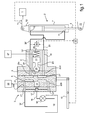
- a servocontrol is arranged to maneuver the blades 1 of a main rotor with a substantially vertical axis of a rotorcraft.
- the servocontrol conventionally combines at least one hydraulic cylinder 2 whose implementation is regulated by at least one hydraulic distributor 3,3 'comprising a distributor body 4 housing a main distribution member 5 and an emergency distribution member 6.
- the hydraulic cylinder 2 comprises at least one cylinder body 7,8 housing a rod 9 in axial mobility in the general direction of extension of the cylinder body 7,8.
- the cylinder body or bodies 7,8 are double-acting and comprise for this purpose a head passage 10 and a bottom passage 11 to allow a circulation of a fluid inside the cylinder body or bodies 7,8 .
- the fluid is conveyed under pressure to the cylinder body (s) 7,8 and is potentially admitted into the cylinder body (s) 7,8, either through the head passage 10 or through the bottom passage 11. Conversely, the fluid is discharged out of the cylinder body (s) 7,8 through the bottom passage 11 or through the head passage 10.
- the circulation of the fluid inside the cylinder body or bodies 7,8 causes a relative mobility between the cylinder body or bodies 7,8 and the rod 9 which is slidably mounted inside at least one body of cylinder 7.8 following two opposite directions of mobility.
- the relative mobility between the cylinder body or bodies 7,8 and the rod 9 is used to operate the blades 1.
- the cylinder body (s) 7, 8 and the rod (s) 9 of the hydraulic jack (s) 2 are each provided with an attachment member 12, 13 for their respective engagement on a chassis of the rotorcraft and or on an actuator 14 of the blades 1.
- the rod 9 is equipped with an attachment member 13 to the rotorcraft frame and the cylinder body 7 is equipped with an attachment member 12 to the actuating member 14 of the blades 1.
- rods 9 cooperating with respective cylinder bodies 7,8 are jointly equipped with a common fastening member 13 to the actuating member 14 of the blades 1.
- the cylinder bodies 7.8 are each equipped with a fastener 12 to the frame of the rotorcraft.
- the servo control comprises a hydraulic cylinder 2 comprising a single cylinder body 7.
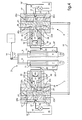
- the servocontrol comprises a hydraulic cylinder 2 comprising two actuator bodies 7,8 mounted in tandem and housing a common rod 9.
- the servocontrol comprises a hydraulic cylinder 2 comprising two cylinder bodies 7, 8 placed in parallel, the respective rods 9 of which are jointly operated by being connected to each other by means of the common fastening member 12 of which they are equipped.
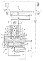
- fig.1 to fig.4 the regulation of the flow of fluid through at least one cylinder body 7.8 is placed under the control of a hydraulic distributor 3,3 'assigned to it.
- the control of the operation of at least one hydraulic distributor 3,3 ' is placed under the control of a control member 15 operable by a pilot of the rotorcraft, indifferently pilot human or autopilot.
- the control member 15 is engaged on the main distribution member 5 of at least one hydraulic distributor 3,3 'to regulate the flow of fluid between the at least one cylinder body 7,8 and a source of fluid 16.
- the distributor body 4 of a hydraulic distributor 3,3 'of the invention comprises ducts A 17,17' dedicated to the hydraulic junction between the hydraulic distributor 3,3 'and the source of fluid 16.
- a pipe, called A flow 18, conveys through a pump 16 'the pressurized fluid from the fluid source 16 to an inlet duct 17 of the distributor hydraulic 3,3 '.
- Another pipe, called return line 18 ', conveys the pressurized fluid from the exhaust ducts 17' of the hydraulic distributor 3, 3 'to the source of fluid 16.
- the distributor body 4 of a hydraulic distributor 3,3 'of the invention also comprises ducts B 19,19' dedicated to a hydraulic junction between the hydraulic distributor 3,3 'and a cylinder body 7,8 to which it is affected.
- the conduits B are in hydraulic communication via lines 20, 20 ', called lines B, respectively with the head passage 10 and the bottom passage 11 of the cylinder body 7, 8 to which the hydraulic distributor 3, 3' is affected.
- first pipe B said pipe B head 20 and a second pipe B, said bottom pipe B '20', the leading pipe B and said bottom pipe B 'being in fluid communication respectively with the head passage 10 and the bottom passage 11 of the cylinder body 7,8 to which the lines B are affected.
- the main distribution member 5 of a hydraulic distributor 3,3 ' is slidably mounted inside the emergency distribution member 6, itself slidably mounted in the distributor body 4.
- the main distribution member 5 frictionally drives the emergency distribution member 6 which slides inside. of the distributor body 4 to keep the hydraulic distributor 3,3 'in operation.
- the main distribution member 5 comprises first channels 21,21 'called channels A, dedicated to a circulation of the fluid through the hydraulic distributor 3,3' between the ducts A 17,17 'and the ducts B 19,19' .
- the channels A 21, 21 ' are formed by respective enclosures opening at the periphery of the main distribution member 5 towards the recess of the emergency distribution member 6 housing the actuator member. main distribution 5.
- the emergency distribution member 6 comprises second channels 22-22d (22,22a, 22b, 22c, 22d) called channels B.
- the channels B 22-22d are dedicated to a circulation of the fluid between the ducts A 17,17 'and the ducts B 19,19' via the channels A 21,21 '.
- the circulation of the fluid between the ducts A 17, 17 'and the ducts B 19, 19' is selectively obtained according to various respective positions of the main distribution member 5 operated by the control member 15.
- the emergency distribution member 6 In the event of jamming of the main distribution member 5, the emergency distribution member 6 is held in a predefined position inside the distributor body 4. For this purpose, the emergency distribution member 6 is blocked on the distributor body 4 via a spindle 23.
- the spindle 23 is axially movably mounted inside the distributor body 4 and cooperates by slidingly fitting with a cavity 24 formed in the spool member. emergency distribution 6.
- the axial mobility of the spindle 23 is oriented transversely, and more specifically orthogonally, with respect to the mobility axis of the emergency distribution member 6 so that the locking force of the emergency distribution member 6 on the distributor body 4 is optimized.
- the spindle 23 more particularly comprises a spherical shaped head 25 or similar conformation providing said interlocking sliding support of the head 25 inside the cavity 24.
- the spindle 23 is held in the engaged position by placing in close cooperation between the head 25 and the cavity 24 as represented on the fig.1 to fig.5 .
- the spindle 23 is held in the engaged position under the effect of a thrust exerted by means of elastic deformation 26 taking antagonistic supports against the distributor body 4 and against the spindle 23.
- Said antagonistic supports are applied axially according to the invention. general axis of extension and mobility of the pin 23 inside the distributor body 4.
- Such relative sliding between the head 25 and the cavity 24 is significant of a seizure of the main distribution member 5 inside the emergency distributor member 6 and is caused at a predetermined force threshold of relative mobility between the emergency distribution member 6 and the distributor body 4.
- Said force threshold is predetermined according to the frictional forces between the emergency distribution member 6 and the distributor body 4, according to the thrust force exerted against the pin 23 by the resilient deformation means 26 and according to the surface state and conformation of the sliding bearing surface of the head 25 against the cavity 24, said bearing surface being preferably spherical.
- the pin 23 is held in the engagement position inside the cavity 24 by means of elastic deformation 26 formed of a compression spring for example.
- elastic deformation means 26 formed by a leaf spring (s).
- a movement of the emergency distribution member 6 inside the distributor body 4 causes a relative sliding between the head 25 and the cavity 24 and is detected by detection means 28 which cause the implementation of the means maneuvering 27.
- the detection means 28 are for example means for detecting a relative mobility primer between the emergency distribution member 6 and the distributor body 4 under the effect of seizing the main distribution member 5 driving by friction the emergency distribution member 6.
- the operating means 27 are potentially any type of means able to move the pin 23, such as mechanical type, electromagnetic type, pneumatic type or chemical type.
- the cavity 24 is formed of the outlet of a channel 29, said channel C, forming a first fluid passage between any conduit A 17, 17 'or conduit B 19,19' and a chamber 30 formed in the distributor body 4.
- the pin 23 is provided with a piston 31 and said chamber 30 is a guide chamber sliding of the pin 23 to the release position, the sliding of the pin 23 being caused by the admission of the fluid under pressure inside the chamber 30 via the channel C 29, preferably via the channels A 21, 21 'to simplify the structural arrangement of the hydraulic distributor 3,3'.
- the spindle 23 is held in the engaged position by the elastically deformable means 26 formed by the leaf spring (s) applying an axial thrust against the spindle 23 in the direction of the emergency dispensing member 6.
- head 25 is maintained applied against the cavity 24 by closing the channel C 29.
- the emergency distribution member 6 is blocked by the cooperation by stitching between the head 25 and the cavity 24.
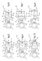
- the emergency dispensing member 6 tends to be slidably driven within the valve body 4 by the main dispensing member 5. As low as 1 amplitude of such a movement of the emergency distribution member 6, this movement causes a sliding of the head 25 inside the cavity 24 in an intermediate position of the pin 23.
- the head 25 In the intermediate position of the spindle 23, the head 25 is held engaged inside the cavity 24 while being partially released from the grip exerted by the cavity 24 on the spindle 23.
- the spindle 23 is slidably engaged with the spindle 23. inside the cavity 24 via the head 25, the emergency distribution member 6 is held in the intermediate position of the pin 23 partially immobilized on the distributor body 4. Such partial immobilization is considered as floating in because of the relative sliding caused between the cavity 24 and the head 25.
- the distributor body 4 comprises a fluid passage, said channel E 33, opening upstream of the piston 31 in the direction of movement of the pin 23 from the engagement position to the disengagement position.
- the channel E 33 is a connecting channel between the chamber 30 and the exhaust duct 17 ', to allow a possible escape of fluid from the channel C 29 in the engagement position of the pin 23 inside the the cavity 24. Such a possible escape of fluid can be induced by an undesirable source of leakage between the cavity 24 and the head 25.
- the fluid flowing inside the exhaust duct 17 ' is at a pressure lower than the pressure of the fluid flowing in the intake duct 17.
- a pressure difference is for example induced by venting the return line 18 'to the fluid source 16 or at least by pressurizing the discharge conduit A at a pressure lower than the fluid admitted under pressure to the hydraulic distributor 3.3 'by means of the pump 14'.
- the admission of the fluid into the chamber 30 through the channel E 33 provides a lubrication of the chamber 30 and avoids excessive pressure buildup in the chamber 30 upstream of the piston 31 in the direction of circulation of the fluid admitted to the interior of the chamber 30 from the channel C 29.
- D channels 32 are formed in the distributor body 4 between the chamber 30 and respectively each of the ducts A 17.17 'and ducts B 19.19'. In the engagement position of the pin 23 as illustrated on the fig.2 to fig.5 , the D channels 32 are closed by the piston 31 so that the admission of fluid inside the D 32 channels is inefficient.
- the D channels 32 open on the chamber 30 in the same common radial plane R.
- the D channels 32 in communication with the ducts A 17,17 'open on the chamber 30 in a first radial plane R1 and the channels D 32 in communication with the ducts B 19,19' open on the chamber 30 in a second radial plane R1.
- the first radial plane R1 is preferably placed upstream of the second radial plane R2 in the direction of flow of the fluid admitted inside the chamber 30 from the channel C 29.
- Each hydraulic distributor 3,3 ' is equipped with means for holding the spindle 23 in the release position, independently of a break in the implementation of the operating means 27.
- said holding means are formed by the leaf spring (s) 26.
- the leaf spring (s) 26 In the release position of the spindle 23 the leaf spring (s) 26 is pushed by the spindle 23 causing its deformation in a curvature inverse to its curvature initial in spindle engagement position 23. In this inverted curvature position, the leaf spring (s) exerts a pulling force on the spindle 23 in the direction opposite to the direction of the thrust it exerts on the spindle. 23 in the engagement position.
- said holding means are formed by an elastically deformable clip 34 formed on the body of 4, the clip 34 cooperating by interlocking with a housing 35 formed on the spindle 23.
- Such a restriction 36 does not prevent an escapement of the fluid admitted inappropriately inside the chamber 30 under the effect of a said source of leakage between the head 25 and the cavity 24.
- the restriction 36 makes it possible to to increase the load required for evacuation from the chamber 30 of the fluid admitted under pressure from the intake channel A to the chamber 30 through the channel E 33.
- the channels D 32 are placed in fluid communication with the chamber 30.
- the ducts A 17, 17 'and the ducts B 19, 19' are placed in fluid communication between they, with the effect of rendering inefficient the fluid pressure exerted on either side of the rod 9 cooperating with the cylinder body 7,8 assigned to the hydraulic distributor 3,3 '.
- mechanical connection means 37 place under direct mechanical dependence the control member 15 and the actuator 14 of the blades 1, so that the blades 1 can be directly operated by the operating member 15 avoiding operation faulty servocontrol.
- Such mechanical connection means 37 are potentially implemented by the human pilot of the rotorcraft or are spontaneously implemented while being placed under the control of a sensor 38 of the inefficiency of the fluid pressure exerted on the part and Another of the rod 9.
- a sensor 38 is for example formed by means for measuring the pressure of the fluid flowing through the pipes B 20,20 '.
- the mobility modalities of the spindle illustrated on the fig.5 to fig.10 in the context of maneuvering means of the hydraulic type using the fluid admitted under pressure inside the hydraulic distributor 3,3 ', are transposable without special effort by substitution to a hydraulic distributor illustrated on the fig.1 wherein the actuating means are of any other type.
- the hydraulic distributors 3,3 'illustrated for example in the figures are of the drawer type, the main distribution member 5 and the emergency distribution member 6 being slidably mounted inside the distributor body 4. It is however, to consider that the rules set forth by the present invention are transposable without any particular effort to rotary type hydraulic distributors 3,3 ', in which the main distribution member 5 and the emergency distribution member 6 are mounted in mobility rotating inside the dispenser body 4.
- the general axis of extension and mobility of the spindle 5, and corollary the direction of thrust and / or traction exerted by the elastically deformable means 26 on the spindle 23, are oriented transversely to the axis of mobility of the main distribution member 5 and the emergency distribution member 6.
- Such an arrangement of the mobility of the spindle 23 allows easy application of the invention to a hydraulic dispenser of any type with a drawer or rotary type. Indeed, the sliding or rotating mobility modes of the main distribution member 5 and the emergency distribution member 6 inside the distributor body 4 of the hydraulic distributor 3,3 'have no effect on the conditions implementation and mobility of the spindle 23 to alternatively implement or inhibit the locking by broaching between the emergency distribution member 6 and the distributor body 4.
Landscapes
- Engineering & Computer Science (AREA)
- General Engineering & Computer Science (AREA)
- Mechanical Engineering (AREA)
- Aviation & Aerospace Engineering (AREA)
- Physics & Mathematics (AREA)
- Fluid Mechanics (AREA)
- Automation & Control Theory (AREA)
- Chemical & Material Sciences (AREA)
- Analytical Chemistry (AREA)
- Fluid-Pressure Circuits (AREA)
- Actuator (AREA)
Claims (22)
- Hydraulischer Doppelverteiler (3, 3') einer Servosteuerung zum Steuern von Blättern (1) eines Rotors eines Drehflügelflugzeugs, wobei der hydraulische Verteiler (3, 3') aufweist:-) einen Körper, Verteilerkörper (4) genannt, des hydraulischen Verteilers (3, 3') mit ersten Leitungen, Leitungen A (17, 17') genannt, die dazu bestimmt sind, eine hydraulische Verbindung zwischen dem hydraulischen Verteiler (3, 3') und einer Druckfluidquelle (16) herzustellen, wobei die Leitungen A (17, 17') mindestens eine Einlassleitung, genannt Einlassleitung A (17), die für einen Einlass des Fluids von außerhalb des Verteilers zum Inneren des hydraulischen Verteilers (3, 3') sorgt, und mindestens eine Auslassleitung, genannt Auslassleitung A (17'), die für einen Auslass des Fluids aus dem hydraulischen Verteiler (3, 3') sorgt, aufweisen, wobei der Verteilerkörper (4) zweite Leitungen, genannt Leitungen B (19, 19') aufweist, die dazu bestimmt sind, eine hydraulische Verbindung zwischen dem hydraulischen Verteiler (3, 3') und einem Körper, genannt Kolben-Zylinder-Einheits-Körper (7, 8), einer hydraulischen Kolben-Zylinder-Einheit (2) der Servosteuerung herzustellen, wobei die Leitungen B (19, 19') ein Paar von Leitungen B aufweisen, die für eine Zirkulation des Fluids zwischen dem Inneren und dem Äußeren des hydraulischen Verteilers (3, 3') sorgen,-) ein Hauptverteilungsorgan (5), das beweglich im Inneren des Verteilerkörpers (4) montiert ist, und das durch ein Steuerorgan (15) manövrierbar ist, wobei das Hauptverteilungsorgan (5) erste Kanäle, genannt Kanäle A (21), die für eine Zirkulation des Fluids durch den hydraulischen Verteiler (3, 3') zwischen den Leitungen A (17, 17') und den Leitungen B (19, 19') sorgen, aufweist, wobei die Einlassleitung A (17) und die Auslassleitung A (17') über Kanäle A (21) wahlweise in Fluidverbindung stehen mit der einen oder der anderen der Leitungen B (19, 19'), je nach den jeweiligen Stellungen des Hauptverteilungsorgans (5) im Inneren des Verteilerkörpers (4),-) ein Hilfsverteilungsorgan (6), das zwischen dem Verteilerkörper (4) und dem Hauptverteilungsorgan (5) angeordnet ist, wobei das Hilfsverteilungsorgan (6) das Hauptverteilungsorgan (5) beweglich lagert, und beweglich im Inneren des Verteilerkörpers (4) montiert ist, wobei das Hilfsverteilungsorgan (6) zweite Kanäle bildet, Kanäle B (22, 22d) genannt, die selektiv für eine Zirkulation des Fluids zwischen einerseits den Kanälen A (21, 21') und andererseits den Leitungen A (17, 17') und den Leitungen B (19, 19') bestimmt sind, gemäß den jeweiligen Positionen des Hauptverteilungsorgans (5),-) Mittel zum Positionieren des Hilfsverteilungsorgans (6) in einer vordefinierten Position im Inneren des Verteilerkörpers (5), wobei in dieser vordefinierten Position des Hilfsverteilungsorgans (6) die Kanäle A (17, 17') und die Kanäle B (19, 19') jeweils zu zweit in Fluidverbindung stehen, wobei die Positionierungsmittel mindestens elastisch verformbare Mittel (26) in Betrieb setzen, die gegen den Verteilerkörper (4) andrücken, wobei eine Beweglichkeit des Hilfsverteilungsorgans (6) im Inneren des Verteilerkörpers (4) zusammen mit dem Hauptverteilungsorgan (5) zugelassen wird durch den Effekt eines Antriebs durch Reibung des Hilfsverteilungsorgans (6) durch das Hauptverteilungsorgan (5) im Fall eines Festfressens im Inneren des Hilfsverteilungsorgans (6) gegenüber einem Druck, der von den elastisch verformbaren Mitteln (26) ausgeübt wird,
dadurch gekennzeichnet, dass die Positionierungsmittel Mittel zum Blockieren des Hilfsverteilungsorgans (6) auf dem Verteilerkörper (4) durch einen Stift (23) sind, der beweglich auf dem Verteilerkörper (4) montiert ist und mit einer Ausnehmung (24) des Hilfsverteilungsorgans (6) durch gleitendes Einfügen zusammenwirkt, wobei der Stift (23) beweglich ist zwischen einer Eingriffsstellung, in der ein Kopf (25) des Stiftes (23) in der Ausnehmung (24) gelagert ist, unter Einwirkung des Drucks, der gegen den Stift (23) durch die elastisch verformbaren Mittel (26) ausgeübt wird, und einer entkoppelten Position, in der der Kopf (25) vollständig aus der Ausnehmung (24) durch Manövriermittel (27) des Stifts (23) entgegen dem Druck, der gegen den Stift (23) durch die elastisch verformbaren Mittel (26) ausgeübt wird, gelöst ist, wobei die Inbetriebsetzung der Manövriermittel (27) von einer relativen Beweglichkeit zwischen dem Hilfsverteilungsorgan und dem Verteilerkörper abhängig gemacht wird, der eine mindestens teilweise Befreiung der Ausnehmung (24) durch Gleiten des Kopfes (25) im Inneren der Ausnehmung (24) ermöglicht. - Hydraulischer Verteiler nach Anspruch 1,
dadurch gekennzeichnet, dass die Manövriermittel (27) des Stiftes (23) Fluidschubmittel des Stiftes (23) sind, die mit einem Zylinder versehen sind, der mit dem Fluid beaufschlagt ist, welches unter Druck in das Innere des hydraulischen Verteilers (3, 3') eingelassen wird. - Hydraulischer Verteiler nach Anspruch 2,
dadurch gekennzeichnet, dass der Stift (23) beweglich in einer Kammer (30) des Verteilerkörpers (4) gelagert ist und als Verschluss-Düsennadel eines ersten Fluidddurchgangs, genannt Kanal C (29), ausgebildet ist, der in der Kammer (30) durch den Hohlraum (24) mündet und in Fluidverbindung mit einer beliebigen der Leitungen A (17, 17') und der Leitungen B (19, 19') steht, wobei eine zumindest teilweise Öffnung des Hohlraums (24) das Einlassen des Fluids, welches aus dem Kanal C (29) stammt, in das Innere der Kammer (30) erlaubt. - Hydraulischer Verteiler nach Anspruch 3,
dadurch gekennzeichnet, dass der Kanal C (29) in Fluidverbindung mit der Einlassleitung A (17) steht. - Hydraulischer Verteiler nach einem der Ansprüche 1 bis 4,
dadurch gekennzeichnet, dass der hydraulische Verteiler (3, 3') Mittel zur Fluidverbindung zwischen der Gruppe der Leitungen A (17, 17') und der der Leitungen B (19, 19') in Öffnungsstellung des Stiftes (23) aufweist. - Hydraulischer Verteiler nach Anspruch 5,
dadurch gekennzeichnet, dass der Verteilerkörper (4) zweite Flu-iddurchgänge, genannt Kanäle D (32) aufweist, wobei die Kanäle D (32) Fluiddurchgänge sind für einen ersten Kanal D (32) zwischen der Kammer (30) und der Einlassleitung A (17) für einen zweiten Kanal D (32) zwischen der Kammer (30) und der Auslassleitung A (17') bzw. für einen dritten Kanal D (32) zwischen der Kammer (30) und einer beliebigen der Leitungen B (19, 19'), und für einen vierten Kanal D (32) zwischen der Kammer (30) und dem anderen Kanal B (19, 19'), wobei die Mündungen in der Kammer (30) der Kanäle D (32) durch den Kolben (31) in Eingriffsposition des Stiftes (23) gemeinsam verschlossen sind, und in der Lösungsstellung des Stiftes (23) von dem Kolben (31) befreit sind. - Hydraulischer Verteiler nach Anspruch 6,
dadurch gekennzeichnet, dass die Kanäle D (32) in der Kammer (30) in derselben radialen Ebene (R), betrachtet bezüglich der Axialrichtung der Bewegung des Stiftes (23) im Inneren der Kammer (30), liegen, wobei das fluidmäßige Verbinden der Gruppe der Leitungen A (17, 17') untereinander und der Leitungen B (19, 19') gleichzeitig erfolgt. - Hydraulischer Verbinder nach Anspruch 6,
dadurch gekennzeichnet, dass die Kanäle D (32) in der Kammer (30) in unterschiedlichen radialen Ebenen (R1, R2) bezüglich der Bewegungsrichtung des Stiftes (23) im Inneren der Kammer (30) münden, wobei das fluidmäßige Verbinden der Leitungen A (17, 17') und der Leitungen B (19, 19') untereinander schrittweite erfolgt. - Hydraulischer Verteiler nach einem der Ansprüche 3 bis 8,
dadurch gekennzeichnet, dass die Kammer (30) in Fluidverbindung mit der Auslassleitung A (17') über einen dritten Fluiddurchgang, Kanal E (33) genannt, steht, wobei der Kanal E (33) an einer beliebigen Stelle des Stiftes (23) über den Kolben (31) in Bewegungsrichtung des Stiftes (23) von der Eingriffsstellung zur Entkopplungsstellung mündet. - Hydraulischer Verteiler nach Anspruch 9,
dadurch gekennzeichnet, dass der Kanal E (33) eine Querschnittsverjüngung (36) aufweist. - Hydraulischer Verteiler nach einem der Ansprüche 1 bis 10,
dadurch gekennzeichnet, dass der hydraulische Verteiler (3, 3') Mittel zum Halten des Stiftes (23) in einer Entkopplungsstellung aufweist, unabhängig von einer Unterbrechung der Betätigung der Manövriermittel (27). - Hydraulischer Verteiler nach Anspruch 11,
dadurch gekennzeichnet, dass die Haltemittel gebildet werden durch die elastisch verformbaren Mittel (26), bestehend aus einer Feder mit mindestens einem Federblatt, wobei die Feder mit Federblatt bzw. mit Federblättern am Verteilerkörper (4) befestigt ist und in zwei Richtungen mit dem Stift (23) in Eingriff steht, wobei die Feder mit Federblatt bzw. mit Federblättern einen Druck gegen den Stift (23) in der Eingriffsstellung ausübt und eine Zugbeanspruchung des Stiftes (23) in entkoppelter Stellung, als Folge ihrer Verformung, hervorgerufen durch den Durchgang des Stiftes (23) in entkoppelter Stellung ausübt. - Hydraulischer Verteiler nach Anspruch 11,
dadurch gekennzeichnet, dass die Haltemittel vom Typ einer elastischen Muffenverbindung sind und eine elastisch verformbare Klammer (34) aufweisen, die mit einem Lager (35) zusammenwirkt, wobei die Klammer (34) und das Lager (35) jeweils unterschiedslos auf dem Verteilerkörper oder dem Stift (23) angeordnet sind. - Hydraulischer Verteiler nach einem der Ansprüche 1 bis 13,
dadurch gekennzeichnet, dass der hydraulische Verteiler (3, 3') vom Schiebertyp ist, wobei das Hauptverteilungsorgan (5) und das Hilfsverteilungsorgan (6) translatorisch beweglich im Inneren des Verteilerkörpers (4) montiert sind. - Hydraulischer Verteiler nach einem der Ansprüche 1 bis 13,
dadurch gekennzeichnet, dass der hydraulische Verteiler (3, 3') vom drehbaren Typ ist, wobei das Hauptverteilungsorgan (5) und das Hilfsverteilungsorgan (6) schwenkbeweglich im Inneren des Verteilerkörpers (4) montiert sind. - Hydraulischer Verteiler nach einem der Ansprüche 1 bis 15,
dadurch gekennzeichnet, dass die Auflagefläche des Kopfes (25) des Stiftes (23) im Inneren des Hohlraums (24) eine kreisförmige Fläche ist. - Hydraulischer Verteiler nach Anspruch 1,
dadurch gekennzeichnet, dass der Betrieb der Manövriermittel (27) abhängig gemacht wird von Erfassungsmitteln (28) einer Relativbewegung zwischen dem Hauptverteilungsorgan und dem Hilfsverteilungsorgan (6). - Servosteuerung der Betätigung von Blättern (1) eines Rotors eines Drehflügelflugzeugs, wobei die Servosteuerung mindestens eine hydraulische Kolben-Zylinder-Einheit (2) aufweist mit mindestens einem Körper (7, 8) einer doppelt wirkenden Kolben-Zylinder-Einheit und mit mindestens einem hydraulischen Verteiler (3, 3') nach einem der Ansprüche 1-17.
- Servosteuerung nach Anspruch 18, wobei die Servosteuerung mindestens eine hydraulische Kolben-Zylinder-Einheit (2) mit mehreren Körpern (7, 8) einer Kolben-Zylinder-Einheit mit doppelter Wirkung aufweist, wobei jeder der Körper (7, 8) der Kolben-Zylinder-Einheit von einem ihm zugeordneten hydraulischen Verteiler (3, 3') mit Fluid gespeist wird.
- Servosteuerung nach Anspruch 19, wobei die Servosteuerung mindestens eine hydraulische Kolben-Zylinder-Einheit (2) mit doppeltem Körper (7, 8) der doppelt wirkenden Kolben-Zylinder-Einheit aufweist,
dadurch gekennzeichnet, dass-) jeder der Körper (7, 8) der hydraulischen Kolben-Zylinder-Einheit (2) in Fluidverbindung mit einem hydraulischen Verteiler (3, 3') steht, der ihm zugeordnet ist, wobei die Leitungen B (19, 19') eines jeden hydraulischen Verteilers (3, 3') in Fluidverbindung mit dem jeweiligen Körper (7, 8) der Kolben-Zylinder-Einheit stehen,-) eine beliebige der Leitungen B (19, 19') eines ersten hydraulischen Verteilers (3, 3') in Fluidverbindung mit einem ersten Durchgang des Kopfes (10) eines ersten Körpers der Kolben-Zylinder-Einheit steht, und die andere der Leitungen B (19, 19') des ersten hydraulischen Verteilers (3, 3') in Fluidverbindung mit einem ersten Durchgang (11) am Boden des ersten Körpers der Kolben-Zylinder-Einheit steht,-) eine beliebige der Leitungen B (19, 19') eines zweiten hydraulischen Verteilers (3, 3') in Fluidverbindung mit einem zweiten Durchgang des Kopfes (10) eines zweiten Körpers (7, 8) der Kolben-Zylinder-Einheit steht, und die andere der Leitungen B (19, 19') des zweiten hydraulischen Verteilers (3, 3') in Fluidverbindung mit einem zweiten Durchgang (11) am Boden des zweiten Körpers (7, 8) der Kolben-Zylinder-Einheit steht,-) die Hauptverteilungsorgane (5) eines jeden hydraulischen Verteilers (3, 3') gemeinsam in Eingriff mit einem gemeinsamen Manövrierorgan (15) stehen, dessen Betätigung die Fluidverteilung durch die beiden hydraulischen Verteiler (3, 3') regelt. - Servosteuerung nach Anspruch 20, bei der die Körper (7, 8) der hydraulischen Kolben-Zylinder-Einheit in Tandem-Anordnung angeordnet sind, und zusammen eine gemeinsame Stange (9) beherbergen.
- Servosteuerung nach Anspruch 20, bei der die Körper (7, 8) der hydraulischen Kolben-Zylinder-Einheit (2) parallel zueinander angeordnet sind, wobei die Körper (7, 8) der Kolben-Zylinder-Einheit Stangen (9) beherbergen, die jeweils mechanisch miteinander verbunden sind.
Applications Claiming Priority (1)
| Application Number | Priority Date | Filing Date | Title |
|---|---|---|---|
| FR1301144A FR3005632B1 (fr) | 2013-05-17 | 2013-05-17 | Distributeur hydraulique double d'une servocommande de manoeuvre des pales d'un rotor de giravion |
Publications (2)
| Publication Number | Publication Date |
|---|---|
| EP2803572A1 EP2803572A1 (de) | 2014-11-19 |
| EP2803572B1 true EP2803572B1 (de) | 2015-10-28 |
Family
ID=48979815
Family Applications (1)
| Application Number | Title | Priority Date | Filing Date |
|---|---|---|---|
| EP14001385.5A Active EP2803572B1 (de) | 2013-05-17 | 2014-04-16 | Hydraulischer Doppelverteiler einer Servosteuerung zum Steuern der Blätter des Rotors eines Drehflügelflugzeugs |
Country Status (3)
| Country | Link |
|---|---|
| US (1) | US9624946B2 (de) |
| EP (1) | EP2803572B1 (de) |
| FR (1) | FR3005632B1 (de) |
Families Citing this family (3)
| Publication number | Priority date | Publication date | Assignee | Title |
|---|---|---|---|---|
| FR3054199B1 (fr) * | 2016-07-25 | 2019-08-02 | Airbus Operations | Systeme d’actionnement d’une surface de controle d’un aeronef. |
| FR3054619B1 (fr) * | 2016-07-26 | 2018-11-23 | Airbus Helicopters | Servocommande a stabilisation integree au distributeur pour les commandes de vol d'un aeronef |
| EP3763621B1 (de) | 2019-07-12 | 2024-08-28 | Ratier-Figeac SAS | Hydraulisches betätigungssystem |
Family Cites Families (5)
| Publication number | Priority date | Publication date | Assignee | Title |
|---|---|---|---|---|
| US3529514A (en) * | 1969-03-25 | 1970-09-22 | United Aircraft Corp | Redundant servomechanism with bypass provisions |
| US4128047A (en) * | 1975-08-14 | 1978-12-05 | Textron Inc. | Actuator with locking valves |
| DE2855636C2 (de) * | 1978-12-22 | 1985-08-08 | Messerschmitt-Bölkow-Blohm GmbH, 8000 München | Servosteuerventil |
| US6981439B2 (en) * | 2003-08-22 | 2006-01-03 | Hr Textron, Inc. | Redundant flow control for hydraulic actuator systems |
| FR2916492B1 (fr) | 2007-05-24 | 2009-07-17 | Eurocopter France | Distributeur hydraulique muni d'un dispositif de detection de grippage. |
-
2013
- 2013-05-17 FR FR1301144A patent/FR3005632B1/fr not_active Expired - Fee Related
-
2014
- 2014-04-16 EP EP14001385.5A patent/EP2803572B1/de active Active
- 2014-05-14 US US14/277,422 patent/US9624946B2/en not_active Expired - Fee Related
Also Published As
| Publication number | Publication date |
|---|---|
| US9624946B2 (en) | 2017-04-18 |
| US20150176612A1 (en) | 2015-06-25 |
| FR3005632B1 (fr) | 2015-05-29 |
| EP2803572A1 (de) | 2014-11-19 |
| FR3005632A1 (fr) | 2014-11-21 |
Similar Documents
| Publication | Publication Date | Title |
|---|---|---|
| US8277182B2 (en) | Remote pitch controller for a variable pitch propeller | |
| EP2930375B1 (de) | Ausgleichsschieber der Flüssigkeitszufuhr zu den Zylinderkörpern einer Servosteuerung, die die Blätter des Rotors eines Drehflügelflugzeugs steuern | |
| US7954318B2 (en) | PTM self-bleed/failsafe open system for FWD and RWD | |
| CN110374944B (zh) | 具有双滑阀的飞行器液压系统及使用方法 | |
| US20080173763A1 (en) | Fuel jettison system | |
| US10458557B2 (en) | Hydraulic actuator force fight mitigation mechanism | |
| CN104612855A (zh) | 锁定推力反向器的风扇喷嘴驱动系统 | |
| EP2803572A1 (de) | Hydraulischer Doppelverteiler einer Servosteuerung zum Steuern der Blätter des Rotors eines Drehflügelflugzeugs | |
| FR2992696A1 (fr) | Distributeur hydraulique, dispositif de reglage du pas de pales, aeronef muni d'un tel distributeur hydraulique | |
| EP2630357B1 (de) | Betätigungssystem für ein antriebsaggregat eines flugzeugs | |
| US9284042B2 (en) | System for controlling pitch variation of the blades of a propeller, a propeller, and an aircraft | |
| US20090180883A1 (en) | Hydraulically controlled variable pitch propeller | |
| EP3042847B1 (de) | Servosteuerung und luftfahrzeug, das mit einer solchen servosteuerung ausgestattet ist | |
| EP2565121B1 (de) | Kabinendruckablassventil mit Schubrückgewinnung und Verfahren zur RAM-Luftgewinnung | |
| CA2580276C (en) | Mechanical flight control auxiliary power assist system | |
| US10351264B2 (en) | Anti-stall hydraulic pump for a thrust vector control system | |
| US9404593B2 (en) | Vent valve | |
| CN110937104B (zh) | 具有同步构件的分布式线性液压抬高致动系统 | |
| EP2293982B1 (de) | Treibstoffablasssystem | |
| EP3374262B1 (de) | Rotorblattstrukturen | |
| EP3181906B1 (de) | Hydraulikpumpensysteme | |
| US10753419B2 (en) | Hydraulic damping systems | |
| EP4306810A1 (de) | Hauptregelventil mit integriertem hydraulischem scas | |
| FR2996602A1 (fr) | Dispositif d'actionnement incluant un dispositif de verrouillage primaire |
Legal Events
| Date | Code | Title | Description |
|---|---|---|---|
| PUAI | Public reference made under article 153(3) epc to a published international application that has entered the european phase |
Free format text: ORIGINAL CODE: 0009012 |
|
| 17P | Request for examination filed |
Effective date: 20140416 |
|
| AK | Designated contracting states |
Kind code of ref document: A1 Designated state(s): AL AT BE BG CH CY CZ DE DK EE ES FI FR GB GR HR HU IE IS IT LI LT LU LV MC MK MT NL NO PL PT RO RS SE SI SK SM TR |
|
| AX | Request for extension of the european patent |
Extension state: BA ME |
|
| R17P | Request for examination filed (corrected) |
Effective date: 20150106 |
|
| RBV | Designated contracting states (corrected) |
Designated state(s): AL AT BE BG CH CY CZ DE DK EE ES FI FR GB GR HR HU IE IS IT LI LT LU LV MC MK MT NL NO PL PT RO RS SE SI SK SM TR |
|
| GRAP | Despatch of communication of intention to grant a patent |
Free format text: ORIGINAL CODE: EPIDOSNIGR1 |
|
| RIC1 | Information provided on ipc code assigned before grant |
Ipc: F15B 13/04 20060101ALI20150519BHEP Ipc: B64C 27/64 20060101ALI20150519BHEP Ipc: F15B 20/00 20060101ALI20150519BHEP Ipc: B64C 27/58 20060101AFI20150519BHEP |
|
| INTG | Intention to grant announced |
Effective date: 20150617 |
|
| GRAS | Grant fee paid |
Free format text: ORIGINAL CODE: EPIDOSNIGR3 |
|
| GRAA | (expected) grant |
Free format text: ORIGINAL CODE: 0009210 |
|
| AK | Designated contracting states |
Kind code of ref document: B1 Designated state(s): AL AT BE BG CH CY CZ DE DK EE ES FI FR GB GR HR HU IE IS IT LI LT LU LV MC MK MT NL NO PL PT RO RS SE SI SK SM TR |
|
| REG | Reference to a national code |
Ref country code: GB Ref legal event code: FG4D Free format text: NOT ENGLISH |
|
| REG | Reference to a national code |
Ref country code: CH Ref legal event code: EP |
|
| REG | Reference to a national code |
Ref country code: AT Ref legal event code: REF Ref document number: 757778 Country of ref document: AT Kind code of ref document: T Effective date: 20151115 |
|
| REG | Reference to a national code |
Ref country code: IE Ref legal event code: FG4D Free format text: LANGUAGE OF EP DOCUMENT: FRENCH |
|
| REG | Reference to a national code |
Ref country code: DE Ref legal event code: R096 Ref document number: 602014000368 Country of ref document: DE |
|
| REG | Reference to a national code |
Ref country code: LT Ref legal event code: MG4D |
|
| REG | Reference to a national code |
Ref country code: NL Ref legal event code: MP Effective date: 20151028 |
|
| REG | Reference to a national code |
Ref country code: AT Ref legal event code: MK05 Ref document number: 757778 Country of ref document: AT Kind code of ref document: T Effective date: 20151028 |
|
| REG | Reference to a national code |
Ref country code: FR Ref legal event code: PLFP Year of fee payment: 3 |
|
| PG25 | Lapsed in a contracting state [announced via postgrant information from national office to epo] |
Ref country code: ES Free format text: LAPSE BECAUSE OF FAILURE TO SUBMIT A TRANSLATION OF THE DESCRIPTION OR TO PAY THE FEE WITHIN THE PRESCRIBED TIME-LIMIT Effective date: 20151028 Ref country code: LT Free format text: LAPSE BECAUSE OF FAILURE TO SUBMIT A TRANSLATION OF THE DESCRIPTION OR TO PAY THE FEE WITHIN THE PRESCRIBED TIME-LIMIT Effective date: 20151028 Ref country code: NL Free format text: LAPSE BECAUSE OF FAILURE TO SUBMIT A TRANSLATION OF THE DESCRIPTION OR TO PAY THE FEE WITHIN THE PRESCRIBED TIME-LIMIT Effective date: 20151028 Ref country code: IS Free format text: LAPSE BECAUSE OF FAILURE TO SUBMIT A TRANSLATION OF THE DESCRIPTION OR TO PAY THE FEE WITHIN THE PRESCRIBED TIME-LIMIT Effective date: 20160228 Ref country code: HR Free format text: LAPSE BECAUSE OF FAILURE TO SUBMIT A TRANSLATION OF THE DESCRIPTION OR TO PAY THE FEE WITHIN THE PRESCRIBED TIME-LIMIT Effective date: 20151028 Ref country code: NO Free format text: LAPSE BECAUSE OF FAILURE TO SUBMIT A TRANSLATION OF THE DESCRIPTION OR TO PAY THE FEE WITHIN THE PRESCRIBED TIME-LIMIT Effective date: 20160128 |
|
| PG25 | Lapsed in a contracting state [announced via postgrant information from national office to epo] |
Ref country code: PL Free format text: LAPSE BECAUSE OF FAILURE TO SUBMIT A TRANSLATION OF THE DESCRIPTION OR TO PAY THE FEE WITHIN THE PRESCRIBED TIME-LIMIT Effective date: 20151028 Ref country code: PT Free format text: LAPSE BECAUSE OF FAILURE TO SUBMIT A TRANSLATION OF THE DESCRIPTION OR TO PAY THE FEE WITHIN THE PRESCRIBED TIME-LIMIT Effective date: 20160229 Ref country code: GR Free format text: LAPSE BECAUSE OF FAILURE TO SUBMIT A TRANSLATION OF THE DESCRIPTION OR TO PAY THE FEE WITHIN THE PRESCRIBED TIME-LIMIT Effective date: 20160129 Ref country code: FI Free format text: LAPSE BECAUSE OF FAILURE TO SUBMIT A TRANSLATION OF THE DESCRIPTION OR TO PAY THE FEE WITHIN THE PRESCRIBED TIME-LIMIT Effective date: 20151028 Ref country code: SE Free format text: LAPSE BECAUSE OF FAILURE TO SUBMIT A TRANSLATION OF THE DESCRIPTION OR TO PAY THE FEE WITHIN THE PRESCRIBED TIME-LIMIT Effective date: 20151028 Ref country code: RS Free format text: LAPSE BECAUSE OF FAILURE TO SUBMIT A TRANSLATION OF THE DESCRIPTION OR TO PAY THE FEE WITHIN THE PRESCRIBED TIME-LIMIT Effective date: 20151028 Ref country code: AT Free format text: LAPSE BECAUSE OF FAILURE TO SUBMIT A TRANSLATION OF THE DESCRIPTION OR TO PAY THE FEE WITHIN THE PRESCRIBED TIME-LIMIT Effective date: 20151028 Ref country code: LV Free format text: LAPSE BECAUSE OF FAILURE TO SUBMIT A TRANSLATION OF THE DESCRIPTION OR TO PAY THE FEE WITHIN THE PRESCRIBED TIME-LIMIT Effective date: 20151028 |
|
| PG25 | Lapsed in a contracting state [announced via postgrant information from national office to epo] |
Ref country code: CZ Free format text: LAPSE BECAUSE OF FAILURE TO SUBMIT A TRANSLATION OF THE DESCRIPTION OR TO PAY THE FEE WITHIN THE PRESCRIBED TIME-LIMIT Effective date: 20151028 |
|
| REG | Reference to a national code |
Ref country code: DE Ref legal event code: R097 Ref document number: 602014000368 Country of ref document: DE |
|
| PG25 | Lapsed in a contracting state [announced via postgrant information from national office to epo] |
Ref country code: DK Free format text: LAPSE BECAUSE OF FAILURE TO SUBMIT A TRANSLATION OF THE DESCRIPTION OR TO PAY THE FEE WITHIN THE PRESCRIBED TIME-LIMIT Effective date: 20151028 Ref country code: EE Free format text: LAPSE BECAUSE OF FAILURE TO SUBMIT A TRANSLATION OF THE DESCRIPTION OR TO PAY THE FEE WITHIN THE PRESCRIBED TIME-LIMIT Effective date: 20151028 Ref country code: SK Free format text: LAPSE BECAUSE OF FAILURE TO SUBMIT A TRANSLATION OF THE DESCRIPTION OR TO PAY THE FEE WITHIN THE PRESCRIBED TIME-LIMIT Effective date: 20151028 Ref country code: BE Free format text: LAPSE BECAUSE OF NON-PAYMENT OF DUE FEES Effective date: 20160430 Ref country code: RO Free format text: LAPSE BECAUSE OF FAILURE TO SUBMIT A TRANSLATION OF THE DESCRIPTION OR TO PAY THE FEE WITHIN THE PRESCRIBED TIME-LIMIT Effective date: 20151028 Ref country code: SM Free format text: LAPSE BECAUSE OF FAILURE TO SUBMIT A TRANSLATION OF THE DESCRIPTION OR TO PAY THE FEE WITHIN THE PRESCRIBED TIME-LIMIT Effective date: 20151028 |
|
| PLBE | No opposition filed within time limit |
Free format text: ORIGINAL CODE: 0009261 |
|
| STAA | Information on the status of an ep patent application or granted ep patent |
Free format text: STATUS: NO OPPOSITION FILED WITHIN TIME LIMIT |
|
| 26N | No opposition filed |
Effective date: 20160729 |
|
| REG | Reference to a national code |
Ref country code: DE Ref legal event code: R119 Ref document number: 602014000368 Country of ref document: DE |
|
| PG25 | Lapsed in a contracting state [announced via postgrant information from national office to epo] |
Ref country code: SI Free format text: LAPSE BECAUSE OF FAILURE TO SUBMIT A TRANSLATION OF THE DESCRIPTION OR TO PAY THE FEE WITHIN THE PRESCRIBED TIME-LIMIT Effective date: 20151028 |
|
| PG25 | Lapsed in a contracting state [announced via postgrant information from national office to epo] |
Ref country code: LU Free format text: LAPSE BECAUSE OF FAILURE TO SUBMIT A TRANSLATION OF THE DESCRIPTION OR TO PAY THE FEE WITHIN THE PRESCRIBED TIME-LIMIT Effective date: 20160416 |
|
| REG | Reference to a national code |
Ref country code: IE Ref legal event code: MM4A |
|
| PG25 | Lapsed in a contracting state [announced via postgrant information from national office to epo] |
Ref country code: DE Free format text: LAPSE BECAUSE OF NON-PAYMENT OF DUE FEES Effective date: 20161101 |
|
| REG | Reference to a national code |
Ref country code: FR Ref legal event code: PLFP Year of fee payment: 4 |
|
| PG25 | Lapsed in a contracting state [announced via postgrant information from national office to epo] |
Ref country code: IE Free format text: LAPSE BECAUSE OF NON-PAYMENT OF DUE FEES Effective date: 20160416 |
|
| REG | Reference to a national code |
Ref country code: CH Ref legal event code: PL |
|
| PG25 | Lapsed in a contracting state [announced via postgrant information from national office to epo] |
Ref country code: LI Free format text: LAPSE BECAUSE OF NON-PAYMENT OF DUE FEES Effective date: 20170430 Ref country code: CH Free format text: LAPSE BECAUSE OF NON-PAYMENT OF DUE FEES Effective date: 20170430 |
|
| REG | Reference to a national code |
Ref country code: FR Ref legal event code: PLFP Year of fee payment: 5 |
|
| PG25 | Lapsed in a contracting state [announced via postgrant information from national office to epo] |
Ref country code: HU Free format text: LAPSE BECAUSE OF FAILURE TO SUBMIT A TRANSLATION OF THE DESCRIPTION OR TO PAY THE FEE WITHIN THE PRESCRIBED TIME-LIMIT; INVALID AB INITIO Effective date: 20140416 |
|
| PG25 | Lapsed in a contracting state [announced via postgrant information from national office to epo] |
Ref country code: CY Free format text: LAPSE BECAUSE OF FAILURE TO SUBMIT A TRANSLATION OF THE DESCRIPTION OR TO PAY THE FEE WITHIN THE PRESCRIBED TIME-LIMIT Effective date: 20151028 Ref country code: MT Free format text: LAPSE BECAUSE OF FAILURE TO SUBMIT A TRANSLATION OF THE DESCRIPTION OR TO PAY THE FEE WITHIN THE PRESCRIBED TIME-LIMIT Effective date: 20151028 Ref country code: MC Free format text: LAPSE BECAUSE OF FAILURE TO SUBMIT A TRANSLATION OF THE DESCRIPTION OR TO PAY THE FEE WITHIN THE PRESCRIBED TIME-LIMIT Effective date: 20151028 Ref country code: MK Free format text: LAPSE BECAUSE OF FAILURE TO SUBMIT A TRANSLATION OF THE DESCRIPTION OR TO PAY THE FEE WITHIN THE PRESCRIBED TIME-LIMIT Effective date: 20151028 |
|
| PG25 | Lapsed in a contracting state [announced via postgrant information from national office to epo] |
Ref country code: BG Free format text: LAPSE BECAUSE OF FAILURE TO SUBMIT A TRANSLATION OF THE DESCRIPTION OR TO PAY THE FEE WITHIN THE PRESCRIBED TIME-LIMIT Effective date: 20151028 |
|
| PG25 | Lapsed in a contracting state [announced via postgrant information from national office to epo] |
Ref country code: AL Free format text: LAPSE BECAUSE OF FAILURE TO SUBMIT A TRANSLATION OF THE DESCRIPTION OR TO PAY THE FEE WITHIN THE PRESCRIBED TIME-LIMIT Effective date: 20151028 Ref country code: TR Free format text: LAPSE BECAUSE OF FAILURE TO SUBMIT A TRANSLATION OF THE DESCRIPTION OR TO PAY THE FEE WITHIN THE PRESCRIBED TIME-LIMIT Effective date: 20151028 |
|
| P01 | Opt-out of the competence of the unified patent court (upc) registered |
Effective date: 20230530 |
|
| PGFP | Annual fee paid to national office [announced via postgrant information from national office to epo] |
Ref country code: GB Payment date: 20230419 Year of fee payment: 10 |
|
| GBPC | Gb: european patent ceased through non-payment of renewal fee |
Effective date: 20240416 |
|
| PG25 | Lapsed in a contracting state [announced via postgrant information from national office to epo] |
Ref country code: GB Free format text: LAPSE BECAUSE OF NON-PAYMENT OF DUE FEES Effective date: 20240416 |
|
| PG25 | Lapsed in a contracting state [announced via postgrant information from national office to epo] |
Ref country code: GB Free format text: LAPSE BECAUSE OF NON-PAYMENT OF DUE FEES Effective date: 20240416 |
|
| PGFP | Annual fee paid to national office [announced via postgrant information from national office to epo] |
Ref country code: IT Payment date: 20250424 Year of fee payment: 12 |
|
| PGFP | Annual fee paid to national office [announced via postgrant information from national office to epo] |
Ref country code: FR Payment date: 20250425 Year of fee payment: 12 |