EP2803535A1 - A load carrying bar - Google Patents
A load carrying bar Download PDFInfo
- Publication number
- EP2803535A1 EP2803535A1 EP13167521.7A EP13167521A EP2803535A1 EP 2803535 A1 EP2803535 A1 EP 2803535A1 EP 13167521 A EP13167521 A EP 13167521A EP 2803535 A1 EP2803535 A1 EP 2803535A1
- Authority
- EP
- European Patent Office
- Prior art keywords
- load carrying
- carrying bar
- cover
- channel
- opening
- Prior art date
- Legal status (The legal status is an assumption and is not a legal conclusion. Google has not performed a legal analysis and makes no representation as to the accuracy of the status listed.)
- Granted
Links
Images
Classifications
-
- B—PERFORMING OPERATIONS; TRANSPORTING
- B60—VEHICLES IN GENERAL
- B60R—VEHICLES, VEHICLE FITTINGS, OR VEHICLE PARTS, NOT OTHERWISE PROVIDED FOR
- B60R9/00—Supplementary fittings on vehicle exterior for carrying loads, e.g. luggage, sports gear or the like
- B60R9/04—Carriers associated with vehicle roof
- B60R9/058—Carriers associated with vehicle roof characterised by releasable attaching means between carrier and roof
-
- B—PERFORMING OPERATIONS; TRANSPORTING
- B60—VEHICLES IN GENERAL
- B60R—VEHICLES, VEHICLE FITTINGS, OR VEHICLE PARTS, NOT OTHERWISE PROVIDED FOR
- B60R9/00—Supplementary fittings on vehicle exterior for carrying loads, e.g. luggage, sports gear or the like
- B60R9/04—Carriers associated with vehicle roof
- B60R9/052—Carriers comprising elongate members extending only transversely of vehicle
-
- B—PERFORMING OPERATIONS; TRANSPORTING
- B60—VEHICLES IN GENERAL
- B60R—VEHICLES, VEHICLE FITTINGS, OR VEHICLE PARTS, NOT OTHERWISE PROVIDED FOR
- B60R9/00—Supplementary fittings on vehicle exterior for carrying loads, e.g. luggage, sports gear or the like
- B60R9/04—Carriers associated with vehicle roof
- B60R9/05—Carriers characterised by wind deflecting means
Landscapes
- Engineering & Computer Science (AREA)
- Mechanical Engineering (AREA)
- Fittings On The Vehicle Exterior For Carrying Loads, And Devices For Holding Or Mounting Articles (AREA)
- Closures For Containers (AREA)
- Packaging Of Annular Or Rod-Shaped Articles, Wearing Apparel, Cassettes, Or The Like (AREA)
- Package Frames And Binding Bands (AREA)
- Ship Loading And Unloading (AREA)
Abstract
Description
- The present invention relates to a load carrying bar comprising a channel with an opening, the channel is adapted for mounting a load carrying bar accessory to the load carrying bar, such as roof box. A cover is arranged in the channel to cover, or seal, the opening of the channel to reduce air turbulence around the channel and the intrusion of dirt in the channel.
- Roof racks comprising load carrying bars mounted to the roof of an automobile via load carrier feet are commonly used to provide for an improved load capacity on automobiles. During recent years, a trend has been that the cross section of the load carrying bars has been improved to reduce wind resistance and noise. One type of improved load carrying bars have a wing like cross section having a low wind resistance and low noise level.
- To attach load carrying bar accessories, such as roof box, to a load carrying bar having a wing like cross section, the load carrying bar is generally equipped with a channel. The channel extends along the length of the load carrying bar and permits a fastening member to be slid along the channel and into position. The fastening member can be a screw for example. Such channels are however associated with numerous problems such as wind turbulence increasing the wind noise and wind resistance. They can also collect dirt or rubble, which in turn accidentally could damage the lacquer of the automobile.
- To solve these problems, load carrying bars have been provided with covers also known as cover infills or sealing strips. One load carrying bar comprising a cover to reduce air turbulence around a channel in the load carrying bar is known from the US patent No.
US 6,176,404 B1 in which a sealing strip is disclosed. The sealing strip is provided with cuts in its longitudinal direction enabling a user to remove a central part of the sealing strip in order to allow fastening means to be fixed in the channel. The solution is however not very sophisticated as it requires the user to measure and to remove parts of the sealing strip in order to allow the fastening means to fit in the channel. Another cover infill is disclosed in the International application No.WO 2009/038479 A1 . The cover infill disclosed in this document is adapted to be deformed in a strict vertical direction to permit access to the channel of the load carrying bar. - It would have been advantageous to provide a cover which requires no or very little manipulation from the user in order to fit the fastening means and which properly seal or cover the channel of the load carrying bar.
- It is an object of the present invention to provide for a solution, or to at least reduce some of the drawbacks of the known prior art, or to provide for a useful alternative. The objects are at least partly met by a load carrying bar for a roof rack, the load carrying bar having a length, a height and a width. The load carrying bar comprises a channel with an opening for receiving a fastening member of a load carrying bar accessory. A cover is arranged to seal at least a portion of the opening of the channel of the load carrying bar, e.g. to reduce air turbulence around the channel. The cover comprises an attachment portion for attaching the cover to the load carrying bar and channel sealing portion adapted to substantially seal at least a portion of the opening of the channel of the load carrying bar.
- The cover is configured to have a direction of deformation along the width of the load carrying bar to provide space for the fastening member of the load carrying bar accessory. During mounting of a load carrying bar accessory, the fastening member can be slid into the channel and along the length of the channel of the load carrying bar. As the fastening member is moved, the cover will deform along the width of the load carrying bar, simultaneously as the fastening member is moved. The cover is thus adapted to be deformed in the proximity of the opening as the fastening member is slid along the length of the channel. The cover can be made in a material which substantially returns to its original form if the fastening member is removed or displaced from the current deformed section. If the fastening member is moved away from a section, that section will retain its original form, sealing the opening e.g. by abutting a side edge of the opening or an opposing portion of the cover, such as an opposing strip member as will be described below. This also permits the cover to leave space for the fastening member without having protruding parts or maintaining an unnecessary large area of the channel open. The cover does not need to be removed after being mounted, as the cover is adapted to structurally conform during mounting of the fastening member of a load carrying bar accessory.
- It is of course possible that the cover is sold completely separately from the load carrying bar. At least some objects of the present invention could thus be met by the cover itself, without the load carrying bar.
- The cover can be configured to have a main direction of deformation along the width of the load carrying bar to provide the space for the fastening member of the load carrying bar accessory. In an embodiment, the cover is configured to be deformed substantially only in along the width of the load carrying bar.
- According to an aspect, the cover can be formed by a single strip member or be formed by a first and a second strip member. The strip member(s) extends parallel with the channel of the load carrying bar and can be inserted by a user when mounting the load carrying bar to an automobile or before being mounted to an automobile. When the cover comprises a first and the second strip member, the first and the second strip members are adapted to cooperate to seal the opening of the channel of the load carrying bar. As the strip members deform, they deform in opposite directions but still have a main direction of deformation along the width of the load carrying bar to permit space for the fastening member.
- The cover can be attached to the load carrying bar in numerous ways. A channel of the load carrying bar has generally side walls and a floor. The channel can be defined by the frame work of the load carrying bar, or be formed by a separate insert in the load carrying bar. The side walls can be a front side wall or a back side wall with respect to the main direction of travel of the automobile.
- According to an aspect, the attachment portion of the cover is attached in the proximity of the opening of the channel, to retain the cover to the load carrying bar. Optionally the attachment portion of the cover is attached in the opening of the channel, to retain the cover to the load carrying bar.
- To attach the cover, the load carrying bar can be provided with at least one groove. The at least one groove can be arranged in the opening of the channel, e.g. one on either side of the opening of the channel. The attachment portion of the cover is arranged in the groove to retain the cover to the load carrying bar by e.g, being inserted by a user or optionally form-moulded directly into the grove.
- The at least one strip member(s) of the cover can be provided with a hollow interior. In an embodiment, the channel sealing and/or the attachment portion can be hollow.
- According to an aspect, a portion of the at least one strip member is configured to collapse into the hollow interior to enable the deformation along the width of the load carrying bar. The collapse to provide space for the fastening member of the load carrying bar accessory while still permit the strip member to retain its original shape after the fastening member has be displaced from the relevant section.
- According to a second aspect, it is an object to provide a cover for a load carrying bar for a roof rack with a length, a height and a width. The cover is configured to be positioned in a channel of the load carrying bar, or is positioned in a channel of a load carrying bar to cover the opening of the channel. The cover comprises a channel sealing portion adapted to substantially seal the opening of the channel of the load carrying bar and a biasing portion adapted to bias or retain the channel sealing portion towards the opening of the channel of the load carrying bar.
- The biasing portion of the cover is formed by at least two separate flanges extending from the channel sealing portion of the cover. The separate flanges are adapted to bias the channel sealing portion towards the opening by the resilience of the flanges. The resilience is a function of the form and the material of the flanges and should be adapted so that a user can insert a fastening member without difficulties but still seal the opening in an adequate manner on those portions not occupied by the fastening member.
- The flanges can extend and are attached to the channel sealing portion substantially along the full length of the cover. The flanges are either formed together with the channel sealing portion as one unitary piece of material or attached as separate components thereto, It is also possible that the biasing portion comprises a plurality of flanges extending along the length of the cover which are aligned in a first and a second row, or in a plurality of rows.
- It is optionally or additionally possible that the biasing portion comprises flanges with extend and are attached to the channel sealing portion substantially along the full width the cover. The flanges extending substantially along the width of the cover, and along the width of the load carrying bar after being mounted thereto, are substantially perpendicular to the flanges extending along the length of the cover, although they all have an extension along a height direction.
- The biasing portion of the cover can be provided with at least 10 separate flanges e.g. arranged on an equally spaced distance from each other and positioned along the length of the
cover 10. - At least some of the flanges of the biasing portion of the cover can be arranged with an angle of from 15-80 degrees with respect to the channel sealing portion.
- The at least two separate flanges can be configured to extend outwards from the channel sealing portion and towards and into engagement with the side walls of the channel and/or towards the floor of the channel, for example, the at least two separate flanges can engages the floor of the channel to bias the channel sealing portion.
- Non limiting embodiments of the present invention will be described in greater detail with reference to the accompanying figures in which;
-
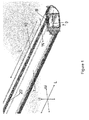
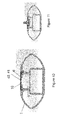
figure 1 shows a load carrying bar comprising a cover with a view in perspective; -
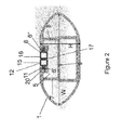
figure 2 shows the load carrying bar and the cover fromfigure 1 with a view towards the end of the load carrying bar; -
figure 3a shows the load carrying bar and the cover offigure 1 with a view towards the end of the load carrying bar and after a fastening member has been inserted in the channel of the load carrying bar; -
figure 3b shows the load carrying bar and the cover offigure 3a with a view from above; -
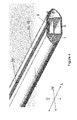
figure 4 shows a load carrying bar comprising a cover with a view in perspective; -
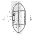
figure 5 shows the load carrying bar and the cover offigure 4 with a view towards the end of the load carrying bar; -
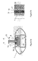
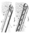
figure 6 shows a load carrying bar comprising another embodiment of a cover with a view in perspective; -
figure 7 shows a cross section of the load carrying bar offigure 6 ; -
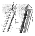
figure 8 shows a load carrying bar comprising another embodiment of a cover with a view in perspective; -
figure 9 shows a cross section of the load carrying bar offigure 8 ; -
figure 10 shows a cross section of a load carrying bar comprising another embodiment of a cover having a weak section and; -
figure 11 shows a cross section of the load carrying bar and cover offigure 10 after a fastening member has been mounted. -
Figure 1 shows aload carrying bar 1 for a roof rack. A roof rack is intended during use to be mounted to e.g. the roof of an automobile such as a car or truck. A first and a second load carrier foot are generally positioned on each side of the automobile so that theload carrying bar 1 extends transversely across the roof of the automobile. Theload carrying bar 1 is formed by extruded material such as aluminum and has a substantially oval cross section as can be seen infigures 1 and3a-3b for example with openings at each end (only one end shown infigure 1 ). The ends of theload carrying bar 1 can be sealed if desired by a separate lid, plug or by parts of the load carrier foot for example. - The
load carrying bar 1 comprises achannel 5 for receiving a fastening member for a load carrying accessory. A load carrying accessory can be a roof box, a bicycle carrier, a luggage carrier, a ski carrier, or any other load carrier suitable to mount on a roof rack. The fastening member is generally the member which is used to attached the load carrier accessory to theload carrying bar 1 and can be a screw comprising a head for example as shown infigure 3a-3b . - For the purpose of orientation, the
load carrying bar 1, and thecover 10 as described herein, has a length L usually extending along the width of the automobile, a height H usually extending along the height of the automobile, and a width W usually extending along the length of the automobile, when theload carrying bar 1 is mounted in the intended way to the automobile. - The
load carrying bar 1 comprises achannel 5 in which the fastening member is intended to be introduced when mounting the load carrier accessory for example. Thechannel 5 extends along the full length of theload carrying bar 1 and is defined by anopening 6, a first and asecond side wall floor 9. The first and thesecond side wall floor 9 of thechannel 5 forms parts of a frame work structure of theload carrying bar 1 and significantly enhances the rigidity of theload carrying bar 1. Acover 10 is arranged to substantially seal theopening 6 of thechannel 5 to reduce the air turbulence which otherwise can be formed about such channel in a load carrying bar. Thecover 10 also prevents the intrusion of dirt or rubble to the channel which could obstruct the free passage of a fastening member for a load carrier accessory and thereby make the fastening member slide less easy in thechannel 5. -
Figure 2 shows theload carrying bar 1 as seen along the length L infigure 1 .Figure 2 shows theload carrying bar 1, thechannel 5, theopening 6, the first and thesecond side walls floor 9 of thechannel 5. The width W and the height H of theload carrying bar 1 are also indicated. Thecover 10 comprises anattachment portion 11 and achannel sealing portion 12, The primary purpose of the attachment portion is to retain thecover 10 to theload carrying bar 1 and the primary purpose of the channel sealing portion is to seal theopening 6 of thechannel 5 of theload carrying bar 1. Thecover 10 shown infigure 1 is formed by a first and asecond strip member cover 10 can be formed by only one strip member if desirable. If only one strip member is used, the form or dimension of the single strip member is adapted, e.g. by having achannel sealing portion 12. - The
cover 10 in the shown embodiment comprises a first and thesecond strip member attachment portion 11 and achannel sealing portion 12. Theattachment portion 11 of thefirst strip member 15 and the second strip member respectively, is intended to retain thestrip member 15 to theload carrying bar 1, while thechannel sealing portion 12 are adapted to seal theopening 6 of thechannel 5 in a cooperative manner. Thechannel sealing portion 12 of the first and thesecond strip member opening 6 of thechannel 5 of theload carrying bar 1. Anopenable slot 17 is thus formed between the first and thesecond strip members - In the shown embodiment, the
attachment portion 11 of thefirst strip member 15 has a cross section which has a substantially spherical form adapted to be inserted into agroove 20 with a corresponding cross section. Theattachment portion 11 can be formed in other ways dependent on the desired location and extension of thecover 10 and thestrip member 15. Thegroove 20 is partly formed by a portion of theload carrying bar 1 defining theopening 6 of thechannel 5 of theload carrying bar 1, but could be attached to theload carrying bar 1 in any other fashion. The portions of theload carrying bar 1 defining theopening 6 is indicated infigure 2 as 6', 6". - The
channel sealing portion 12 of thefirst strip member 15 is formed by a portion of thefirst strip member 15 having a substantially quadric and hollow cross section. Other suitable cross sections could be oval, oblong, rectangular or the like. Thechannel sealing portion 12 could also be formed by a flap like member which cover or seal theopening 6 of thechannel 5 by overlapping theopening 6 of thechannel 5 or by overlapping a portion of a second strip member. - The
channel sealing portion 12 of thefirst strip member 15 adapted to be deformed. By permitting deformation, thecover 10 can permit access to thechannel 5 of theload carrying bar 1 for a fastening member to a load carrying bar accessory. In the shown embodiment, thechannel sealing portion 12 is hollow, i.e. has a hollow interior, which permits thefirst strip member 15 to be deformed into the void of the hollow structure. Optionally, or additionally, the deformation could be implemented by having another collapsible structure or deformable material such as an open or closed cell- foam material, e.g. formed by polyurethane, polyurethane, polypropylene, polystyrene or the like, or mixtures thereof. -
Figures 3a-3b show theload carrying bar 1 offigures 1 and2 having a fastening member 30 inserted into thechannel 5 and theslot 17 formed between the first and thesecond strip member stem 32 and ascrew head 33. Thescrew head 33 is inserted at the end of theload carrying bar 1 and slid into position along the length L of thechannel 5 of theload carrying bar 1. As is notable infigure 3b , the first and thesecond strip members opening 6 of thechannel 5 which is not occupied by the fastening member 30. Substantially only the portion in the close proximity of thestem 32 of the screw 31 is not sealed. - The arrows A and A' indicate a main direction of deformation for the
cover 10, which in the shown embodiment is along the width W of theload carrying bar 1. As thecover 10 comprises a first and asecond strip member cover 10 has in the shown embodiment two opposing deformation directions, however, both of the opposing deformation directions are along the width W of theload carrying bar 1. With specific reference tofigure 3a , thefirst strip member 15 deform substantially from the center of theopening 6 of thechannel 5 towards the left side of theopening 6 of thechannel 5, while thesecond strip member 16 deforms substantially from the center of theopening 6 of thechannel 5 towards the right side of theopening 6 of thechannel 5. In an advantageous embodiment, thecover 10 is thus adapted to be deformed in two opposing directions along the width of the load carrying bar to accommodate space for a fastening member for a load carrying bar accessory. - It should be noted that it is possible that the first and the
second strip members cover 10 having a main direction of deformation along the width of the load carrying bar is advantageous. As can be noted, not only is the main direction of deformation along the width of theload carrying bar 1, but also along the width of thechannel 5. It has been found that it is advantageous to have acover 10 arranged in the proximity of theopening 6 of thechannel 5, which is adapted to deform along the width of thechannel 5 and the width of theload carrying bar 1. - The
cover 10 can be formed by any suitable deformable but self-restoring material such as a thermoplastic material, combinations of aluminum and thermoplastic material or similar. Thechannel sealing portion 12 can be formed by a material different from theattachment portion 11 or from the same material, preferably as one unitary piece of material. -
Figure 4 shows an embodiment of acover 10 for aload carrying bar 1. As described above, theload carrying bar 1 comprises achannel 5 in which the fastening member for a load carrying bar accessory is intended to be introduced, e.g. when mounting the load carrier accessory. Thechannel 5 extends along the full length of theload carrying bar 1 and is defined by anopening 6, a first and asecond wall floor 9. The first and thesecond wall floor 9 of thechannel 5 forms parts of a frame work structure of theload carrying bar 1 adapted to enhance the rigidity of theload carrying bar 1. - As can be noticed in
figure 4 , thecover 10 comprises only one strip member 15'. Thecover 10 is in this embodiment adapted to be deformed mainly in the horizontal direction, i.e. along the width W of theload carrying bar 1 as indicated by the arrow A infigure 4 . Turning tofigure 5 , the arrow A indicate a main direction of deformation for thecover 10, which in the shown embodiment is along the width W of theload carrying bar 1. As thecover 10 in this embodiment only has one strip member 15', thecover 10 has in the shown embodiment one deformation direction. With reference tofigure 5 , the strip member 15' deforms substantially from the side of theopening 6 of thechannel 5, towards the right side of theopening 6 of thechannel 5. Before deformation, i.e. the state shown infigure 4 , the strip member 15' is in direct contact with the left side of theopening 6 of thechannel 5. In an advantageous embodiment, thecover 10 is thus adapted to be deformed in only one direction to accommodate space for a fastening member for a load carrying bar accessory. The strip member 15' is intended to return to its original form when the fastening member is removed from a specific region or from thechannel 5 of theload carrying bar 1. -
Figure 6 shows an embodiment of acover 10 for aload carrying bar 1. Theload carrying bar 1 is adapted to be connected with a first and a second load carrier foot (not shown). Thecover 10 uses the principle of sealing theopening 6 of thechannel 5 of theload carrying bar 1 by biasing a portion of thecover 10 towards the side edges of theopening 6 of thechannel 5 of theload carrying bar 1. It thus seals theopening 6 from the inside of thechannel 5 of theload carrying bar 1. Thecover 10 in the shown embodiment comprises a biasingportion 11 and achannel sealing portion 12. The biasingportion 11 of thecover 10 is adapted to bias, or retain, thechannel sealing portion 11 of thecover 10 against theopening 6 of thechannel 5 of theload carrying bar 1, or more accurately against the side edges of theopening 6 so that theopening 6 of thechannel 5 is effectively sealed. - The biasing
portion 11 of thecover 10 is formed by at least two flanges, preferably separated from each other although being connected via thechannel sealing portion 12. The shown embodiment comprises a plurality of flanges 11' preferably 10 or more, more preferably 20 or more flanges 11'. - A cross section of the
load carrying bar 1 and thecover 10 along the length L is shownfigure 7 .Figure 5 shows flanges 11' arranged substantially perpendicular to the length L of thecover 10 thus having an extension along the width W of theload carrying bar 1 after being mounted thereto. -
Figure 8 shows another embodiment of acover 10 for aload carrying bar 1. Theload carrying bar 1 is adapted to be connected with a first and a second load carrier foot (not shown). Thecover 10 used the principle of sealing theopening 6 of thechannel 5 of theload carrying bar 1 by biasing a portion of thecover 10 towards the side edges of theopening 6 of thechannel 5 of theload carrying bar 1. It thus seals theopening 6 from the inside of thechannel 5 of theload carrying bar 1. Thecover 10 in the shown embodiment comprises a biasingportion 11 and achannel sealing portion 12. The biasingportion 11 of thecover 10 is adapted to bias, or retain, thechannel sealing portion 11 of thecover 10 against theopening 6 of thechannel 5 of theload carrying bar 1, or more accurately against the side edges of theopening 6 so that theopening 6 of thechannel 5 is effectively sealed. - The biasing
portion 11 of thecover 10 is formed by at least twoflanges 11", preferably separated from each other although being connected via thechannel sealing portion 12. The shown embodiment comprises a first and a second offlange 11". It is however possible that the biasingportion 11 comprises more flanges although in such case those flanges are preferably aligned along the length L ofcover 10. The first and thesecond flanges 11" can be formed by a number of individual flanges, as indicated by the dashed lines infigure 7 , which together substantially have the same form as the first and thesecond flanges 11" shown infigures 6 and 7 . The number of flanges can be 2 or more, 5 or more, optionally 10 or more flanges. - A cross section of the
load carrying bar 1 and thecover 10 along the length L is shownfigure 9 .Figure 5 showsflanges 11" arranged with an extension substantially parallel to the length L of thecover 10 thus having an extension along the length L of theload carrying bar 1 after being mounted thereto. - The reference 20' in
figures 1-9 is used to illustrate how a portion of thecover 10 has been deformed after a fastening member has been inserted in thechannel 5 of theload carrying bar 1. The fastening member (not shown) can be similar or identical to thefastening member 20 described with reference tofigures 3a-3b . -
Figure 10 shows an embodiment in which thecover 10 comprises a weak section 40. The weak section 40 is in the shown embodiment formed by a cut out 41 in thecover 10. The cut out extends along the length L of thecover 10 and theload carrying bar 1 and is preferably arranged at the centre of thecover 10, as shown infigure 10 . The cut out preferably extends along the full length L of thecover 10 The weak section permits a user to run a fastening member, such as a screw and the one shown infigure 3a andfigure 11 , along the length of thechannel 5 so that a portion of the fastening member protrudes through theopening 6 of thechannel 5. The fastening member will during such motion split thecover 10 at the weak section and deform thecover 10 in a horizontal and vertical direction, as is illustrated infigure 11 . This is advantageous as a large portion of thechannel 5 can remain fully covered by thecover 10 even after a load carrying bar accessory has been mounted. - Generally, cover 10 can be formed by any suitable deformable but self-restoring material such as a thermoplastic material, combinations of aluminum and thermoplastic material or similar. The channel sealing portion can be formed by a material different from the biasing
portion 11 of thecover 10, or from the same material preferably as one unitary piece of material. In an embodiment, the channel sealing portion comprises a first thermoplastic material and the biasing portion comprises a second thermoplastic material different from the first thermoplastic material.
Claims (18)
- A load carrying bar (1) for a roof rack, said load carrying bar (1) having a length (L), a height (H) and a width (W), said load carrying bar (1) comprising a channel (5) with an opening (6) for receiving a fastening member of a load carrying bar accessory, a cover (10) being arranged to seal at least a portion of said opening (6) of said channel (5) of said load carrying bar (1), said cover (10) comprising an attachment portion (11) for attaching said cover (10) to said load carrying bar (1) and channel sealing portion (12) adapted to substantially seal at least a portion of said opening (6) of said channel (5) of said load carrying bar (1),
characterized in that
said cover (10) is configured to have a direction of deformation along the width (W) of said load carrying bar (1) to provide space for said fastening member of said load carrying bar accessory. - The load carrying bar (1) according to claim 1, wherein said cover (10) has a main direction of deformation along the width (W) of said load carrying bar (1) to provide space for said fastening member of said load carrying bar accessory.
- The load carrying bar (1) according to claim 1 or 2, wherein said cover (10) comprises a first and a second strip member (15, 16), said first and said second strip members (15, 16) extending parallel with said channel (5) of said load carrying bar (1) and being adapted to cooperate to seal said opening (6) of said channel (5) of said load carrying bar (1).
- The load carrying bar (1) according to claim 3, wherein said first and said second strip members (15,16) of said cover (10) are adapted to be deformed in opposite directions (A, A') to provide space for said fastening member of said load carrying bar accessory.
- The load carrying bar (1) according to any one of the preceding claims, wherein said channel (5) of said load carrying bar (1) comprises side walls (7, 8) and a floor (9), and in that said attachment portion (11) of said cover (10) is attached in the proximity of said opening (6) of said channel (5), to retain said cover (10) to said load carrying bar (1).
- The load carrying bar (1) according to claim 5, wherein said attachment portion (11) of said cover (10) is attached in said opening (6) of said channel (5), to retain said cover (10) to said load carrying bar (1).
- The load carrying bar (1) according to claim 6, said load carrying bar (1) comprises at least one groove (20), said at least one groove (20) arranged in said opening (6) of said channel (5), and wherein said attachment portion (11) of said cover (10) is arranged in said groove (20) to retain said cover (10) to said load carrying bar (1).
- The load carrying bar (1) according to claim 1, wherein said cover (10) is formed by only one strip member (15'), said only one strip member (15') extending parallel with said channel (5) of said load carrying bar (1) and being adapted to seal said opening (6) of said channel (5) of said load carrying bar (1).
- The load carrying bar (1) according to any one of the preceding claims, wherein said cover (10) is formed by at least one strip member (15, 15'), wherein said at least one strip member (15, 15') has a hollow interior.
- The load carrying bar (1) according to claim 9, wherein a portion of said at least one strip member (15, 15') is configured to collapse into said hollow interior to enable said deformation along the width (W) of said load carrying bar (1) to provide space for said fastening member of said load carrying bar accessory.
- The load carrying bar (1) according to claim 1, wherein said cover (10) comprises a weak section (40), said weak section being adapted to rupture during mounting of a fastening member for a load carrying bar accessory.
- The load carrying bar (1) according to claim 11, wherein said weak section is formed by a cut out (41), said cut out extending along the length of said cover (10).
- A load carrying bar (1) for a roof rack, said load carrying bar (1) having a length (L), a height (H) and a width (W), said load carrying bar (1) comprising a channel (5) with an opening (6) for receiving a fastening member of a load carrying bar accessory, a cover (10) being arranged to seal at least a portion of said opening (6) of said channel (5) of said load carrying bar (1), said cover (10) comprising a channel sealing portion (12) adapted to substantially seal said opening (6) of said channel (5) of said load carrying bar (1) and a biasing portion (11) adapted to bias or retain said channel sealing portion (12) towards said opening (6) of said channel (5) of said load carrying bar (1),
characterized in that
said biasing portion (11) of said cover (10) is formed by at least two separate flanges (13, 14) extending from said channel sealing portion (12) of said cover (10). - The load carrying bar (1) according to claim 13, wherein said at least two separate flanges (11", 11") extends and are attached to said channel sealing portion (12) substantially along the full length (L) of the cover (10).
- The load carrying bar (1) according to any one of the claims 13-14, wherein said at least two separate flanges (11", 11") extends outwards from the channel sealing portion (12) and towards the side walls (7, 8) of the channel (5).
- The load carrying bar (1) according to claim 13, wherein said at least two separate flanges (11', 11') extends and are attached to said channel sealing portion (12) substantially along the full width (W) of the cover (10).
- The load carrying bar (1) according to any one of the claims 13-16, wherein said biasing portion (11) comprises at least 10 separate flanges (11').
- The load carrying bar (1) according to any one of the claims 13-17, wherein said flanges (11') are arranged with an angle (α) to said channel sealing portion (12), said angle (α) preferably being of from 15-80 degrees.
Priority Applications (12)
| Application Number | Priority Date | Filing Date | Title |
|---|---|---|---|
| EP13167521.7A EP2803535B1 (en) | 2013-05-13 | 2013-05-13 | A load carrying bar |
| EP16165055.1A EP3059124B1 (en) | 2013-05-13 | 2013-05-13 | A load carrying bar |
| PL16165055T PL3059124T3 (en) | 2013-05-13 | 2013-05-13 | A load carrying bar |
| EP17158063.2A EP3192702B1 (en) | 2013-05-13 | 2013-05-13 | A load carrying bar |
| PCT/EP2014/059721 WO2014184172A2 (en) | 2013-05-13 | 2014-05-13 | A load carrying bar |
| AU2014267373A AU2014267373B2 (en) | 2013-05-13 | 2014-05-13 | A load carrying bar |
| BR112015028390-0A BR112015028390B1 (en) | 2013-05-13 | 2014-05-13 | LOAD TRANSPORT BAR FOR A ROOF LUGGAGE |
| BR122018005485-9A BR122018005485B1 (en) | 2013-05-13 | 2014-05-13 | Cargo bar for roof rack |
| US14/890,575 US10442363B2 (en) | 2013-05-13 | 2014-05-13 | Load carrying bar |
| CN201480027593.9A CN105228860B (en) | 2013-05-13 | 2014-05-13 | A load carrying bar |
| CN201710432392.2A CN107415843B (en) | 2013-05-13 | 2014-05-13 | Bearing strip |
| AU2018203370A AU2018203370B2 (en) | 2013-05-13 | 2018-05-15 | A Load Carrying Bar |
Applications Claiming Priority (1)
| Application Number | Priority Date | Filing Date | Title |
|---|---|---|---|
| EP13167521.7A EP2803535B1 (en) | 2013-05-13 | 2013-05-13 | A load carrying bar |
Related Child Applications (2)
| Application Number | Title | Priority Date | Filing Date |
|---|---|---|---|
| EP17158063.2A Division EP3192702B1 (en) | 2013-05-13 | 2013-05-13 | A load carrying bar |
| EP16165055.1A Division EP3059124B1 (en) | 2013-05-13 | 2013-05-13 | A load carrying bar |
Publications (2)
| Publication Number | Publication Date |
|---|---|
| EP2803535A1 true EP2803535A1 (en) | 2014-11-19 |
| EP2803535B1 EP2803535B1 (en) | 2016-04-27 |
Family
ID=48444122
Family Applications (3)
| Application Number | Title | Priority Date | Filing Date |
|---|---|---|---|
| EP17158063.2A Active EP3192702B1 (en) | 2013-05-13 | 2013-05-13 | A load carrying bar |
| EP13167521.7A Active EP2803535B1 (en) | 2013-05-13 | 2013-05-13 | A load carrying bar |
| EP16165055.1A Active EP3059124B1 (en) | 2013-05-13 | 2013-05-13 | A load carrying bar |
Family Applications Before (1)
| Application Number | Title | Priority Date | Filing Date |
|---|---|---|---|
| EP17158063.2A Active EP3192702B1 (en) | 2013-05-13 | 2013-05-13 | A load carrying bar |
Family Applications After (1)
| Application Number | Title | Priority Date | Filing Date |
|---|---|---|---|
| EP16165055.1A Active EP3059124B1 (en) | 2013-05-13 | 2013-05-13 | A load carrying bar |
Country Status (7)
| Country | Link |
|---|---|
| US (1) | US10442363B2 (en) |
| EP (3) | EP3192702B1 (en) |
| CN (2) | CN107415843B (en) |
| AU (2) | AU2014267373B2 (en) |
| BR (2) | BR122018005485B1 (en) |
| PL (1) | PL3059124T3 (en) |
| WO (1) | WO2014184172A2 (en) |
Cited By (4)
| Publication number | Priority date | Publication date | Assignee | Title |
|---|---|---|---|---|
| CN110049900A (en) * | 2016-12-20 | 2019-07-23 | 拓乐瑞典股份公司 | Vehicle load carrier |
| EP3590766A1 (en) | 2018-07-02 | 2020-01-08 | Thule Sweden AB | Load carrier |
| USD947097S1 (en) * | 2019-10-02 | 2022-03-29 | Rhino Rack Australia Pty Limited | Underbar for roof rack with aperture/window |
| RU2778819C2 (en) * | 2018-07-02 | 2022-08-25 | Туле Сведен Аб (Thule Sweden Ab) | Load holder |
Families Citing this family (6)
| Publication number | Priority date | Publication date | Assignee | Title |
|---|---|---|---|---|
| US10220792B2 (en) * | 2016-08-24 | 2019-03-05 | Honda Patents & Technologies North America, Llc | Roof rack crossbar |
| TWM541967U (en) * | 2017-02-17 | 2017-05-21 | King Roof Industrial Co Ltd | Car roof cross bar |
| EP3470271B1 (en) | 2017-10-16 | 2019-10-02 | Thule Sweden AB | Load carrier |
| US10829007B2 (en) * | 2018-01-26 | 2020-11-10 | Adient Engineering and IP GmbH | Active long track cover |
| US11453343B1 (en) | 2021-03-04 | 2022-09-27 | Adrian Steel Company | Roof rail assembly for a vehicle |
| DE102022124206A1 (en) | 2022-09-21 | 2024-03-21 | Audi Aktiengesellschaft | Closing device for a floor gap of a vehicle and vehicle |
Citations (4)
| Publication number | Priority date | Publication date | Assignee | Title |
|---|---|---|---|---|
| DE4113230A1 (en) * | 1990-11-09 | 1992-10-29 | Bayerische Motoren Werke Ag | ROOF RACK FOR VEHICLES |
| US6176404B1 (en) | 1998-06-19 | 2001-01-23 | Automaxi Industries | Seal adapted to cover the longitudinal groove in a roof bar |
| WO2009038479A1 (en) | 2007-09-21 | 2009-03-26 | Hubco Automotive Ltd | Resilient infill |
| WO2009038481A1 (en) * | 2007-09-21 | 2009-03-26 | Hubco Automotive Ltd | Roof rack and versatile leg for a roof rack |
Family Cites Families (14)
| Publication number | Priority date | Publication date | Assignee | Title |
|---|---|---|---|---|
| US3213584A (en) * | 1963-07-31 | 1965-10-26 | Standard Products Co | Gaskets |
| US3606432A (en) * | 1968-12-02 | 1971-09-20 | Robert W Honatzis | Protector strip |
| US4015760A (en) * | 1975-08-14 | 1977-04-05 | Bott John Anthony | Vehicle article carrier |
| US4432478A (en) * | 1981-05-04 | 1984-02-21 | Bott John Anthony | Vehicle article carrier |
| DE3209912A1 (en) * | 1981-12-24 | 1983-10-06 | Opel Adam Ag | Vehicle roof, in particular motor vehicle roof |
| US5207365A (en) * | 1988-09-20 | 1993-05-04 | Bott John Anthony | Article carrier |
| US4911349A (en) * | 1989-07-03 | 1990-03-27 | Starboard Industries, Inc. | End cap with captive stud for article carriers |
| DE4108059A1 (en) * | 1991-03-13 | 1992-09-17 | Votex Gmbh | CROSS-SECTIONAL FORM OF A CROSSBAR ON A ROOF RACK OF A VEHICLE |
| SE470433B (en) * | 1992-08-06 | 1994-03-07 | Holmbergs Fab Ab Brdr | Device for adjustable fastening of a belt |
| US5282560A (en) * | 1993-04-26 | 1994-02-01 | Ford Motor Company | Luggage rack with wind noise reducer |
| US5474218A (en) * | 1994-07-25 | 1995-12-12 | Chrysler Corporation | Article carrier |
| AU3631499A (en) * | 1998-04-22 | 1999-11-08 | Hubco Industries Limited | Roof rack or load carrier |
| CN102310814B (en) * | 2011-09-09 | 2013-08-07 | 周用强 | Roof luggage rack for automobile |
| WO2014022435A1 (en) * | 2012-07-30 | 2014-02-06 | Yakima Innovation Development Corporation | Crossbar t-slot infill |
-
2013
- 2013-05-13 EP EP17158063.2A patent/EP3192702B1/en active Active
- 2013-05-13 EP EP13167521.7A patent/EP2803535B1/en active Active
- 2013-05-13 EP EP16165055.1A patent/EP3059124B1/en active Active
- 2013-05-13 PL PL16165055T patent/PL3059124T3/en unknown
-
2014
- 2014-05-13 AU AU2014267373A patent/AU2014267373B2/en active Active
- 2014-05-13 CN CN201710432392.2A patent/CN107415843B/en active Active
- 2014-05-13 BR BR122018005485-9A patent/BR122018005485B1/en active IP Right Grant
- 2014-05-13 BR BR112015028390-0A patent/BR112015028390B1/en active IP Right Grant
- 2014-05-13 US US14/890,575 patent/US10442363B2/en active Active
- 2014-05-13 CN CN201480027593.9A patent/CN105228860B/en active Active
- 2014-05-13 WO PCT/EP2014/059721 patent/WO2014184172A2/en active Application Filing
-
2018
- 2018-05-15 AU AU2018203370A patent/AU2018203370B2/en active Active
Patent Citations (4)
| Publication number | Priority date | Publication date | Assignee | Title |
|---|---|---|---|---|
| DE4113230A1 (en) * | 1990-11-09 | 1992-10-29 | Bayerische Motoren Werke Ag | ROOF RACK FOR VEHICLES |
| US6176404B1 (en) | 1998-06-19 | 2001-01-23 | Automaxi Industries | Seal adapted to cover the longitudinal groove in a roof bar |
| WO2009038479A1 (en) | 2007-09-21 | 2009-03-26 | Hubco Automotive Ltd | Resilient infill |
| WO2009038481A1 (en) * | 2007-09-21 | 2009-03-26 | Hubco Automotive Ltd | Roof rack and versatile leg for a roof rack |
Cited By (9)
| Publication number | Priority date | Publication date | Assignee | Title |
|---|---|---|---|---|
| CN110049900A (en) * | 2016-12-20 | 2019-07-23 | 拓乐瑞典股份公司 | Vehicle load carrier |
| EP3590766A1 (en) | 2018-07-02 | 2020-01-08 | Thule Sweden AB | Load carrier |
| WO2020007656A1 (en) | 2018-07-02 | 2020-01-09 | Thule Sweden Ab | Load carrier |
| EP3733456A1 (en) | 2018-07-02 | 2020-11-04 | Thule Sweden AB | Load carrier |
| EP3831657A1 (en) | 2018-07-02 | 2021-06-09 | Thule Sweden AB | Load carrier |
| RU2778819C2 (en) * | 2018-07-02 | 2022-08-25 | Туле Сведен Аб (Thule Sweden Ab) | Load holder |
| EP4140818A1 (en) | 2018-07-02 | 2023-03-01 | Thule Sweden AB | Load carrier |
| EP4342736A2 (en) | 2018-07-02 | 2024-03-27 | Thule Sweden AB | Load carrier |
| USD947097S1 (en) * | 2019-10-02 | 2022-03-29 | Rhino Rack Australia Pty Limited | Underbar for roof rack with aperture/window |
Also Published As
| Publication number | Publication date |
|---|---|
| EP3059124B1 (en) | 2017-08-16 |
| PL3059124T3 (en) | 2017-12-29 |
| CN105228860B (en) | 2017-05-10 |
| EP3059124A3 (en) | 2016-11-09 |
| BR122018005485B1 (en) | 2022-01-25 |
| US20160082892A1 (en) | 2016-03-24 |
| EP3192702B1 (en) | 2018-08-22 |
| EP3192702A1 (en) | 2017-07-19 |
| CN107415843A (en) | 2017-12-01 |
| CN105228860A (en) | 2016-01-06 |
| EP2803535B1 (en) | 2016-04-27 |
| WO2014184172A3 (en) | 2015-01-22 |
| AU2014267373B2 (en) | 2018-03-01 |
| BR112015028390A2 (en) | 2017-07-25 |
| BR112015028390B1 (en) | 2021-12-21 |
| EP3059124A2 (en) | 2016-08-24 |
| AU2014267373A1 (en) | 2015-12-24 |
| AU2018203370B2 (en) | 2018-10-25 |
| US10442363B2 (en) | 2019-10-15 |
| CN107415843B (en) | 2020-12-08 |
| AU2018203370A1 (en) | 2018-05-31 |
| WO2014184172A2 (en) | 2014-11-20 |
Similar Documents
| Publication | Publication Date | Title |
|---|---|---|
| EP3059124B1 (en) | A load carrying bar | |
| CN111417541B (en) | Adjustable vehicle side pedal assembly | |
| US20150063938A1 (en) | Partition Assembly for a Vehicular Cargo Area | |
| US9914206B1 (en) | Tool bag | |
| KR20110019680A (en) | Cap employed for closing opening and side bar assembly of roof carrier for vehicle comprising the same | |
| CA2825604C (en) | Roof rack with an indication device for a load carrier foot | |
| US6340195B1 (en) | Truckbox cover and sidewall extension attachment | |
| KR102102282B1 (en) | Vehicle cargo carrier | |
| BR102015028844B1 (en) | VEHICLE SIDE STEPS | |
| US6329595B1 (en) | Concealable electrical outlet box system | |
| JP3692280B2 (en) | Cover member mounting structure for vehicle roof groove | |
| IT9035803U1 (en) | CARRIER SUPPORT FOR VEHICLE LUGGAGE RACKS | |
| JP6681200B2 (en) | Vehicle storage structure | |
| JPH1134749A (en) | Roof rail mounting structure for vehicle | |
| DE2810912A1 (en) | Roof rack mounted storage box - has holes to hold extended loads with end seals and locating grooves | |
| DE102023104479A1 (en) | LUGGAGE CONTAINER FOR MOUNTING ON A BICYCLE | |
| BR202017002987Y1 (en) | BAG SEALING BOARD FOR MOTORCYCLES | |
| JPH0356125Y2 (en) | ||
| EP1378424A2 (en) | Detachable stake for supporting the canopy of trucks, trailers and the like | |
| US20170361876A1 (en) | Vehicle styling bar | |
| IT202100002180A1 (en) | VEHICLE SEAT BOX AND SEAT ASSEMBLY INCLUDING SUCH BOX | |
| DE19527963A1 (en) | Box or storage element for use in vehicles to accommodate at least one umbrella | |
| KR19980053415U (en) | Trunk cover of a wagon vehicle |
Legal Events
| Date | Code | Title | Description |
|---|---|---|---|
| PUAI | Public reference made under article 153(3) epc to a published international application that has entered the european phase |
Free format text: ORIGINAL CODE: 0009012 |
|
| 17P | Request for examination filed |
Effective date: 20130513 |
|
| AK | Designated contracting states |
Kind code of ref document: A1 Designated state(s): AL AT BE BG CH CY CZ DE DK EE ES FI FR GB GR HR HU IE IS IT LI LT LU LV MC MK MT NL NO PL PT RO RS SE SI SK SM TR |
|
| AX | Request for extension of the european patent |
Extension state: BA ME |
|
| R17P | Request for examination filed (corrected) |
Effective date: 20150519 |
|
| RBV | Designated contracting states (corrected) |
Designated state(s): AL AT BE BG CH CY CZ DE DK EE ES FI FR GB GR HR HU IE IS IT LI LT LU LV MC MK MT NL NO PL PT RO RS SE SI SK SM TR |
|
| GRAP | Despatch of communication of intention to grant a patent |
Free format text: ORIGINAL CODE: EPIDOSNIGR1 |
|
| INTG | Intention to grant announced |
Effective date: 20151118 |
|
| GRAS | Grant fee paid |
Free format text: ORIGINAL CODE: EPIDOSNIGR3 |
|
| GRAA | (expected) grant |
Free format text: ORIGINAL CODE: 0009210 |
|
| AK | Designated contracting states |
Kind code of ref document: B1 Designated state(s): AL AT BE BG CH CY CZ DE DK EE ES FI FR GB GR HR HU IE IS IT LI LT LU LV MC MK MT NL NO PL PT RO RS SE SI SK SM TR |
|
| REG | Reference to a national code |
Ref country code: GB Ref legal event code: FG4D |
|
| REG | Reference to a national code |
Ref country code: CH Ref legal event code: EP |
|
| REG | Reference to a national code |
Ref country code: AT Ref legal event code: REF Ref document number: 794369 Country of ref document: AT Kind code of ref document: T Effective date: 20160515 |
|
| REG | Reference to a national code |
Ref country code: IE Ref legal event code: FG4D |
|
| REG | Reference to a national code |
Ref country code: DE Ref legal event code: R096 Ref document number: 602013006869 Country of ref document: DE |
|
| REG | Reference to a national code |
Ref country code: SE Ref legal event code: TRGR |
|
| REG | Reference to a national code |
Ref country code: FR Ref legal event code: PLFP Year of fee payment: 4 |
|
| REG | Reference to a national code |
Ref country code: LT Ref legal event code: MG4D |
|
| PG25 | Lapsed in a contracting state [announced via postgrant information from national office to epo] |
Ref country code: BE Free format text: LAPSE BECAUSE OF NON-PAYMENT OF DUE FEES Effective date: 20160531 |
|
| REG | Reference to a national code |
Ref country code: NL Ref legal event code: MP Effective date: 20160427 |
|
| REG | Reference to a national code |
Ref country code: AT Ref legal event code: MK05 Ref document number: 794369 Country of ref document: AT Kind code of ref document: T Effective date: 20160427 |
|
| PG25 | Lapsed in a contracting state [announced via postgrant information from national office to epo] |
Ref country code: NL Free format text: LAPSE BECAUSE OF FAILURE TO SUBMIT A TRANSLATION OF THE DESCRIPTION OR TO PAY THE FEE WITHIN THE PRESCRIBED TIME-LIMIT Effective date: 20160427 |
|
| PG25 | Lapsed in a contracting state [announced via postgrant information from national office to epo] |
Ref country code: PL Free format text: LAPSE BECAUSE OF FAILURE TO SUBMIT A TRANSLATION OF THE DESCRIPTION OR TO PAY THE FEE WITHIN THE PRESCRIBED TIME-LIMIT Effective date: 20160427 Ref country code: LT Free format text: LAPSE BECAUSE OF FAILURE TO SUBMIT A TRANSLATION OF THE DESCRIPTION OR TO PAY THE FEE WITHIN THE PRESCRIBED TIME-LIMIT Effective date: 20160427 Ref country code: NO Free format text: LAPSE BECAUSE OF FAILURE TO SUBMIT A TRANSLATION OF THE DESCRIPTION OR TO PAY THE FEE WITHIN THE PRESCRIBED TIME-LIMIT Effective date: 20160727 Ref country code: FI Free format text: LAPSE BECAUSE OF FAILURE TO SUBMIT A TRANSLATION OF THE DESCRIPTION OR TO PAY THE FEE WITHIN THE PRESCRIBED TIME-LIMIT Effective date: 20160427 |
|
| PG25 | Lapsed in a contracting state [announced via postgrant information from national office to epo] |
Ref country code: PT Free format text: LAPSE BECAUSE OF FAILURE TO SUBMIT A TRANSLATION OF THE DESCRIPTION OR TO PAY THE FEE WITHIN THE PRESCRIBED TIME-LIMIT Effective date: 20160829 Ref country code: AT Free format text: LAPSE BECAUSE OF FAILURE TO SUBMIT A TRANSLATION OF THE DESCRIPTION OR TO PAY THE FEE WITHIN THE PRESCRIBED TIME-LIMIT Effective date: 20160427 Ref country code: RS Free format text: LAPSE BECAUSE OF FAILURE TO SUBMIT A TRANSLATION OF THE DESCRIPTION OR TO PAY THE FEE WITHIN THE PRESCRIBED TIME-LIMIT Effective date: 20160427 Ref country code: ES Free format text: LAPSE BECAUSE OF FAILURE TO SUBMIT A TRANSLATION OF THE DESCRIPTION OR TO PAY THE FEE WITHIN THE PRESCRIBED TIME-LIMIT Effective date: 20160427 Ref country code: HR Free format text: LAPSE BECAUSE OF FAILURE TO SUBMIT A TRANSLATION OF THE DESCRIPTION OR TO PAY THE FEE WITHIN THE PRESCRIBED TIME-LIMIT Effective date: 20160427 Ref country code: GR Free format text: LAPSE BECAUSE OF FAILURE TO SUBMIT A TRANSLATION OF THE DESCRIPTION OR TO PAY THE FEE WITHIN THE PRESCRIBED TIME-LIMIT Effective date: 20160728 Ref country code: LV Free format text: LAPSE BECAUSE OF FAILURE TO SUBMIT A TRANSLATION OF THE DESCRIPTION OR TO PAY THE FEE WITHIN THE PRESCRIBED TIME-LIMIT Effective date: 20160427 |
|
| PG25 | Lapsed in a contracting state [announced via postgrant information from national office to epo] |
Ref country code: BE Free format text: LAPSE BECAUSE OF FAILURE TO SUBMIT A TRANSLATION OF THE DESCRIPTION OR TO PAY THE FEE WITHIN THE PRESCRIBED TIME-LIMIT Effective date: 20160427 Ref country code: IT Free format text: LAPSE BECAUSE OF FAILURE TO SUBMIT A TRANSLATION OF THE DESCRIPTION OR TO PAY THE FEE WITHIN THE PRESCRIBED TIME-LIMIT Effective date: 20160427 |
|
| REG | Reference to a national code |
Ref country code: CH Ref legal event code: PL |
|
| REG | Reference to a national code |
Ref country code: DE Ref legal event code: R097 Ref document number: 602013006869 Country of ref document: DE |
|
| PG25 | Lapsed in a contracting state [announced via postgrant information from national office to epo] |
Ref country code: LI Free format text: LAPSE BECAUSE OF NON-PAYMENT OF DUE FEES Effective date: 20160531 Ref country code: RO Free format text: LAPSE BECAUSE OF FAILURE TO SUBMIT A TRANSLATION OF THE DESCRIPTION OR TO PAY THE FEE WITHIN THE PRESCRIBED TIME-LIMIT Effective date: 20160427 Ref country code: SK Free format text: LAPSE BECAUSE OF FAILURE TO SUBMIT A TRANSLATION OF THE DESCRIPTION OR TO PAY THE FEE WITHIN THE PRESCRIBED TIME-LIMIT Effective date: 20160427 Ref country code: CZ Free format text: LAPSE BECAUSE OF FAILURE TO SUBMIT A TRANSLATION OF THE DESCRIPTION OR TO PAY THE FEE WITHIN THE PRESCRIBED TIME-LIMIT Effective date: 20160427 Ref country code: MC Free format text: LAPSE BECAUSE OF FAILURE TO SUBMIT A TRANSLATION OF THE DESCRIPTION OR TO PAY THE FEE WITHIN THE PRESCRIBED TIME-LIMIT Effective date: 20160427 Ref country code: CH Free format text: LAPSE BECAUSE OF NON-PAYMENT OF DUE FEES Effective date: 20160531 Ref country code: EE Free format text: LAPSE BECAUSE OF FAILURE TO SUBMIT A TRANSLATION OF THE DESCRIPTION OR TO PAY THE FEE WITHIN THE PRESCRIBED TIME-LIMIT Effective date: 20160427 Ref country code: DK Free format text: LAPSE BECAUSE OF FAILURE TO SUBMIT A TRANSLATION OF THE DESCRIPTION OR TO PAY THE FEE WITHIN THE PRESCRIBED TIME-LIMIT Effective date: 20160427 |
|
| REG | Reference to a national code |
Ref country code: IE Ref legal event code: MM4A |
|
| PG25 | Lapsed in a contracting state [announced via postgrant information from national office to epo] |
Ref country code: SM Free format text: LAPSE BECAUSE OF FAILURE TO SUBMIT A TRANSLATION OF THE DESCRIPTION OR TO PAY THE FEE WITHIN THE PRESCRIBED TIME-LIMIT Effective date: 20160427 |
|
| PLBE | No opposition filed within time limit |
Free format text: ORIGINAL CODE: 0009261 |
|
| STAA | Information on the status of an ep patent application or granted ep patent |
Free format text: STATUS: NO OPPOSITION FILED WITHIN TIME LIMIT |
|
| 26N | No opposition filed |
Effective date: 20170130 |
|
| REG | Reference to a national code |
Ref country code: FR Ref legal event code: PLFP Year of fee payment: 5 |
|
| PG25 | Lapsed in a contracting state [announced via postgrant information from national office to epo] |
Ref country code: IE Free format text: LAPSE BECAUSE OF NON-PAYMENT OF DUE FEES Effective date: 20160513 Ref country code: SI Free format text: LAPSE BECAUSE OF FAILURE TO SUBMIT A TRANSLATION OF THE DESCRIPTION OR TO PAY THE FEE WITHIN THE PRESCRIBED TIME-LIMIT Effective date: 20160427 |
|
| REG | Reference to a national code |
Ref country code: FR Ref legal event code: PLFP Year of fee payment: 6 |
|
| PG25 | Lapsed in a contracting state [announced via postgrant information from national office to epo] |
Ref country code: HU Free format text: LAPSE BECAUSE OF FAILURE TO SUBMIT A TRANSLATION OF THE DESCRIPTION OR TO PAY THE FEE WITHIN THE PRESCRIBED TIME-LIMIT; INVALID AB INITIO Effective date: 20130513 |
|
| PG25 | Lapsed in a contracting state [announced via postgrant information from national office to epo] |
Ref country code: LU Free format text: LAPSE BECAUSE OF NON-PAYMENT OF DUE FEES Effective date: 20160513 Ref country code: MK Free format text: LAPSE BECAUSE OF FAILURE TO SUBMIT A TRANSLATION OF THE DESCRIPTION OR TO PAY THE FEE WITHIN THE PRESCRIBED TIME-LIMIT Effective date: 20160427 Ref country code: IS Free format text: LAPSE BECAUSE OF FAILURE TO SUBMIT A TRANSLATION OF THE DESCRIPTION OR TO PAY THE FEE WITHIN THE PRESCRIBED TIME-LIMIT Effective date: 20160427 Ref country code: MT Free format text: LAPSE BECAUSE OF NON-PAYMENT OF DUE FEES Effective date: 20160531 Ref country code: CY Free format text: LAPSE BECAUSE OF FAILURE TO SUBMIT A TRANSLATION OF THE DESCRIPTION OR TO PAY THE FEE WITHIN THE PRESCRIBED TIME-LIMIT Effective date: 20160427 |
|
| PG25 | Lapsed in a contracting state [announced via postgrant information from national office to epo] |
Ref country code: BG Free format text: LAPSE BECAUSE OF FAILURE TO SUBMIT A TRANSLATION OF THE DESCRIPTION OR TO PAY THE FEE WITHIN THE PRESCRIBED TIME-LIMIT Effective date: 20160427 |
|
| PG25 | Lapsed in a contracting state [announced via postgrant information from national office to epo] |
Ref country code: TR Free format text: LAPSE BECAUSE OF FAILURE TO SUBMIT A TRANSLATION OF THE DESCRIPTION OR TO PAY THE FEE WITHIN THE PRESCRIBED TIME-LIMIT Effective date: 20160427 Ref country code: AL Free format text: LAPSE BECAUSE OF FAILURE TO SUBMIT A TRANSLATION OF THE DESCRIPTION OR TO PAY THE FEE WITHIN THE PRESCRIBED TIME-LIMIT Effective date: 20160427 |
|
| P01 | Opt-out of the competence of the unified patent court (upc) registered |
Effective date: 20230528 |
|
| PGFP | Annual fee paid to national office [announced via postgrant information from national office to epo] |
Ref country code: FR Payment date: 20230523 Year of fee payment: 11 Ref country code: DE Payment date: 20230530 Year of fee payment: 11 |
|
| PGFP | Annual fee paid to national office [announced via postgrant information from national office to epo] |
Ref country code: SE Payment date: 20230524 Year of fee payment: 11 |
|
| PGFP | Annual fee paid to national office [announced via postgrant information from national office to epo] |
Ref country code: GB Payment date: 20230523 Year of fee payment: 11 |